EP2305089A1 - Electric cleaner - Google Patents
Electric cleaner Download PDFInfo
- Publication number
- EP2305089A1 EP2305089A1 EP09773252A EP09773252A EP2305089A1 EP 2305089 A1 EP2305089 A1 EP 2305089A1 EP 09773252 A EP09773252 A EP 09773252A EP 09773252 A EP09773252 A EP 09773252A EP 2305089 A1 EP2305089 A1 EP 2305089A1
- Authority
- EP
- European Patent Office
- Prior art keywords
- main body
- rear wheel
- cleaned
- case
- dust
- Prior art date
- Legal status (The legal status is an assumption and is not a legal conclusion. Google has not performed a legal analysis and makes no representation as to the accuracy of the status listed.)
- Withdrawn
Links
- 230000005484 gravity Effects 0.000 claims abstract description 4
- 239000004744 fabric Substances 0.000 claims description 17
- 239000011347 resin Substances 0.000 claims 1
- 229920005989 resin Polymers 0.000 claims 1
- 230000002542 deteriorative effect Effects 0.000 abstract description 4
- 239000000428 dust Substances 0.000 description 94
- 238000009423 ventilation Methods 0.000 description 10
- 238000005192 partition Methods 0.000 description 7
- 229920003002 synthetic resin Polymers 0.000 description 5
- 239000000057 synthetic resin Substances 0.000 description 5
- 238000000926 separation method Methods 0.000 description 4
- 238000004140 cleaning Methods 0.000 description 3
- 238000012856 packing Methods 0.000 description 3
- 230000002093 peripheral effect Effects 0.000 description 3
- 229920001971 elastomer Polymers 0.000 description 2
- 238000001914 filtration Methods 0.000 description 2
- 238000011144 upstream manufacturing Methods 0.000 description 2
- 210000000078 claw Anatomy 0.000 description 1
- 230000008602 contraction Effects 0.000 description 1
- 230000000694 effects Effects 0.000 description 1
- 239000000806 elastomer Substances 0.000 description 1
- 230000007774 longterm Effects 0.000 description 1
- 239000002184 metal Substances 0.000 description 1
- 238000007789 sealing Methods 0.000 description 1
Images



Classifications
-
- A—HUMAN NECESSITIES
- A47—FURNITURE; DOMESTIC ARTICLES OR APPLIANCES; COFFEE MILLS; SPICE MILLS; SUCTION CLEANERS IN GENERAL
- A47L—DOMESTIC WASHING OR CLEANING; SUCTION CLEANERS IN GENERAL
- A47L9/00—Details or accessories of suction cleaners, e.g. mechanical means for controlling the suction or for effecting pulsating action; Storing devices specially adapted to suction cleaners or parts thereof; Carrying-vehicles specially adapted for suction cleaners
- A47L9/009—Carrying-vehicles; Arrangements of trollies or wheels; Means for avoiding mechanical obstacles
Definitions
- the present invention relates to an electric vacuum cleaner including traveling wheels provided rotatably on both sides of a main body case.
- this type of electric vacuum cleaner includes a cleaner main body as a main body part including a main body case, an electric blower housed in the main body case, and a dust collecting part which is communicatively connected to the suction side of the electric blower and disposed in the main body case.
- traveling wheels are axially supported rotatably.
- a turning wheel which comes into contact with a floor surface as a surface to be cleaned is disposed turnably.
- a rear wheel is disposed rotatably which comes into contact with the floor surface when the front side is lifted to get over an obstacle such as a doorsill (for example, refer to Patent Document 1).
- the turning wheel is disposed so as to always project to the floor surface side from the cleaner main body, so that when the cleaner main body turns, the turning wheel becomes resistant and turnability of the cleaner main body is deteriorated.
- the present invention has been developed in view of these circumstances, and an object thereof is to provide an electric vacuum cleaner which can improve straight traveling performance without deteriorating the turnability of the main body part.
- An electric vacuum cleaner of the present invention includes traveling wheels provided rotatably at positions on both sides of the main body case below the center of gravity of the main body part, and a rear wheel which is provided posterior to the rotary shafts of the traveling wheels of the main body case so as to advance to and withdraw from a surface to be cleaned, and is energized in a direction of advancing to the surface to be cleaned, and can come into contact with the surface to be cleaned in an advanced state.
- the rear wheel by energizing a rear wheel which can freely advance to and withdraw from a surface to be cleaned on the side posterior to the rotary shafts of the traveling wheels and can come into contact with the surface to be cleaned in an advanced state in a direction of advancing toward the surface to be cleaned, the rear wheel comes into contact with the surface to be cleaned at a proper contact pressure, so that without deteriorating the turnability of the main body part, the straight traveling performance can be made higher than in the case where the cleaner travels by using only the traveling wheels.
- the reference numeral 11 denotes a so-called canister type electric vacuum cleaner, and this electric vacuum cleaner 11 includes a tubular part 12, and a cleaner main body 13 as a main body part to which the tubular part 12 is removably connected.
- the tubular part 12 includes a connecting tube part 15 having a tip end side bent forward with respect to the base end side to be connected to the cleaner main body 13, a hose body 16 with flexibility to be communicatively connected to the tip end side of the connecting tube part 15, a hand operation part 17 provided on the tip end side of the hose body 16, an extension tube 18 to be removably connected to the tip end side of the hand operation part 17, and a floor brush 19 as a suction port body to be removably connected to the tip end side of the extension tube 18.
- a grip part 21 projects to the hose body 16 side, and on this grip part 21, a plurality of operation setting buttons 22 are provided.
- the cleaner main body 13 includes a main body case 25, and inside the main body case 25, a partition wall 26 is provided, and on the rear side of the partition wall 26, an electric blower chamber not shown housing an electric blower 27 and a cord reel chamber not shown housing a cord reel not shown around which a power cord 31 is wound are partitioned, and on the front side of the partition wall 26, a main body dust collecting chamber 35 which is communicatively connected to the suction side of the electric blower 27 via a communication port not shown provided in the partition wall 26 is partitioned, and in the main body dust collecting chamber 35, a dust collecting cup 36 as a dust collecting device is removably provided.
- the main body case 25 is made of, for example, a synthetic resin, and includes a lower case 41 opened upward, an upper case 42 as an upper rear portion of the lower case 41 and covering the electric blower chamber and the cord reel chamber, and a lidbody 43 axially supported turnably in the up-down direction with respect to the upper case 42 or the lower case 41 and capable of opening and closing the main body dust collecting chamber 35.
- the lower case 41 has, on its rear side, a rear portion curved surface 45 curved to the upper rear side on the lower surface facing a floor surface F as a surface to be cleaned, a flat surface 46 continuing to the front side of the rear portion curved surface 45 at the substantially central position in the front-rear direction, and on the front side of the flat surface 46, a front portion curved surface 47 continuing to the front side of the flat surface 46 and curved in a substantially arc shape to the upper front side.
- traveling wheels 51 with large diameters for traveling of the cleaner mainbody 13 are axially supported rotatably.
- a rear wheel 52 is provided on the rear portion curved surface 45 of the lower case 41.
- a front wheel 53 is provided rotatably.
- Each traveling wheel 51 includes, as shown in Fig. 1 to Fig. 3 , a wheel portion 55 as a substantially disk-shaped traveling wheel main body, and a roller portion 56 attached to cover the entire outer periphery of the wheel portion 55.
- the wheel portion 55 is made of, for example, a hard synthetic resin, and the central portion serves as a rotary shaft 57 axially supported rotatably on the lower case 41.
- the roller portion 56 is a portion which comes into contact with the floor surface F, and is made of a synthetic resin such as rubber or elastomer softer than the wheel portion 55.
- the rear wheel 52 includes an axially supporting portion 61 axially supported turnably on the lower case 41 and a rear wheel main body 62 axially supported rotatably on the axially supporting portion 61.
- the rear wheel 52 is attached to the inside of a recessed attaching part 63 attached to the lower case 41, and can advance to and withdraw from the lower case 41 (main body case 25). Further, the rear wheel 52 is disposed at the substantially central position in the left-right width direction of the cleaner main body 13 (main body case 25).
- the axially supporting portion 61 is formed to have a quadrilateral shape in a plan view and a triangular shape in a side view, and is axially supported at its front end portion on a position on the front portion of the attaching part 63 and posterior to the rotary shafts 57 of the traveling wheels 51 of the lower case 41, and axially supports the rear wheel main body 62 on the rear end side. Therefore, the axially supporting portion 61 is arranged so that the rear side moves up and down according to turning as shown in Fig. 2(a) and Fig. 2(b) .
- the position of the front end side of the axially supporting portion 61 axially supported turnably on the lower case 41 is lower than the line L connecting the central position of the rotary shaft 57 of the traveling wheel 51 and the center of the rotary shaft of the rear wheel main body 62 in a side view.
- the inclination of the line L differs depending on the turning position of the axially supporting portion 61, and the inclination increases as the axially supporting portion 61 advances to the floor surface F side, and in the present embodiment, it is assumed that the front end side of the axially supporting portion 61 is axially supported on the lower case 41 at a position lower than the line L in the whole turning range of the axially supporting portion 61.
- the axially supporting portion 61 is energized by a coil spring 65 as an energizing means so that the rear side projects downward, that is, toward the floor surface F side.
- This coil spring 65 is disposed at a position anterior to the rear wheel main body 62 and posterior to the front end portion of the axially supporting portion 61, that is, posterior to the portion where the axially supporting portion 61 is axially supported turnably on the lower case 41.
- This coil spring 65 is preferably as far as possible from the portion where the axially supporting portion 61 is axially supported turnably on the lower case 41, that is, as far as possible from the front end portion of the axially supporting portion 61 so that the rear wheel 52 is easily made project from the main body case 25.
- the rear wheel main body 62 has a horizontally-long columnar shape having an axial direction along the left-right direction, and to its outer peripheral surface, a raised-fabric cloth 67 is attached.
- the rear wheel main body 62 is arranged to always be in elastic contact with the floor surface F when the cleaner main body 13 travels on the floor surface F.
- the attaching part 63 is fitted to a hole portion 69 having a quadrilateral shape in a plan view formed in the lower case 41.
- the front wheel 53 includes a front wheel axially supporting portion 71 fixed to the lower case 41, and a front wheel main body 72 axially supported rotatably on the front wheel axially supporting portion 71.
- This front wheel 53 is disposed at a substantially central position in the left-right width direction of the cleaner main body 13 (main body case 25) substantially symmetrical to the rear wheel 52 with respect to a straight line connecting the central axes of the rotary shafts 57 of the traveling wheels 51 and 51.
- the distance in the front-rear direction from the rotary shafts 57 of the traveling wheels 51 to the central axis of the front wheel 53 is set to be substantially equal to the distance in the front-rear direction from the rotary shafts 57 of the traveling wheels 51 to the central axis of the rear wheel 52.
- the front wheel 53 and the rear wheel 52 are disposed at the front and rear sides at distances substantially equal to each other from the rotary shafts 57 of the traveling wheels 51.
- this front wheel 53 is arranged so that the position of the lower end side is higher than the position of the lower end portion of the roller portion 56 as the lower end portion of the traveling wheel 51, and does not come into contact with the floor surface F in a normal traveling state, and comes into contact with a bump D, etc., only when getting over the bump D.
- the front wheel axially supporting portion 71 includes a pair of axial support plates 74 and 74 projecting downward from the lower case 41.
- the front wheel main body 72 has a horizontally-long columnar shape having an axial direction along the left-right direction, and both end portions of the front wheel main body are axially supported on the axial support plates 74 and 74, and to the outer peripheral surface, a raised-fabric cloth 76 is attached.
- the front wheel main body 72 has a width dimension substantially equal to the rear wheel main body 62.
- a handle 78 as a main body grip part for gripping the cleaner main body 13 is provided turnably in the front-rear direction.
- a cord rewind button 79 which enables rewinding of the power cord 31 from the cord leading-out port 77 by rotating the cord reel is provided.
- the lid body 43 has a rear end side axially supported turnably, and a front end portion provided with a clamp 81 for engaging and disengaging the lid body 43 with and from the lower case 41.
- a slope portion 82 sloping to the front upper side is formed to have a circular shape, and on the slope portion 82, a rotating part 84 including a main body suction port 83 to which the connecting tube part 15 of the tubular part 12 is connected is provided rotatably in the circumferential direction.
- the electric blower 27 operates in a predetermined operation mode set by the setting button 22 and suctions dust together with air via the tubular part 12 by being supplied with power from a power supply via the power cord 31, and is, for example, a heavy load heaviest in weight among various members disposed in the main body case 25.
- This electric blower 27 is disposed inside the electric blower chamber so that the front side becomes the suction side and the rear side becomes the exhaust side, and is positioned eccentrically to the rear side as a whole of the main body case 25.
- This electric blower 27 may be at least partially covered by, for example, a cover body.
- the cord reel is a heavy load positioned at the lateral side of the electric blower 27 and disposed inside the cord reel chamber, and positioned eccentrically to the rear side as a whole of the main body case 25.
- the center of gravity of the cleaner main body 13 is positioned on the rotary shafts 57 of the traveling wheels 51.
- the dust collecting cup 36 traps dust included in suction air by centrifugal separation (cyclone separation), and includes a cup main body part 85 as an outer case as a dust collecting device main body, an inside case 86 as an inner case provided removably inside the cup main body part 85, a cup lid 87 as a lid part provided turnably on the cup main body part 85, and a filter part 88 removably attached to the cup main body part 85.
- a cup main body part 85 as an outer case as a dust collecting device main body
- an inside case 86 as an inner case provided removably inside the cup main body part 85
- a cup lid 87 as a lid part provided turnably on the cup main body part 85
- a filter part 88 removably attached to the cup main body part 85.
- a rough dust trapping chamber 91 which is a first dust collecting part as a dust collecting chamber for trapping rough dust such as dust balls, a filter attaching part 92 to which the filter part 88 is attached, a communication chamber 93 as an air path communicatively connected to the rough dust trapping chamber 91, and a fine dust trapping chamber 94 serving as a second dust collecting part that is a dust storing chamber as a dust collecting chamber positioned below the filter attaching part 92, are partitioned.
- a dust disposal port 95 which is communicatively connected to the rough dust trapping chamber 91 and the fine dust trapping chamber 94 and is opened and closed by the cup lid 87 is formed.
- an open/close operation button 96 for opening and closing the cup lid 87 is disposed.
- a cylindrical suction tube part 98 which partitions a circular air suction port 97 communicatively connected to the rough dust trapping chamber 91 is formed.
- the air suction port 97 circulates air including dust suctioned via the tubular part 12 as shown by the arrow A inside the rough dust trapping chamber 91, and is arranged to be connected airtightly to the downstream side of the main body suction port 83 by closing the lid body 43 in a state where the air suction port is attached to the main body dust collecting chamber 35.
- the inside case 86 partitions a communication chamber 93 between the inside case and the cup main body part 85, and communication openings 101 which communicatively connect the rough dust trapping chamber 91 and the communication chamber 93 are opened in both side portions (only one is shown), and to each communication opening 101, a side portion filter 102 as a filter is attached. Further, on the upper portion of the inside case 86, a cylindrical communication tube part 103 to be connected airtightly to the lower end side as the downstream side of the suction tube part 98 is formed.
- a front wall part 104 projecting so as to cross a part of the air flow along the arrow A suctioned from the air suction port 97 into the rough dust trapping chamber 91 is formed.
- a filter attaching opening 105 as a rear portion opening which communicatively connects the rough dust trapping chamber 91 and the communication chamber 93 to the filter attaching part 92 is opened, and to this filter attaching opening 105, amain filter 106 as a filtration filter is attached.
- a ventilation opening 107 which communicatively connects the rough dust trapping chamber 91 and the fine dust trapping chamber 94 is formed, and to this ventilation opening 107, a lower portion filter 108 as a filter is attached.
- a slope wall part 111 is formed to project to the rear lower side, and in this slope wall part 111, a plurality of openings 112 which communicatively connect the fine dust trapping chamber 94 and the filter attaching part 92 are opened in the left-right width direction, and these openings 112 are opened and closed by flap-shaped shutters 113 as closing members.
- the front wall part 104 projects from the front side to the rear side and is opposed to the dust disposal port 95, and has a communication opening 115 which communicatively connects the rough dust trapping chamber 91 and the communication chamber 93, and to this communication opening 115, a ventilation filter 116 as a filter is attached.
- the main filter 106 is a meshed filtration filter made of, for example, metal and having no unevenness on the upstream surface side and the downstream surface side, and is disposed at a position opposed to (facing) the lower end of the communication tube part 103 on the downstream side of the air suction port 97, and a suction air suctioned from the air suction port 97 is directly blown aslant to the main filter.
- the ventilation opening 107 is a vent hole for making smooth the actuation of the shutters 113 by suctioning air from the rough dust trapping chamber 91 side to the fine dust trapping chamber 94 side when the shutters 113 are actuated by a negative pressure generated by driving of the electric blower 27.
- each shutter 113 is axially supported rotatably at a position on the upper end front side of the openings 112, and the lower end side is a free end.
- the cup lid 87 is made of, for example, a synthetic resin and has, on one side, a pair of ribs not shown for axially supporting the cup lid 87 turnably on one side portion of the cup main body part 85, and has, on the other side, a latching projection not shown having a claw shape as a latch part for latching the cup lid 87 onto the cup main body part 85 side. Further, on this cup lid 87, a packing receiving portion 121 with which a packing 99 on the lower portion of the dust disposal port 95 is brought into pressure contact is formed.
- the filter part 88 is a filter unit including, as a filter, a surface dust collecting filter which is a fine dust filter, that is, a pleated filter 123, and a filter holding frame 124 which holds the pleated filter 123.
- the pleated filter 123 traps fine dust which was not trapped by the filters 102, 106, and 116, and mountain portions projecting forward and valley portions projecting rearward are alternately formed in the width direction in a straight line along the up-down direction to form a pleated shape.
- a dust shaking-off part 125 as a dust removing means which removes fine dust trapped by the pleated filter 123 by vibrating the pleated filter 123 is disposed.
- the filter attaching part 92 is a space formed to have a frame shape at the rear portion of the cup main body part 85, and the rear end portion thereof becomes a dust collecting cup exhaust port 128 as a dust collecting device exhaust port having a substantially quadrilateral shape to be closed by the filter part 88.
- the communication chamber 93 is an air path through which a part of air suctioned into the rough dust trapping chamber 91 flows to the pleated filter 123 without passing through the main filter 106, and is partitioned between the cup main body part 85 and the inside case 86, and communicatively connected between the downstream side of the communication opening 101 (side portion filter 102) and the communication opening 115 (ventilation filter 116) and the filter part 88 on the suction side of the electric blower 27.
- the fine dust trapping chamber 94 is a space for storing fine dust removed from the pleated filter 123 by the dust shaking-off part 125 via the openings 112.
- an operator opens the lid body 43 of the cleaner main body 13, attaches the dust collecting cup 36 to the main body dust collecting chamber 35, and closes the lid body 43.
- the operator communicatively connects the hose body 16 to the main body suction port 83 on the upper side via the connecting tube part 15, and communicatively connects the extension tube 18 and the floor brush 19 to the tip end side of the hose body 16 in order.
- the operator pulls the power cord 31 out from the cleaner main body 13 and plugs it in a socket not shown.
- the electric blower 27 is driven according to an operation mode set by the setting button 22.
- shutters 113 are adsorbed to the front face side of the slope wall part 111 by air that passed through the ventilation opening 107 (lower portion filter 108) to close the openings 112, so that fine dust trapped in the fine dust trapping chamber 94 is not suctioned out from the openings 112 to the filter attaching part 92 (pleated filter 123) side.
- the operator makes the floor brush 19 travel back and forth on the floor surface F while making the cleaner main body 13 travel on the floor surface F by gripping the grip part 21, and accordingly, dust is suctioned together with air from the tip end side of the floor brush 19 by a negative pressure generated by the electric blower 27.
- the rear wheel 52 advances to the floor surface F side from the lower case 41 and the raised-fabric cloth 67 of the rear wheel main body 62 comes into contact with the floor surface F, so that the cleaner main body 13 is supported at three points of the rear wheel 52 and the traveling wheels 51 and stably travels straight.
- the rear wheel main body 62 is in elastic contact with the floor surface F due to the coil spring 65, so that vibrations in the up-down direction caused during traveling of the cleaner main body 13 are absorbed by withdrawal of the rear wheel 52 into the attaching part 63 of the main body case 25 in response to contraction of the coil spring 65 according to the vibrations, and the rear wheel main body 62 comes into contact with the floor surface F at a proper contact pressure.
- the cleaner main body 13 goes over a bump D such as an obstacle during traveling
- the front wheel main body 72 of the front wheel 53 comes into contact with the bump D and makes it easy to get over the bump D, and the rear side of the axially supporting portion 61 of the rear wheel 52 turns up along the upper surface of the bump D, etc., against energization of the coil spring 65, and accordingly, the rear wheel 52 (rear wheel main body 62) is prevented from being caught on the bump D.
- suction air which is suctioned from the main body suction port 83 to the air suction port 97 is suctioned substantially straight to the rough dust trapping chamber 91 along the opening direction of the air suction port 97 via the suction tube part 98 and the communication tube part 103, and directly blown aslant to the upstream side surface of the main filter 106 to always remove and drop dust adhering to the main filter 106.
- the suction air blown to the main filter 106 turns to the front portion upper side from the rear portion lower side in the arrow A direction inside the rough dust trapping chamber 91 while removing dust adhering to the main filter 106, and then passes through the main filter 106 and flows to the filter attaching part 92 while dust is trapped from the suction air.
- rough dust such as dust balls included in the suction air is centrifugally separated (cyclone-separated) by the centrifugal force, and stored while being compressed toward the lower side of the front wall part 104.
- the suction air is suctioned into the electric blower 27 via the communication port of the partition wall 26, and passes through the electricblower 27 and becomes exhaust air, and is exhausted to the outside of the cleaner main body 13 from the exhaust port of the main body case 25.
- the operator operates a predetermined setting button 22 to stop the electric blower 27.
- the shutters 113 turn to the front lower side due to their own weights to open the openings 112.
- the dust shaking-off part 125 operates for a predetermined time to drop and remove fine dust trapped by the pleated filter 123, and the fine dust is trapped in the fine dust trapping chamber 94 via the openings 112.
- the dust shaking-off part 125 may also be operated, for example, immediately before starting the electric blower 27.
- the operator operates the cord rewind button 79 to rewind the power cord 31 unplugged from the socket around the cord reel from the cord leading-out port 77.
- the operator opens the lid body 43 of the cleaner main body 13, removes the dust collecting cup 36 from the main body dust collecting chamber 35, and operates the open/close operation button 96 to open the cup lid 87 above a garbage box, etc. , and accordingly, rough dust trapped in the rough dust trapping chamber 91 and fine dust trapped in the fine dust trapping chamber 94 are disposed of from the dust disposal port 95.
- the operator closes the cup lid 87 in a state where the inside case 86 is attached to the cup main body part 85, attaches the dust collecting cup 36 again to the main body dust collecting chamber 35 of the cleaner main body 13, and closes the lid body 43.
- the rear wheel 52 which can advance to and withdraw from the floor surface F and can come into contact with the floor surface F in an advanced state at a position posterior to the rotary shafts 57 of the traveling wheels 51 is energized by the coil spring 65 in a direction of advancing to the floor surface
- the rear wheel 52 comes into elastic contact with the floor surface F, so that the rear wheel 52 comes into contact with the floor surface F at a proper contact pressure by advancing and withdrawing as appropriate, so that, without deteriorating the turnability of the cleaner main body 13 by the traveling wheels 51, the straight traveling performance can be made higher than in the case where the cleaner main body travels only by the traveling wheels 51.
- only one rear wheel 52 is provided at the central position in the left-right width direction of the cleaner main body 13, so that the frictional resistance with the floor surface F can be minimized while the straight traveling balance is maintained, and turnability can be secured.
- the rear wheel 52 is always in elastic contact with the floor surface F in the traveling state where the traveling wheels 51 of the cleaner main body 13 are grounded on the floor surface F, so that the rear wheel 52 does not float up from the floor surface F and the straight traveling performance can be reliably improved.
- the axially supporting portion 61 is hardly caught on the floor surface F and the rear wheel 52 more easily turns in comparison with the case where, for example, the turning shaft of the axially supporting portion is positioned posterior to the rear wheel main body.
- the axially supporting portion 61 is axially supported lower than the line connecting the rotary shaft 57 of the traveling wheel 51 and the rotary shaft of the rear wheel main body 62 in a side view, so that the inclination angle of the axially supporting portion 61 with respect to the floor surface F becomes smaller, the contact resistance between the rear wheel main body 62 and the floor surface F is reduced, and the rear wheel 52 turns more easily.
- the front wheel 53 rotatably anterior to the rotary shafts 57 of the traveling wheels 51 of the main body case 25, in the case where a bump D such as an obstacle is on the floor surface when the cleaner main body 13 travels forward, the front wheel 53 collides with the bump D and rotates, and accordingly, the cleaner main body more easily gets over the bump D, so that the cleaning operability is improved.
- the roller portions 56 which come into contact with the floor surface F of the traveling wheels 51 are made of a soft synthetic resin, and the rear wheel 52 has a raised-fabric cloth 67 on the outer peripheral surface of the rear wheel main body 62 which comes into contact with the floor surface F, and accordingly, the traveling wheels 51 hardly slip on the comparatively flat floor surface F, and the rear wheel 52 more easily slides on the floor surface F, so that while the straight traveling performance is secured by the rear wheel 52, the rear wheel 52 hardly becomes more resistant when turning, so that the turnability can be improved.
- pluralities of rear wheels 52 and front wheels 53 may be provided.
- the rear wheels and front wheels are preferably disposed substantially uniformly in the left-right width direction, that is, symmetrically in the left-right width direction.
- the front wheel 53 may not be provided as long as the cleaner main body can get over the bump D on the floor surface F.
- the dust collecting cup 36 for centrifugal separation of dust is used, however, a configuration in which dust is collected in a paper pack or a configuration in which dust is collected by linear separation, etc., can be arbitrarily selected. Therefore, the internal configuration, etc., of the cleaner main body 13 are not limited to the configuration described above.
- the present invention can be preferably applied to, for example, domestic vacuum cleaners.
Landscapes
- Engineering & Computer Science (AREA)
- Mechanical Engineering (AREA)
- Electric Suction Cleaners (AREA)
- Filtering Of Dispersed Particles In Gases (AREA)
- Filters For Electric Vacuum Cleaners (AREA)
- Nozzles For Electric Vacuum Cleaners (AREA)
Abstract
Description
- The present invention relates to an electric vacuum cleaner including traveling wheels provided rotatably on both sides of a main body case.
- Conventionally, this type of electric vacuum cleaner includes a cleaner main body as a main body part including a main body case, an electric blower housed in the main body case, and a dust collecting part which is communicatively connected to the suction side of the electric blower and disposed in the main body case. On both side portions of the main body case, traveling wheels are axially supported rotatably. At the substantially central position in the left-right width direction anterior to the rotary shafts of the traveling wheels of the main body case, a turning wheel which comes into contact with a floor surface as a surface to be cleaned is disposed turnably. Further, at the substantially central position in the left-right width direction posterior to the rotary shafts of the traveling wheels of the main body case, a rear wheel is disposed rotatably which comes into contact with the floor surface when the front side is lifted to get over an obstacle such as a doorsill (for example, refer to Patent Document 1).
-
- [PTL 1] Patent Citation 1: Japanese Laid-Open Patent Publication No.
4-343815 Fig. 4 ) - In the above-described electric vacuum cleaner, the turning wheel is disposed so as to always project to the floor surface side from the cleaner main body, so that when the cleaner main body turns, the turning wheel becomes resistant and turnability of the cleaner main body is deteriorated.
- On the other hand, if the turning wheel or the like is not provided and only the traveling wheels are provided, straight traveling performance is deteriorated although turnability of the cleaner main body on a floor surface can always be secured.
- The present invention has been developed in view of these circumstances, and an object thereof is to provide an electric vacuum cleaner which can improve straight traveling performance without deteriorating the turnability of the main body part.
- An electric vacuum cleaner of the present invention includes traveling wheels provided rotatably at positions on both sides of the main body case below the center of gravity of the main body part, and a rear wheel which is provided posterior to the rotary shafts of the traveling wheels of the main body case so as to advance to and withdraw from a surface to be cleaned, and is energized in a direction of advancing to the surface to be cleaned, and can come into contact with the surface to be cleaned in an advanced state.
- According to the present invention, by energizing a rear wheel which can freely advance to and withdraw from a surface to be cleaned on the side posterior to the rotary shafts of the traveling wheels and can come into contact with the surface to be cleaned in an advanced state in a direction of advancing toward the surface to be cleaned, the rear wheel comes into contact with the surface to be cleaned at a proper contact pressure, so that without deteriorating the turnability of the main body part, the straight traveling performance can be made higher than in the case where the cleaner travels by using only the traveling wheels.
-
-
Fig. 1 is a partially cut-away side view of a main body part of an electric vacuum cleaner according to an embodiment of the present invention. -
Fig. 2 (a) is an explanatory sectional view showing a state where a rear wheel is withdrawn to the same main body part, andFig. 2 (b) is an explanatory sectional view showing a state where the rear wheel is advanced from the same main body part. -
Fig. 3 is a perspective view of the same main body part from below. -
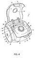
Fig. 4 is a perspective view showing a state where a lid body of the same main body part is opened. -
Fig. 5 is a perspective view showing the same electric vacuum cleaner. - A configuration of an electric vacuum cleaner according to an embodiment of the present invention will be described with reference to
Fig. 1 to Fig. 5 . - In
Fig. 5 , thereference numeral 11 denotes a so-called canister type electric vacuum cleaner, and thiselectric vacuum cleaner 11 includes atubular part 12, and a cleanermain body 13 as a main body part to which thetubular part 12 is removably connected. - The
tubular part 12 includes aconnecting tube part 15 having a tip end side bent forward with respect to the base end side to be connected to the cleanermain body 13, ahose body 16 with flexibility to be communicatively connected to the tip end side of the connectingtube part 15, ahand operation part 17 provided on the tip end side of thehose body 16, anextension tube 18 to be removably connected to the tip end side of thehand operation part 17, and afloor brush 19 as a suction port body to be removably connected to the tip end side of theextension tube 18. - On the
hand operation part 17, agrip part 21 projects to thehose body 16 side, and on thisgrip part 21, a plurality ofoperation setting buttons 22 are provided. - As shown in
Fig. 1 andFig. 4 , the cleanermain body 13 includes amain body case 25, and inside themain body case 25, apartition wall 26 is provided, and on the rear side of thepartition wall 26, an electric blower chamber not shown housing anelectric blower 27 and a cord reel chamber not shown housing a cord reel not shown around which apower cord 31 is wound are partitioned, and on the front side of thepartition wall 26, a main bodydust collecting chamber 35 which is communicatively connected to the suction side of theelectric blower 27 via a communication port not shown provided in thepartition wall 26 is partitioned, and in the main bodydust collecting chamber 35, adust collecting cup 36 as a dust collecting device is removably provided. - The
main body case 25 is made of, for example, a synthetic resin, and includes alower case 41 opened upward, anupper case 42 as an upper rear portion of thelower case 41 and covering the electric blower chamber and the cord reel chamber, and alidbody 43 axially supported turnably in the up-down direction with respect to theupper case 42 or thelower case 41 and capable of opening and closing the main bodydust collecting chamber 35. - The
lower case 41 has, on its rear side, a rear portioncurved surface 45 curved to the upper rear side on the lower surface facing a floor surface F as a surface to be cleaned, aflat surface 46 continuing to the front side of the rear portioncurved surface 45 at the substantially central position in the front-rear direction, and on the front side of theflat surface 46, a front portioncurved surface 47 continuing to the front side of theflat surface 46 and curved in a substantially arc shape to the upper front side. On both sides of the rear portioncurved surface 45 of thelower case 41, travelingwheels 51 with large diameters for traveling of thecleaner mainbody 13 are axially supported rotatably. Further, on the rear portioncurved surface 45 of thelower case 41, arear wheel 52 is provided. On the front portioncurved surface 47 of thelower case 41, afront wheel 53 is provided rotatably. - Each
traveling wheel 51 includes, as shown inFig. 1 to Fig. 3 , awheel portion 55 as a substantially disk-shaped traveling wheel main body, and aroller portion 56 attached to cover the entire outer periphery of thewheel portion 55. - The
wheel portion 55 is made of, for example, a hard synthetic resin, and the central portion serves as arotary shaft 57 axially supported rotatably on thelower case 41. - The
roller portion 56 is a portion which comes into contact with the floor surface F, and is made of a synthetic resin such as rubber or elastomer softer than thewheel portion 55. - The
rear wheel 52 includes an axially supportingportion 61 axially supported turnably on thelower case 41 and a rear wheelmain body 62 axially supported rotatably on the axially supportingportion 61. Therear wheel 52 is attached to the inside of a recessed attachingpart 63 attached to thelower case 41, and can advance to and withdraw from the lower case 41 (main body case 25). Further, therear wheel 52 is disposed at the substantially central position in the left-right width direction of the cleaner main body 13 (main body case 25). - The axially supporting
portion 61 is formed to have a quadrilateral shape in a plan view and a triangular shape in a side view, and is axially supported at its front end portion on a position on the front portion of the attachingpart 63 and posterior to therotary shafts 57 of thetraveling wheels 51 of thelower case 41, and axially supports the rear wheelmain body 62 on the rear end side. Therefore, the axially supportingportion 61 is arranged so that the rear side moves up and down according to turning as shown inFig. 2(a) and Fig. 2(b) . The position of the front end side of the axially supportingportion 61 axially supported turnably on thelower case 41 is lower than the line L connecting the central position of therotary shaft 57 of thetraveling wheel 51 and the center of the rotary shaft of the rear wheelmain body 62 in a side view. The inclination of the line L differs depending on the turning position of the axially supportingportion 61, and the inclination increases as the axially supportingportion 61 advances to the floor surface F side, and in the present embodiment, it is assumed that the front end side of the axially supportingportion 61 is axially supported on thelower case 41 at a position lower than the line L in the whole turning range of the axially supportingportion 61. Further, the axially supportingportion 61 is energized by acoil spring 65 as an energizing means so that the rear side projects downward, that is, toward the floor surface F side. Thiscoil spring 65 is disposed at a position anterior to the rear wheelmain body 62 and posterior to the front end portion of the axially supportingportion 61, that is, posterior to the portion where the axially supportingportion 61 is axially supported turnably on thelower case 41. Thiscoil spring 65 is preferably as far as possible from the portion where the axially supportingportion 61 is axially supported turnably on thelower case 41, that is, as far as possible from the front end portion of the axially supportingportion 61 so that therear wheel 52 is easily made project from themain body case 25. - The rear wheel
main body 62 has a horizontally-long columnar shape having an axial direction along the left-right direction, and to its outer peripheral surface, a raised-fabric cloth 67 is attached. By energizing the rear side of the axially supportingportion 61 to the floor surface F side by thecoil spring 65, the rear wheelmain body 62 is arranged to always be in elastic contact with the floor surface F when the cleanermain body 13 travels on the floor surface F. - The attaching
part 63 is fitted to ahole portion 69 having a quadrilateral shape in a plan view formed in thelower case 41. - The
front wheel 53 includes a front wheel axially supportingportion 71 fixed to thelower case 41, and a front wheelmain body 72 axially supported rotatably on the front wheel axially supportingportion 71. Thisfront wheel 53 is disposed at a substantially central position in the left-right width direction of the cleaner main body 13 (main body case 25) substantially symmetrical to therear wheel 52 with respect to a straight line connecting the central axes of therotary shafts 57 of thetraveling wheels rotary shafts 57 of thetraveling wheels 51 to the central axis of thefront wheel 53 is set to be substantially equal to the distance in the front-rear direction from therotary shafts 57 of thetraveling wheels 51 to the central axis of therear wheel 52. Specifically, thefront wheel 53 and therear wheel 52 are disposed at the front and rear sides at distances substantially equal to each other from therotary shafts 57 of thetraveling wheels 51. Further, thisfront wheel 53 is arranged so that the position of the lower end side is higher than the position of the lower end portion of theroller portion 56 as the lower end portion of thetraveling wheel 51, and does not come into contact with the floor surface F in a normal traveling state, and comes into contact with a bump D, etc., only when getting over the bump D. - The front wheel axially supporting
portion 71 includes a pair ofaxial support plates lower case 41. - The front wheel
main body 72 has a horizontally-long columnar shape having an axial direction along the left-right direction, and both end portions of the front wheel main body are axially supported on theaxial support plates fabric cloth 76 is attached. In addition, the front wheelmain body 72 has a width dimension substantially equal to the rear wheelmain body 62. - In the
upper case 42, a number of exhaust ports not shown which are communicatively connected to the downstream side of the electric blower chamber (cord reel chamber) are opened, and in a lateral side of these exhaust ports, a cord leading-outport 77 for leading thepower cord 31 to the outside of themain body case 25 is opened. On the upper portion of theupper case 42, ahandle 78 as a main body grip part for gripping the cleanermain body 13 is provided turnably in the front-rear direction. Further, on the upper portion of theupper case 42, acord rewind button 79 which enables rewinding of thepower cord 31 from the cord leading-outport 77 by rotating the cord reel is provided. - The
lid body 43 has a rear end side axially supported turnably, and a front end portion provided with aclamp 81 for engaging and disengaging thelid body 43 with and from thelower case 41. On thislid body 43, aslope portion 82 sloping to the front upper side is formed to have a circular shape, and on theslope portion 82, arotating part 84 including a mainbody suction port 83 to which the connectingtube part 15 of thetubular part 12 is connected is provided rotatably in the circumferential direction. - The
electric blower 27 operates in a predetermined operation mode set by thesetting button 22 and suctions dust together with air via thetubular part 12 by being supplied with power from a power supply via thepower cord 31, and is, for example, a heavy load heaviest in weight among various members disposed in themain body case 25. Thiselectric blower 27 is disposed inside the electric blower chamber so that the front side becomes the suction side and the rear side becomes the exhaust side, and is positioned eccentrically to the rear side as a whole of themain body case 25. Thiselectric blower 27 may be at least partially covered by, for example, a cover body. - The cord reel is a heavy load positioned at the lateral side of the
electric blower 27 and disposed inside the cord reel chamber, and positioned eccentrically to the rear side as a whole of themain body case 25. - As a result, the center of gravity of the cleaner
main body 13 is positioned on therotary shafts 57 of the travelingwheels 51. - On the other hand, as shown in
Fig. 1 , thedust collecting cup 36 traps dust included in suction air by centrifugal separation (cyclone separation), and includes a cupmain body part 85 as an outer case as a dust collecting device main body, aninside case 86 as an inner case provided removably inside the cupmain body part 85, acup lid 87 as a lid part provided turnably on the cupmain body part 85, and afilter part 88 removably attached to the cupmain body part 85. Inside the cupmain body part 85 of thedust collecting cup 36, a roughdust trapping chamber 91 which is a first dust collecting part as a dust collecting chamber for trapping rough dust such as dust balls, afilter attaching part 92 to which thefilter part 88 is attached, acommunication chamber 93 as an air path communicatively connected to the roughdust trapping chamber 91, and a finedust trapping chamber 94 serving as a second dust collecting part that is a dust storing chamber as a dust collecting chamber positioned below thefilter attaching part 92, are partitioned. - At the lower end portion of the cup
main body part 85, adust disposal port 95 which is communicatively connected to the roughdust trapping chamber 91 and the finedust trapping chamber 94 and is opened and closed by thecup lid 87 is formed. On a side portion of the cupmain body part 85, an open/close operation button 96 for opening and closing thecup lid 87 is disposed. On the upper portion of the cupmain body part 85, a cylindricalsuction tube part 98 which partitions a circularair suction port 97 communicatively connected to the roughdust trapping chamber 91 is formed. - To the entire
dust disposal port 95, a packing 99 as a sealing member is attached. - The
air suction port 97 circulates air including dust suctioned via thetubular part 12 as shown by the arrow A inside the roughdust trapping chamber 91, and is arranged to be connected airtightly to the downstream side of the mainbody suction port 83 by closing thelid body 43 in a state where the air suction port is attached to the main bodydust collecting chamber 35. - The
inside case 86 partitions acommunication chamber 93 between the inside case and the cupmain body part 85, andcommunication openings 101 which communicatively connect the roughdust trapping chamber 91 and thecommunication chamber 93 are opened in both side portions (only one is shown), and to eachcommunication opening 101, aside portion filter 102 as a filter is attached. Further, on the upper portion of theinside case 86, a cylindricalcommunication tube part 103 to be connected airtightly to the lower end side as the downstream side of thesuction tube part 98 is formed. Further, on the front portion of theinside case 86, afront wall part 104 projecting so as to cross a part of the air flow along the arrow A suctioned from theair suction port 97 into the roughdust trapping chamber 91 is formed. In the rear portion of theinside case 86, afilter attaching opening 105 as a rear portion opening which communicatively connects the roughdust trapping chamber 91 and thecommunication chamber 93 to thefilter attaching part 92 is opened, and to thisfilter attaching opening 105,amain filter 106 as a filtration filter is attached. Further, below thefilter attaching opening 105 of the rear portion of theinside case 86, aventilation opening 107 which communicatively connects the roughdust trapping chamber 91 and the finedust trapping chamber 94 is formed, and to thisventilation opening 107, alower portion filter 108 as a filter is attached. Above the ventilation opening of the rear portion of theinside case 86, aslope wall part 111 is formed to project to the rear lower side, and in thisslope wall part 111, a plurality ofopenings 112 which communicatively connect the finedust trapping chamber 94 and thefilter attaching part 92 are opened in the left-right width direction, and theseopenings 112 are opened and closed by flap-shapedshutters 113 as closing members. - The
front wall part 104 projects from the front side to the rear side and is opposed to thedust disposal port 95, and has acommunication opening 115 which communicatively connects the roughdust trapping chamber 91 and thecommunication chamber 93, and to thiscommunication opening 115, aventilation filter 116 as a filter is attached. - The
main filter 106 is a meshed filtration filter made of, for example, metal and having no unevenness on the upstream surface side and the downstream surface side, and is disposed at a position opposed to (facing) the lower end of thecommunication tube part 103 on the downstream side of theair suction port 97, and a suction air suctioned from theair suction port 97 is directly blown aslant to the main filter. - The
ventilation opening 107 is a vent hole for making smooth the actuation of theshutters 113 by suctioning air from the roughdust trapping chamber 91 side to the finedust trapping chamber 94 side when theshutters 113 are actuated by a negative pressure generated by driving of theelectric blower 27. - The upper end portion of each
shutter 113 is axially supported rotatably at a position on the upper end front side of theopenings 112, and the lower end side is a free end. - The
cup lid 87 is made of, for example, a synthetic resin and has, on one side, a pair of ribs not shown for axially supporting thecup lid 87 turnably on one side portion of the cupmain body part 85, and has, on the other side, a latching projection not shown having a claw shape as a latch part for latching thecup lid 87 onto the cupmain body part 85 side. Further, on thiscup lid 87, apacking receiving portion 121 with which a packing 99 on the lower portion of thedust disposal port 95 is brought into pressure contact is formed. - The
filter part 88 is a filter unit including, as a filter, a surface dust collecting filter which is a fine dust filter, that is, apleated filter 123, and afilter holding frame 124 which holds thepleated filter 123. - The
pleated filter 123 traps fine dust which was not trapped by thefilters pleated filter 123, a dust shaking-offpart 125 as a dust removing means which removes fine dust trapped by thepleated filter 123 by vibrating thepleated filter 123 is disposed. - The
filter attaching part 92 is a space formed to have a frame shape at the rear portion of the cupmain body part 85, and the rear end portion thereof becomes a dust collectingcup exhaust port 128 as a dust collecting device exhaust port having a substantially quadrilateral shape to be closed by thefilter part 88. - The
communication chamber 93 is an air path through which a part of air suctioned into the roughdust trapping chamber 91 flows to thepleated filter 123 without passing through themain filter 106, and is partitioned between the cupmain body part 85 and theinside case 86, and communicatively connected between the downstream side of the communication opening 101 (side portion filter 102) and the communication opening 115 (ventilation filter 116) and thefilter part 88 on the suction side of theelectric blower 27. - The fine
dust trapping chamber 94 is a space for storing fine dust removed from thepleated filter 123 by the dust shaking-offpart 125 via theopenings 112. - Next, operations of the above-described embodiment will be described.
- When cleaning, first, an operator opens the
lid body 43 of the cleanermain body 13, attaches thedust collecting cup 36 to the main bodydust collecting chamber 35, and closes thelid body 43. At this time, the operator communicatively connects thehose body 16 to the mainbody suction port 83 on the upper side via the connectingtube part 15, and communicatively connects theextension tube 18 and thefloor brush 19 to the tip end side of thehose body 16 in order. - Further, the operator pulls the
power cord 31 out from the cleanermain body 13 and plugs it in a socket not shown. - Thereafter, when the operator grips the
grip part 21 and operates apredetermined setting button 22, theelectric blower 27 is driven according to an operation mode set by thesetting button 22. According to driving of theelectric blower 27,shutters 113 are adsorbed to the front face side of theslope wall part 111 by air that passed through the ventilation opening 107 (lower portion filter 108) to close theopenings 112, so that fine dust trapped in the finedust trapping chamber 94 is not suctioned out from theopenings 112 to the filter attaching part 92 (pleated filter 123) side. - Next, the operator makes the
floor brush 19 travel back and forth on the floor surface F while making the cleanermain body 13 travel on the floor surface F by gripping thegrip part 21, and accordingly, dust is suctioned together with air from the tip end side of thefloor brush 19 by a negative pressure generated by theelectric blower 27. - At this time, by energizing the rear side of the
axially supporting portion 61 so as to turn down by thecoil spring 65, therear wheel 52 advances to the floor surface F side from thelower case 41 and the raised-fabric cloth 67 of the rear wheelmain body 62 comes into contact with the floor surface F, so that the cleanermain body 13 is supported at three points of therear wheel 52 and the travelingwheels 51 and stably travels straight. The rear wheelmain body 62 is in elastic contact with the floor surface F due to thecoil spring 65, so that vibrations in the up-down direction caused during traveling of the cleanermain body 13 are absorbed by withdrawal of therear wheel 52 into the attachingpart 63 of themain body case 25 in response to contraction of thecoil spring 65 according to the vibrations, and the rear wheelmain body 62 comes into contact with the floor surface F at a proper contact pressure. Further, when the cleanermain body 13 goes over a bump D such as an obstacle during traveling, the front wheelmain body 72 of thefront wheel 53 comes into contact with the bump D and makes it easy to get over the bump D, and the rear side of theaxially supporting portion 61 of therear wheel 52 turns up along the upper surface of the bump D, etc., against energization of thecoil spring 65, and accordingly, the rear wheel 52 (rear wheel main body 62) is prevented from being caught on the bump D. - When the operator pulls the
tubular part 12 laterally with respect to the cleanermain body 13, one travelingwheel 51 rotates forward and the other travelingwheel 51 rotates reversely, and accordingly, the cleanermain body 13 turns following the pulling direction of thetubular part 12. - Air suctioned together with dust from the
floor brush 19 becomes suction air, and carries dust from the mainbody suction port 83 to thedust collecting cup 36 via theextension tube 18 and the hose body 16 (connecting tube part 15). - In this
dust collecting cup 36, suction air which is suctioned from the mainbody suction port 83 to theair suction port 97 is suctioned substantially straight to the roughdust trapping chamber 91 along the opening direction of theair suction port 97 via thesuction tube part 98 and thecommunication tube part 103, and directly blown aslant to the upstream side surface of themain filter 106 to always remove and drop dust adhering to themain filter 106. - Further, the suction air blown to the
main filter 106 turns to the front portion upper side from the rear portion lower side in the arrow A direction inside the roughdust trapping chamber 91 while removing dust adhering to themain filter 106, and then passes through themain filter 106 and flows to thefilter attaching part 92 while dust is trapped from the suction air. By this turning, rough dust such as dust balls included in the suction air is centrifugally separated (cyclone-separated) by the centrifugal force, and stored while being compressed toward the lower side of thefront wall part 104. - From a part of the suction air, dust is trapped when it passes through the
side portion filter 102 and theventilation filter 116 and flows to thecommunication chamber 93. - From the suction air which has passed through the
main filter 106 or the communication chamber 93 (side portion filter 102 and the ventilation filter 116), fine dust which is not trapped by thefilters pleated filter 123. - Thereafter, the suction air is suctioned into the
electric blower 27 via the communication port of thepartition wall 26, and passes through theelectricblower 27 and becomes exhaust air, and is exhausted to the outside of the cleanermain body 13 from the exhaust port of themain body case 25. - To finish cleaning, the operator operates a
predetermined setting button 22 to stop theelectric blower 27. In response to this stop of theelectric blower 27, theshutters 113 turn to the front lower side due to their own weights to open theopenings 112. In this state, the dust shaking-offpart 125 operates for a predetermined time to drop and remove fine dust trapped by thepleated filter 123, and the fine dust is trapped in the finedust trapping chamber 94 via theopenings 112. The dust shaking-offpart 125 may also be operated, for example, immediately before starting theelectric blower 27. - Thereafter, the operator operates the
cord rewind button 79 to rewind thepower cord 31 unplugged from the socket around the cord reel from the cord leading-out port 77. - When trapped dust not less than a predetermined amount is accumulated in the
dust collecting cup 36, the operator opens thelid body 43 of the cleanermain body 13, removes thedust collecting cup 36 from the main bodydust collecting chamber 35, and operates the open/close operation button 96 to open thecup lid 87 above a garbage box, etc. , and accordingly, rough dust trapped in the roughdust trapping chamber 91 and fine dust trapped in the finedust trapping chamber 94 are disposed of from thedust disposal port 95. - Further, when the
side portion filter 102 and theventilation filter 116, etc., are clogged, the operator pulls out theinside case 86 downward from thedust disposal port 95 and removes it from the cupmain body part 85, and maintains thefilters main filter 106 is clogged due to long-term continuous use although it is rarely clogged, the operator removes dust from the filter. - Thereafter, the operator closes the
cup lid 87 in a state where theinside case 86 is attached to the cupmain body part 85, attaches thedust collecting cup 36 again to the main bodydust collecting chamber 35 of the cleanermain body 13, and closes thelid body 43. - As described above, in the embodiment described above, the
rear wheel 52 which can advance to and withdraw from the floor surface F and can come into contact with the floor surface F in an advanced state at a position posterior to therotary shafts 57 of the travelingwheels 51 is energized by thecoil spring 65 in a direction of advancing to the floor surface - Therefore, for example, when the rear wheel or the like is provided so as to project from the main body case, while the straight traveling performance of the cleaner
main body 13 can be improved, the rear wheel becomes resistant and deteriorates the turnability when the cleanermain body 13 turns, and on the other hand, according to the embodiment described above, therear wheel 52 comes into elastic contact with the floor surface F, so that therear wheel 52 comes into contact with the floor surface F at a proper contact pressure by advancing and withdrawing as appropriate, so that, without deteriorating the turnability of the cleanermain body 13 by the travelingwheels 51, the straight traveling performance can be made higher than in the case where the cleaner main body travels only by the travelingwheels 51. - Further, only one
rear wheel 52 is provided at the central position in the left-right width direction of the cleanermain body 13, so that the frictional resistance with the floor surface F can be minimized while the straight traveling balance is maintained, and turnability can be secured. - The
rear wheel 52 is always in elastic contact with the floor surface F in the traveling state where the travelingwheels 51 of the cleanermain body 13 are grounded on the floor surface F, so that therear wheel 52 does not float up from the floor surface F and the straight traveling performance can be reliably improved. - Further, by axially supporting the rear wheel
main body 62 of therear wheel 52 on theaxially supporting portion 61 axially supported on themain body case 25 turnably in the direction of advancing and withdrawing the rear wheelmain body 62 to and from the floor surface F at a position anterior to the rear wheelmain body 62, when the cleanermain body 13 travels forward, theaxially supporting portion 61 is hardly caught on the floor surface F and therear wheel 52 more easily turns in comparison with the case where, for example, the turning shaft of the axially supporting portion is positioned posterior to the rear wheel main body. - The
axially supporting portion 61 is axially supported lower than the line connecting therotary shaft 57 of the travelingwheel 51 and the rotary shaft of the rear wheelmain body 62 in a side view, so that the inclination angle of theaxially supporting portion 61 with respect to the floor surface F becomes smaller, the contact resistance between the rear wheelmain body 62 and the floor surface F is reduced, and therear wheel 52 turns more easily. - Further, by providing the
front wheel 53 rotatably anterior to therotary shafts 57 of the travelingwheels 51 of themain body case 25, in the case where a bump D such as an obstacle is on the floor surface when the cleanermain body 13 travels forward, thefront wheel 53 collides with the bump D and rotates, and accordingly, the cleaner main body more easily gets over the bump D, so that the cleaning operability is improved. - Further, the
roller portions 56 which come into contact with the floor surface F of the travelingwheels 51 are made of a soft synthetic resin, and therear wheel 52 has a raised-fabric cloth 67 on the outer peripheral surface of the rear wheelmain body 62 which comes into contact with the floor surface F, and accordingly, the travelingwheels 51 hardly slip on the comparatively flat floor surface F, and therear wheel 52 more easily slides on the floor surface F, so that while the straight traveling performance is secured by therear wheel 52, therear wheel 52 hardly becomes more resistant when turning, so that the turnability can be improved. - By providing the raised-
fabric cloth 67 on the outer periphery of the rear wheelmain body 62 of therear wheel 52 and providing the raised-fabric cloth 76 on the outer periphery of the front wheelmain body 72 of thefront wheel 53, dust on the floor surface F can be wiped off by these raised-fabric cloths - In the embodiment described above, pluralities of
rear wheels 52 andfront wheels 53 may be provided. In this case, in order to stably support the cleanermain body 13, the rear wheels and front wheels are preferably disposed substantially uniformly in the left-right width direction, that is, symmetrically in the left-right width direction. - The
front wheel 53 may not be provided as long as the cleaner main body can get over the bump D on the floor surface F. - As a dust collecting device, the
dust collecting cup 36 for centrifugal separation of dust is used, however, a configuration in which dust is collected in a paper pack or a configuration in which dust is collected by linear separation, etc., can be arbitrarily selected. Therefore, the internal configuration, etc., of the cleanermain body 13 are not limited to the configuration described above. - The present invention can be preferably applied to, for example, domestic vacuum cleaners.
-
- 11
- Electric vacuum cleaner
- 13
- Cleaner main body as main body part
- 25
- Main body case
- 27
- Electric blower
- 51
- Traveling wheel
- 52
- Rear wheel
- 53
- Front wheel
- 57
- Rotary shaft
- 61
- Axially supporting portion
- 62
- Rear wheel main body
- 67
- Raised-fabric cloth
- F
- Floor surface as surface to be cleaned
Claims (6)
- An electric vacuum cleaner comprising:a main body part including a main body case and an electric blower housed in the main body case;traveling wheels provided rotatably at positions on both sides of the main body case below the center of gravity of the main body part; anda rear wheel which is provided so as to advance to and withdraw from a surface to be cleaned posterior to the rotary shafts of the traveling wheels of the main body case, and is energized in a direction of advancing to the surface to be cleaned, and can come into contact with the surface to be cleaned in an advanced state.
- The electric vacuum cleaner according to Claim 1, wherein the rear wheel is always in elastic contact with the surface to be cleaned in a traveling state where the traveling wheels of the main body part are grounded on the surface to be cleaned.
- The electric vacuum cleaner according to Claim 1 or 2, wherein
the rear wheel includes:a rear wheel main body contactable with the surface to be cleaned; andan axially supporting portion which axially supports the rear wheel main body rotatably, and is axially supported at a position anterior to the rear wheel main body on the main body case turnably in a direction of advancing and withdrawing the rear wheel main body to and from the surface to be cleaned. - The electric vacuum cleaner according to Claim 3, wherein the axially supporting portion is axially supported lower than the line connecting a rotary shaft of the traveling wheel and a rotary shaft of the rear wheel main body in a side view.
- The electric vacuum cleaner according to any one of Claims 1 to 4, comprising:a front wheel provided rotatably anterior to the rotary shafts of the traveling wheels of the main body case.
- The electric vacuum cleaner according to any one of Claims 1 to 5, wherein
at least portions of the traveling wheels which come into contact with the surface to be cleaned are made of a resin, and
the rear wheel has a raised-fabric cloth on a portion which comes into contact with the surface to be cleaned.
Applications Claiming Priority (2)
| Application Number | Priority Date | Filing Date | Title |
|---|---|---|---|
| JP2008171640A JP5430886B2 (en) | 2008-06-30 | 2008-06-30 | Electric vacuum cleaner |
| PCT/JP2009/059755 WO2010001674A1 (en) | 2008-06-30 | 2009-05-28 | Electric cleaner |
Publications (2)
| Publication Number | Publication Date |
|---|---|
| EP2305089A1 true EP2305089A1 (en) | 2011-04-06 |
| EP2305089A4 EP2305089A4 (en) | 2016-01-20 |
Family
ID=41465777
Family Applications (1)
| Application Number | Title | Priority Date | Filing Date |
|---|---|---|---|
| EP09773252.3A Withdrawn EP2305089A4 (en) | 2008-06-30 | 2009-05-28 | Electric cleaner |
Country Status (6)
| Country | Link |
|---|---|
| EP (1) | EP2305089A4 (en) |
| JP (1) | JP5430886B2 (en) |
| KR (1) | KR101261145B1 (en) |
| CN (1) | CN102014720B (en) |
| RU (1) | RU2453261C1 (en) |
| WO (1) | WO2010001674A1 (en) |
Cited By (1)
| Publication number | Priority date | Publication date | Assignee | Title |
|---|---|---|---|---|
| DE112017001064B4 (en) | 2016-02-29 | 2023-09-21 | Lg Electronics Inc. | Vacuum cleaner |
Families Citing this family (26)
| Publication number | Priority date | Publication date | Assignee | Title |
|---|---|---|---|---|
| JP5159934B1 (en) * | 2011-09-29 | 2013-03-13 | シャープ株式会社 | Cleaning robot |
| CN105383537B (en) * | 2014-07-03 | 2019-06-21 | 明门香港股份有限公司 | baby carriage device |
| JP2017029564A (en) * | 2015-08-05 | 2017-02-09 | 三菱電機株式会社 | Electric vacuum cleaner |
| TWI643596B (en) | 2016-02-29 | 2018-12-11 | Lg電子股份有限公司 | Vacuum cleaner |
| KR101872101B1 (en) * | 2016-08-25 | 2018-06-27 | 엘지전자 주식회사 | Vacuum cleaner |
| TWI664944B (en) | 2016-02-29 | 2019-07-11 | Lg電子股份有限公司 | Vacuum cleaner |
| DE202017000985U1 (en) | 2016-02-29 | 2017-05-29 | Lg Electronics Inc. | vacuum cleaner |
| TWI653962B (en) | 2016-02-29 | 2019-03-21 | Lg電子股份有限公司 | Vacuum cleaner |
| KR101872099B1 (en) * | 2016-08-25 | 2018-06-27 | 엘지전자 주식회사 | Vacuum cleaner |
| TWI637718B (en) | 2016-02-29 | 2018-10-11 | Lg電子股份有限公司 | Vacuum cleaner |
| TWI641353B (en) | 2016-02-29 | 2018-11-21 | Lg電子股份有限公司 | Vacuum cleaner |
| TWI636758B (en) | 2016-02-29 | 2018-10-01 | Lg電子股份有限公司 | Vacuum cleaner |
| GB2564035B8 (en) | 2016-02-29 | 2021-07-07 | Lg Electronics Inc | Vacuum cleaner |
| TWI664943B (en) | 2016-02-29 | 2019-07-11 | Lg電子股份有限公司 | Vacuum cleaner |
| KR101872100B1 (en) * | 2016-08-25 | 2018-06-27 | 엘지전자 주식회사 | Vacuum cleaner |
| WO2017150862A1 (en) | 2016-02-29 | 2017-09-08 | 엘지전자 주식회사 | Vacuum cleaner |
| WO2017150829A1 (en) * | 2016-02-29 | 2017-09-08 | 엘지전자 주식회사 | Vacuum cleaner |
| AU2017227412B2 (en) | 2016-02-29 | 2020-01-23 | Lg Electronics Inc. | Vacuum cleaner |
| KR101872102B1 (en) * | 2016-08-25 | 2018-06-27 | 엘지전자 주식회사 | Vacuum cleaner and control method thereof |
| DE202017000984U1 (en) | 2016-02-29 | 2017-05-29 | Lg Electronics Inc. | vacuum cleaner |
| KR101852407B1 (en) * | 2016-08-25 | 2018-06-11 | 엘지전자 주식회사 | Vacuum cleaner |
| TWI643597B (en) | 2016-02-29 | 2018-12-11 | Lg電子股份有限公司 | Vacuum cleaner |
| DE202017002619U1 (en) | 2016-05-20 | 2017-08-04 | Lg Electronics Inc. | vacuum cleaner |
| KR101952634B1 (en) * | 2016-08-25 | 2019-02-27 | 엘지전자 주식회사 | Vacuum cleaner |
| JP6875837B2 (en) * | 2016-11-30 | 2021-05-26 | 東芝ライフスタイル株式会社 | Vacuum cleaner |
| CN113662473A (en) * | 2021-09-28 | 2021-11-19 | 林鑫森 | All-weather uninterrupted dust collector |
Family Cites Families (11)
| Publication number | Priority date | Publication date | Assignee | Title |
|---|---|---|---|---|
| US4852705A (en) * | 1988-07-22 | 1989-08-01 | Cowan Jr Samuel C | Case with extendable wheels and handle |
| JPH0426407A (en) * | 1990-05-22 | 1992-01-29 | Sanyo Electric Co Ltd | Flexible wheel device for cleaner |
| JPH04329918A (en) * | 1991-04-30 | 1992-11-18 | Tokyo Electric Co Ltd | vacuum cleaner |
| JPH04343815A (en) | 1991-05-22 | 1992-11-30 | Sharp Corp | Floor moving type vacuum cleaner |
| JP3113397B2 (en) * | 1992-07-16 | 2000-11-27 | 三洋電機株式会社 | Electric vacuum cleaner |
| JP2574272Y2 (en) * | 1992-10-28 | 1998-06-11 | 株式会社テック | Electric vacuum cleaner |
| JPH07236599A (en) * | 1994-03-01 | 1995-09-12 | Matsushita Electric Ind Co Ltd | Vacuum cleaner |
| JPH0856873A (en) * | 1994-08-17 | 1996-03-05 | Mitsubishi Electric Home Appliance Co Ltd | Electric vacuum cleaner |
| JP2000354570A (en) * | 1999-06-15 | 2000-12-26 | Toshiba Tec Corp | Vacuum cleaner and its suction body |
| KR20040023285A (en) * | 2002-09-11 | 2004-03-18 | 엘지전자 주식회사 | Caster for vacuum cleaner and main body having the same |
| JP2007130129A (en) * | 2005-11-09 | 2007-05-31 | Sanyo Electric Co Ltd | Self-propelled vacuum cleaner |
-
2008
- 2008-06-30 JP JP2008171640A patent/JP5430886B2/en not_active Expired - Fee Related
-
2009
- 2009-05-28 CN CN200980116232.0A patent/CN102014720B/en not_active Expired - Fee Related
- 2009-05-28 EP EP09773252.3A patent/EP2305089A4/en not_active Withdrawn
- 2009-05-28 WO PCT/JP2009/059755 patent/WO2010001674A1/en not_active Ceased
- 2009-05-28 KR KR1020107019947A patent/KR101261145B1/en not_active Expired - Fee Related
- 2009-05-28 RU RU2010150968/12A patent/RU2453261C1/en active
Non-Patent Citations (1)
| Title |
|---|
| See references of WO2010001674A1 * |
Cited By (1)
| Publication number | Priority date | Publication date | Assignee | Title |
|---|---|---|---|---|
| DE112017001064B4 (en) | 2016-02-29 | 2023-09-21 | Lg Electronics Inc. | Vacuum cleaner |
Also Published As
| Publication number | Publication date |
|---|---|
| WO2010001674A1 (en) | 2010-01-07 |
| JP2010005341A (en) | 2010-01-14 |
| CN102014720A (en) | 2011-04-13 |
| KR101261145B1 (en) | 2013-05-06 |
| KR20100123861A (en) | 2010-11-25 |
| CN102014720B (en) | 2014-07-30 |
| RU2453261C1 (en) | 2012-06-20 |
| EP2305089A4 (en) | 2016-01-20 |
| JP5430886B2 (en) | 2014-03-05 |
Similar Documents
| Publication | Publication Date | Title |
|---|---|---|
| CN102014720B (en) | Electric cleaner | |
| KR100731672B1 (en) | Vacuum cleaners | |
| KR20070008445A (en) | cleaner | |
| KR20020076239A (en) | Device for a vacuum cleaner | |
| JP5330909B2 (en) | Dust collector and vacuum cleaner | |
| JP2005131135A (en) | Electric vacuum cleaner | |
| JP6430112B2 (en) | Electric vacuum cleaner | |
| JP2009279339A (en) | Vacuum cleaner | |
| JP6271220B2 (en) | Electric vacuum cleaner | |
| JP5388717B2 (en) | Dust collector and vacuum cleaner | |
| KR101282536B1 (en) | Dust collecting apparatus and electric cleaner | |
| JP4928900B2 (en) | Vacuum cleaner | |
| JP2009201568A (en) | Electric vacuum cleaner | |
| JP7005212B2 (en) | Vacuum cleaner | |
| JP5567394B2 (en) | Dust collector and vacuum cleaner | |
| JP5172415B2 (en) | Electric vacuum cleaner | |
| JP5666849B2 (en) | Dust separator and vacuum cleaner | |
| JP4118289B2 (en) | Dust collector and vacuum cleaner | |
| JP4664744B2 (en) | Electric vacuum cleaner | |
| JP2021094278A (en) | Suction port body and vacuum cleaner | |
| JP2011010742A (en) | Dust collector and vacuum cleaner | |
| JP2007252641A (en) | Electric vacuum cleaner | |
| JP2004298494A (en) | Electric vacuum cleaner | |
| JP2011004933A (en) | Dust collecting device and vacuum cleaner | |
| JP2008099813A (en) | Electric vacuum cleaner |
Legal Events
| Date | Code | Title | Description |
|---|---|---|---|
| PUAI | Public reference made under article 153(3) epc to a published international application that has entered the european phase |
Free format text: ORIGINAL CODE: 0009012 |
|
| 17P | Request for examination filed |
Effective date: 20110124 |
|
| AK | Designated contracting states |
Kind code of ref document: A1 Designated state(s): AT BE BG CH CY CZ DE DK EE ES FI FR GB GR HR HU IE IS IT LI LT LU LV MC MK MT NL NO PL PT RO SE SI SK TR |
|
| AX | Request for extension of the european patent |
Extension state: AL BA RS |
|
| DAX | Request for extension of the european patent (deleted) | ||
| RA4 | Supplementary search report drawn up and despatched (corrected) |
Effective date: 20151222 |
|
| RIC1 | Information provided on ipc code assigned before grant |
Ipc: A47L 9/00 20060101AFI20151216BHEP |
|
| STAA | Information on the status of an ep patent application or granted ep patent |
Free format text: STATUS: THE APPLICATION HAS BEEN WITHDRAWN |
|
| 18W | Application withdrawn |
Effective date: 20160308 |