JP2009201568A - Vacuum cleaner - Google Patents

Vacuum cleaner Download PDF

Info

Publication number
JP2009201568A
JP2009201568A JP2008044507A JP2008044507A JP2009201568A JP 2009201568 A JP2009201568 A JP 2009201568A JP 2008044507 A JP2008044507 A JP 2008044507A JP 2008044507 A JP2008044507 A JP 2008044507A JP 2009201568 A JP2009201568 A JP 2009201568A
Authority
JP
Japan
Prior art keywords
dust
filter
opening
vacuum cleaner
electric blower
Prior art date
Legal status (The legal status is an assumption and is not a legal conclusion. Google has not performed a legal analysis and makes no representation as to the accuracy of the status listed.)
Pending
Application number
JP2008044507A
Other languages
Japanese (ja)
Inventor
Kiyoshi Ebe
清 江部
Mitsuru Watanabe
満 渡邉
Current Assignee (The listed assignees may be inaccurate. Google has not performed a legal analysis and makes no representation or warranty as to the accuracy of the list.)
Toshiba Corp
Toshiba Lifestyle Products and Services Corp
Original Assignee
Toshiba Corp
Toshiba Consumer Electronics Holdings Corp
Toshiba Home Appliances Corp
Priority date (The priority date is an assumption and is not a legal conclusion. Google has not performed a legal analysis and makes no representation as to the accuracy of the date listed.)
Filing date
Publication date
Application filed by Toshiba Corp, Toshiba Consumer Electronics Holdings Corp, Toshiba Home Appliances Corp filed Critical Toshiba Corp
Priority to JP2008044507A priority Critical patent/JP2009201568A/en
Publication of JP2009201568A publication Critical patent/JP2009201568A/en
Pending legal-status Critical Current

Links

Images

Abstract

<P>PROBLEM TO BE SOLVED: To provide a vacuum cleaner wherein dust once removed is prevented from sticking to a pleated filter body again. <P>SOLUTION: An opening/closing body 61 for covering the downstream side of a mesh filter 60 when an electric blower is stopped is provided. The movement to the side of the mesh filter 60 of fine dust removed from the pleated filter body 73 by a dust removal means 75 is blocked by the opening/closing body 61 covering the mesh filter 60. The fine dust once removed from the pleated filter body 73 is prevented from passing through the mesh filter 60 again and sticking to the pleated filter body 73 again by the drive of the electric blower. <P>COPYRIGHT: (C)2009,JPO&INPIT

Description

本発明は、フィルタに捕集した塵埃を除去する除塵手段を備えた電気掃除機に関する。   The present invention relates to a vacuum cleaner provided with dust removing means for removing dust collected by a filter.

従来、この種の電気掃除機は、電動送風機を収容した掃除機本体を備えている。この掃除機本体には、電動送風機に給電するための電源コードを巻回したコードリールが後部に収容されているとともに、電動送風機の吸込側に連通して集塵装置(集塵部)である集塵カップが全部に着脱可能に設けられている。また、この集塵カップの吸込側には、ホース体、延長管および吸込口体としての床ブラシを順次備えた管部が着脱可能に接続される。そして、集塵カップは、吸込口と排気口とを備えたカップ本体の内部に、吸込口に連通する第1集塵部および第2集塵部がそれぞれ別個に区画されている。第1集塵部は、例えば粗塵を捕集する集塵部であり、第2集塵部の下流側で排気口の上流側に連通する開口が設けられ、この開口にメッシュ状のフィルタが設けられている。また、第2集塵部は、下流側が排気口に連通し、例えば細塵を捕集するプリーツ状などの細塵フィルタが排気口に取り付けられている。この細塵フィルタには、所定のタイミング、例えば掃除機本体から導出した電源コードをコードリールに巻き取る際などにこの細塵フィルタに振動を与えて、この細塵フィルタに捕集した細塵を除去する除塵手段が設けられている。そして、カップ本体には、細塵フィルタから除塵手段により除去された細塵を捕集する第3集塵部が、細塵フィルタの下方に区画されている(例えば、特許文献1参照。)。
特開2006−6406号公報(第7−8頁、図3−4)
Conventionally, this type of vacuum cleaner includes a vacuum cleaner body that houses an electric blower. In this vacuum cleaner main body, a cord reel wound with a power cord for supplying electric power to the electric blower is accommodated in the rear part, and communicates with the suction side of the electric blower and is a dust collecting device (dust collecting part). A dust collection cup is detachably provided on the whole. In addition, a pipe part that is sequentially provided with a hose body, an extension pipe, and a floor brush as a suction port body is detachably connected to the suction side of the dust collection cup. In the dust collection cup, a first dust collection unit and a second dust collection unit communicating with the suction port are separately defined inside a cup body having a suction port and an exhaust port. The first dust collecting unit is, for example, a dust collecting unit that collects coarse dust. An opening communicating with the upstream side of the exhaust port is provided on the downstream side of the second dust collecting unit, and a mesh filter is provided in the opening. Is provided. In addition, the second dust collecting unit is connected to the exhaust port on the downstream side, and a fine dust filter such as a pleat for collecting fine dust is attached to the exhaust port. The fine dust filter vibrates the fine dust filter at a predetermined timing, for example, when a power cord led out from the vacuum cleaner body is wound on a cord reel, and the fine dust collected in the fine dust filter is collected. A dust removing means for removing is provided. And the 3rd dust collection part which collects the fine dust removed by the dust removal means from the fine dust filter is divided by the cup main body under the fine dust filter (for example, refer patent document 1).
JP 2006-6406 A (page 7-8, FIG. 3-4)

しかしながら、上述の電気掃除機では、除塵手段により細塵フィルタから除去された細塵が開口側へと落下することがあり、このように開口側へと落下した細塵が、電気掃除機を再度起動させた際に、細塵フィルタに付着してしまうという問題点を有している。   However, in the above vacuum cleaner, fine dust removed from the fine dust filter by the dust removing means may fall to the opening side, and the fine dust that has dropped to the opening side in this way causes the vacuum cleaner to be reopened. When activated, it has a problem of adhering to the fine dust filter.

本発明は、このような点に鑑みなされたもので、一旦除去した塵埃のフィルタへの再付着を防止した電気掃除機を提供することを目的とする。   This invention is made | formed in view of such a point, and it aims at providing the vacuum cleaner which prevented the reattachment to the filter of the dust once removed.

本発明は、掃除機本体の電動送風機の吸込側に位置して設けられた第1フィルタと、掃除機本体の電動送風機の吸込側でかつ第1フィルタよりも下流側に位置して設けられ、この第1フィルタよりも目が細かい第2フィルタと、この第2フィルタに捕集した塵埃を除去する除塵手段と、この除塵手段により第2フィルタから除去した塵埃の第1フィルタ側への移動を阻止する阻止手段とを具備したものである。   The present invention is provided on the suction side of the electric blower of the cleaner main body and located on the suction side of the electric blower of the cleaner main body and on the downstream side of the first filter, A second filter having a finer mesh than the first filter, dust removing means for removing dust collected by the second filter, and movement of dust removed from the second filter by the dust removing means to the first filter side. And blocking means for blocking.

本発明によれば、除塵手段により第2フィルタから除去した塵埃の第1フィルタ側への移動を阻止手段により阻止することで、この第2フィルタから一旦除去した塵埃が電動送風機の駆動により第1フィルタを再度通過して第2フィルタへ再付着することを防止できる。   According to the present invention, the dust removed from the second filter by the dust removing means is prevented from moving to the first filter side by the preventing means, so that the dust once removed from the second filter is driven by the electric blower. It can be prevented from passing through the filter again and reattaching to the second filter.

以下、本発明の一実施の形態の電気掃除機の構成を図1ないし図7を参照して説明する。   Hereinafter, the configuration of a vacuum cleaner according to an embodiment of the present invention will be described with reference to FIGS. 1 to 7.

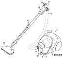
図6および図7において、1は掃除機本体で、この掃除機本体1は、電動送風機2を収容した本体ケース3と、この本体ケース3に後部が回動可能に軸支された上下方向に開閉可能な蓋体4と、電動送風機2の上流側に位置し本体ケース3に着脱可能な集塵装置としての集塵容器5とを備え、電動送風機2の駆動にて生じる吸込風とともに吸い込んだ塵埃を集塵容器5で遠心分離して集塵する、いわゆるサイクロン式の電気掃除機であり、被掃除面としての床面上を走行可能である。   6 and 7, reference numeral 1 denotes a vacuum cleaner main body. The vacuum cleaner main body 1 includes a main body case 3 housing an electric blower 2 and a vertical direction in which a rear portion is pivotally supported by the main body case 3 so as to be rotatable. A lid 4 that can be opened and closed, and a dust collecting container 5 as a dust collecting device that is located on the upstream side of the electric blower 2 and can be attached to and detached from the main body case 3, and sucked together with the suction air generated by driving the electric blower 2 This is a so-called cyclonic vacuum cleaner that collects dust by centrifugal separation in a dust collecting container 5, and can travel on the floor as a surface to be cleaned.

本体ケース3には、電動送風機2の下方に、図示しない商用交流電源から電動送風機2などへと給電可能にする図示しない電源コードを巻回したコードリールが収容されている。また、本体ケース3の前部には、皿状の載置部8が設けられている。この載置部8は、集塵容器5が着脱可能に載置され、蓋体4を閉じた際にこの蓋体4との間で集塵容器5を挟持固定可能な部分である。   The main body case 3 accommodates a cord reel around a power cord (not shown) that enables power supply from a commercial AC power source (not shown) to the electric blower 2 and the like below the electric blower 2. A dish-shaped placement portion 8 is provided at the front portion of the main body case 3. The mounting portion 8 is a portion on which the dust collecting container 5 is detachably mounted, and when the lid 4 is closed, the dust collecting container 5 can be sandwiched and fixed between the lid 4.

蓋体4は、前部に管部11が設けられ、この管部11の先端部である前部が、空気を吸引するホース接続口12となり、管部11の基端部である後部が、載置部8に固定される集塵容器5の吸込側に連通する接続開口13となっている。   The lid 4 is provided with a tube portion 11 at the front portion, the front portion which is the tip portion of the tube portion 11 becomes a hose connection port 12 for sucking air, and the rear portion which is the base end portion of the tube portion 11 is A connection opening 13 communicates with the suction side of the dust collecting container 5 fixed to the mounting portion 8.

ホース接続口12には、可撓性を有し湾曲可能な細長略円筒状の集塵ホース15の基端部が連通接続されている。この集塵ホース15の先端部には、電動送風機2の動作モードなどが選択可能な手元操作部16が設けられている。この手元操作部16には、作業者が把持する把持部17が突設され、この把持部17には、電動送風機2などを複数の動作モードに設定する複数の操作スイッチ18が設けられている。   The hose connection port 12 is connected to the base end portion of an elongated substantially cylindrical dust collection hose 15 that is flexible and bendable. At the tip of the dust collecting hose 15, a hand operating unit 16 capable of selecting the operation mode of the electric blower 2 is provided. The hand operating section 16 is provided with a gripping section 17 that is gripped by an operator, and the gripping section 17 is provided with a plurality of operation switches 18 for setting the electric blower 2 and the like to a plurality of operation modes. .

また、手元操作部16の先端には、伸縮可能な細長略円筒状の延長管21が着脱可能に連通接続されている。さらに、この延長管21の先端には、例えば室内の床面の絨毯などの上に載置され、絨毯などの上の塵埃を吸い込む床ブラシである吸込口体22が着脱可能に連通接続されている。   In addition, a telescopic elongated cylindrical extension tube 21 is detachably connected to the distal end of the hand operation unit 16. Further, the extension pipe 21 is detachably connected to a suction port body 22 that is placed on, for example, a carpet on the floor of the room and is a floor brush that sucks dust on the carpet. Yes.

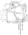
集塵容器5は、図1ないし図5に示すように、装置本体としての集塵容器本体25と、この集塵容器本体25の上部に着脱可能の平面視略円形状の風路形成体26と、集塵容器本体25の下部に開閉可能に軸支された集塵装置蓋部としての底蓋27と、集塵容器本体25の後部に着脱可能の細塵分離体としてのプリーツフィルタ部28とを備えている。   As shown in FIGS. 1 to 5, the dust collecting container 5 includes a dust collecting container main body 25 as an apparatus main body, and a substantially circular air passage forming body 26 that can be attached to and detached from the upper portion of the dust collecting container main body 25. A bottom cover 27 as a dust collector lid that is pivotally supported at the bottom of the dust container main body 25 and a pleat filter part 28 as a fine dust separator that can be attached to and detached from the rear of the dust container main body 25 And.

集塵容器本体25は、集塵容器5の前部から両側部に亘る外郭を形成する壁部31と、この壁部31の上部を閉塞して傾斜状に連続する傾斜壁部としての上壁部32と、この上壁部32の下方にて壁部31の内部に連続する区画壁部としての隔壁33と、壁部31および上壁部32の後端部に亘って連続した筒状の後部壁部である筒壁部34とを有している。そして、上壁部32の上部と風路形成体26との間に、吸い込まれた塵埃を空気から分離するサイクロン分離部である遠心分離部36が形成され、壁部31と隔壁33の前方と底蓋27との間に、遠心分離部36により分離された比較的大きい塵埃D1を収容する第1集塵部である集塵部37が形成され、壁部31と上壁部32の下部と、隔壁33の後部との間に、負圧室部38が形成され、隔壁33の下部後方と底蓋27との間に、比較的小さい塵埃である微細塵D2を収容する集塵室としての第2集塵部である細塵集塵部39が形成され、かつ、筒壁部34の内部に、負圧室部38の下流に連通しプリーツフィルタ部28を着脱可能な排気口40が形成されている。   The dust collection container body 25 includes a wall 31 that forms an outer wall extending from the front part to both sides of the dust collection container 5, and an upper wall as an inclined wall part that blocks the upper part of the wall part 31 and continues in an inclined manner. A partition wall 33 as a partition wall part continuous to the inside of the wall part 31 below the part 32, the upper wall part 32, and a cylindrical shape continuous across the rear end part of the wall part 31 and the upper wall part 32 And a cylindrical wall portion 34 which is a rear wall portion. Then, between the upper portion of the upper wall portion 32 and the air passage forming body 26, a centrifugal separation portion 36 that is a cyclone separation portion that separates the sucked dust from the air is formed, and the front of the wall portion 31 and the partition wall 33 A dust collecting portion 37 that is a first dust collecting portion that accommodates the relatively large dust D1 separated by the centrifugal separator 36 is formed between the bottom lid 27 and the lower portion of the wall portion 31 and the upper wall portion 32. A negative pressure chamber portion 38 is formed between the rear portion of the partition wall 33 and a dust collection chamber for accommodating fine dust D2, which is relatively small dust, between the lower rear portion of the partition wall 33 and the bottom cover 27. A fine dust collecting part 39, which is the second dust collecting part, is formed, and an exhaust port 40 is formed inside the cylindrical wall part 34 so as to communicate with the downstream of the negative pressure chamber part 38 and to which the pleat filter part 28 can be attached and detached. Has been.

壁部31の前部には、集塵容器5の把持用の把手部41が設けられている。また、壁部31の下端部は、集塵部37に連通し底蓋27により開閉可能な廃棄開口42となっている。この廃棄開口42は、集塵部37および細塵集塵部39に収容された塵埃を集塵容器5の外部へと廃棄可能とするものである。   A grip 41 for gripping the dust collecting container 5 is provided at the front of the wall 31. The lower end portion of the wall portion 31 is a waste opening 42 that communicates with the dust collecting portion 37 and can be opened and closed by the bottom lid 27. The disposal opening 42 allows the dust contained in the dust collecting portion 37 and the fine dust collecting portion 39 to be discarded outside the dust collecting container 5.

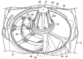
上壁部32は、遠心分離部36の底面を形成するもので、前側に向けて下方へと傾斜して形成されている。したがって、遠心分離部36は、一側すなわち図5に示す左側が上流側から下流側へと上りの傾斜に形成され、他側すなわち図5に示す右側が上流側から下流側へと下りの傾斜となるように形成されている。また、この上壁部32には、風路形成体26の外形に沿って形成された平面視円形状の円形部43が形成され、この円形部43の周囲に沿って、風路形成体26を取り付け可能なリブ44が上方に向けて突設されている。さらに、円形部43には、中央部に円形状の通気開口45が穿設されているとともに、この通気開口45の一側方に、連通開口としての開口46が穿設され、かつ、通気開口45の他側方に、集塵部37へと塵埃を導入する導入口としての集塵部導入口47が穿設されている。   The upper wall portion 32 forms the bottom surface of the centrifugal separation portion 36 and is formed to be inclined downward toward the front side. Accordingly, the centrifuge 36 is formed such that one side, that is, the left side shown in FIG. 5 has an upward slope from the upstream side to the downstream side, and the other side, that is, the right side shown in FIG. 5 has a downward slope from the upstream side to the downstream side. It is formed to become. The upper wall portion 32 is formed with a circular portion 43 having a circular shape in plan view formed along the outer shape of the air passage forming body 26, and along the circumference of the circular portion 43, the air passage forming body 26 is formed. A rib 44 that can be attached is projected upward. Further, the circular portion 43 has a circular ventilation opening 45 formed in the center thereof, and an opening 46 as a communication opening is formed on one side of the ventilation opening 45, and the ventilation opening. On the other side of 45, a dust collection portion introduction port 47 is formed as an introduction port for introducing dust into the dust collection portion 37.

通気開口45には、塵埃分離手段としての塵埃分離部51が設けられている。この塵埃分離部51は、截頭円錐状に形成された枠体52と、この枠体52の開口部52aに設けられた塵埃分離体としてのメッシュフィルタ53とを有している。そして開口部52aと通気開口45とを介して、遠心分離部36と負圧室部38とが連通されている。   The ventilation opening 45 is provided with a dust separation part 51 as dust separation means. The dust separator 51 includes a frame 52 formed in a truncated cone shape, and a mesh filter 53 as a dust separator provided in an opening 52a of the frame 52. The centrifugal separator 36 and the negative pressure chamber 38 are communicated with each other through the opening 52a and the vent opening 45.

開口46は、遠心分離部36と負圧室部38とを連通するもので、上壁部32の傾斜下端近傍、すなわち遠心分離部36の上流端部に位置している。また、この開口46は、円形部43の通気開口45の前方から通気開口45の後方一側に亘って扇形状に形成され、掃除機本体1内の一側、例えば掃除機本体1の前後方向に沿う左右方向中心線に対して図5に示す左側、換言すれば電動送風機2の吸込方向に交差する方向の一側に偏位している。さらに、この開口46には、この開口46を格子状に区画する格子リブ55が形成されているとともに、フィルタとしての塵埃分離体であるメッシュフィルタ56が設けられている。   The opening 46 communicates the centrifuge 36 and the negative pressure chamber 38, and is positioned near the inclined lower end of the upper wall 32, that is, at the upstream end of the centrifuge 36. The opening 46 is formed in a fan shape from the front side of the ventilation opening 45 of the circular portion 43 to the rear side of the ventilation opening 45, and is one side in the cleaner body 1, for example, the front-rear direction of the cleaner body 1. 5 is displaced to the left side shown in FIG. 5, in other words, to one side in the direction intersecting the suction direction of the electric blower 2. Further, the opening 46 is formed with a lattice rib 55 that partitions the opening 46 in a lattice shape, and a mesh filter 56 that is a dust separator as a filter.

集塵部導入口47は、遠心分離部36の下流側を集塵部37と連通し、上壁部32の傾斜最下端にて開口46の側方に位置し、遠心分離部36の下流端部を構成するものである。また、この集塵部導入口47は、掃除機本体1内の他側、例えば掃除機本体1の前後方向に沿う左右方向中心線に対して図5に示す右側、すなわち電動送風機2の吸込方向に交差する方向の他側に偏位している。換言すれば、この集塵部導入口47は、掃除機本体1の左右方向に対して開口46と反対側に位置している。さらに、この集塵部導入口47の後端部には、集塵部37側へと前方下部に傾斜した導入板58が延設されている。   The dust collector inlet 47 communicates with the dust collector 37 on the downstream side of the centrifugal separator 36, and is located on the side of the opening 46 at the lowermost inclined end of the upper wall portion 32. The downstream end of the centrifugal separator 36 Part. Further, the dust collection part introduction port 47 is located on the right side shown in FIG. 5 with respect to the other side in the cleaner body 1, for example, the center line in the left-right direction along the front-rear direction of the cleaner body 1, that is, the suction direction of the electric blower 2 It is deviated to the other side in the direction intersecting with. In other words, the dust collection portion introduction port 47 is located on the side opposite to the opening 46 with respect to the left-right direction of the cleaner body 1. Further, an introduction plate 58 inclined at the front lower portion is extended to the dust collection portion 37 side at the rear end portion of the dust collection portion introduction port 47.

隔壁33は、前側から後方へと若干下方に傾斜した前部壁33aと、この前部壁33aの後端部から下方へと傾斜状に連続した隔壁部としての傾斜壁33bと、この傾斜壁33bの下端部から下方に連続した下部壁33cとを備えている。   The partition wall 33 includes a front wall 33a inclined slightly downward from the front side to the rear, an inclined wall 33b as a partition wall portion continuously inclined downward from the rear end portion of the front wall 33a, and the inclined wall. A lower wall 33c continuous downward from the lower end of 33b.

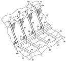
傾斜壁33bには、集塵部37の下流側を負圧室部38と連通する連通開口部としての第1集塵部開口である開口59が幅方向に多数開口形成され、これら開口59のそれぞれに塵埃分離体としての第1フィルタであるメッシュフィルタ60が設けられているとともに、これら開口59の下流側(図1および図2中の右側)には、メッシュフィルタ60の少なくとも一部を覆う阻止手段としての開閉手段である開閉体61が設けられている。   In the inclined wall 33b, a large number of openings 59 are formed in the width direction as the first dust collection part openings as communication openings that communicate the downstream side of the dust collection part 37 with the negative pressure chamber part 38. Each is provided with a mesh filter 60 as a first filter as a dust separator, and at least a part of the mesh filter 60 is covered on the downstream side of these openings 59 (the right side in FIGS. 1 and 2). An opening / closing body 61 which is an opening / closing means as a blocking means is provided.

開口59は、四角形状に形成され、各リブ62によってそれぞれ区画されている。   The opening 59 is formed in a quadrangular shape and is partitioned by each rib 62.

メッシュフィルタ60は、開口59全体の大きさよりも大きく形成されており、縁部が開口59の外方にて傾斜壁33bに接着されている。すなわち、メッシュフィルタ60には、開口59よりも外方に位置するフィルタ余剰部60aが傾斜壁33bにおける開口59の上方などに形成され、このフィルタ余剰部60aは、開口59に対向していないものの、この開口59と連通し、通気可能となっている。   The mesh filter 60 is formed larger than the entire size of the opening 59, and the edge portion is bonded to the inclined wall 33 b outside the opening 59. That is, in the mesh filter 60, a filter surplus portion 60a positioned outward from the opening 59 is formed above the opening 59 in the inclined wall 33b, and the filter surplus portion 60a is not opposed to the opening 59. The opening 59 is communicated with and can be ventilated.

また、下部壁33cの後方でかつ各開口59の下方には、筒壁部34との間の下部に集塵室開口としての第2集塵部開口である下部開口63がそれぞれ四角形状に開口形成され、細塵集塵部39の上部に連通している。すなわち、各下部開口63は、各開口59に対応してそれぞれ形成されている。このため、下部開口63は、隔壁33(傾斜壁33b、あるいは下部壁33c)と筒壁部34との間に亘って前後方向に沿って形成された各リブ64によって区画されている。さらに、これら下部開口63は、開閉体61により開閉可能となっている。   In addition, a lower opening 63, which is a second dust collection portion opening as a dust collection chamber opening, is opened in a square shape at the rear of the lower wall 33c and below each opening 59 at the lower portion between the cylindrical wall portion 34 and the opening. It is formed and communicates with the upper part of the fine dust collecting part 39. That is, each lower opening 63 is formed corresponding to each opening 59. For this reason, the lower opening 63 is partitioned by ribs 64 formed along the front-rear direction across the partition wall 33 (the inclined wall 33b or the lower wall 33c) and the cylindrical wall portion. Further, these lower openings 63 can be opened and closed by an opening / closing body 61.

そして、開閉体61は、例えば合成樹脂などの軽量の部材により各開口59および各下部開口63を覆う面積を有する板状に形成された回動体であり、下端部がリブ62,62間にて傾斜壁33bの下側の位置に回動軸61aにて軸支されて前後方向に回動可能となっている。また、これら開閉体61は、図示しない付勢手段としてのトーションばねにより上流側へ回動する方向へと付勢されている。そして、これら開閉体61は、電動送風機2の駆動時にはそれぞれトーションばねの付勢に抗して下流側へと回動して各開口59を開くとともに縁部がリブ64の上部に当接することで各下部開口63を閉じ、電動送風機2の停止時には、トーションばねの付勢によって元の状態に復帰することで傾斜壁33bに当接し、各開口59を閉じて各下部開口63を開くように構成されている。   The opening / closing body 61 is a rotating body formed in a plate shape having an area covering each opening 59 and each lower opening 63 by a lightweight member such as a synthetic resin, and the lower end portion is between the ribs 62, 62. The rotary shaft 61a is pivotally supported at a lower position of the inclined wall 33b and can be rotated in the front-rear direction. The opening / closing body 61 is urged in a direction to rotate upstream by a torsion spring as an urging means (not shown). These open / close bodies 61 are rotated downstream against the urging force of the torsion springs when the electric blower 2 is driven to open the openings 59 and the edges are in contact with the upper portions of the ribs 64. Each lower opening 63 is closed, and when the electric blower 2 is stopped, it is configured to come into contact with the inclined wall 33b by returning to its original state by the urging of the torsion spring, close each opening 59 and open each lower opening 63 Has been.

さらに、これら開閉体61は、閉じた状態で、傾斜壁33bの傾斜に沿って後方が下方へと傾斜し、その下端部が細塵集塵部39に向かっている。そして、開閉体61の少なくとも下流側面(図2中の右側面)、本実施の形態では開閉体61全体の表面には、滑りをよくするためのフッ素、帯電防止剤あるいは光触媒などがコーティングされている。なお、この開閉体61には、より軽量化するために肉抜き部などを設けてもよい。   Further, in the closed state, these open / close bodies 61 are inclined rearwardly downward along the inclination of the inclined wall 33b, and their lower end portions are directed toward the fine dust collecting portion 39. At least the downstream side surface of the opening / closing body 61 (the right side surface in FIG. 2), in this embodiment, the entire surface of the opening / closing body 61 is coated with fluorine, antistatic agent, photocatalyst, or the like to improve slippage. Yes. The opening / closing body 61 may be provided with a lightening portion or the like in order to reduce the weight.

筒壁部34は、前後方向に沿って軸方向を有する角筒状であり、後方に向けて略直線状に突出している。また、この筒壁部34の上側の外面には、プリーツフィルタ部28を集塵容器本体25に係止するための爪部34aが後方に向けて突出している。   The cylindrical wall portion 34 is a rectangular tube shape having an axial direction along the front-rear direction, and protrudes substantially linearly toward the rear. Further, a claw portion 34a for locking the pleated filter portion 28 to the dust collecting container body 25 protrudes rearward from the upper outer surface of the cylindrical wall portion 34.

排気口40は、集塵容器5を本体ケース3に取り付けた状態で、電動送風機2の吸込側に連通する円形状の吸気口65に臨むように対向する。   The exhaust port 40 faces the circular intake port 65 communicating with the suction side of the electric blower 2 in a state where the dust collecting container 5 is attached to the main body case 3.

ここで、吸気口65は、電動送風機2の前方に位置する図示しない区画壁部に穿設されて掃除機本体1の本体ケース3と集塵容器5との間に位置している。   Here, the intake port 65 is formed in a partition wall (not shown) located in front of the electric blower 2 and is located between the main body case 3 of the cleaner body 1 and the dust collecting container 5.

集塵部37は、吸込風に含まれる塵埃のうち、例えば綿ごみなどの、比較的大きい粗塵などの塵埃D1が捕集される。   The dust collection unit 37 collects dust D1 such as relatively large coarse dust such as cotton dust among the dust contained in the suction air.

一方、風路形成体26は、略円形状の吸込口66を形成する略円形状の突出管部67が前端部に位置し、この突出管部67の後端部に、平面視で右回り方向に渦巻状に形成された渦巻部68が連続して形成され、かつ、この渦巻部68の中央部に、平面視円形状の収容突出部69が形成されている。   On the other hand, in the air passage forming body 26, a substantially circular protruding tube portion 67 that forms a substantially circular suction port 66 is located at the front end portion, and the rear end portion of the protruding tube portion 67 is clockwise in a plan view. A spiral portion 68 formed in a spiral shape in the direction is continuously formed, and a receiving projection 69 having a circular shape in plan view is formed at the center of the spiral portion 68.

突出管部67は、集塵容器5を本体ケース3に取り付けた状態で接続開口13を介してホース接続口12に連通する部分である。このため、吸込口66は、掃除機本体1の左右方向の略中心に位置し、電動送風機2の駆動により空気とともに塵埃が吸い込まれる開口となっているとともに、この吸込口66の下流側近傍に、開口46が位置している。   The protruding tube portion 67 is a portion that communicates with the hose connection port 12 through the connection opening 13 in a state where the dust collecting container 5 is attached to the main body case 3. For this reason, the suction port 66 is located substantially at the center in the left-right direction of the cleaner body 1, is an opening through which dust is sucked together with air by driving the electric blower 2, and in the vicinity of the downstream side of the suction port 66. The opening 46 is located.

渦巻部68は、断面が上側に突出した円弧状であり、上流側である突出管部67側に対して、下流側の上下寸法が徐々に小さくなり、かつ、この下流側の端部が突出管部67の下部に入り込むように形成されている。したがって、渦巻部68と集塵容器本体25との間に区画され吸込口66から集塵部導入口47へ至る風路としての周回風路部Wは、下流側の断面積が上流側の断面積よりも小さくなるように、具体的には、吸込口66から集塵部導入口47へと断面積が小さくなるように構成されている。   The spiral portion 68 has an arc shape with a cross-section projecting upward, and the downstream vertical dimension gradually decreases relative to the upstream projecting tube portion 67 side, and the downstream end projects. It is formed so as to enter the lower part of the pipe part 67. Therefore, the circumferential air passage portion W, which is defined between the spiral portion 68 and the dust collecting container body 25 and extends from the suction port 66 to the dust collection portion introduction port 47, has a downstream cross-sectional area of the upstream side. Specifically, the cross-sectional area is reduced from the suction port 66 to the dust collecting portion introduction port 47 so as to be smaller than the area.

収容突出部69は、塵埃分離部51の枠体52の上端部が嵌合するように形成されている。   The housing projecting portion 69 is formed so that the upper end portion of the frame body 52 of the dust separating portion 51 is fitted.

また、底蓋27は、後端部から突出したヒンジ部70が集塵容器本体25の筒壁部34の下部に回動可能に軸支されている。そして、この底蓋27は、集塵容器5の把手部41に設けられたボタン71の操作により開くことが可能となっている。また、この底蓋27の上部には、この底蓋27を閉じた状態で集塵容器本体25の下縁部に圧接されるシール部材であるパッキン72が取り付けられている。   Further, the bottom cover 27 is pivotally supported by a hinge part 70 protruding from the rear end part so as to be rotatable at a lower part of the cylindrical wall part 34 of the dust collecting container body 25. The bottom lid 27 can be opened by operating a button 71 provided on the handle 41 of the dust collecting container 5. Further, on the upper portion of the bottom lid 27, a packing 72, which is a seal member pressed against the lower edge portion of the dust collecting container main body 25 with the bottom lid 27 closed, is attached.

さらに、プリーツフィルタ部28は、塵埃分離体としての第2フィルタであるプリーツフィルタ体73と、このプリーツフィルタ体73を保持する枠体74とを有し、排気口40を閉塞するように取り付けられる。   Further, the pleated filter section 28 includes a pleated filter body 73 that is a second filter as a dust separator and a frame body 74 that holds the pleated filter body 73, and is attached so as to close the exhaust port 40. .

プリーツフィルタ体73は、上下方向に沿うプリーツ山部とプリーツ谷部とが掃除機本体1の左右方向に交互に連続するように形成されたもので、メッシュフィルタ60よりも目が細かく形成されている。また、このプリーツフィルタ体73の後部には、このプリーツフィルタ体73よりも硬質の除塵部73aが一体的に設けられ、この除塵部73aには除塵手段75が対向して配置されている。さらに、このプリーツフィルタ体73は、上側が前方に傾斜しており、上流側面が各下部開口63の上方に位置している。   The pleat filter body 73 is formed such that pleat peaks and pleat valleys along the vertical direction are alternately continued in the left-right direction of the cleaner body 1, and has finer eyes than the mesh filter 60. Yes. Further, a dust removing portion 73a harder than the pleated filter body 73 is integrally provided at a rear portion of the pleated filter body 73, and a dust removing means 75 is disposed to face the dust removing portion 73a. Further, the pleated filter body 73 has an upper side inclined forward and an upstream side surface located above each lower opening 63.

枠体74は、プリーツフィルタ体73の周囲を囲むように形成され、外形が排気口40の内縁部に沿うように形成されている。また、この枠体74により、プリーツフィルタ体73は、上側が前方すなわち上流側へと傾斜するように保持される。このため、プリーツフィルタ体73の上流側面の下方に下部開口63を介して細塵集塵部39が位置している。また、この枠体74のプリーツフィルタ体73の下方には、前側へと細塵集塵部39に向かって下方に傾斜し微細塵D2を細塵集塵部39へと導く傾斜面76が形成されている。さらに、この枠体74の周囲には、排気口40との隙間を閉塞するためのシール部材であるパッキン77が取り付けられている。そして、枠体74の上部には、プリーツフィルタ部28を把持するためのつまみ部78が突出して設けられ、このつまみ部78には、集塵容器本体25の爪部34aが挿入係止される挿入孔78aが穿設されている。   The frame body 74 is formed so as to surround the periphery of the pleated filter body 73, and is formed so that the outer shape is along the inner edge portion of the exhaust port 40. Further, the pleated filter body 73 is held by the frame body 74 so that the upper side is inclined forward, that is, upstream. Therefore, the fine dust collecting portion 39 is located below the upstream side surface of the pleated filter body 73 via the lower opening 63. In addition, an inclined surface 76 is formed below the pleated filter body 73 of the frame body 74 so as to incline downward toward the fine dust collecting portion 39 toward the front side and guide the fine dust D2 to the fine dust collecting portion 39. Has been. Further, a packing 77 as a seal member for closing a gap with the exhaust port 40 is attached around the frame body 74. A knob part 78 for gripping the pleated filter part 28 is provided on the upper part of the frame 74 so as to protrude, and the claw part 34a of the dust collecting container body 25 is inserted and locked to the knob part 78. An insertion hole 78a is formed.

除塵手段75は、掃除機本体1の左右方向に往復移動可能な図示しない往復移動体と、この往復移動体に一体に設けられた突起79とを有し、この突起79がプリーツフィルタ体73のプリーツ山部に浅く係合し、往復移動体を左右に往復移動させることで突起79が除塵部73aに当接してプリーツ山部を乗り越えつつ移動することにより、プリーツフィルタ体73に振動を与えてプリーツフィルタ体73に付着した塵埃である微細塵D2を、各下部開口63を介して細塵集塵部39へと落下させるように構成されている。   The dust removing means 75 has a reciprocating body (not shown) that can reciprocate in the left-right direction of the cleaner body 1 and a protrusion 79 provided integrally with the reciprocating body. By engaging the pleat peak shallowly and reciprocating the reciprocating moving body to the left and right, the projection 79 abuts against the dust removing part 73a and moves over the pleat peak, thereby giving vibration to the pleated filter body 73. Fine dust D2, which is dust adhering to the pleated filter body 73, is configured to drop onto the fine dust collecting portion 39 through each lower opening 63.

なお、往復移動体は、例えば電動送風機2の駆動を停止させた時、あるいは電動送風機2を起動させた時など、任意の所定のタイミングで所定時間往復移動されるように制御される。   The reciprocating body is controlled to reciprocate for a predetermined time at an arbitrary predetermined timing, for example, when driving of the electric blower 2 is stopped or when the electric blower 2 is started.

次に、上記一実施の形態の動作を説明する。   Next, the operation of the above embodiment will be described.

まず、蓋体4を上方に回動させて開け、風路形成体26およびプリーツフィルタ部28を取り付けた集塵容器5を載置部8に載置した状態で、蓋体4を下方に回動させ、この蓋体4と載置部8との間に集塵容器5を挟持する。   First, the lid body 4 is rotated upward to be opened, and the lid body 4 is rotated downward with the dust collecting container 5 to which the air path forming body 26 and the pleated filter section 28 are mounted placed on the placement section 8. The dust collecting container 5 is sandwiched between the lid 4 and the mounting portion 8.

このとき、集塵容器5の吸込口66が、蓋体4の管部11の接続開口13に気密に接続され、かつ、集塵容器5の排気口40およびこの排気口40に取り付けられたプリーツフィルタ部28が、電動送風機2の吸気口65に対向する。   At this time, the suction port 66 of the dust collecting container 5 is hermetically connected to the connection opening 13 of the tube portion 11 of the lid 4, and the exhaust port 40 of the dust collecting container 5 and the pleats attached to the exhaust port 40. The filter unit 28 faces the intake port 65 of the electric blower 2.

次いで、ホース接続口12に、集塵ホース15、延長管21および吸込口体22を順次連通接続するとともに、本体ケース3から図示しない電源コードを導出して、商用交流電源に接続し、把持部17を把持した状態で所望の操作スイッチ18を操作して、電動送風機2を所望の動作モードで駆動させる。   Next, the dust collecting hose 15, the extension pipe 21 and the suction port body 22 are sequentially connected to the hose connection port 12, and a power cord (not shown) is led out from the main body case 3 and connected to a commercial AC power source. The desired operation switch 18 is operated in a state where 17 is held, and the electric blower 2 is driven in a desired operation mode.

この駆動により生じる吸込風によって各開閉体61が回動軸61aを中心として図1に示すようにトーションばねの付勢に抗して後方へと回動し、各開口59が開くとともに、これら開閉体61がリブ64に接触することで各下部開口63を閉じ細塵集塵部39を密閉することで、この細塵集塵部39内に捕集された微細塵が下部開口63から負圧室部38へと負圧により吸い上げられることを防止する。このとき、開閉体61が各リブ64に当接した衝撃により、各開閉体61の下流側面などに付着していた塵埃などが細塵集塵部39内へと振り落とされる。   As shown in FIG. 1, the opening / closing bodies 61 are rotated by the suction air generated by the driving to the rear against the urging force of the torsion spring as shown in FIG. When the body 61 contacts the rib 64, each lower opening 63 is closed and the fine dust collecting part 39 is sealed, so that the fine dust collected in the fine dust collecting part 39 is negatively pressured from the lower opening 63. The suction to the chamber 38 due to negative pressure is prevented. At this time, due to the impact of the opening / closing bodies 61 in contact with the ribs 64, dust or the like adhering to the downstream side surface of each opening / closing body 61 is shaken off into the fine dust collecting portion 39.

この状態で、作業者は吸込口体22を床面上に接地して前後に走行させて、先端側から床面上の塵埃を空気とともに吸い込む。   In this state, the operator touches the suction port body 22 on the floor surface and travels forward and backward, and sucks dust on the floor surface together with air from the front end side.

吸い込まれた空気は吸込風となり、吸込口体22、延長管21、集塵ホース15、ホース接続口12および接続開口13を経由して、集塵容器5の吸込口66から遠心分離部36へと吸い込まれる。   The sucked air becomes a suction air and passes from the suction port 66 of the dust collecting container 5 to the centrifugal separator 36 via the suction port body 22, the extension pipe 21, the dust collection hose 15, the hose connection port 12 and the connection opening 13. And sucked.

この吸込風は、大部分の塵埃とともに塵埃分離部51の周囲に旋回する旋回風と、吸込口26から円形部43の開口46(メッシュフィルタ56)を介して後方へと直線状に進む、すなわち直進する直進風とに分離される。   This suction air travels linearly from the suction port 26 to the rear through the opening 46 (mesh filter 56) of the circular portion 43, that is, the swirling air swirling around the dust separating portion 51 together with most dust, that is, It is separated into a straight wind that goes straight.

このとき、旋回風は、一部が開口部52aを通過して負圧室部38へと流入し、この通過の際にメッシュフィルタ53により塵埃を捕集されるとともに、さらに残りの部分は、上壁部32に沿って大部分の塵埃とともに集塵部導入口47から集塵部37内へと吸い込まれる。   At this time, a part of the swirling wind passes through the opening 52a and flows into the negative pressure chamber 38, and dust is collected by the mesh filter 53 during this passage, and the remaining part is Along with the upper wall portion 32, most of the dust is sucked into the dust collecting portion 37 from the dust collecting portion introduction port 47.

この集塵部37へ流入した旋回風に含まれる塵埃のうち、比較的大きい粗塵は、そのまま集塵部37内へと落下して捕集され、比較的小さい細塵は、旋回風が各開口59を通過して負圧室部38へと流入する際にメッシュフィルタ60により捕集される。このように、集塵部37に塵埃D1が捕集される。   Of the dust contained in the swirling wind that has flowed into the dust collecting portion 37, relatively large coarse dust falls into the dust collecting portion 37 and is collected as it is. When the fluid passes through the opening 59 and flows into the negative pressure chamber 38, it is collected by the mesh filter 60. In this way, the dust D1 is collected in the dust collecting portion 37.

一方、直進風には、殆ど塵埃が含まれていないものの、わずかに含まれる塵埃が負圧室部38を経由してプリーツフィルタ部28のプリーツフィルタ体73を通過し、この通過の際に、このプリーツフィルタ体73に、メッシュフィルタ56により捕集されなかった微細塵が捕集される。   On the other hand, the straight wind hardly contains dust, but slightly contained dust passes through the pleated filter body 73 of the pleated filter part 28 via the negative pressure chamber part 38, and at the time of this passage, Fine dust that has not been collected by the mesh filter 56 is collected in the pleated filter body 73.

プリーツフィルタ体73を通過した旋回風と直進風とは、ともに排気口40から集塵容器5の外部へと排気された後、吸気口65から電動送風機2へと吸い込まれ、この電動送風機2を通過して排気風となり、本体ケース3に穿設された図示しない排気孔を介して掃除機本体1の外部へと排気される。   Both the swirling wind and the straight wind that have passed through the pleated filter body 73 are exhausted from the exhaust port 40 to the outside of the dust collecting container 5 and then sucked into the electric blower 2 from the intake port 65. It passes through and becomes exhaust air, and is exhausted to the outside of the cleaner main body 1 through an exhaust hole (not shown) formed in the main body case 3.

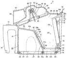
掃除が終了し、作業者が操作スイッチ18を操作して電動送風機2の駆動を停止させて吸込風が停止すると、図2に示すように、各開閉体61が回動軸61aを中心としてトーションばねの付勢により前方へと回動し、各開口59を覆って閉じることで、各下部開口63が開く。   When the cleaning is completed and the operator operates the operation switch 18 to stop the driving of the electric blower 2 and the suction air is stopped, each opening / closing body 61 is torsioned around the rotation shaft 61a as shown in FIG. Each lower opening 63 is opened by rotating forward by the bias of the spring and covering and closing each opening 59.

この状態で、除塵手段75が駆動され、突起79が左右方向に往復移動することで、この突起79がプリーツフィルタ体73に付着した微細塵をこのプリーツフィルタ体73から下部開口63を介して細塵集塵部39へと落下させる。   In this state, the dust removing means 75 is driven, and the projection 79 reciprocates in the left-right direction, so that the fine dust adhered to the pleated filter body 73 by the projection 79 is reduced from the pleated filter body 73 through the lower opening 63. Drop to the dust collector 39.

このとき、微細塵がメッシュフィルタ60を下流側から上流側すなわち集塵部37側へと通過することを開閉体61が防止するとともに、この開閉体61の下流側面へと落下した微細塵は、この開閉体61の傾斜に沿って下部開口63を介して細塵集塵部39へと導かれ、この細塵集塵部39に捕集される。   At this time, the opening / closing body 61 prevents the fine dust from passing through the mesh filter 60 from the downstream side to the upstream side, i.e., the dust collecting portion 37 side, and the fine dust dropped to the downstream side surface of the opening / closing body 61 is Along the inclination of the opening / closing body 61, the fine dust collection unit 39 is guided through the lower opening 63 and collected by the fine dust collection unit 39.

この後、作業者は、蓋体4を上方へ回動させて開き、集塵容器5を本体ケース3から取り外した後、例えばごみ箱などの上でボタン71を押すことで底蓋27を開き、廃棄開口42から、集塵部37内の塵埃D1および細塵集塵部39内の微細塵D2を廃棄する。   Thereafter, the operator opens the lid 4 by rotating the lid 4 upward, removes the dust collecting container 5 from the main body case 3, and then opens the bottom lid 27 by pressing the button 71 on a trash can, for example. From the disposal opening 42, the dust D1 in the dust collector 37 and the fine dust D2 in the fine dust collector 39 are discarded.

また、風路形成体26を集塵容器本体25から取り外し、各メッシュフィルタ53,56などを掃除する。   Further, the air passage forming body 26 is removed from the dust collecting container body 25, and the mesh filters 53, 56 and the like are cleaned.

さらに、プリーツフィルタ部28を集塵容器本体25から取り外し、メッシュフィルタ60を掃除したり、プリーツフィルタ体73から除去された微細塵D2のうち集塵容器本体25に付着しているものを掃除したりする。   Further, the pleat filter unit 28 is removed from the dust collection container body 25, and the mesh filter 60 is cleaned, or the fine dust D2 removed from the pleat filter body 73 is cleaned of what is attached to the dust collection container body 25. Or

そして、風路形成体26および底蓋27を元の状態に戻した後、集塵容器5を再度本体ケース3に取り付けて使用する。   And after returning the air path formation body 26 and the bottom cover 27 to the original state, the dust container 5 is attached to the main body case 3 again and used.

上述したように、上記一実施の形態によれば、除塵手段75によりプリーツフィルタ体73から除去した微細塵D2のメッシュフィルタ60側への移動を、このメッシュフィルタ60を覆う開閉体61によって阻止することで、このプリーツフィルタ体73から一旦除去した微細塵D2が電動送風機2の駆動によりメッシュフィルタ60を再度通過してプリーツフィルタ体73へ再付着することを防止できる。   As described above, according to the above embodiment, the opening / closing body 61 covering the mesh filter 60 prevents the fine dust D2 removed from the pleated filter body 73 by the dust removing means 75 from moving toward the mesh filter 60 side. Thus, it is possible to prevent the fine dust D2 once removed from the pleated filter body 73 from passing through the mesh filter 60 again by driving the electric blower 2 and reattaching to the pleated filter body 73.

具体的に、開閉体61は、電動送風機2の吸込風によってメッシュフィルタ60の下流側を開放し、電動送風機2の停止に伴う吸込風の停止によってメッシュフィルタ60の下流側を覆うように開閉動作するため、メッシュフィルタ60を取り付ける各開口59の開口面積に拘らず、プリーツフィルタ体73から除去した微細塵D2がメッシュフィルタ60を下流側から上流側に通過することがないから、各開口59の開口面積を比較的広く取ることが可能となり、吸込性能を確保することができる。   Specifically, the opening / closing body 61 opens and closes the downstream side of the mesh filter 60 by the suction air of the electric blower 2 and covers the downstream side of the mesh filter 60 by the stop of the suction air accompanying the stop of the electric blower 2. Therefore, regardless of the opening area of each opening 59 to which the mesh filter 60 is attached, the fine dust D2 removed from the pleated filter body 73 does not pass through the mesh filter 60 from the downstream side to the upstream side. The opening area can be made relatively large, and the suction performance can be ensured.

さらに、開閉体61は、メッシュフィルタ60の下流側の開閉に逆に対応して細塵集塵部39の下部開口63を開閉するため、この細塵集塵部39に捕集された微細塵D2が、電動送風機2の駆動時(メッシュフィルタ60(開口59)の開放時)に負圧によって吸い上げられてプリーツフィルタ体73に再付着することなども、確実に防止できる。   Further, the open / close body 61 opens and closes the lower opening 63 of the fine dust collecting portion 39 in response to the opening and closing of the downstream side of the mesh filter 60, so that the fine dust collected by the fine dust collecting portion 39 is opened. It is possible to reliably prevent D2 from being sucked up by negative pressure and reattaching to the pleated filter body 73 when the electric blower 2 is driven (when the mesh filter 60 (opening 59) is opened).

しかも、同一の開閉体61によってメッシュフィルタ60の下流側の開閉と逆に対応して下部開口63を開閉させる機構とすることにより、これら手段を別個に設ける場合と比較して、構成を簡略化できる。   In addition, by using a mechanism that opens and closes the lower opening 63 corresponding to the opening and closing of the downstream side of the mesh filter 60 by the same opening and closing body 61, the configuration is simplified compared to the case where these means are provided separately. it can.

具体的に、開閉体61は、メッシュフィルタ60の下方に位置する下部開口63の上方に下端部が回動可能に軸支されこの下部開口63を覆う回動体とすることで、阻止手段と開閉手段とを兼用する構成を容易に形成できる。   Specifically, the opening / closing body 61 is formed as a rotating body whose lower end is pivotally supported above the lower opening 63 positioned below the mesh filter 60 so as to cover the lower opening 63, thereby opening and closing the blocking means. A configuration that also serves as the means can be easily formed.

さらに、プリーツフィルタ体73は、上側が前方へと傾斜して下部開口63の上方に臨んでいるため、除塵手段75によってプリーツフィルタ体73から除去した微細塵D2をほぼ確実に下部開口63へと導くことができる。   Furthermore, since the pleated filter body 73 is inclined upward to the front and faces the lower opening 63, the fine dust D2 removed from the pleated filter body 73 by the dust removing means 75 is almost certainly transferred to the lower opening 63. Can lead.

また、メッシュフィルタ60は、傾斜壁33bに設けることにより、上側が前方へと傾斜するので、吸込風によってメッシュフィルタ60の上流面側に押し付けられた綿ごみなどの塵埃D1が集塵部37内に落下しやすくなり、メッシュフィルタ60の目詰まりなどが防止される。   In addition, since the mesh filter 60 is provided on the inclined wall 33b, the upper side is inclined forward, so that dust D1 such as cotton dust pressed against the upstream surface side of the mesh filter 60 by the suction air is collected in the dust collecting portion 37. The mesh filter 60 can be prevented from being clogged.

さらに、メッシュフィルタ60は、各開口59に対向する部分が次第に目詰まりしてきても、フィルタ余剰部60aから空気が抜けることで、このフィルタ余剰部60aにて塵埃を捕集し、メッシュフィルタ60をメンテナンスすることなく連続使用可能な時間を延ばすことができる。   Further, the mesh filter 60 collects dust in the filter surplus portion 60a when air is released from the filter surplus portion 60a even if the portions facing the openings 59 are gradually clogged. The time for continuous use can be extended without maintenance.

そして、開閉体61は、少なくとも下流側面に、滑りをよくするためのコーティングを施しているので、プリーツフィルタ体73から除去した微細塵D2などがこの開閉体61に付着しにくくなる。   Since the opening / closing body 61 is coated on at least the downstream side surface to improve the slip, the fine dust D2 removed from the pleated filter body 73 is less likely to adhere to the opening / closing body 61.

なお、上記一実施の形態において、プリーツフィルタ体73から除塵手段75により除去した微細塵D2は、細塵集塵部39に捕集せずに、風路内などに捕集してもよい。   In the above-described embodiment, the fine dust D2 removed from the pleated filter body 73 by the dust removing means 75 may be collected in the air passage or the like without being collected in the fine dust collecting portion 39.

また、開口59および下部開口63は、それぞれ複数ずつ設けたが、それぞれ1つずつなどでもよい。この場合には、開閉体61も対応して1つずつなどとする。   Further, although a plurality of openings 59 and a plurality of lower openings 63 are provided, one each may be provided. In this case, the opening / closing bodies 61 are also provided one by one.

さらに、開閉体61によるメッシュフィルタ60の下流側の開閉と逆に対応して下部開口63を開閉する開閉手段を、開閉体61と別個に設けてもよい。   Furthermore, an opening / closing means for opening / closing the lower opening 63 corresponding to the opening / closing of the mesh filter 60 downstream by the opening / closing body 61 may be provided separately from the opening / closing body 61.

そして、阻止手段は、例えば開閉体61に代えて、メッシュフィルタ60の上方にひさし状の部材を固定するなど、メッシュフィルタ60側への微細塵D2の移動を阻止できれば、任意の構成とすることが可能である。   The blocking means may be of any configuration as long as it can block the movement of fine dust D2 toward the mesh filter 60, for example, by fixing an eaves-like member above the mesh filter 60 instead of the opening / closing body 61. Is possible.

また、集塵容器5は、サイクロン分離以外の任意の塵埃分離方法を用いるものでよい。   The dust collecting container 5 may use any dust separation method other than the cyclone separation.

さらに、電気掃除機は、集塵容器5を備えたものだけでなく、第1フィルタの下流側に第2フィルタを配置し、この第2フィルタに捕集した塵埃を除去する除塵手段を備えたものであれば、対応して用いることができる。   Furthermore, the vacuum cleaner is not only provided with the dust collection container 5, but also provided with a dust removing means for disposing the second filter on the downstream side of the first filter and removing the dust collected by the second filter. If it is a thing, it can be used correspondingly.

そして、上記構成は、アップライト型、ハンディ型、あるいは自律走行型などの各種電気掃除機にも対応して用いることができる。   And the said structure can be used corresponding to various vacuum cleaners, such as an upright type, a handy type, or an autonomous running type.

本発明の一実施の形態の電気掃除機の電動送風機の駆動状態での要部を示す縦断面図である。It is a longitudinal cross-sectional view which shows the principal part in the drive state of the electric blower of the vacuum cleaner of one embodiment of this invention. 同上電気掃除機の電動送風機の停止時状態での要部を示す縦断面図である。It is a longitudinal cross-sectional view which shows the principal part in the state at the time of the stop of the electric blower of a vacuum cleaner same as the above. 同上電気掃除機の要部を後方から示す斜視図である。It is a perspective view which shows the principal part of a vacuum cleaner same as the above from back. 同上電気掃除機の集塵部の一部を示す平面図である。It is a top view which shows a part of dust collection part of a vacuum cleaner same as the above. 同上電気掃除機の集塵部の一部を前方から示す斜視図である。It is a perspective view which shows a part of dust collection part of a vacuum cleaner same as the above from the front. 同上電気掃除機の掃除機本体を示す斜視図である。It is a perspective view which shows the vacuum cleaner main body of a vacuum cleaner same as the above. 同上電気掃除機を示す斜視図である。It is a perspective view which shows a vacuum cleaner same as the above.

符号の説明Explanation of symbols

1 掃除機本体
2 電動送風機
39 集塵室としての細塵集塵部
60 第1フィルタであるメッシュフィルタ
61 阻止手段としての開閉手段である開閉体
63 集塵室開口としての下部開口
73 第2フィルタであるプリーツフィルタ体
75 除塵手段
1 Vacuum cleaner body 2 Electric blower
39 Fine dust collection part as a dust collection chamber
60 Mesh filter as the first filter
61 Opening / closing body as opening / closing means as blocking means
63 Lower opening as dust collection chamber opening
73 Pleated filter body as second filter
75 Dust removal means

Claims (5)

電動送風機を収容した掃除機本体と、
この掃除機本体の前記電動送風機の吸込側に位置して設けられた第1フィルタと、
前記掃除機本体の前記電動送風機の吸込側でかつ前記第1フィルタよりも下流側に位置して設けられ、この第1フィルタよりも目が細かい第2フィルタと、
この第2フィルタに捕集した塵埃を除去する除塵手段と、
この除塵手段により前記第2フィルタから除去した塵埃の前記第1フィルタ側への移動を阻止する阻止手段と
を具備したことを特徴とした電気掃除機。
A vacuum cleaner body containing an electric blower,
A first filter provided on the suction side of the electric blower of the cleaner body;
A second filter that is provided on the suction side of the electric blower of the cleaner body and on the downstream side of the first filter; the second filter is finer than the first filter;
Dust removing means for removing dust collected in the second filter;
An electric vacuum cleaner comprising: blocking means for blocking movement of dust removed from the second filter by the dust removing means toward the first filter.
阻止手段は、電動送風機の吸込風によって第1フィルタの下流側の少なくとも一部を開放し、前記吸込風の停止によって前記第1フィルタの下流側の少なくとも一部を覆うように動作する
ことを特徴とした請求項1記載の電気掃除機。
The blocking means operates so as to open at least part of the downstream side of the first filter by the suction air of the electric blower and cover at least part of the downstream side of the first filter by stopping the suction air. The vacuum cleaner according to claim 1.
阻止手段は、第1フィルタの下流側の少なくとも一部を開閉可能であり、
除塵手段により第2フィルタから除去した塵埃が通過する集塵室開口を備え、この集塵室開口を通過した塵埃を捕集する集塵室と、
前記阻止手段の開閉と反対に対応して前記集塵室開口を開閉する開閉手段とを具備した
ことを特徴とした請求項2記載の電気掃除機。
The blocking means can open and close at least a part of the downstream side of the first filter,
A dust collection chamber having a dust collection chamber opening through which dust removed from the second filter by the dust removing means passes, and collecting the dust that has passed through the dust collection chamber opening;
The vacuum cleaner according to claim 2, further comprising opening / closing means for opening / closing the dust collection chamber opening corresponding to the opening / closing of the blocking means.
開閉手段は、阻止手段と同一の部材である
ことを特徴とした請求項3記載の電気掃除機。
The vacuum cleaner according to claim 3, wherein the opening / closing means is the same member as the blocking means.
集塵室開口は、第1フィルタの下方に位置し、
阻止手段は、下端部が前記集塵室開口の上方にて回動可能に軸支されこの集塵室開口を覆う回動体である
ことを特徴とした請求項4記載の電気掃除機。
The dust collection chamber opening is located below the first filter,
5. The electric vacuum cleaner according to claim 4, wherein the blocking means is a rotating body whose lower end is pivotally supported so as to be rotatable above the dust collection chamber opening and covers the dust collection chamber opening.
JP2008044507A 2008-02-26 2008-02-26 Vacuum cleaner Pending JP2009201568A (en)

Priority Applications (1)

Application Number Priority Date Filing Date Title
JP2008044507A JP2009201568A (en) 2008-02-26 2008-02-26 Vacuum cleaner

Applications Claiming Priority (1)

Application Number Priority Date Filing Date Title
JP2008044507A JP2009201568A (en) 2008-02-26 2008-02-26 Vacuum cleaner

Publications (1)

Publication Number Publication Date
JP2009201568A true JP2009201568A (en) 2009-09-10

Family

ID=41144430

Family Applications (1)

Application Number Title Priority Date Filing Date
JP2008044507A Pending JP2009201568A (en) 2008-02-26 2008-02-26 Vacuum cleaner

Country Status (1)

Country Link
JP (1) JP2009201568A (en)

Cited By (3)

* Cited by examiner, † Cited by third party
Publication number Priority date Publication date Assignee Title
JP2010269122A (en) * 2009-04-20 2010-12-02 Hitachi Appliances Inc Vacuum cleaner
JP2016146998A (en) * 2015-02-13 2016-08-18 三菱電機株式会社 Cyclone separator and vacuum cleaner
JP2017060892A (en) * 2017-01-12 2017-03-30 三菱電機株式会社 Cyclone separator and vacuum cleaner

Citations (4)

* Cited by examiner, † Cited by third party
Publication number Priority date Publication date Assignee Title
JPS5739551U (en) * 1980-08-20 1982-03-03
JPS57180931A (en) * 1982-04-13 1982-11-08 Matsushita Electric Ind Co Ltd Electric cleaner
JPS57202852U (en) * 1981-06-18 1982-12-24
JPS6261659U (en) * 1985-10-08 1987-04-16

Patent Citations (4)

* Cited by examiner, † Cited by third party
Publication number Priority date Publication date Assignee Title
JPS5739551U (en) * 1980-08-20 1982-03-03
JPS57202852U (en) * 1981-06-18 1982-12-24
JPS57180931A (en) * 1982-04-13 1982-11-08 Matsushita Electric Ind Co Ltd Electric cleaner
JPS6261659U (en) * 1985-10-08 1987-04-16

Cited By (3)

* Cited by examiner, † Cited by third party
Publication number Priority date Publication date Assignee Title
JP2010269122A (en) * 2009-04-20 2010-12-02 Hitachi Appliances Inc Vacuum cleaner
JP2016146998A (en) * 2015-02-13 2016-08-18 三菱電機株式会社 Cyclone separator and vacuum cleaner
JP2017060892A (en) * 2017-01-12 2017-03-30 三菱電機株式会社 Cyclone separator and vacuum cleaner

Similar Documents

Publication Publication Date Title
US7682414B2 (en) Dust collecting unit for use in cleaner
RU2453261C1 (en) Electric vacuum cleaner
EP1974642B1 (en) Electric vacuum cleaner
JP4342526B2 (en) Electric vacuum cleaner
EP1554965A1 (en) Electric cleaner
JP4738064B2 (en) Vacuum cleaner
JP4901569B2 (en) Dust collector and vacuum cleaner
JP2009201568A (en) Vacuum cleaner
JP4011079B2 (en) Electric vacuum cleaner
JP4271204B2 (en) Electric vacuum cleaner
JP5911230B2 (en) Electric vacuum cleaner
JP2005131135A (en) Vacuum cleaner
JP5388717B2 (en) Dust collector and vacuum cleaner
JP2008142255A (en) Dust collector and vacuum cleaner
KR101282536B1 (en) Dust collecting apparatus and electric cleaner
JP5086859B2 (en) Electric vacuum cleaner
JP4738063B2 (en) Vacuum cleaner
JP4783207B2 (en) Vacuum cleaner dust collector
JP5715903B2 (en) Electric vacuum cleaner
JP2010022575A (en) Vacuum cleaner
JP2006346099A (en) Electric cleaner and its dust collecting device
JP4982175B2 (en) Dust collector and vacuum cleaner
JP5818558B2 (en) Electric vacuum cleaner
JP5801131B2 (en) Electric vacuum cleaner
JP5258421B2 (en) Electric vacuum cleaner

Legal Events

Date Code Title Description
A621 Written request for application examination

Free format text: JAPANESE INTERMEDIATE CODE: A621

Effective date: 20110117

A977 Report on retrieval

Free format text: JAPANESE INTERMEDIATE CODE: A971007

Effective date: 20120802

A131 Notification of reasons for refusal

Free format text: JAPANESE INTERMEDIATE CODE: A131

Effective date: 20120815

A02 Decision of refusal

Effective date: 20121205

Free format text: JAPANESE INTERMEDIATE CODE: A02