EP2305083B1 - Einhändig betätigte vertikale mühle für feste aromastoffe - Google Patents
Einhändig betätigte vertikale mühle für feste aromastoffe Download PDFInfo
- Publication number
- EP2305083B1 EP2305083B1 EP09771932.2A EP09771932A EP2305083B1 EP 2305083 B1 EP2305083 B1 EP 2305083B1 EP 09771932 A EP09771932 A EP 09771932A EP 2305083 B1 EP2305083 B1 EP 2305083B1
- Authority
- EP
- European Patent Office
- Prior art keywords
- sector
- shell
- unit
- handle
- slot
- Prior art date
- Legal status (The legal status is an assumption and is not a legal conclusion. Google has not performed a legal analysis and makes no representation as to the accuracy of the status listed.)
- Not-in-force
Links
Images





Classifications
-
- A—HUMAN NECESSITIES
- A47—FURNITURE; DOMESTIC ARTICLES OR APPLIANCES; COFFEE MILLS; SPICE MILLS; SUCTION CLEANERS IN GENERAL
- A47J—KITCHEN EQUIPMENT; COFFEE MILLS; SPICE MILLS; APPARATUS FOR MAKING BEVERAGES
- A47J42/00—Coffee mills; Spice mills
- A47J42/32—Coffee mills; Spice mills with other grinding or pulverising members
- A47J42/34—Coffee mills; Spice mills with other grinding or pulverising members hand driven
Definitions
- This application relates to a kitchen appliance. To be exact, it is a single-handed vertical solid material grinder.
- a traditional grinder must be operated using both hands, such as the Chinese utility patent ZL01207465.9 .
- this grinder includes an upper binding unit and a lower binding unit.
- Each binding unit has a tooth ring with screw threads.
- the user need to use both hands to rotate both upper and lower binding units.
- the particles are grinded between the teeth of the two tooth rings. It is not convenient to use both hands to operated one machine in a busy kitchen environment.
- a spice crusher comprising a main body a handle pivotally mounted on said main body, a large gear and a crushing plate with serrations and a fineness control mechanism is disclosed.
- Said handle moves around a pin which provides the mounting of the handle to the main body.
- the spice to be crushed is inserted to an inner chamber of the main body from an inlet covered by a lid and the crushed spice is collected from a passage provided on the main body.
- the gear and the plate operates together in order to crush the spice.
- a driving gear is mounted to the handle in order to transfer the movement of the handle to the large gear and a pinion is provided on the large gear in connection with the driving gear.
- the handle is moved around the pin and the spice provided in the inner chamber passes between the large gear and the crushing plate.
- the spice is crushed and the crushed spice is taken from the passage. Therefore, the spice is easily crushed by using only one hand.
- a peppercorn crusher which comprises a main body, a handle pivotally mounted on said main body, a cylindrical pin which provides the mounting of the handle to the main body, an inner chamber in which the spice to be crushed is inserted from an inlet covered by a top cover, a passage from which the crushed spice is collected and which is provided on the main body, a big gear, a crushing plate with serrations and a fineness control mechanism, a sector gear which is mounted to the handle in order to transfer the movement of the handle to the large gear, a pinion which is provided on the big gear in connection with the sector gear and a spring bow which pushes the handle away from the body is disclosed.
- the peppercorn crusher also provides crushing of spices by using only one hand.
- a mill for crushing the table salt comprises a bottomless box with a lid having an extension in which a notch provided into which the salt is placed, a crushing cylinder housed in the box, a board for crushing the salt with cylinder, a lever which is able to move back and forth and which is fixed to the cylinder in order to provide the rolling of the cylinder, a spring which pushes back the lever into previous position and a screw which tightens or loosens the board in order to obtain the desired size of the salt.
- salt is filled into the box and the lever is moved back and forth by means of two fingers one of which is inserted in the notch.
- the crushing cylinder rolls and salt is crushed between the cylinder and the board due to the rolling of the cylinder.
- a mill for crushing the table salt comprises a cylindrical body into which the crushed salt is filled, a crusher cylinder which provided in the body, which can pivot around a pin and on the periphery of which is provided with a series of grooves, a lever which is in connection with the crusher cylinder, which is able to move back and forth in order to pivot the cylinder and which is provided with two rounded notches, a plate on which there is provided a series of grooves, a spring which pushes the lever (8) into previous position and a screw) which allows obtaining the degree of fineness of ground salt.
- salt is filled in the body and the lever is pivoted such that the lever moves back and forth. By pivoting of the lever, the crushing cylinder also pivots around the pin and the salt passing between the cylinder and the plate is crushed.
- the technical issue that the present invention aims to solve is: to overcome the current grinder's inconvenience of requiring two hands to operate, to provide a vertical solid material grinder that only requires one hand to use, thus to reduce the effort of operation.
- the technical solution to the technical issue of the present invention is: to provide a single-handed vertical solid material grinder, which includes: a shell that has a material inlet and an outlet, which has a material chamber that contains the solid material particles and is connected to the inlet, a handle set with a motion handle and a mounted handle.
- the upper part of the motion handle and the mounted handle stretches outside the shell.
- the lower part of the mounted handle is mounted inside the shell.
- the lower part of the motion handle has a driving axis that is mounted inside the shell. The said motion handle can move back and forth around the said driving axis.
- a grinding set that includes a sector unit with a sector surface inside the shell and a grinding unit that is placed outside the sector surface.
- Between the motion handle and the sector unit is a driving set that will driving the sector unit move back and forth around the spinning axis.
- the said driving set includes shaft and slot set between the said sector unit and the lower part of the motion handle.
- the said sector unit's spinning axis and the motion handle's driving axis overlap each other.
- the said sector unit fits into the motion handle via the driving set.
- the single-handed vertical solid material grinder there is a horizontal slot at the outlet in the shell.
- the slot has a slotting cover that can cover the outlet.
- the said slotting cover has a vertical trail.
- the single-handed vertical solid material grinder there is a notch on the inner surface of the shell.
- a notch cover on the notch.
- Between the notch cover and the notch is a slot.
- There is a sector slot in the said notch cover that has the same rotation axis as the sector unit. The said driving shaft passes through the said sector slot and matches into the vertical slot of the slotting cover.
- the particle removing column In the single-handed vertical solid material grinder, there is a particle removing column inside the shell under the said sector unit.
- the particle removing column has a particle removing surface that faces the sector surface and has the same center as the sector surface.
- the said particle removing surface is right outside the sector surface.
- the said elastic repositioning unit is a spring between the sector surface and the shell.
- the said grinding unit is placed in the grinding unit chamber inside the shell and facing the sector surface. There is a distance adjustment screw on the grinding unit in the shell to adjust the distance between the fixed teeth and the parallel teeth.
- the said shell has an outer shell and an inner shell.
- the said material chamber is between the outer shell and the inner shell.
- Both the said inlet and outlet are on the said outer shell.
- the said aperture connecting the material chamber and the grinding unit is in the inner shell.
- the said handle set and the grinding set are inside the inner shell.
- sealing cover on the inlet.
- the said sealing cover has a mounting axis on one end, which is mounted to the outer shell. To the other end is a stretching rim that covers the inlet.
- the single-handed vertical solid material grinder there is a teeth unit on the sector surface of the sector unit.
- the said parallel teeth are all located on the outside of the teeth unit.
- the single-handed vertical solid material grinder there is a collection box under the outlet on the outer shell to collect the particles generated.
- the single-handed vertical solid material grinder has these benefits:
- the handle set with the motion handle and the mounted handle and the grinding unit with the sector unit with a sector surface and a grinding unit are both placed inside the shell. Both the sector unit and the grinding unit are in the shell.
- the sector unit can spin along the spinning axis inside the shell.
- the motion handle can spin along the driving axis inside the shell.
- the grinding unit is mounted in the shell and has at least one fixed teeth that matches into the sector surface's teeth.
- the teeth on the sector surface will sweep over the fixed teeth of the grinding unit, bring the particles that falls into the fixed teeth from the material chamber through the aperture to move with the teeth, smash the particles with the teeth on the sector unit and the fixed teeth on the grinding unit, and achieve the grinding effect.
- the motion handle since there is a elastic repositioning unit between the motion handle and the shell, when the user looses the hand on the handle set, the motion handle will be pushed away from the mounted handle by the elastic repositioning unit, thus pushing the teeth on the sector surface back. The grinding unit is then move back to initial position.
- the teeth on the sector surface of the grinding set will move back and forth along the spinning axis.
- the teeth on the sector unit keep on smashing the particles with the fixed teeth on the grinding unit to smaller ones.
- the user can continuously keep on grinding by using only one hand.
- the other hand can take care of other business. It is much more convenient.
- a slot is set at the outlet in the shell.
- the driving shaft on the side of the sector surface will drive the slot cover to move along the slot, thus open the outlet so that the finished particles can slide out through the outlet.
- the driving shaft will driving the slot cover slide back to cover the outlet to prevent outside dust or other dirt from entering the shell when the grinder is not in use.
- the collection box under the outlet at the bottom of the outer shell for colleting the finished particles.
- the finished particles will be collected into the collection box. After all the particles are grinded, the collection box can be taken out and the particles inside can be retrieved, thus preventing the finished particles from leaking and splashing around during the grinding process.
- the particle removing column has a particle removing surface that faces the sector surface and has the same center as the sector surface.
- the said particle removing surface is very close to the outside of the sector surface so that the sector surface and the particle removing surface are parallel to each other and have a very small distance.
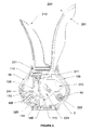
- this implementation of this single-handed vertical solid material grinder of this utility patent includes shell (100), handle set (200), and grinding set (not shown in Figure-1).
- Shell (100) consists of inner shell (110) and outer shell (120). Between inner shell (110) and outer shell (120) is material chamber (1), which is used for holding solid particles. It is recommended that the outer shell (120) made of transparent or semi-transparent material so that it is easier to see the amount of solid particles inside the chamber and to add more particles into the chamber (1) as needed.
- both inner shell (100) and outer shell (120) have two sides: left and right, consisting left inner shell (111), right inner shell (112), left outer shell (121), and right outer shell (122).
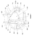
- left inner shell (111) and right inner shell (112) are three positioning screw bolts (113) and screw holes (114) (as shown in Figure-7).
- Left inner shell (111) and right inner shell (112) are fixed together by putting positioning screw bolts (113) into the screw holes (114), forming a chamber inside inner shell (110) to place handle set and grinding set.
- Plugs (118) may be applied to each screw hole to seal the holes.
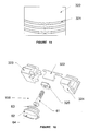
- matching outer rim (115) see Figure-14
- inner rim (116) see Figure-7) at where left inner shell (111) and right inner shell (112) contact.
- Outer rim (115) matches inner rim (116) together to seal the right and left inner shells to prevent the particles from leaking out.
- matching outer rim and inner rim can also be applied to left outer shell (121) and right outer shell (122) where they contact so that left outer shell (121) and right outer shell (122) are sealed to prevent outside dirt from entering the shell.
- inlet (124) matching where the material chamber (1) is, for feeding the material particles into the material chamber.
- a removable cover (20) on the inlet (120) which will easily cover inlet (124) after the particles are fed into the chamber to prevent outside dirt from entering the shell.
- Sealing rim (23) has the same shape as inlet (124) so that cover (20) can cover inlet (124) completely.
- step extension (25) whose size is slightly larger than the inlet (124) so that after the sealing rim (23) is zipped into the inlet (124) it can clutch into the inlet and stay in the position.
- an extension handle (24) on cover (20) is on the outside of the outer shell (120). Pulling the extension handle (24) out of shell will pull the cover (20) and separate the sealing rim (23) which is embedded in the inlet (124) to move away from the inlet. Then the particles can be fed into the material chamber (1) from the inlet (124). At this time the fitting axis (21) will not fall apart from the axis hole (125). So when the inlet (124) is open, the cover (20) will not be broken away from outer shell (120). This is very convenient.
- the handle set (200) includes mounted handle (210) and motion handle (220).
- the lower part of the mounted handle (210) and motion handle (220) are both inside the shell and the upper part of both stretch out of the shell. It is recommended that the mounted handle (210) and motion handle (220) positioned in the central plane of the shell (100).
- the mounted handle (210) and motion handle (220) are positioned opposing each other.
- the sliding resistant layer (201) been made from rubber and has the same contour as the handles so that it will fit into the notches on the sides of handles (210 and 220) to make sure the contour of the handles is smooth yet sliding resistant. Thus the user will not slide when holding the handles.
- the lower part of the mounted handle is fixed into the fixing groove (211) inside the inner shell, thus it is not going to move away from the shell.
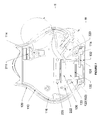
- FIG. 2 , 3 , 4 , 7 , and 10 there is a driving axis (3) at the lower end of motion handle (220).
- the spinning center i.e. the driving axis 3
- the arm of the motion handle where the force is applied will be longer, reducing the actual force been applied.
- the elastic repositioning unit selected in this implementation is a twisted spring (40).
- One end of the twisted spring (not shown in the figure) is fixed to the lower end of the motion handle (220), the other end (42) of the twisted spring is fixed to the inner shell (110). It is recommended that the center ring (43) of the spring be placed on the driving axis (3) so that it is easier to place the twisted spring (40) inside the chamber.
- the grinding set includes sector unit (310) and grinding unit (320).
- the sector unit includes a sector cylinder (311). On the sector cylinder (311) there are multiple parallel teeth (312).
- the sector unit has a spinning axis (313). This spinning axis (313) is at the rotation center of the sector cylinder (311) of the sector unit and is vertical to the plane of the motion handle (220) and mounted handle (210).
- the sector unit (310) can spin along the spinning axis (313) in the same plane as the motion handle (220) and mounted handle (210).
- This spinning axis (313) can be placed the same way as the driving axis that is at the lower end of the motion handle so that the sector unit (310) can spin inside the shell. It is recommended that that the teeth (312) on the sector cylinder (311) placed on a tooth unit (314), and then install the tooth unit (314) on the sector cylinder (311).
- This tooth unit (314) has the same curve as the sector cylinder (311). Its side with the teeth (312) faces the outside of the sector cylinder (311), i.e., away from the spinning center of the sector cylinder.
- tooth unit (314) can be made from wear resistant substances, such as cast iron.
- the sector unit (310) can be made from cheap substances such as plastic.
- teeth (312) have a great grinding performance while it is not needed for the whole sector unit been made from wear resistant substances, reducing the cost. It is also possible to choose different substances of tooth unit (314) based on the material that is to be grinded. When grinding salt particles, tooth unit (314) made of ceramic can be used to avoid the erosion of the salt to the metal, while tooth unit (314) made of metal can be used when grinding pepper particles.
- the driving set can be the slot/shaft combination between the lower part of the motion handle and the sector unit (310).
- a slot (51) can be placed at the lower end of motion handle (220).
- the sector unit (310) can be placed into this slot (51) so that the sector cylinder (311) and the spinning axis (313) of the sector unit (310) are placed on the two sides of the motion handle (220).
- the sector unit (310) will swing along the spinning axis (313) inside the shell.
- the sector unit (310) is also forced to swing back and forth along the spinning axis (313) by the driving set.
- the grinding unit (320) is mounted inside the inner shell (110), between the material chamber (1) and the sector surface (311).
- all the fixed teeth (311) can be placed onto a fixed tooth unit (322).
- the fixed tooth unit (322) will then be embedded onto the grinding unit to make sure to keep both the wear resistance and the low cost of the unit.
- Inside the inner shell there is a throat (106) on top of the grinding unit (320) connecting the material chamber (1) to the fixed teeth (321).
- the grinding unit (320) is close to the sector cylinder (311) and is to the lower outer side of the sector surface.
- the shape of the sector cylinder (311) on the center plane of the shell is a sector, when the sector surface (311) of the sector unit move along the spinning axis (313), the sector surface (311) keeps on the arc of its rim. Thus the distance between the sector surface (311) and the fixed teeth (321) will not change.
- the distance between the fixed teeth (321) of the grinding unit and the parallel teeth (312) of the tooth unit should be adjusted appropriately. It is better to be smaller than the size of the feeding particles, and the fixed teeth (321) of the grinding unit should face the parallel teeth (312) but should not touch them.
- teeth (312) lean towards the grinding unit (320) so that it is easier to smash the particles.
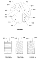
- the shape of teeth (312) can be axial, i.e., column teeth, as shown in Figure 6a . Or it can form an angle with the central axis of the gear, i.e., beveled teeth, as shown in Figure 6b . It is recommended that the teeth is placed crossed beveled, as shown in Figure 6c . This way the particles falling into the tooth aperture of teeth (312) will slide into the center of the tooth unit (314) through the tooth aperture. When grinding, teeth (312) will produce forces from two different sides on the particles so that it is more stable instead of moving around.
- the fixed teeth (321) can be rectangle in sectional view.
- each tooth is an arc as shown in Figure 15 so that when the teeth unit (314) moves, teeth (312) will push the particles to the center of the fixed teeth (321), improving the efficiency of grinding.
- the said grinding unit (320) is placed in a grinding unit slot (109) inside the inner shell (110).
- the slot (131) faces sector surface (311).
- adjusting screw bolt (108) on the inner shell.
- the screw bolt (108) matches into the grinding unit (320). Its end is fixed into the inner shell (110) and stretches outside the outer shell (120).
- the adjusting screw bolt can include bolt (61) and adjustment handle (62). Fit the end of the screw bolt (61) into the adjustment handle (62).
- the nut (63) works together with inner shell (110) so that the adjustment handle (62) is fixed on the shell and can only move on the axial direction.
- grinding unit (320) can be formed by left part (323) and right part (324).
- Screw bolt (61) can stretch into the inside of grinding unit (320) to match with the screw hole in the screw nut (325). Rotating the adjustment handle (62) will drive the bolt (61) to rotate, thus forcing the grinding unit (320) to move inside the grinding unit slot (109), and changing the distance between the fixed teeth (321) and the parallel teeth (312).
- a particle removing column (103) can be set up inside the shell.
- This particle removing column (103) is under the sector cylinder.
- This particle removing surface (104) matches the sector surface (311) so that the particle removing surface (104) is closely adjacent to the outside of the sector surface (311) and has the same axis as the sector surface (311).
- particle removing surface (104) is parallel to the sector surface (311) and the distance between particle removing surface (104) and the sector surface (311) is small enough, may even be directly contacted with each other.
- the particles attaching to sector surface (311) or stuck in the parallel teeth (312) will be removed and fall directly into the outlet (102), thus preventing the particles sticking to the sector surface (311) from accumulating in the space under the sector unit and clogging the sector unit and stopping it from moving.
- the particles removed from the particle removing column (103) will fall into outlet (102) through the aperture (105), preventing them from accumulating in the shell (110) and clogging the sector cylinder (311).
- the slot (130) has a slot cover (140) that can cover outlet (102). Slot cover (140) can glide in the slot (130) to open or close outlet (102).
- the slot cover (140) can be L shape, including the vertical cover (142) and horizontal cover (141).
- Slot (130) can also be L shape, including a horizontal slot (131) at the outlet (102) at the bottom of the shell and the vertical slot (132) on the inner surface of the inner shell.
- the horizontal cover (141) can glide in the horizontal slot (131) and cover the outlet (102) that is at the bottom of the shell.
- the vertical cover (142) can glide in the vertical slot (132) along the inner shell surface.
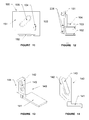
- a vertical slot (143) on the vertical cover (142) of the slot cover see Figure 13 .
- a driving shaft (223) at the side of the sector unit (310) see Figure 10 ).
- This shaft (223) cooperates with the vertical slot (143) so that it can slide inside the vertical slot (143).
- the shaft (223) on the side of the sector unit (310) will also move back and forth along the spinning axis.
- the movement of the this shaft (223) can be decoupled into the vertical movement along the vertical slot (143) and the horizontal movement that is at the right angle to the vertical slot (143).
- the slot (130) consists of the slot (133) on the inner shell and the slot disc (150).
- the slot disc (150) has a vertical disc (151) and a horizontal disc (152). Slot (133) was set on the corresponding positions of the inner shell's inner surface and bottom. The vertical disc (151) of the slot disc (150) is embedded in the slot (133).
- the vertical disc (151) of the slot disc covers the depressed hole to form a vertical slot (132) of the slot, so that the vertical cover (142) of the slot cover can slide in it.
- the horizontal disc (152) of the slot disc and the bottom of the inner shell forms the horizontal slot (131) of the slot, so that the horizontal cover (141) of the slot cover can slide in it.
- the shaft is the shaft (53) that is on the lower end of the motion handle and is used to fix shaft cap (54), i.e., the cap (54) at the lower end of the motion handle stretches out to the vertical slot (143) of the slot cover.
- a collection box (5) can be placed at the bottom of the outer shell (120).
- This collection box (5) is placed under the outlet (102) and matches into the bottom of the outer shell (120). So the collection box (5) can be installed at the bottom of the outer shell using screw or buckle.
- the finished particles discharged from the outlet (102) can be collected in the collection box (5).
- the user can stop operating the handle set and take the collection box out of the outer shell and use the finished product.
- the single-handed vertical solid material grinder there is another implementation example of the single-handed vertical solid material grinder.
- the difference between this one and the one that illustrated above is the driving mechanism of the motion handle and the sector unit.
- the spinning axis (313) of the sector unit is the same as the driving axis (3) of the motion handle, and is at the rotation center of the sector cylinder (311).
- the sector cylinder (311) of the sector unit will move along its axis (the spinning axis (313) and driving axis (3)) back and forth.
- the teeth on the sector cylinder will sweep over the fixed teeth on the grinding unit (320).
- the particles will also get grinded this way to achieve the grinding result.
- the shaft that stretches into the vertical slot of the slot cover can also be set at the side of the sector unit.
Landscapes
- Engineering & Computer Science (AREA)
- Mechanical Engineering (AREA)
- Food Science & Technology (AREA)
- Finish Polishing, Edge Sharpening, And Grinding By Specific Grinding Devices (AREA)
- Food-Manufacturing Devices (AREA)
Claims (12)
- Vertikale Einhandfeststoffmühle, beinhaltend:eine Hülle (100), die einen Materialeinlass (124) und einen Auslass (102) aufweist, welche eine Materialkammer (1) besitzt, die die festen Materialpartikel enthält und mit dem Einlass (124) verbunden ist,ein Griffset (200) mit einem Bewegungsgriff (220) und einem Anbaugriff (210), wobei sich der obere Teil des Bewegungsgriffs (220) und der Anbaugriff (210) außerhalb der Hülle (100) erstrecken, wobei der untere Bereich des Anbaugriffs (210) im Inneren der Hülle (100) befestigt ist, wobei der untere Bereich des Bewegungsgriffs (220) eine Antriebsachse (3) aufweist, die im Inneren der Hülle (100) befestigt ist, wobei sich der Bewegungsgriff (220) um die Antriebsachse (3) vor und zurück bewegen kann, wobei es zwischen dem Bewegungsgriff (220) und der Hülle (100) eine elastische Rückstelleinheit (40) gibt, die den Bewegungsgriff (220) von dem Anbaugriff (210) fort drückt,einen Mahlsatz im Inneren der Hülle (100), der eine Bogenstückeinheit (310) mit einer Bogenstückfläche (311) und eine Mahleinheit (320) beinhaltet, die außerhalb der Bogenstückfläche (311) angeordnet ist, wobei es auf der Bogenstückfläche (311) zahlreiche parallele Zähne (312) gibt, wobei eine Drehachse (313) am Drehmittelpunkt der Bogenstückeinheit (310) im Inneren der Hülle (100) befestigt und senkrecht zur Ebene des Bewegungsgriffs (220) und des Anbaugriffs (210) ist, wobei wenigstens ein fester Zahn (321) der Mahleinheit (320) zu den zahlreichen parallelen Zähnen (312) passt,eine Öffnung (106), die von der Materialkammer (1) zu dem wenigstens einen festen Zahn (321) der Mahleinheit (320) oberhalb der Mahleinheit (320) in der Hülle (100) führt, undeinen Auslass unterhalb des wenigstens einen festen Zahns (321) der Mahleinheit (320) in der Hülle (100),dadurch gekennzeichnet, dass die vertikale Einhandfeststoffmühle des Weiteren ein Antriebsset beinhaltet, das zwischen dem Bewegungsgriff (220) und der Bogenstückeinheit (310) vorgesehen ist, die Bogenstückeinheit (310) um die Drehachse (313) vor und zurück bewegt und einen Achs-(53) und Schlitz-(51)satz zwischen der Bogenstückeinheit (310) und dem unteren Abschnitt des Bewegungsgriffs (220) beinhaltet.
- Vertikale Einhandfeststoffmühle nach Anspruch 1, wobei die Drehachse (313) der Bogenstückeinheit (310) und die Antriebsachse (3) des Bewegungsgriffs (220) einander überlappen, wobei die Bogenstückeinheit (310) mittels des Antriebssets in den Bewegungsgriff (220) eingesetzt ist.
- Vertikale Einhandfeststoffmühle nach Anspruch 1 oder 2, wobei an dem Auslass (102) der Hülle (100) ein horizontaler Schlitz (131) vorgesehen ist, wobei der Schlitz (131) eine Schlitzabdeckung (140) besitzt, die den Auslass (102) abdecken kann, wobei die Schlitzabdeckung (140) eine vertikale Schiene (142) besitzt, wobei es in der Bogenstückeinheit (310) eine Antriebsachse (223) gibt, die mit der vertikalen Schiene (142) zusammen passt, wobei die Antriebsachse (223) die Schlitzabdeckung (140) antreibt, um sich in dem Schlitz (131) vor und zurück zu bewegen.
- Vertikale Einhandfeststoffmühle nach Anspruch 3, wobei es in der Innenfläche der Hülle (100) eine Nut gibt, wobei es eine Nutabdeckung auf der Nut gibt, wobei es zwischen der Nutabdeckung und der Nut einen Schlitz gibt, wobei eine Bogenstücknut (135) in der Nutabdeckung die gleiche Rotationsachse wie die Bogenstückeinheit (310) besitzt, wobei die Antriebsachse (223) durch die Bogenstücknut (135) ragt und in den vertikalen Schlitz (143) der Schlitzabdeckung (140) eingreift.
- Vertikale Einhandfeststoffmühle nach Anspruch 3, wobei es im Inneren der Hülle (100) unter der Bogenstückeinheit (310) eine Partikel entfernende Säule (103) gibt, wobei die Partikel entfernende Säule (103) eine Partikel entfernende Oberfläche (104) besitzt, die der Bogenstückfläche (311) gegenüberliegt und den gleichen Mittelpunkt wie die Bogenstückfläche (311) besitzt, wobei die Partikel entfernende Oberfläche (104) sich gerade außerhalb der Bogenstückfläche (311) befindet.
- Vertikale Einhandfeststoffmühle nach Anspruch 1 oder 2, wobei die elastische Rückstellungseinheit eine Feder (40) zwischen der Bogenstückfläche (311) und der Hülle (100) ist.
- Vertikale Einhandfeststoffmühle nach Anspruch 1 oder 2, wobei die Mahleinheit (320) in der Mahleinheitskammer (109) im Inneren der Hülle (100) angeordnet ist und der Bogenstückfläche (311) gegenüberliegt, wobei eine Abstandseinstellungsschraube (108) an der Mahleinheit (320) in der Hülle (100) vorgesehen ist, um den Abstand zwischen dem festen Zahn (321) und den Zähnen (312) der Bogenstückfläche (311) einzustellen.
- Vertikale Einhandfeststoffmühle nach Anspruch 1 oder 2, wobei die Hülle (100) eine äußere Hülle (120) und eine innere Hülle (110) aufweist, wobei die Materialkammer (1) sich zwischen der äußeren Hülle (120) und der inneren Hülle (110) befindet, wobei sowohl der Einlass (124) als auch der Auslass (102) an der äußeren Hülle (120) vorgesehen sind, wobei die Öffnung (105), die die Materialkammer (1) und die Mahleinheit (320) verbindet, in der inneren Hülle (110) vorgesehen ist und wobei das Griffset (200) und das Mahlwerk im Inneren der inneren Hülle (110) vorgesehen sind.
- Vertikale Einhandfeststoffmühle nach Anspruch 8, wobei es eine abdichtende Abdeckung (20) an dem Einlass gibt, wobei die abdichtende Abdeckung (20) an einem Ende eine Befestigungsachse aufweist, die an der äußeren Hülle (120) befestigt ist, wobei an dem anderen Ende eine Verlängerungskante (23) vorgesehen ist, die den Einlass (124) abdeckt.
- Vertikale Einhandfeststoffmühle nach Anspruch 1, wobei es eine Zahneinheit (314) auf der Bogenstückfläche (311) der Bogenstückeinheit (310) gibt, wobei die Zähne (312) der Bogenstückfläche (311) an der Außenseite der Zahneinheit (314) angeordnet sind.
- Vertikale Einhandfeststoffmühle nach Anspruch 1, wobei es unter dem Auslass (102) an der äußeren Hülle (120) ein Sammelbehältnis (5) gibt, um die erzeugten Partikel zu sammeln.
- Vertikale Einhandfeststoffmühle nach Anspruch 1, wobei es an dem Bewegungsgriff (220) des Griffsatzes (200) eine gleitsichere Abdeckung (201) gibt.
Applications Claiming Priority (2)
| Application Number | Priority Date | Filing Date | Title |
|---|---|---|---|
| CN2008100684049A CN101322621B (zh) | 2008-07-04 | 2008-07-04 | 单手立式固体调料研磨器 |
| PCT/CN2009/071943 WO2010000162A1 (zh) | 2008-07-04 | 2009-05-25 | 单手立式固体调料研磨器 |
Publications (3)
| Publication Number | Publication Date |
|---|---|
| EP2305083A1 EP2305083A1 (de) | 2011-04-06 |
| EP2305083A4 EP2305083A4 (de) | 2012-03-28 |
| EP2305083B1 true EP2305083B1 (de) | 2013-07-03 |
Family
ID=40186444
Family Applications (1)
| Application Number | Title | Priority Date | Filing Date |
|---|---|---|---|
| EP09771932.2A Not-in-force EP2305083B1 (de) | 2008-07-04 | 2009-05-25 | Einhändig betätigte vertikale mühle für feste aromastoffe |
Country Status (4)
| Country | Link |
|---|---|
| US (1) | US8205816B2 (de) |
| EP (1) | EP2305083B1 (de) |
| CN (1) | CN101322621B (de) |
| WO (1) | WO2010000162A1 (de) |
Families Citing this family (1)
| Publication number | Priority date | Publication date | Assignee | Title |
|---|---|---|---|---|
| CN101322621B (zh) * | 2008-07-04 | 2010-12-22 | 汪恩光 | 单手立式固体调料研磨器 |
Family Cites Families (17)
| Publication number | Priority date | Publication date | Assignee | Title |
|---|---|---|---|---|
| CH225319A (fr) * | 1942-12-26 | 1943-01-31 | L Etang Marc Matthey De | Moulin à sel de table. |
| FR911245A (fr) * | 1945-06-05 | 1946-07-02 | Moulin à sel de table | |
| US5988543A (en) * | 1998-12-16 | 1999-11-23 | Yienn Lih Enterprise Co., Ltd. | Pepper grinding tool |
| US6672524B1 (en) * | 2000-09-07 | 2004-01-06 | Chef'n Corporation | Multiple chamber condiment grinder |
| JP2002263011A (ja) * | 2001-03-13 | 2002-09-17 | Japan Poorekkusu Kk | 香辛料ひき器 |
| CN2496372Y (zh) * | 2001-08-16 | 2002-06-26 | 汪恩光 | 胡椒粒压碎器 |
| CN2500998Y (zh) * | 2001-08-16 | 2002-07-17 | 汪恩光 | 多功能刨冰、切碎及搞拌器 |
| US6871808B2 (en) * | 2002-04-16 | 2005-03-29 | Chef'n Corporation | Apparatus for grinding material, such as spice or grain |
| US6568616B1 (en) * | 2002-10-11 | 2003-05-27 | Samson Bright Industrial Co. Ltd. | Hand-held condiment grinder |
| US6877684B2 (en) * | 2003-07-29 | 2005-04-12 | Yienn Lih Enterprise Co., Ltd. | Grinding tool |
| US6948671B2 (en) * | 2003-12-17 | 2005-09-27 | Ming-Feng Wu | Pepper grinder operable with one hand and by pressing and releasing a lever repeatedly |
| NZ538485A (en) * | 2005-02-25 | 2007-09-28 | Click Clack Ltd | A drive mechanism for a manual grinder |
| CN201008517Y (zh) * | 2007-01-26 | 2008-01-23 | 张雅斌 | 胡椒碾磨器 |
| JP5254350B2 (ja) * | 2007-11-09 | 2013-08-07 | シェフン コーポレイション | モジュラー粉砕コア及びこれを備える粉砕装置 |
| CN101322621B (zh) * | 2008-07-04 | 2010-12-22 | 汪恩光 | 单手立式固体调料研磨器 |
| CN201223318Y (zh) * | 2008-07-04 | 2009-04-22 | 汪恩光 | 单手立式固体调料研磨器 |
| CN201481159U (zh) * | 2009-06-15 | 2010-05-26 | 鸭都喇利家品有限公司 | 多用固体调料研磨器 |
-
2008
- 2008-07-04 CN CN2008100684049A patent/CN101322621B/zh not_active Expired - Fee Related
-
2009
- 2009-05-25 WO PCT/CN2009/071943 patent/WO2010000162A1/zh not_active Ceased
- 2009-05-25 EP EP09771932.2A patent/EP2305083B1/de not_active Not-in-force
- 2009-05-25 US US12/679,308 patent/US8205816B2/en not_active Expired - Fee Related
Also Published As
| Publication number | Publication date |
|---|---|
| CN101322621B (zh) | 2010-12-22 |
| EP2305083A1 (de) | 2011-04-06 |
| US20100219277A1 (en) | 2010-09-02 |
| CN101322621A (zh) | 2008-12-17 |
| US8205816B2 (en) | 2012-06-26 |
| WO2010000162A1 (zh) | 2010-01-07 |
| EP2305083A4 (de) | 2012-03-28 |
Similar Documents
| Publication | Publication Date | Title |
|---|---|---|
| JP5097005B2 (ja) | 香料破砕グラインダー及びその自動開閉制御装置 | |
| EP2596730B1 (de) | Einstellung einer schleifblockerleichterung zur schleifungsverfeinerung | |
| JP2020182639A (ja) | 粒状食品用ミル | |
| KR101154088B1 (ko) | 양념 분쇄용기 | |
| CN203424844U (zh) | 食物研磨器 | |
| JP3326556B2 (ja) | 製粉機 | |
| CN218590718U (zh) | 一种粉碎机刀片组 | |
| EP2305083A1 (de) | Einhändig betätigte vertikale mühle für feste aromastoffe | |
| CN107457052B (zh) | 一种中草药破碎机 | |
| JP2000070743A (ja) | 製粉機 | |
| KR20120002370U (ko) | 다용도 분쇄기 | |
| CN210787620U (zh) | 一种用于化妆品原料的粉碎机 | |
| CN204091807U (zh) | 一种多用食品加工机 | |
| JP3039887B2 (ja) | 電気コーヒー沸かし器 | |
| JP2002263012A (ja) | 電動式薬味類碾砕器 | |
| CN2498965Y (zh) | 咖啡研磨机结构改良 | |
| KR100825818B1 (ko) | 칼날 조절이 용이한 빙삭기 | |
| CN110639936A (zh) | 一种粉碎装置 | |
| CN220713722U (zh) | 一种料仓外部可调节粗细的电动研磨器 | |
| KR102157660B1 (ko) | 청소가 용이한 분쇄기 | |
| CN211329762U (zh) | 一种用于制药的高效粉碎装置 | |
| CN209252566U (zh) | 磨豆机 | |
| AU781907B2 (en) | Food grinder | |
| CN201223318Y (zh) | 单手立式固体调料研磨器 | |
| CN207981327U (zh) | 一种中草药破碎机 |
Legal Events
| Date | Code | Title | Description |
|---|---|---|---|
| PUAI | Public reference made under article 153(3) epc to a published international application that has entered the european phase |
Free format text: ORIGINAL CODE: 0009012 |
|
| 17P | Request for examination filed |
Effective date: 20110114 |
|
| AK | Designated contracting states |
Kind code of ref document: A1 Designated state(s): AT BE BG CH CY CZ DE DK EE ES FI FR GB GR HR HU IE IS IT LI LT LU LV MC MK MT NL NO PL PT RO SE SI SK TR |
|
| AX | Request for extension of the european patent |
Extension state: AL BA RS |
|
| DAX | Request for extension of the european patent (deleted) | ||
| A4 | Supplementary search report drawn up and despatched |
Effective date: 20120224 |
|
| RIC1 | Information provided on ipc code assigned before grant |
Ipc: A47J 42/34 20060101AFI20120220BHEP Ipc: A47J 43/04 20060101ALI20120220BHEP |
|
| GRAP | Despatch of communication of intention to grant a patent |
Free format text: ORIGINAL CODE: EPIDOSNIGR1 |
|
| GRAS | Grant fee paid |
Free format text: ORIGINAL CODE: EPIDOSNIGR3 |
|
| GRAA | (expected) grant |
Free format text: ORIGINAL CODE: 0009210 |
|
| AK | Designated contracting states |
Kind code of ref document: B1 Designated state(s): AT BE BG CH CY CZ DE DK EE ES FI FR GB GR HR HU IE IS IT LI LT LU LV MC MK MT NL NO PL PT RO SE SI SK TR |
|
| REG | Reference to a national code |
Ref country code: GB Ref legal event code: FG4D |
|
| REG | Reference to a national code |
Ref country code: AT Ref legal event code: REF Ref document number: 619224 Country of ref document: AT Kind code of ref document: T Effective date: 20130715 Ref country code: CH Ref legal event code: EP |
|
| REG | Reference to a national code |
Ref country code: IE Ref legal event code: FG4D |
|
| REG | Reference to a national code |
Ref country code: DE Ref legal event code: R096 Ref document number: 602009016903 Country of ref document: DE Effective date: 20130829 |
|
| PG25 | Lapsed in a contracting state [announced via postgrant information from national office to epo] |
Ref country code: SI Free format text: LAPSE BECAUSE OF FAILURE TO SUBMIT A TRANSLATION OF THE DESCRIPTION OR TO PAY THE FEE WITHIN THE PRESCRIBED TIME-LIMIT Effective date: 20130703 |
|
| REG | Reference to a national code |
Ref country code: AT Ref legal event code: MK05 Ref document number: 619224 Country of ref document: AT Kind code of ref document: T Effective date: 20130703 |
|
| REG | Reference to a national code |
Ref country code: NL Ref legal event code: VDEP Effective date: 20130703 |
|
| REG | Reference to a national code |
Ref country code: LT Ref legal event code: MG4D |
|
| PG25 | Lapsed in a contracting state [announced via postgrant information from national office to epo] |
Ref country code: LT Free format text: LAPSE BECAUSE OF FAILURE TO SUBMIT A TRANSLATION OF THE DESCRIPTION OR TO PAY THE FEE WITHIN THE PRESCRIBED TIME-LIMIT Effective date: 20130703 Ref country code: NO Free format text: LAPSE BECAUSE OF FAILURE TO SUBMIT A TRANSLATION OF THE DESCRIPTION OR TO PAY THE FEE WITHIN THE PRESCRIBED TIME-LIMIT Effective date: 20131003 Ref country code: BE Free format text: LAPSE BECAUSE OF FAILURE TO SUBMIT A TRANSLATION OF THE DESCRIPTION OR TO PAY THE FEE WITHIN THE PRESCRIBED TIME-LIMIT Effective date: 20130703 Ref country code: AT Free format text: LAPSE BECAUSE OF FAILURE TO SUBMIT A TRANSLATION OF THE DESCRIPTION OR TO PAY THE FEE WITHIN THE PRESCRIBED TIME-LIMIT Effective date: 20130703 Ref country code: IS Free format text: LAPSE BECAUSE OF FAILURE TO SUBMIT A TRANSLATION OF THE DESCRIPTION OR TO PAY THE FEE WITHIN THE PRESCRIBED TIME-LIMIT Effective date: 20131103 Ref country code: SE Free format text: LAPSE BECAUSE OF FAILURE TO SUBMIT A TRANSLATION OF THE DESCRIPTION OR TO PAY THE FEE WITHIN THE PRESCRIBED TIME-LIMIT Effective date: 20130703 Ref country code: CY Free format text: LAPSE BECAUSE OF FAILURE TO SUBMIT A TRANSLATION OF THE DESCRIPTION OR TO PAY THE FEE WITHIN THE PRESCRIBED TIME-LIMIT Effective date: 20130710 Ref country code: HR Free format text: LAPSE BECAUSE OF FAILURE TO SUBMIT A TRANSLATION OF THE DESCRIPTION OR TO PAY THE FEE WITHIN THE PRESCRIBED TIME-LIMIT Effective date: 20130703 Ref country code: PT Free format text: LAPSE BECAUSE OF FAILURE TO SUBMIT A TRANSLATION OF THE DESCRIPTION OR TO PAY THE FEE WITHIN THE PRESCRIBED TIME-LIMIT Effective date: 20131104 |
|
| PG25 | Lapsed in a contracting state [announced via postgrant information from national office to epo] |
Ref country code: FI Free format text: LAPSE BECAUSE OF FAILURE TO SUBMIT A TRANSLATION OF THE DESCRIPTION OR TO PAY THE FEE WITHIN THE PRESCRIBED TIME-LIMIT Effective date: 20130703 Ref country code: LV Free format text: LAPSE BECAUSE OF FAILURE TO SUBMIT A TRANSLATION OF THE DESCRIPTION OR TO PAY THE FEE WITHIN THE PRESCRIBED TIME-LIMIT Effective date: 20130703 Ref country code: NL Free format text: LAPSE BECAUSE OF FAILURE TO SUBMIT A TRANSLATION OF THE DESCRIPTION OR TO PAY THE FEE WITHIN THE PRESCRIBED TIME-LIMIT Effective date: 20130703 Ref country code: GR Free format text: LAPSE BECAUSE OF FAILURE TO SUBMIT A TRANSLATION OF THE DESCRIPTION OR TO PAY THE FEE WITHIN THE PRESCRIBED TIME-LIMIT Effective date: 20131004 Ref country code: PL Free format text: LAPSE BECAUSE OF FAILURE TO SUBMIT A TRANSLATION OF THE DESCRIPTION OR TO PAY THE FEE WITHIN THE PRESCRIBED TIME-LIMIT Effective date: 20130703 Ref country code: ES Free format text: LAPSE BECAUSE OF FAILURE TO SUBMIT A TRANSLATION OF THE DESCRIPTION OR TO PAY THE FEE WITHIN THE PRESCRIBED TIME-LIMIT Effective date: 20131014 |
|
| PG25 | Lapsed in a contracting state [announced via postgrant information from national office to epo] |
Ref country code: CY Free format text: LAPSE BECAUSE OF FAILURE TO SUBMIT A TRANSLATION OF THE DESCRIPTION OR TO PAY THE FEE WITHIN THE PRESCRIBED TIME-LIMIT Effective date: 20130703 |
|
| PG25 | Lapsed in a contracting state [announced via postgrant information from national office to epo] |
Ref country code: DK Free format text: LAPSE BECAUSE OF FAILURE TO SUBMIT A TRANSLATION OF THE DESCRIPTION OR TO PAY THE FEE WITHIN THE PRESCRIBED TIME-LIMIT Effective date: 20130703 Ref country code: EE Free format text: LAPSE BECAUSE OF FAILURE TO SUBMIT A TRANSLATION OF THE DESCRIPTION OR TO PAY THE FEE WITHIN THE PRESCRIBED TIME-LIMIT Effective date: 20130703 Ref country code: SK Free format text: LAPSE BECAUSE OF FAILURE TO SUBMIT A TRANSLATION OF THE DESCRIPTION OR TO PAY THE FEE WITHIN THE PRESCRIBED TIME-LIMIT Effective date: 20130703 Ref country code: RO Free format text: LAPSE BECAUSE OF FAILURE TO SUBMIT A TRANSLATION OF THE DESCRIPTION OR TO PAY THE FEE WITHIN THE PRESCRIBED TIME-LIMIT Effective date: 20130703 Ref country code: CZ Free format text: LAPSE BECAUSE OF FAILURE TO SUBMIT A TRANSLATION OF THE DESCRIPTION OR TO PAY THE FEE WITHIN THE PRESCRIBED TIME-LIMIT Effective date: 20130703 |
|
| PLBE | No opposition filed within time limit |
Free format text: ORIGINAL CODE: 0009261 |
|
| STAA | Information on the status of an ep patent application or granted ep patent |
Free format text: STATUS: NO OPPOSITION FILED WITHIN TIME LIMIT |
|
| PG25 | Lapsed in a contracting state [announced via postgrant information from national office to epo] |
Ref country code: IT Free format text: LAPSE BECAUSE OF FAILURE TO SUBMIT A TRANSLATION OF THE DESCRIPTION OR TO PAY THE FEE WITHIN THE PRESCRIBED TIME-LIMIT Effective date: 20130703 |
|
| 26N | No opposition filed |
Effective date: 20140404 |
|
| REG | Reference to a national code |
Ref country code: DE Ref legal event code: R097 Ref document number: 602009016903 Country of ref document: DE Effective date: 20140404 |
|
| PG25 | Lapsed in a contracting state [announced via postgrant information from national office to epo] |
Ref country code: LU Free format text: LAPSE BECAUSE OF FAILURE TO SUBMIT A TRANSLATION OF THE DESCRIPTION OR TO PAY THE FEE WITHIN THE PRESCRIBED TIME-LIMIT Effective date: 20140525 |
|
| REG | Reference to a national code |
Ref country code: CH Ref legal event code: PL |
|
| PG25 | Lapsed in a contracting state [announced via postgrant information from national office to epo] |
Ref country code: LI Free format text: LAPSE BECAUSE OF NON-PAYMENT OF DUE FEES Effective date: 20140531 Ref country code: CH Free format text: LAPSE BECAUSE OF NON-PAYMENT OF DUE FEES Effective date: 20140531 Ref country code: MC Free format text: LAPSE BECAUSE OF FAILURE TO SUBMIT A TRANSLATION OF THE DESCRIPTION OR TO PAY THE FEE WITHIN THE PRESCRIBED TIME-LIMIT Effective date: 20130703 |
|
| REG | Reference to a national code |
Ref country code: IE Ref legal event code: MM4A |
|
| PG25 | Lapsed in a contracting state [announced via postgrant information from national office to epo] |
Ref country code: IE Free format text: LAPSE BECAUSE OF NON-PAYMENT OF DUE FEES Effective date: 20140525 |
|
| PG25 | Lapsed in a contracting state [announced via postgrant information from national office to epo] |
Ref country code: MT Free format text: LAPSE BECAUSE OF FAILURE TO SUBMIT A TRANSLATION OF THE DESCRIPTION OR TO PAY THE FEE WITHIN THE PRESCRIBED TIME-LIMIT Effective date: 20130703 |
|
| REG | Reference to a national code |
Ref country code: FR Ref legal event code: PLFP Year of fee payment: 8 |
|
| PG25 | Lapsed in a contracting state [announced via postgrant information from national office to epo] |
Ref country code: BG Free format text: LAPSE BECAUSE OF FAILURE TO SUBMIT A TRANSLATION OF THE DESCRIPTION OR TO PAY THE FEE WITHIN THE PRESCRIBED TIME-LIMIT Effective date: 20130703 |
|
| PG25 | Lapsed in a contracting state [announced via postgrant information from national office to epo] |
Ref country code: TR Free format text: LAPSE BECAUSE OF FAILURE TO SUBMIT A TRANSLATION OF THE DESCRIPTION OR TO PAY THE FEE WITHIN THE PRESCRIBED TIME-LIMIT Effective date: 20130703 Ref country code: HU Free format text: LAPSE BECAUSE OF FAILURE TO SUBMIT A TRANSLATION OF THE DESCRIPTION OR TO PAY THE FEE WITHIN THE PRESCRIBED TIME-LIMIT; INVALID AB INITIO Effective date: 20090525 |
|
| REG | Reference to a national code |
Ref country code: FR Ref legal event code: PLFP Year of fee payment: 9 |
|
| PG25 | Lapsed in a contracting state [announced via postgrant information from national office to epo] |
Ref country code: MK Free format text: LAPSE BECAUSE OF FAILURE TO SUBMIT A TRANSLATION OF THE DESCRIPTION OR TO PAY THE FEE WITHIN THE PRESCRIBED TIME-LIMIT Effective date: 20130703 |
|
| REG | Reference to a national code |
Ref country code: FR Ref legal event code: PLFP Year of fee payment: 10 |
|
| PGFP | Annual fee paid to national office [announced via postgrant information from national office to epo] |
Ref country code: FR Payment date: 20180831 Year of fee payment: 10 Ref country code: DE Payment date: 20180730 Year of fee payment: 10 |
|
| PGFP | Annual fee paid to national office [announced via postgrant information from national office to epo] |
Ref country code: GB Payment date: 20180824 Year of fee payment: 10 |
|
| REG | Reference to a national code |
Ref country code: DE Ref legal event code: R119 Ref document number: 602009016903 Country of ref document: DE |
|
| GBPC | Gb: european patent ceased through non-payment of renewal fee |
Effective date: 20190525 |
|
| PG25 | Lapsed in a contracting state [announced via postgrant information from national office to epo] |
Ref country code: DE Free format text: LAPSE BECAUSE OF NON-PAYMENT OF DUE FEES Effective date: 20191203 Ref country code: GB Free format text: LAPSE BECAUSE OF NON-PAYMENT OF DUE FEES Effective date: 20190525 |
|
| PG25 | Lapsed in a contracting state [announced via postgrant information from national office to epo] |
Ref country code: FR Free format text: LAPSE BECAUSE OF NON-PAYMENT OF DUE FEES Effective date: 20190531 |