EP2303125B1 - Spektralabbildung - Google Patents
Spektralabbildung Download PDFInfo
- Publication number
- EP2303125B1 EP2303125B1 EP09786439.1A EP09786439A EP2303125B1 EP 2303125 B1 EP2303125 B1 EP 2303125B1 EP 09786439 A EP09786439 A EP 09786439A EP 2303125 B1 EP2303125 B1 EP 2303125B1
- Authority
- EP
- European Patent Office
- Prior art keywords
- contrast agent
- contrast
- contrast agents
- image
- time
- Prior art date
- Legal status (The legal status is an assumption and is not a legal conclusion. Google has not performed a legal analysis and makes no representation as to the accuracy of the status listed.)
- Active
Links
Images

Classifications
-
- A—HUMAN NECESSITIES
- A61—MEDICAL OR VETERINARY SCIENCE; HYGIENE
- A61B—DIAGNOSIS; SURGERY; IDENTIFICATION
- A61B6/00—Apparatus for radiation diagnosis, e.g. combined with radiation therapy equipment
- A61B6/50—Clinical applications
- A61B6/504—Clinical applications involving diagnosis of blood vessels, e.g. by angiography
-
- A—HUMAN NECESSITIES
- A61—MEDICAL OR VETERINARY SCIENCE; HYGIENE
- A61B—DIAGNOSIS; SURGERY; IDENTIFICATION
- A61B5/00—Measuring for diagnostic purposes; Identification of persons
- A61B5/48—Other medical applications
- A61B5/4869—Determining body composition
-
- A—HUMAN NECESSITIES
- A61—MEDICAL OR VETERINARY SCIENCE; HYGIENE
- A61B—DIAGNOSIS; SURGERY; IDENTIFICATION
- A61B6/00—Apparatus for radiation diagnosis, e.g. combined with radiation therapy equipment
- A61B6/02—Devices for diagnosis sequentially in different planes; Stereoscopic radiation diagnosis
- A61B6/03—Computerised tomographs
- A61B6/032—Transmission computed tomography [CT]
-
- A—HUMAN NECESSITIES
- A61—MEDICAL OR VETERINARY SCIENCE; HYGIENE
- A61B—DIAGNOSIS; SURGERY; IDENTIFICATION
- A61B6/00—Apparatus for radiation diagnosis, e.g. combined with radiation therapy equipment
- A61B6/48—Diagnostic techniques
- A61B6/481—Diagnostic techniques involving the use of contrast agents
-
- A—HUMAN NECESSITIES
- A61—MEDICAL OR VETERINARY SCIENCE; HYGIENE
- A61B—DIAGNOSIS; SURGERY; IDENTIFICATION
- A61B6/00—Apparatus for radiation diagnosis, e.g. combined with radiation therapy equipment
- A61B6/48—Diagnostic techniques
- A61B6/482—Diagnostic techniques involving multiple energy imaging
-
- A—HUMAN NECESSITIES
- A61—MEDICAL OR VETERINARY SCIENCE; HYGIENE
- A61B—DIAGNOSIS; SURGERY; IDENTIFICATION
- A61B6/00—Apparatus for radiation diagnosis, e.g. combined with radiation therapy equipment
- A61B6/50—Clinical applications
- A61B6/501—Clinical applications involving diagnosis of head, e.g. neuroimaging, craniography
-
- A—HUMAN NECESSITIES
- A61—MEDICAL OR VETERINARY SCIENCE; HYGIENE
- A61B—DIAGNOSIS; SURGERY; IDENTIFICATION
- A61B6/00—Apparatus for radiation diagnosis, e.g. combined with radiation therapy equipment
- A61B6/50—Clinical applications
- A61B6/507—Clinical applications involving determination of haemodynamic parameters, e.g. perfusion CT
-
- A—HUMAN NECESSITIES
- A61—MEDICAL OR VETERINARY SCIENCE; HYGIENE
- A61P—SPECIFIC THERAPEUTIC ACTIVITY OF CHEMICAL COMPOUNDS OR MEDICINAL PREPARATIONS
- A61P43/00—Drugs for specific purposes, not provided for in groups A61P1/00-A61P41/00
-
- A—HUMAN NECESSITIES
- A61—MEDICAL OR VETERINARY SCIENCE; HYGIENE
- A61K—PREPARATIONS FOR MEDICAL, DENTAL OR TOILETRY PURPOSES
- A61K49/00—Preparations for testing in vivo
-
- A—HUMAN NECESSITIES
- A61—MEDICAL OR VETERINARY SCIENCE; HYGIENE
- A61M—DEVICES FOR INTRODUCING MEDIA INTO, OR ONTO, THE BODY; DEVICES FOR TRANSDUCING BODY MEDIA OR FOR TAKING MEDIA FROM THE BODY; DEVICES FOR PRODUCING OR ENDING SLEEP OR STUPOR
- A61M5/00—Devices for bringing media into the body in a subcutaneous, intra-vascular or intramuscular way; Accessories therefor, e.g. filling or cleaning devices, arm-rests
- A61M5/007—Devices for bringing media into the body in a subcutaneous, intra-vascular or intramuscular way; Accessories therefor, e.g. filling or cleaning devices, arm-rests for contrast media
Definitions
- CT computed tomography
- a computed tomography (CT) scanner has been used to capture perfusion information, such as flow through vascular tissue, which can be used to facilitate diagnosing patients.
- perfusion information such as flow through vascular tissue
- a brain perfusion scan provides information that can be used to facilitate identifying mal-perfusion in stroke patients.
- CTP computed tomography perfusion
- a conventional computed tomography perfusion (CTP) procedure includes intravenously administering a contrast agent bolus to a patient, which causes the x-ray density of the brain to temporarily increase as the contrast agent is taken up and flows through and washes out of the vascular structure of the brain, and performing a time series of CT scans of the patient's brain.
- the captured data can be used to trace the contrast agent as it flows through the brain and identify ischemic tissue and/or differentiate between irreversibly damaged or necrotic tissue (the core of the infarct) and potentially reversibly damaged or at-risk tissue (the penumbra of the infarct).
- the differences in the absorption in the time series provide relative measures of mean transition time (MTT), cerebral blood volume (CBV) and cerebral blood-flow (CBF).
- This may have limited reliability since the de-convolution process requires operator selection of a reference vessel for the input function, and the selection is prone to error.
- the accuracy of such a technique is limited since the pharmacokinetics is a complex function and the information carried by the CTP measurements are not well-suited for deriving the hemodynamic and perfusion parameters.
- the contrast agent bolus is only temporarily present within the patient, and the time interval during which the contrast agent can be visualized is limited by the residence time of the contrast agent within the patient.
- a contrast agent based CT procedure can be used to identify hyper and/or hypo perfused regions of the liver during the aortic (contrast uptake) phase, the portal venous (contrast wash out) phase, and/or the equilibrium (no contrast) phase.
- a contrast agent based CT procedure
- multiple scans e.g., 3 to 5 scans
- patient dose may be high relative to protocols in which fewer scans are performed.
- US2004/101088 A1 discloses multi-energy imaging of two contrast agents injected into two vessels at different delay times and reconstructing spectrally resolved images of each contrast agent.
- US2008/137803 A1 discloses a diagnostic imaging system which employs an inversion table or function to convert N+2 measured projections at different incident spectra into material specific integrals for N+2 materials that comprise two non K-edge basis materials and N K-edge contrast agents.
- WO2007/039838 A discloses a contrast injector used in angiography that injects contrast agent based in a desired clinical injection profile based on patient function and desired enhancement profile.
- a method which is not claimed, includes concurrently modulating administration of at least two different contrast agents to a subject during an imaging procedure based on a modulation profile.
- the at least two different contrast agents exhibit different spectral characteristics.
- the method further includes performing a spectral decomposition of data indicative of the at least two different contrast agents, determining concentrations of the at least two different contrast agents based on the spectral reconstruction, and determining a perfusion parameter based on a ratio of the concentrations and the modulation profile.
- the method further includes concurrently administering at least one additional contrast agent with the at least two contrast agents, wherein the perfusion parameter is based on the concentrations of the three contrast agents and corresponding modulation profiles.
- At least one of the at least first and second contrast agents can be tissue specific contrast agent. However, at least one of the at least first and second contrast agents can also be a non-specific contrast agent.
- a method which is not claimed, includes administering at least first and second intravenous contrast agents, each with different spectral properties, to a subject, wherein the second intravenous contrast agent is administered after a first pre-set time delay from the administering of the first contrast agent, wherein the at least first and second contrast agents are administered to a same vessel.
- the method further includes performing a single spectral scan of the subject after a second pre-set time delay from the administering of the second contrast agent.
- the method further includes generating a first image of the first contrast agent representing a first physiological phase and a second image of the second contrast agent representing a second different physiological phase.
- the invention may take form in various components and arrangements of components, and in various steps and arrangements of steps.
- the drawings are only for purposes of illustrating the preferred embodiments and are not to be construed as limiting the invention.
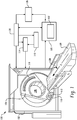
- FIGURE 1 illustrates a computed tomography (CT) scanner 100 that includes a stationary gantry 102 and a rotating gantry 104, which is rotatably supported by the stationary gantry 102.
- the rotating gantry 104 rotates around an examination region 106 about a longitudinal or z-axis 108.
- a radiation source 110 such as an x-ray tube, is supported by and rotates with the rotating gantry 104 around the examination region 106 and emits polychromatic radiation.
- a collimator 112 collimates the emitted radiation to produce a generally fan, wedge, or cone shaped radiation beam that traverses the examination region 106.
- a radiation sensitive detector array 118 detects photons that traverse the examination region 106 and generates projection data indicative the examination region.
- An injector 114 is configured to inject or administer a contrast medium in the patient for a scan.
- the injector is used to concurrently administer at least two different contrast agents (e.g., a contrast agent containing gadolinium or iodine, etc.) with two different spectral properties in a same vessel or in different vessels.
- the injector is used to successively administer two or more different contrast agents with a delay between the administering.
- a modulator 116 provides a control signal indicative of the injection pattern or profile of the two or more different contrast agents, including the concentrations of the two or more different contrast agents over time.
- the contrast agents can alternatively be manually administered by a clinician or the like.
- a reconstructor 120 reconstructs the projection data and generates volumetric image data indicative thereof.
- the reconstructor 120 employs a spectral algorithm 124 such as a K-edge algorithm.
- a spectral algorithm 124 such as a K-edge algorithm.
- Such an algorithm allows for selective and quantitative imaging of materials with different spectral properties, such as one or more administered contrast agents.
- the reconstructor 120 may also employ conventional reconstruction algorithms, for example, a filtered backprojection algorithm or an iterative reconstruction algorithm.
- An image generator 126 processes the volumetric image data and generates one or more images. In one instance, this includes generating at least a first image showing a first contrast agent and a second image showing a second contrast agent. If a tissue specific contrast agent(s) is used, the contrast is substantially absorbed by the tissue and the corresponding image(s) is indicative of the tissue. If a non-tissue specific contrast agent(s) is used, the corresponding image(s) is indicative of the vessels through which the contrast flows. One or more than one of the contrast agents can be specific or non-specific.
- the image generator 126 can also generate other images such as a conventional CT attenuation based image, another image showing another contrast agent, a Compton effect image, a photo-electric effect image, etc.
- a general purpose computing system 130 serves as an operator console. Software resident on the console 130 allows the operator to control the operation of the system 100 such as select imaging protocols including contrast agent based K-edge imaging protocols. As described in greater detail below, one such protocol includes concurrently modulating the administration of two or more different contrast agents during a scan to acquire information about organ perfusion, such as cerebral perfusion, with a time series of spectral CT scans. Another protocol includes successively administering different contrast agents, with a delay therebetween, and performing a scan to concurrently acquire information about different physiological phases in a single scan.
- the scanner 100 is used to determine a perfusion parameter such as mean transit time (MTT).
- MTT mean transit time
- this includes using a combination of concurrently modulating administration of contrast agents and a spectral scan, and determining the MTT based on the modulation technique, the contrast agents, and resulting image data.
- FIGURE 2 illustrates an MTT determiner 202 that determines an MTT based on an image(s) generated from the image data and the contrast agent concentrations derived from the modulation pattern or profile.
- example contrast agent modulation profiles are shown.
- the y-axis 302 represents the amount (e.g., milliliter per second (ml/sec), etc.) of the contrast agent administered and the x-axis 304 represents time.
- a first profile 306 shows an amount of a first contrast agent as a function of time
- a second profile 308 shows an amount of a second contrast agent as a function of time.
- the profiles 306 and 308 are both saw tooth in shape. In other embodiments, the profiles can be different and/or otherwise shape, such as sinusoidal or triangular. Furthermore, the profiles 306 and 308 are inversions of each other. Moreover, in this example the aggregate amount of both contrast agents over time is substantially constant as shown at 310. In other embodiments, the aggregate amount of the contrast agents may change over time.
- a transition time can be determined by determining the time difference between the time when a particular ratio of the concentrations is administered and a point in an image where the ratio of the concentrations is about the same as the particular ratio of concentrations.
- the measured ratio at a particular image point or destination can be mapped to the modulation function shown in FIGURE 3 to determine the corresponding start time of that concentration ratio, and the difference in time represents that transition time.
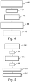
- At 402 at least two different contrast agents having two different spectral properties are concurrently administered to a subject during an imaging procedure, using pre-determined contrast agent administration modulation patterns.
- the subject is scanned.
- a spectral reconstruction is performed on the resulting projection data, which is indicative of the at least two different contrast agents.
- the concentrations of the at least two different contrast agents are determined for a particular image point based on the spectral reconstruction.
- the MTT determiner determines an MTT for the particular image point based on a ratio of the concentrations and the contrast modulation patterns.
- the scanner 100 is used for multi-phase study such as a multi-phase liver study.
- multi-phase studies can be used to identify hyper or hypo perfused regions (HCC or metastases) during the aortic phase, the portal venous phase and/or the equilibrium phase.
- HCC or metastases hyper or hypo perfused regions
- 3 to 5 scans may be performed after the contrast agent is injected in order to capture these phases.
- the number of scans may be reduced via a suitable injection protocol combined with a spectral CT separation of the injected contrast agents.
- a first contrast agent is administered for a first pre-set period of time.
- the first pre-set period of time is ten (10) seconds.
- the next administration of a contrast agent is delayed by a second pre-set period of time.
- the second pre-set period of time is ten (10) seconds.
- a second contrast agent is administered for a third pre-set period of time.
- the third pre-set period of time is five (5) seconds. If another contrast agent is to be administered, it may also be delayed another pre-set time period.
- scanning is delayed by a fourth pre-set period of time. In one instance, the fourth pre-set period of time is ten (10) seconds.
- a spectral CT scan is performed. Using the above protocol or other suitable protocol, during the scan the first contrast agent will be in the portal venous phase when the second contrast agent is in the aortic phase.
- the selective imaging capabilities of spectral CT allows the separation between the first and second contrast agents.
- two contrast images for two of the venous and the aortic are generated. As such, two contrast images for two of the phases can be captured in a single scan. When three or more contrast agents are administered, three or more images for the three phases are captured in a single scan.
- two or more contrast agents are concurrently administered in the same vessel or successively administered in the same vessel.
- administration of the contrast agents can alternatively be in different vessels.
- the contrast agents can be administered at different injection points (left and right hemisphere, front and back lobe, etc.).
- Another application of this technique is to solve the inverse problem of a complex pharmacokinetic model.
- the free parameter of a pharmacokinetic model can be numerically determined with a proper multi contrast agent modulated injection protocol and selective imaging of the used contrast agents.
- the reconstructor 120 can employ a K-edge algorithm.
- the following illustrates an example algorithm for two K-edge substances, such as the two contrast agents in the examples herein.
- the radiation source 110 emits polychromatic radiation with an emission spectrum T ( E ).
- Equation 1 includes the following add
- the input to the image generator 126 includes the energy-resolved detection signals d i for a plurality, e.g., four (4), energy bins.
- the emission spectrum T(E) and spectral sensitivity D i (E) generally are known.
- the absorption spectra P ( E ), C ( E ), K 1 ( E ) and K 2 ( E ) are known. Since the energy dependent functions and the detection signals d i are known and since at least four detection signals d 1 - d 4 are available for at least four energy bins b 1 - b 4 , a system of at least four equations is formed having four unknowns which can thus be solved with known mathematical methods. If more than four energy bins are available, it is preferred to use a maximum likelihood approach that takes the noise statistics of the measurements into account.
- the resulting density length products ⁇ k-edge1 and ⁇ k-edge2 are the first substance contribution and the second substance contribution, respectively, which can be used to generate a first K-edge image for the first substance and a second K-edge image for the second substance.
- the photo-electric density length product ⁇ photo can be used to reconstruct a photo-electric image
- the Compton effect density length product ⁇ compton can be used to reconstruct a Compton effect image.
- the Compton effect image and the photo-electric effect image show the object itself. These four images can be shown one by one, or they can be mixed, for example, a final image can show the first substance, the second substance and the Compton effect image and/or the photo-electric effect image. It is also possible to reconstruct one image showing one, some or all of the four components.
- the spectral decomposition can be performed on projection data or in the image domain.
- the embodiments can be used to determine other parameters related to perfursion such, but not limited to, blood flow, blood volume, and/or other perfusion parameters.
Claims (10)
- System, umfassend:eine Strahlungsquelle (110), konfiguriert, um um einen Untersuchungsbereich herum zu rotieren und polychromatische Strahlung zu emittieren, die den Untersuchungsbereich durchquert;ein Detektorarray (118) gegenüber der Strahlungsquelle (110), dem Untersuchungsbereich gegenüberliegend lokalisiert, konfiguriert, um Strahlung, die den Untersuchungsbereich durchquert, zu detektieren, und ein davon indikatives Signal zu erzeugen;einen Injektor (114), konfiguriert, um mindestens zwei unterschiedliche Kontrastmittel für eine Bildgebungsprozedur auf Basis eines Kontrastmittelmengenmodulationsprofils zu verabreichen; undeinen Rekonstruierer (120), konfiguriert, um das Signal spektral zu rekonstruieren, um erste Bilddaten des ersten Kontrastmittels und zweite Bilddaten des zweiten Kontrastmittels zu erzeugen;
dadurch gekennzeichnet, dass das System weiter umfasstein Bestimmungsgerät (202) der mittleren Transitzeitdauer, konfiguriert, um eine mittlere Transitzeitdauer auf Basis der ersten und zweiten Bilddaten und der ersten und zweiten aus dem Kontrastmittelmodulationsprofil abgeleiteten Kontrastmittelkonzentration zu bestimmen. - System nach Anspruch 1, wobei der Injektor (114) konfiguriert ist, um die mindestens zwei Kontrastmittel auf Basis unterschiedlicher Modulationsmuster gleichzeitig zu verabreichen.
- System nach Anspruch 2, wobei das Modulationsprofil eines ist von dreieckig, sägezahn- oder sinusförmig.
- System nach einem der Ansprüche 1 bis 3, wobei der Injektor konfiguriert ist, um eine Menge jedes Kontrastmittels bezüglich der Zeit im Wesentlichen kontinuierlich zu variieren.
- System nach einem der Ansprüche 1 bis 4, wobei der Injektor konfiguriert ist, um die mindestens zwei unterschiedlichen Kontrastmittel so zu verabreichen, dass eine Gesamtmenge der Kontrastmittel im Wesentlichen über die Zeit konstant ist.
- System nach einem der Ansprüche 1 bis 5, wobei die Modulationsprofile des ersten und zweiten Kontrastmittels invers proportional sind.
- System nach einem der Ansprüche 1 oder 2, wobei der Rekonstruierer (120) das Signal in Bestandteile zerlegt, einschließlich, aber nicht beschränkt auf, mindestens einen ersten K-Kantenbestandteil und einen zweiten K-Kantenbestandteil, und das erste Bild auf dem ersten K-Kantenbestandteil basiert ist und das zweite Bild auf dem zweiten K-Kantenbestandteil basiert ist.
- System nach einem der Ansprüche 1 bis 3, weiter einschließend einen Modulator (116), konfiguriert, um das Modulationsprofil zu bestimmen und bereitzustellen.
- System nach einem der Ansprüche 1 bis 8, wobei das Bestimmungsgerät (202) der mittleren Transitzeitdauer die mittlere Transitzeitdauer für einen besonderen Bildpunkt auf Basis eines Verhältnisses der Konzentrationen und der Kontrastmodulationsmuster bestimmt.
- System nach Anspruch 9, wobei die mittlere Transitzeitdauer relativ zu der Injektionszeit eine absolute Übergangszeitdauer ist.
Applications Claiming Priority (2)
| Application Number | Priority Date | Filing Date | Title |
|---|---|---|---|
| US8175208P | 2008-07-18 | 2008-07-18 | |
| PCT/IB2009/052672 WO2010007545A1 (en) | 2008-07-18 | 2009-06-22 | Spectral imaging |
Publications (2)
| Publication Number | Publication Date |
|---|---|
| EP2303125A1 EP2303125A1 (de) | 2011-04-06 |
| EP2303125B1 true EP2303125B1 (de) | 2019-10-30 |
Family
ID=40947944
Family Applications (1)
| Application Number | Title | Priority Date | Filing Date |
|---|---|---|---|
| EP09786439.1A Active EP2303125B1 (de) | 2008-07-18 | 2009-06-22 | Spektralabbildung |
Country Status (5)
| Country | Link |
|---|---|
| US (1) | US9055919B2 (de) |
| EP (1) | EP2303125B1 (de) |
| JP (1) | JP5539342B2 (de) |
| CN (1) | CN102098963B (de) |
| WO (1) | WO2010007545A1 (de) |
Families Citing this family (17)
| Publication number | Priority date | Publication date | Assignee | Title |
|---|---|---|---|---|
| WO2012046157A1 (en) * | 2010-10-05 | 2012-04-12 | Koninklijke Philips Electronics N.V. | Apparatus and method for locating magnetic particles |
| WO2012101537A1 (en) * | 2011-01-27 | 2012-08-02 | Koninklijke Philips Electronics N.V. | Spectral imaging |
| RU2014148345A (ru) * | 2012-05-02 | 2016-06-20 | Конинклейке Филипс Н.В. | Спектральная компьютерная томографическая (ст) визуализация визуализируемых гранул, выделяющих лекарственное средство |
| DE102012222714A1 (de) * | 2012-12-11 | 2014-06-12 | Siemens Aktiengesellschaft | Ermittlung eines Mehrfachenergie-Bildes |
| WO2015005485A1 (ja) | 2013-07-11 | 2015-01-15 | 株式会社 東芝 | X線ct装置、x線ctシステム及びインジェクター |
| KR101725099B1 (ko) * | 2014-12-05 | 2017-04-26 | 삼성전자주식회사 | 컴퓨터 단층 촬영장치 및 그 제어방법 |
| CN107666861B (zh) * | 2015-03-18 | 2022-03-01 | 皇家飞利浦有限公司 | 在利用尺寸不同的药物洗脱微球珠粒进行经动脉化疗栓塞之后的药物浓度确定 |
| US10383590B2 (en) * | 2015-09-28 | 2019-08-20 | General Electric Company | Methods and systems for adaptive scan control |
| EP3373816B1 (de) * | 2015-11-10 | 2019-03-27 | Koninklijke Philips N.V. | Verfahren zur computertomografiebildgebung |
| CN107530037B (zh) * | 2015-12-17 | 2018-11-27 | 皇家飞利浦有限公司 | 用于生成对比剂浓度图的方法 |
| EP3481300A1 (de) * | 2016-07-06 | 2019-05-15 | Koninklijke Philips N.V. | System zur bereitstellung von bildern zur detektion von endolecks |
| DE102016222093A1 (de) * | 2016-11-10 | 2017-12-28 | Siemens Healthcare Gmbh | Simultaner Einsatz von unterschiedlichen Kontrastmitteln bei CT-Bildgebungsverfahren |
| CN106923856B (zh) * | 2017-04-14 | 2020-05-22 | 郑州大学第一附属医院 | 一种同时实现ct灌注与能谱肝脏扫描的影像处理方法 |
| CN114917492A (zh) * | 2017-08-23 | 2022-08-19 | 西门子医疗有限公司 | 提供适合于在对患者的辐照规划中使用的结果数据的方法 |
| US20190370956A1 (en) * | 2018-05-30 | 2019-12-05 | General Electric Company | Contrast imaging system and method |
| EP3795080B1 (de) * | 2019-09-19 | 2023-01-11 | Siemens Healthcare GmbH | Kontrastmittelbasierte zeitkodierung in der röntgenbildgebung |
| DE102020206729A1 (de) | 2020-05-28 | 2021-12-02 | Siemens Healthcare Gmbh | Bewegungskorrekturverfahren |
Family Cites Families (25)
| Publication number | Priority date | Publication date | Assignee | Title |
|---|---|---|---|---|
| US4859450A (en) * | 1984-08-13 | 1989-08-22 | The General Hospital Corporation | Method of NMR imaging using antibody to cardiac myosin |
| US6365183B1 (en) * | 1998-05-07 | 2002-04-02 | Alza Corporation | Method of fabricating a banded prolonged release active agent dosage form |
| EP1105162A1 (de) * | 1998-08-10 | 2001-06-13 | Bracco Research S.A. | Kombination eines positiven kernspinnresonenzkontrastmittels mit einem negativen kernspinnresonenzkontrastmittel |
| US6645147B1 (en) * | 1998-11-25 | 2003-11-11 | Acuson Corporation | Diagnostic medical ultrasound image and system for contrast agent imaging |
| DE19859811C2 (de) * | 1998-12-23 | 2001-05-10 | Hilekes Guido | Kontrastmittelinjektionssystem |
| WO2001008552A1 (en) * | 1999-08-03 | 2001-02-08 | Biophysica, Llc | Spectroscopic systems and methods for detecting tissue properties |
| US6804546B1 (en) * | 2001-04-20 | 2004-10-12 | Koninklijke Philips Electronics, N.V. | Multiple contrast echo-planar imaging for contrast-enhanced imaging |
| WO2002082113A2 (en) * | 2001-04-30 | 2002-10-17 | Medrad, Inc. | Improved mr injector system with increased mobility and electromagnetic interference mitigation |
| ATE404876T1 (de) * | 2001-11-12 | 2008-08-15 | Wisconsin Alumni Res Found | Dreidimensionale phasenkontrastmagnetresonanzabbildung mit verschachtelten projektions-rekonstruktions-daten |
| US6745066B1 (en) * | 2001-11-21 | 2004-06-01 | Koninklijke Philips Electronics, N.V. | Measurements with CT perfusion |
| US7627078B2 (en) * | 2002-11-08 | 2009-12-01 | Ge Medical Systems Global Technology Company, Llc | Methods and apparatus for detecting structural, perfusion, and functional abnormalities |
| US6813333B2 (en) * | 2002-11-27 | 2004-11-02 | Ge Medical Systems Global Technology Company, Llc | Methods and apparatus for detecting structural, perfusion, and functional abnormalities |
| US20040101088A1 (en) * | 2002-11-27 | 2004-05-27 | Sabol John Michael | Methods and apparatus for discriminating multiple contrast agents |
| WO2005009206A2 (en) * | 2003-06-25 | 2005-02-03 | Besson Guy M | Dynamic multi-spectral imaging system |
| ATE476724T1 (de) * | 2003-12-19 | 2010-08-15 | Koninkl Philips Electronics Nv | Verfahren zur computerunterstützten visualisierung diagnostischer bilddaten |
| EP1756742A2 (de) * | 2004-05-28 | 2007-02-28 | Philips Intellectual Property & Standards GmbH | System zur eingriffsfreien bestimmung der tracer-konzentration in blut |
| US20060036167A1 (en) * | 2004-07-03 | 2006-02-16 | Shina Systems Ltd. | Vascular image processing |
| US20080253503A1 (en) | 2005-09-22 | 2008-10-16 | Koninklijke Philips Electronics N. V. | Ct-Imaging System |
| US8208699B2 (en) * | 2005-10-05 | 2012-06-26 | Koninklijke Philips Electronics N.V. | Method and apparatus for predicting enhancement in angiography |
| DE102006009222B4 (de) * | 2006-02-28 | 2008-02-28 | Siemens Ag | Verfahren und Vorrichtung zur Bestimmung der Konzentration einer Substanz in einem Körpermaterial mittels Mehr-Energie-Computertomographie |
| AU2007244705A1 (en) * | 2006-04-27 | 2007-11-08 | Barnes-Jewish Hospital | Detection and imaging of target tissue |
| US7756239B2 (en) * | 2006-12-07 | 2010-07-13 | General Electric Company | Diagnostic imaging two non K-edge basis materials plus N K-edge contrast agents |
| HUE040477T2 (hu) * | 2006-12-29 | 2019-03-28 | Bayer Healthcare Llc | Betegalapú paramétergeneráló rendszerek gyógyászati injekciós eljárásokhoz |
| US20080208068A1 (en) * | 2007-02-26 | 2008-08-28 | Timothy Robertson | Dynamic positional information constrained heart model |
| US20090052621A1 (en) * | 2007-08-23 | 2009-02-26 | Deborah Joy Walter | Method and apparatus for basis material decomposition with k-edge materials |
-
2009
- 2009-06-22 JP JP2011518036A patent/JP5539342B2/ja active Active
- 2009-06-22 US US13/000,384 patent/US9055919B2/en active Active
- 2009-06-22 EP EP09786439.1A patent/EP2303125B1/de active Active
- 2009-06-22 CN CN200980127987.0A patent/CN102098963B/zh active Active
- 2009-06-22 WO PCT/IB2009/052672 patent/WO2010007545A1/en active Application Filing
Non-Patent Citations (1)
| Title |
|---|
| None * |
Also Published As
| Publication number | Publication date |
|---|---|
| JP5539342B2 (ja) | 2014-07-02 |
| CN102098963A (zh) | 2011-06-15 |
| US9055919B2 (en) | 2015-06-16 |
| WO2010007545A1 (en) | 2010-01-21 |
| CN102098963B (zh) | 2014-03-26 |
| JP2011528248A (ja) | 2011-11-17 |
| US20110097273A1 (en) | 2011-04-28 |
| EP2303125A1 (de) | 2011-04-06 |
Similar Documents
| Publication | Publication Date | Title |
|---|---|---|
| EP2303125B1 (de) | Spektralabbildung | |
| Lee et al. | Computed body tomography with MRI correlation | |
| Fleischmann et al. | Optimal vascular and parenchymal contrast enhancement: the current state of the art | |
| EP2429403B1 (de) | Perfusionsbildgebung | |
| Hartman et al. | Applications of dual-energy CT in urologic imaging: an update | |
| JP5363572B2 (ja) | スペクトルx線撮像システム及び方法 | |
| US9955934B2 (en) | Dynamic acquisition sampling rate for computed tomography perfusion (CTP) imaging | |
| Saini | Multi–detector row CT: principles and practice for abdominal applications | |
| Stehli et al. | Impact of monochromatic coronary computed tomography angiography from single-source dual-energy CT on coronary stenosis quantification | |
| Müller et al. | Interventional dual‐energy imaging—Feasibility of rapid kV‐switching on a C‐arm CT system | |
| Christensen et al. | Effects of iopamidol-370 versus iodixanol-320 on coronary contrast, branch depiction, and heart rate variability in dual-source coronary MDCT angiography | |
| JP5820549B2 (ja) | 灌流イメージング | |
| US11406339B2 (en) | System and method for determining vascular velocity using medical imaging | |
| WO2008078231A1 (en) | Imaging system for imaging substances present in an object of interest | |
| Knobloch et al. | Dual-energy computed tomography for the assessment of early treatment effects of regorafenib in a preclinical tumor model: comparison with dynamic contrast-enhanced CT and conventional contrast-enhanced single-energy CT | |
| Chatzizisis et al. | Accuracy and reproducibility of automated, standardized coronary transluminal attenuation gradient measurements | |
| Wu et al. | Left ventricular functional analysis using 64-slice multidetector row computed tomography: comparison with left ventriculography and cardiovascular magnetic resonance | |
| US20170014069A1 (en) | Spectral imaging based fluid volume map | |
| FI104042B (fi) | Menetelmä keuhkojen perfuusion mittaamiseksi | |
| EP2501287B1 (de) | Funktionelle bildgebung | |
| Taguchi | Imaging Technologies and Potential Clinical Applications of Photon Counting X-Ray Computed Tomography | |
| Territo et al. | Measurement of cardiovascular function using a novel view-sharing PET reconstruction method and tracer kinetic analysis | |
| Kang et al. | Evaluation of Myocardial Ischemia Using Perfusion Study | |
| Ko | CT Evaluation of the Myocardial Blood Supply: Dual-Source Dual-Energy CT | |
| Ko | Stress Myocardial Perfusion Imaging Using Computed Tomography in Stable Coronary Artery Disease |
Legal Events
| Date | Code | Title | Description |
|---|---|---|---|
| PUAI | Public reference made under article 153(3) epc to a published international application that has entered the european phase |
Free format text: ORIGINAL CODE: 0009012 |
|
| 17P | Request for examination filed |
Effective date: 20110218 |
|
| AK | Designated contracting states |
Kind code of ref document: A1 Designated state(s): AT BE BG CH CY CZ DE DK EE ES FI FR GB GR HR HU IE IS IT LI LT LU LV MC MK MT NL NO PL PT RO SE SI SK TR |
|
| AX | Request for extension of the european patent |
Extension state: AL BA RS |
|
| DAX | Request for extension of the european patent (deleted) | ||
| RAP1 | Party data changed (applicant data changed or rights of an application transferred) |
Owner name: KONINKLIJKE PHILIPS N.V. Owner name: PHILIPS INTELLECTUAL PROPERTY & STANDARDS GMBH |
|
| 17Q | First examination report despatched |
Effective date: 20140924 |
|
| STAA | Information on the status of an ep patent application or granted ep patent |
Free format text: STATUS: EXAMINATION IS IN PROGRESS |
|
| GRAP | Despatch of communication of intention to grant a patent |
Free format text: ORIGINAL CODE: EPIDOSNIGR1 |
|
| STAA | Information on the status of an ep patent application or granted ep patent |
Free format text: STATUS: GRANT OF PATENT IS INTENDED |
|
| RIC1 | Information provided on ipc code assigned before grant |
Ipc: A61M 5/00 20060101ALI20190425BHEP Ipc: A61K 49/00 20060101ALI20190425BHEP Ipc: A61B 5/00 20060101ALI20190425BHEP Ipc: A61B 6/00 20060101AFI20190425BHEP Ipc: A61B 6/03 20060101ALI20190425BHEP |
|
| INTG | Intention to grant announced |
Effective date: 20190515 |
|
| GRAS | Grant fee paid |
Free format text: ORIGINAL CODE: EPIDOSNIGR3 |
|
| GRAA | (expected) grant |
Free format text: ORIGINAL CODE: 0009210 |
|
| STAA | Information on the status of an ep patent application or granted ep patent |
Free format text: STATUS: THE PATENT HAS BEEN GRANTED |
|
| AK | Designated contracting states |
Kind code of ref document: B1 Designated state(s): AT BE BG CH CY CZ DE DK EE ES FI FR GB GR HR HU IE IS IT LI LT LU LV MC MK MT NL NO PL PT RO SE SI SK TR |
|
| REG | Reference to a national code |
Ref country code: GB Ref legal event code: FG4D |
|
| REG | Reference to a national code |
Ref country code: CH Ref legal event code: EP |
|
| REG | Reference to a national code |
Ref country code: AT Ref legal event code: REF Ref document number: 1195292 Country of ref document: AT Kind code of ref document: T Effective date: 20191115 |
|
| REG | Reference to a national code |
Ref country code: DE Ref legal event code: R096 Ref document number: 602009060297 Country of ref document: DE |
|
| REG | Reference to a national code |
Ref country code: IE Ref legal event code: FG4D |
|
| REG | Reference to a national code |
Ref country code: DE Ref legal event code: R084 Ref document number: 602009060297 Country of ref document: DE |
|
| REG | Reference to a national code |
Ref country code: GB Ref legal event code: 746 Effective date: 20200107 |
|
| REG | Reference to a national code |
Ref country code: LT Ref legal event code: MG4D |
|
| RAP2 | Party data changed (patent owner data changed or rights of a patent transferred) |
Owner name: PHILIPS INTELLECTUAL PROPERTY & STANDARDS GMBH Owner name: KONINKLIJKE PHILIPS N.V. |
|
| PG25 | Lapsed in a contracting state [announced via postgrant information from national office to epo] |
Ref country code: NO Free format text: LAPSE BECAUSE OF FAILURE TO SUBMIT A TRANSLATION OF THE DESCRIPTION OR TO PAY THE FEE WITHIN THE PRESCRIBED TIME-LIMIT Effective date: 20200130 Ref country code: LT Free format text: LAPSE BECAUSE OF FAILURE TO SUBMIT A TRANSLATION OF THE DESCRIPTION OR TO PAY THE FEE WITHIN THE PRESCRIBED TIME-LIMIT Effective date: 20191030 Ref country code: PL Free format text: LAPSE BECAUSE OF FAILURE TO SUBMIT A TRANSLATION OF THE DESCRIPTION OR TO PAY THE FEE WITHIN THE PRESCRIBED TIME-LIMIT Effective date: 20191030 Ref country code: GR Free format text: LAPSE BECAUSE OF FAILURE TO SUBMIT A TRANSLATION OF THE DESCRIPTION OR TO PAY THE FEE WITHIN THE PRESCRIBED TIME-LIMIT Effective date: 20200131 Ref country code: ES Free format text: LAPSE BECAUSE OF FAILURE TO SUBMIT A TRANSLATION OF THE DESCRIPTION OR TO PAY THE FEE WITHIN THE PRESCRIBED TIME-LIMIT Effective date: 20191030 Ref country code: NL Free format text: LAPSE BECAUSE OF FAILURE TO SUBMIT A TRANSLATION OF THE DESCRIPTION OR TO PAY THE FEE WITHIN THE PRESCRIBED TIME-LIMIT Effective date: 20191030 Ref country code: PT Free format text: LAPSE BECAUSE OF FAILURE TO SUBMIT A TRANSLATION OF THE DESCRIPTION OR TO PAY THE FEE WITHIN THE PRESCRIBED TIME-LIMIT Effective date: 20200302 Ref country code: LV Free format text: LAPSE BECAUSE OF FAILURE TO SUBMIT A TRANSLATION OF THE DESCRIPTION OR TO PAY THE FEE WITHIN THE PRESCRIBED TIME-LIMIT Effective date: 20191030 Ref country code: SE Free format text: LAPSE BECAUSE OF FAILURE TO SUBMIT A TRANSLATION OF THE DESCRIPTION OR TO PAY THE FEE WITHIN THE PRESCRIBED TIME-LIMIT Effective date: 20191030 Ref country code: FI Free format text: LAPSE BECAUSE OF FAILURE TO SUBMIT A TRANSLATION OF THE DESCRIPTION OR TO PAY THE FEE WITHIN THE PRESCRIBED TIME-LIMIT Effective date: 20191030 Ref country code: BG Free format text: LAPSE BECAUSE OF FAILURE TO SUBMIT A TRANSLATION OF THE DESCRIPTION OR TO PAY THE FEE WITHIN THE PRESCRIBED TIME-LIMIT Effective date: 20200130 |
|
| REG | Reference to a national code |
Ref country code: NL Ref legal event code: MP Effective date: 20191030 |
|
| PG25 | Lapsed in a contracting state [announced via postgrant information from national office to epo] |
Ref country code: IS Free format text: LAPSE BECAUSE OF FAILURE TO SUBMIT A TRANSLATION OF THE DESCRIPTION OR TO PAY THE FEE WITHIN THE PRESCRIBED TIME-LIMIT Effective date: 20200229 Ref country code: HR Free format text: LAPSE BECAUSE OF FAILURE TO SUBMIT A TRANSLATION OF THE DESCRIPTION OR TO PAY THE FEE WITHIN THE PRESCRIBED TIME-LIMIT Effective date: 20191030 |
|
| PG25 | Lapsed in a contracting state [announced via postgrant information from national office to epo] |
Ref country code: CZ Free format text: LAPSE BECAUSE OF FAILURE TO SUBMIT A TRANSLATION OF THE DESCRIPTION OR TO PAY THE FEE WITHIN THE PRESCRIBED TIME-LIMIT Effective date: 20191030 Ref country code: DK Free format text: LAPSE BECAUSE OF FAILURE TO SUBMIT A TRANSLATION OF THE DESCRIPTION OR TO PAY THE FEE WITHIN THE PRESCRIBED TIME-LIMIT Effective date: 20191030 Ref country code: RO Free format text: LAPSE BECAUSE OF FAILURE TO SUBMIT A TRANSLATION OF THE DESCRIPTION OR TO PAY THE FEE WITHIN THE PRESCRIBED TIME-LIMIT Effective date: 20191030 Ref country code: EE Free format text: LAPSE BECAUSE OF FAILURE TO SUBMIT A TRANSLATION OF THE DESCRIPTION OR TO PAY THE FEE WITHIN THE PRESCRIBED TIME-LIMIT Effective date: 20191030 |
|
| REG | Reference to a national code |
Ref country code: DE Ref legal event code: R097 Ref document number: 602009060297 Country of ref document: DE |
|
| REG | Reference to a national code |
Ref country code: AT Ref legal event code: MK05 Ref document number: 1195292 Country of ref document: AT Kind code of ref document: T Effective date: 20191030 |
|
| PG25 | Lapsed in a contracting state [announced via postgrant information from national office to epo] |
Ref country code: SK Free format text: LAPSE BECAUSE OF FAILURE TO SUBMIT A TRANSLATION OF THE DESCRIPTION OR TO PAY THE FEE WITHIN THE PRESCRIBED TIME-LIMIT Effective date: 20191030 Ref country code: IT Free format text: LAPSE BECAUSE OF FAILURE TO SUBMIT A TRANSLATION OF THE DESCRIPTION OR TO PAY THE FEE WITHIN THE PRESCRIBED TIME-LIMIT Effective date: 20191030 |
|
| PLBE | No opposition filed within time limit |
Free format text: ORIGINAL CODE: 0009261 |
|
| STAA | Information on the status of an ep patent application or granted ep patent |
Free format text: STATUS: NO OPPOSITION FILED WITHIN TIME LIMIT |
|
| 26N | No opposition filed |
Effective date: 20200731 |
|
| PG25 | Lapsed in a contracting state [announced via postgrant information from national office to epo] |
Ref country code: AT Free format text: LAPSE BECAUSE OF FAILURE TO SUBMIT A TRANSLATION OF THE DESCRIPTION OR TO PAY THE FEE WITHIN THE PRESCRIBED TIME-LIMIT Effective date: 20191030 Ref country code: SI Free format text: LAPSE BECAUSE OF FAILURE TO SUBMIT A TRANSLATION OF THE DESCRIPTION OR TO PAY THE FEE WITHIN THE PRESCRIBED TIME-LIMIT Effective date: 20191030 |
|
| REG | Reference to a national code |
Ref country code: DE Ref legal event code: R081 Ref document number: 602009060297 Country of ref document: DE Owner name: PHILIPS GMBH, DE Free format text: FORMER OWNER: PHILIPS INTELLECTUAL PROPERTY & STANDARDS GMBH, 20099 HAMBURG, DE |
|
| PG25 | Lapsed in a contracting state [announced via postgrant information from national office to epo] |
Ref country code: MC Free format text: LAPSE BECAUSE OF FAILURE TO SUBMIT A TRANSLATION OF THE DESCRIPTION OR TO PAY THE FEE WITHIN THE PRESCRIBED TIME-LIMIT Effective date: 20191030 |
|
| REG | Reference to a national code |
Ref country code: CH Ref legal event code: PL |
|
| PG25 | Lapsed in a contracting state [announced via postgrant information from national office to epo] |
Ref country code: LU Free format text: LAPSE BECAUSE OF NON-PAYMENT OF DUE FEES Effective date: 20200622 |
|
| REG | Reference to a national code |
Ref country code: BE Ref legal event code: MM Effective date: 20200630 |
|
| PG25 | Lapsed in a contracting state [announced via postgrant information from national office to epo] |
Ref country code: LI Free format text: LAPSE BECAUSE OF NON-PAYMENT OF DUE FEES Effective date: 20200630 Ref country code: IE Free format text: LAPSE BECAUSE OF NON-PAYMENT OF DUE FEES Effective date: 20200622 Ref country code: CH Free format text: LAPSE BECAUSE OF NON-PAYMENT OF DUE FEES Effective date: 20200630 |
|
| PG25 | Lapsed in a contracting state [announced via postgrant information from national office to epo] |
Ref country code: BE Free format text: LAPSE BECAUSE OF NON-PAYMENT OF DUE FEES Effective date: 20200630 |
|
| PG25 | Lapsed in a contracting state [announced via postgrant information from national office to epo] |
Ref country code: TR Free format text: LAPSE BECAUSE OF FAILURE TO SUBMIT A TRANSLATION OF THE DESCRIPTION OR TO PAY THE FEE WITHIN THE PRESCRIBED TIME-LIMIT Effective date: 20191030 Ref country code: MT Free format text: LAPSE BECAUSE OF FAILURE TO SUBMIT A TRANSLATION OF THE DESCRIPTION OR TO PAY THE FEE WITHIN THE PRESCRIBED TIME-LIMIT Effective date: 20191030 Ref country code: CY Free format text: LAPSE BECAUSE OF FAILURE TO SUBMIT A TRANSLATION OF THE DESCRIPTION OR TO PAY THE FEE WITHIN THE PRESCRIBED TIME-LIMIT Effective date: 20191030 |
|
| PG25 | Lapsed in a contracting state [announced via postgrant information from national office to epo] |
Ref country code: MK Free format text: LAPSE BECAUSE OF FAILURE TO SUBMIT A TRANSLATION OF THE DESCRIPTION OR TO PAY THE FEE WITHIN THE PRESCRIBED TIME-LIMIT Effective date: 20191030 |
|
| PGFP | Annual fee paid to national office [announced via postgrant information from national office to epo] |
Ref country code: FR Payment date: 20230622 Year of fee payment: 15 Ref country code: DE Payment date: 20230627 Year of fee payment: 15 |
|
| PGFP | Annual fee paid to national office [announced via postgrant information from national office to epo] |
Ref country code: GB Payment date: 20230620 Year of fee payment: 15 |