EP2302116B1 - Method for creating a sample warp and sample warper - Google Patents
Method for creating a sample warp and sample warper Download PDFInfo
- Publication number
- EP2302116B1 EP2302116B1 EP09012301A EP09012301A EP2302116B1 EP 2302116 B1 EP2302116 B1 EP 2302116B1 EP 09012301 A EP09012301 A EP 09012301A EP 09012301 A EP09012301 A EP 09012301A EP 2302116 B1 EP2302116 B1 EP 2302116B1
- Authority
- EP
- European Patent Office
- Prior art keywords
- thread
- warping drum
- warping
- transport belts
- measuring device
- Prior art date
- Legal status (The legal status is an assumption and is not a legal conclusion. Google has not performed a legal analysis and makes no representation as to the accuracy of the status listed.)
- Active
Links
- 238000000034 method Methods 0.000 title claims abstract description 16
- 230000008021 deposition Effects 0.000 claims description 3
- 238000005259 measurement Methods 0.000 abstract description 4
- 230000006870 function Effects 0.000 description 7
- 238000004804 winding Methods 0.000 description 7
- 230000002093 peripheral effect Effects 0.000 description 5
- 235000014676 Phragmites communis Nutrition 0.000 description 3
- 238000000429 assembly Methods 0.000 description 3
- 230000000712 assembly Effects 0.000 description 3
- 238000000151 deposition Methods 0.000 description 2
- 238000004519 manufacturing process Methods 0.000 description 2
- 238000012544 monitoring process Methods 0.000 description 2
- 238000013459 approach Methods 0.000 description 1
- 230000009286 beneficial effect Effects 0.000 description 1
- 238000010276 construction Methods 0.000 description 1
- 238000012937 correction Methods 0.000 description 1
- 238000011161 development Methods 0.000 description 1
- 230000002996 emotional effect Effects 0.000 description 1
- 238000009499 grossing Methods 0.000 description 1
- 238000009940 knitting Methods 0.000 description 1
- 238000012545 processing Methods 0.000 description 1
- 230000004044 response Effects 0.000 description 1
- 238000009941 weaving Methods 0.000 description 1
Images
Classifications
-
- D—TEXTILES; PAPER
- D02—YARNS; MECHANICAL FINISHING OF YARNS OR ROPES; WARPING OR BEAMING
- D02H—WARPING, BEAMING OR LEASING
- D02H3/00—Warping machines
- D02H3/04—Sample warpers
Definitions
- the invention relates to a method for producing a pattern chain, in which one stores threads using thread guides on conveyor belts which are arranged on the circumference of a warping drum, seen from the front side of the warping drum form a polygon and are axially parallel to the warping drum movable, and a thread application produced, wherein the yarn guide and the conveyor belts during deposition moves relative to each other.
- the invention relates to a sample warping machine with a warping drum, at the periphery of which a plurality of parallel to the axis of the warping drum movable conveyor belts are arranged, which form seen from the front side of the warping drum form a polygon, and a plurality of yarn guides, with the help of threads on the conveyor belts to form a Thread order can be stored, the thread guide and the conveyor belts are parallel to the axis of the warping drum relative to each other movable.
- Such a method and such a sample warper are for example EP 1 479 804 A2 known.
- Other sample warping machines are out EP 1 930 489 A1 and DE 44 46 279 C1 known.
- Another such method and another such sample warper are, for example EP 1 445 361 A2 known.
- a pattern chain which can also be referred to as a "short chain" is produced by winding one or more threads simultaneously from one end face of the warping drum around the circumference of the warping drum and thereby onto transport surfaces, which are designed, for example, as endless, circulating conveyor belts drops.
- transport surfaces which are designed, for example, as endless, circulating conveyor belts drops.
- EP 1 460 156 A2 Another type of warping machines, called cone chillers, is out EP 1 460 156 A2 known.
- a cylindrical warping drum is provided which has a cone-shaped end portion.
- Several threads are drawn parallel to each other and at the same time from a stationary gate and wound around the circumference of the warping drum by the warping drum rotates.
- the threads are passed through a reed with a plurality of lanes, whereby a single thread can be passed through each lane.
- the reed is displaced parallel to the axis of the warping drum towards the cone as the warping drum rotates.
- a measuring device which is connected to the drive for the Riet, determines the parallelism of the surface of the forming coil.
- DE 43 04 956 A1 shows a similar cone warping machine in which characteristics are recorded in the production of a first coil, which characterize the shape of the coil. When skinning subsequent reels are respectively recorded at the same number of revolutions of the warping drum, the characteristics and compared with the characteristics of the first coil. If there is a deviation, the thread tension of the fed sequential tape is corrected.
- the invention has for its object to produce a pattern chain with high quality.
- This object is achieved in a method of the type mentioned above by determining at least one parameter of the thread application on at least one conveyor belt and controls the relative movement between the thread guides and the conveyor belts in dependence on the determined parameter, wherein as a parameter the height of the thread order and / or the parallelism of the surface of the thread application with the axis of the warping drum and / or the slope of the free end face of the thread application used.
- At least one of the following subassemblies is controlled in order to generate the relative movement: thread guide, laying unit, on which the thread guides are movably arranged, conveyor belts and warping drum. You can also move several of these modules controlled simultaneously to achieve the desired structure of the thread order. In principle, however, it is sufficient to move one of these assemblies in order to produce the thread application with a conically bevelled end face and an axis-parallel peripheral surface.
- the warping drum is rotated when depositing the threads and limits the determination of the parameter to predetermined rotational positions of the warping drum. If you limit the determination of the parameter on the rotational positions of the warping drum, in which a conveyor belt is below a measuring device, then you can determine the parameter exactly on the conveyor belts. This is sufficient in most cases to gain enough information about the structure of the thread order, so that you can control the relative movements in a row.
- conveyor belts are used, to which a wedge-shaped contact surface with a predetermined pitch angle is assigned at one end of a working area.
- This pitch angle corresponds to the slope of the cone at the other axial end of the thread application.
- a measuring device which has at least one parameter of the thread application on at least one conveyor belt determined and which is connected to a drive control, which controls the relative movement between the yarn guides and the conveyor belts in dependence on the determined parameter, the measuring device determines at least one of the following parameters: height of the thread order, parallelism of the surface of the thread application with the axis of the warping drum and slope of the free end of the thread application.
- Such relative movement is usually present during winding to produce the cone-like structure at an end face of the thread application. If the thread application does not meet the desired specifications, then the relative movement is made larger or smaller. For example, if the surface of the thread application is not parallel to the axis of the warping drum, then the relative movement between the thread guides and the conveyor belts is too large or too small and must be corrected accordingly. The same applies if the slope of the free end of the thread order does not meet the desired specification.
- the conveyor belts at one end of a work area is assigned a wedge-shaped contact surface with a predetermined pitch angle.
- This pitch angle corresponds to the cone angle at the other end of the thread application.
- the abutment surface may be arranged on a wedge-shaped element which is fastened directly to the respective conveyor belt. But it is also possible to arrange the wedge-shaped contact surface on a separate movable from the conveyor belts device and then move this device together when creating the thread application with the conveyor belts.
- At least one of the following subassemblies is movable to produce the relative movement: thread guide, laying unit, on which the thread guides are movably arranged, conveyor belts and warping drum. You can also move several of these assemblies at the same time. However, the control is simplified if only one of these modules is moved at the same time. You can then use the mobility of the other modules for other functions.
- the measuring device is designed as a laser measuring device.
- a laser measuring device can be used here as a distance measuring device to determine the height of the thread application, the parallelism of the surface at the periphery of the thread application with the axis of the warping drum and / or the slope of the free end of the thread application.
- a laser measuring device has a relatively high resolution or accuracy of 30 ⁇ m. This is sufficient for most of the commonly used threads.
- the warping drum on a rotary drive and an angle sensor, wherein the angle encoder is connected to the measuring device.
- the angle encoder thus "clocks" the measuring device, ie it tells the measuring device, when the warping drum in Rotation angle positions is where a parameter can be determined.
- a measuring device that detects a distance to a fixed point would then continuously determine other measured values as the warping drum rotates. Of course you can also correct these changing measured values or move the measuring device accordingly. It is easier, however, if one makes a measurement only at predetermined circumferential points of the warping drum.
- the measuring device is displaceable parallel to the axis of the warping drum. You can then control wider bands, for example, include 24 or 48 adjacent threads. The measuring device can then be moved periodically back and forth, for example, to monitor the structure of the thread application.
- a memory device in which a relative movement function can be stored, wherein the memory device is connected to the drive control.
- the memory device is connected to the drive control.
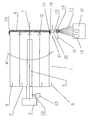
- the figure shows a very schematic representation of a sample warping machine 1 with a warping drum 2, which has a rotary drive 3. With the aid of the rotary drive 3, the warping drum 2 is rotated in the direction of an arrow 4 when generating a pattern chain.
- a plurality of conveyor belts 5 are arranged, which are movable in the direction of an arrow 6 by a drive, not shown.
- the conveyor belts 5 thus form transport surfaces which are movable parallel to the axis 7 of the warping drum 2, namely when generating the pattern chain from a free end 8 to the end 9, on which the rotary drive is arranged.
- Each conveyor belt 5 is assigned a wedge-shaped contact surface 10.
- the wedge-shaped bearing surface 10 is attached directly to the conveyor belt 5 and is characterized together with the conveyor belt. 5 emotional. But you can also arrange the contact surfaces 10 separately from the conveyor belts 5 and move in other ways together with the conveyor belts 5.
- the abutment surfaces 10 are located adjacent the free end 8, i. the conveyor belts 5 have been moved accordingly before the beginning of the winding.
- the threads 11 are guided by a laying unit 14.
- a schematically illustrated thread guide 15 is provided for each thread.
- Each yarn guide 15 may be movable parallel to the axis 7 of the warping drum 2 relative to the laying unit 14.
- the laying unit 14 may be movable in total parallel to the axis 7 of the warping drum 2.
- the conveyor belts 5 are also movable and driven. They are moved so that their outer surface, i. the radially outer strand moves from the free end 8 to the other end 9. Finally, it is also provided that the warping drum 2 is displaceable in total parallel to its axis 7.
- a thread application 17 is to be generated, which has a cone-shaped end face 18 whose inclination the slope of the contact surface 10 matches.
- an outer circumferential surface 19 of the thread application 17 is arranged parallel to the axis 7 of the warping drum 2.
- the measuring device 20 is parallel to the axis of the warping drum 2 displaced, as indicated by the double arrow 21.
- the measuring device 20 determines a distance between the peripheral surface 19 of the thread application 17 and a fixed point. With the aid of the measuring device 20, it is thus possible to determine the layer thickness increase of the thread application 17. With this layer thickness increase, which results from a sequence of measurements of the thickness or the height of the thread application, one can determine the size of the relative movement between the thread guides 15 and the conveyor belts 5, which is necessary for the just-wound ribbon, so the entirety of the simultaneously wound threads 11, the angle of the contact surface 10 follows.
- this angle can be calculated in advance. Such a determination is advantageously taken even before the beginning of the warping process, so that the first or a few turns at the beginning of the warping process with these calculated values of the "feed”, ie the relative movement between the yarn guides 15 and the conveyor belts 5, is driven. Now, it is determined with the aid of the measuring device 20, whether the set feed causes the individual turns of the ribbon so superimposed that their "front", ie the rotary drive 3 side facing abuts the contact surface 10 and thus on the other end side 18 of the desired cone angle results. If this is the case, then you can continue working with the set relative movement. If this is not the case then the relative movement has to be changed. To simplify the following explanation, the relative movement is referred to as "feed”. So if the cone angle at the end face 18 of the thread application 17 is too steep, then the feed must be increased. If it is too flat, then the feed must be reduced.
- the circumferential surface 19 of the thread application runs parallel to the axis 7 of the warping drum 2. If one notes that the peripheral surface 19 has a slope towards the end 9, then the feed must be reduced. If a slope is towards the end 9, then the feed must be increased.
- Another possibility is to monitor the inclination of the end face 18. If this inclination deviates from the inclination of the contact surface 10, then so is Here a corresponding correction of the feed required.
- the relative movement can be generated in various ways. In the simplest case, only one assembly is ever moved. The other assemblies are held stationary in the direction of the axis 7 of the warping drum 2.
- the drive control required for this purpose is not shown for reasons of clarity.
- the conveyor belts 5 form a polygon seen from the front side of the warping drum 2 ago. Accordingly, the thread application 17 will also form a polygon. If now the warping drum 2 is rotated by the rotary drive 3 during warping, then the distance between the measuring device 20 and the surface 19 changes solely due to the polygonal structure of the thread application 17.
- the warping drum 2 has an angle transmitter 22, which cooperates with an angle sensor 23. Accordingly, a non-illustrated drive control "knows" when the thread application 17 is supported by a conveyor belt 5 when passing by the measuring device 20. The measuring device 20 then only records measured values, for example, when a conveyor belt 5 passes under it.
Abstract
Description
Die Erfindung betrifft ein Verfahren zum Erzeugen einer Musterkette, bei dem man Fäden mit Hilfe von Fadenführern auf Transportbänder ablegt, die am Umfang einer Schärtrommel angeordnet sind, von der Stirnseite der Schärtrommel her gesehen ein Polygon bilden und achsparallel zur Schärtrommel bewegbar sind, und einen Fadenauftrag erzeugt, wobei man die Fadenführer und die Transportbänder während des Ablegens relativ zueinander bewegt.The invention relates to a method for producing a pattern chain, in which one stores threads using thread guides on conveyor belts which are arranged on the circumference of a warping drum, seen from the front side of the warping drum form a polygon and are axially parallel to the warping drum movable, and a thread application produced, wherein the yarn guide and the conveyor belts during deposition moves relative to each other.
Ferner betrifft die Erfindung eine Musterkettenschärmaschine mit einer Schärtrommel, an deren Umfang mehrere parallel zur Achse der Schärtrommel bewegbare Transportbänder angeordnet sind, die von der Stirnseite der Schärtrommel her gesehen ein Polygon bilden, und mehreren Fadenführern, mit deren Hilfe Fäden auf den Transportbändern zur Bildung eines Fadenauftrags ablegbar sind, wobei die Fadenführer und die Transportbänder parallel zur Achse der Schärtrommel relativ zueinander bewegbar sind.Furthermore, the invention relates to a sample warping machine with a warping drum, at the periphery of which a plurality of parallel to the axis of the warping drum movable conveyor belts are arranged, which form seen from the front side of the warping drum form a polygon, and a plurality of yarn guides, with the help of threads on the conveyor belts to form a Thread order can be stored, the thread guide and the conveyor belts are parallel to the axis of the warping drum relative to each other movable.
Ein derartiges Verfahren und eine derartige Musterkettenschärmaschine sind beispielsweise aus
Ein weiteres derartiges Verfahren und eine weitere derartige Musterkettenschärmaschine sind beispielsweise aus
Eine Musterkette, die auch als "Kurzkette" bezeichnet werden kann, wird dadurch hergestellt, dass man von einer Stirnseite der Schärtrommel her einen oder mehrere Fäden gleichzeitig um den Umfang der Schärtrommel wickelt und dabei auf Transportflächen, die beispielsweise als endlose, umlaufende Transportbänder ausgebildet sind, ablegt. Wenn der eine oder die mehreren gleichzeitig gewickelten Fäden mit der benötigten Anzahl von Windungen auf die Schärtrommel aufgewickelt worden sind, dann bewegen sich die Transportflächen von der Stirnseite weg, um Platz für die nachfolgenden Fäden zu schaffen.A pattern chain, which can also be referred to as a "short chain", is produced by winding one or more threads simultaneously from one end face of the warping drum around the circumference of the warping drum and thereby onto transport surfaces, which are designed, for example, as endless, circulating conveyor belts drops. When the one or more co-wound yarns having the required number of turns are wound onto the warper drum, the transport surfaces move away from the end face to make room for the subsequent yarns.
Beim Aufwickeln der Fäden auf die Schärtrommel kann man die einzelnen Windungen nicht in radialer Richtung übereinander anordnen. In diesem Fall besteht die Gefahr, dass die Fäden an der freien Stirnseite herunterfallen und von nachfolgenden Windungen überwickelt werden. Dies ergibt beim späteren Umbäumen, d.h. beim Abwickeln der Kette von der Schärtrommel, erhebliche Schwierigkeiten, die bis zum Reißen der Fäden führen können.When winding the threads on the warping drum you can not arrange the individual turns in the radial direction one above the other. In this case, there is a risk that the threads fall down on the free end side and are wound by subsequent turns. This results in later rebuilding, i. when unwinding the warp from the warping drum, there are significant difficulties that can result in the tearing of the yarns.
Man erzeugt daher beim Wickeln der Fäden auf die Schärtrommel einen Fadenauftrag mit einer konusförmigen Stirnseite. Die Steigung dieser Stirnseite ist so gewählt, dass ein Herunterrutschen der Fäden nicht mehr zu befürchten ist. Um diese konusförmige Stirnseite zu erzeugen, muss man die Fadenführer und die Transportflächen beim Wickeln relativ zueinander bewegen. Insbesondere dann, wenn man mehrere Fäden gleichzeitig auf die Schärtrommel aufwickelt, also sogenannte "Bändchen" erzeugt, ist es für das spätere Abwickeln von einer gewissen Bedeutung, dass die Bändchen einen Fadenauftrag mit einer Umfangsfläche bilden, die möglichst genau parallel zur Achse der Schärtrommel verläuft. Wird diese Bedingung nicht eingehalten, kann sich später eine Kette ergeben, bei der einzelne Fäden sehr unterschiedliche Spannungen aufweisen. Eine derartige Kette ist später schwer zu verarbeiten, beispielsweise in einer Weberei oder einer Wirkerei.Therefore, during the winding of the threads on the warping drum, a thread application is produced with a conical end face. The slope of this end face is chosen so that a slipping down of the threads is no longer to be feared. To this cone-shaped end face too produce, you have to move the yarn guide and the transport surfaces during winding relative to each other. Especially then, if you wound several threads simultaneously on the warping drum, so called "ribbon" generated, it is for the subsequent unwinding of some importance that the bands form a thread order with a peripheral surface that runs as closely as possible parallel to the axis of the warping drum. If this condition is not met, later a chain can result in which individual threads have very different tensions. Such a chain is later difficult to process, for example in a weaving or knitting.
Eine andere Art von Schärmaschinen, so genannte Konusschärmaschinen, ist aus
Eine weiter Konusschärmaschine ist aus
Der Erfindung liegt die Aufgabe zugrunde, eine Musterkette mit hoher Qualität zu erzeugen.The invention has for its object to produce a pattern chain with high quality.
Diese Aufgabe wird bei einem Verfahren der eingangs genannten Art dadurch gelöst, dass man mindestens einen Parameter des Fadenauftrags auf mindestens einem Transportband ermittelt und die Relativbewegung zwischen den Fadenführern und den Transportbändern in Abhängigkeit von dem ermittelten Parameter steuert, wobei man als Parameter die Höhe des Fadenauftrags und/oder die Parallelität der Oberfläche des Fadenauftrags mit der Achse der Schärtrommel und/oder die Steigung der freien Stirnseite des Fadenauftrags verwendet.This object is achieved in a method of the type mentioned above by determining at least one parameter of the thread application on at least one conveyor belt and controls the relative movement between the thread guides and the conveyor belts in dependence on the determined parameter, wherein as a parameter the height of the thread order and / or the parallelism of the surface of the thread application with the axis of the warping drum and / or the slope of the free end face of the thread application used.
Man kontrolliert also, in welcher Weise die Fäden auf der Schärtrommel abgelegt werden, und steuert in Abhängigkeit davon, ob der Fadenauftrag gewünschten Vorgaben entspricht oder nicht, die Relativbewegung zwischen den Fadenführern und den Transportbändern. Dadurch ist es in einem stärkeren Maße als bisher möglich, Einfluss auf den Aufbau des Fadenauftrags zu nehmen, und zwar dergestalt, dass die so auf dem Umfang der Schärtrommel erzeugte Musterkette später einfacher und mit höherer Qualität abgezogen werden kann. Vielfach wird es ausreichen, einen der Parameter zu verwenden. In bestimmten Fällen kann es jedoch günstig sein, auch zwei oder drei dieser Größen als Parameter zu verwenden. Wenn man beispielsweise feststellt, dass die Oberfläche des Fadenauftrags nicht mehr parallel zur Achse der Schärtrommel verläuft, dann muss man die Relativbewegung zwischen den Transportbändern und den Fadenführern so steuern, dass die Fadenführer weniger weit über die Transportbändern bewegt werden, wenn sich eine Steigung zum Ende der Schärtrommel hin ergibt, das den Fadenführern abgewandt ist, oder man muss die Fadenführer und die Transportbänder relativ zueinander in eine größere Überdeckung steuern, wenn sich eine umgekehrte Steigung der Umfangsfläche des Fadenauftrags ergibt. Eine andere Möglichkeit besteht darin, die Steigung der freien Stirnseite zu kontrollieren. Wenn diese Steigung "stimmt", dann ist im Allgemeinen davon auszugehen, dass auch der Aufbau des Fadenauftrags den Vorgaben entspricht. Aus der Ermittlung der Höhe des Fadenauftrags an aufeinander folgenden Zeitpunkten kann man den Zuwachs des Fadenauftrags bestimmen und die Relativbewegung entsprechend dem Zuwachs steuern.It controls so in which way the threads are stored on the warping drum, and controls depending on whether the thread order desired specifications or not, the relative movement between the thread guides and the conveyor belts. This makes it possible, to a greater extent than previously possible, to influence the structure of the thread application, in such a way that the so on the circumference of the warping drum generated pattern chain can be deducted later easier and with higher quality. In many cases it will be sufficient to use one of the parameters. In certain cases, however, it may be beneficial to use two or three of these quantities as parameters. For example, if one notes that the surface of the thread application is no longer parallel to the axis of the warping drum, then one must control the relative movement between the conveyor belts and the thread guides so that the thread guides are moved less far over the conveyor belts, if a slope to the end the warping drum out, which is facing away from the yarn guides, or you have to control the yarn guide and the conveyor belts relative to each other in a larger coverage when there is a reverse slope of the peripheral surface of the thread order. Another possibility is to control the slope of the free end face. If this slope is "correct", then it can generally be assumed that the structure of the thread application also meets the specifications. From the determination of the height of the thread application at successive times, one can determine the increment of the thread application and control the relative movement according to the increment.
Hierbei ist bevorzugt, dass man zum Erzeugen der Relativbewegung mindestens eine der folgenden Baugruppen gesteuert bewegt: Fadenführer, Verlegeeinheit, an der die Fadenführer bewegbar angeordnet sind, Transportbänder und Schärtrommel. Man kann auch mehrere dieser Baugruppen gleichzeitig gesteuert bewegen, um den gewünschten Aufbau des Fadenauftrags zu erreichen. Prinzipiell reicht aber aus, eine dieser Baugruppen zu bewegen, um den Fadenauftrag mit einer konisch abgeschrägten Stirnseite und einer achsparallelen Umfangsfläche zu erzeugen.It is preferred that at least one of the following subassemblies is controlled in order to generate the relative movement: thread guide, laying unit, on which the thread guides are movably arranged, conveyor belts and warping drum. You can also move several of these modules controlled simultaneously to achieve the desired structure of the thread order. In principle, however, it is sufficient to move one of these assemblies in order to produce the thread application with a conically bevelled end face and an axis-parallel peripheral surface.
Vorzugsweise dreht man die Schärtrommel beim Ablegen der Fäden und begrenzt die Ermittlung des Parameters auf vorbestimmte Drehstellungen der Schärtrommel. Wenn man die Ermittlung des Parameters auf die Drehstellungen der Schärtrommel begrenzt, in denen sich ein Transportband unter einer Messeinrichtung befindet, dann kann man den Parameter genau an den Transportbändern ermitteln. Dies reicht in den meisten Fällen aus, um genügend Informationen über den Aufbau des Fadenauftrags zu gewinnen, so dass man in Folge die Relativbewegungen steuern kann.Preferably, the warping drum is rotated when depositing the threads and limits the determination of the parameter to predetermined rotational positions of the warping drum. If you limit the determination of the parameter on the rotational positions of the warping drum, in which a conveyor belt is below a measuring device, then you can determine the parameter exactly on the conveyor belts. This is sufficient in most cases to gain enough information about the structure of the thread order, so that you can control the relative movements in a row.
Wenn man den Fadenauftrag durch eine Abfolge von nebeneinander angeordneten Bändchen erzeugt, ist es günstig, den Parameter nur beim ersten Bändchen zu ermitteln und eine beim ersten Bändchen verwendete Funktion der Relativbewegung bei allen nachfolgenden Bändchen zu verwenden. Bei einer Musterkettenschärmaschine kann man eine Musterkette nicht dadurch erzeugen, dass man alle in der Kette enthaltenen Fäden gleichzeitig nebeneinander aufwickelt. Man geht vielmehr so vor, dass man immer nur eine Gruppe von Fäden gleichzeitig wickelt. Diese nebeneinander gleichzeitig gewickelten Fäden werden auch als "Bändchen" bezeichnet. Insbesondere dann, wenn alle Bändchen gleichartig aufgebaut sind, kann es ausreichen, die Relativbewegungen zwischen den Fadenführern und den Transportbändern nur für das erste Bändchen zu ermitteln, indem man den Parameter überwacht und als Regelgröße verwendet. Man kann den Verlauf dieser Relativbewegung dann in einem Speicher ablegen und für den Aufbau nachfolgender Bändchen verwenden. Natürlich kann man auch während des Wickelns nachfolgender Bändchen noch eine Überprüfung vornehmen. Eine entsprechende Steuerung der Relativbewegung in Abhängigkeit von den aktuell gemessenen Parametern ist aber vielfach nicht mehr erforderlich. Dies spart Verarbeitungsleistung ein und ermöglicht insgesamt einen gleichmäßigen Aufbau der Kette.If you create the thread order through a sequence of juxtaposed ribbon, it is convenient to determine the parameter only at the first ribbon and to use a function used in the first band of relative movement in all subsequent ribbon. In a pattern warping machine, one can not create a pattern chain by simultaneously winding all the threads contained in the warp side by side. On the contrary, it is always possible to wrap only one group of threads at a time. These Threads wound simultaneously next to each other are also referred to as "ribbons". In particular, if all bands are constructed identically, it may be sufficient to determine the relative movements between the thread guides and the conveyor belts only for the first ribbon by monitoring the parameter and used as a controlled variable. You can then store the course of this relative movement in a memory and use for the construction of subsequent bands. Of course, you can also make a check during the wrapping of subsequent ribbons. However, a corresponding control of the relative movement as a function of the currently measured parameters is often no longer necessary. This saves processing power and allows a uniform overall structure of the chain.
Vorzugsweise verwendet man Transportbänder, denen an einem Ende eines Arbeitsbereichs eine keilförmige Anlagefläche mit einem vorbestimmten Steigungswinkel zugeordnet ist. Dieser Steigungswinkel entspricht der Steigung des Konus am anderen axialen Ende des Fadenauftrags. Man erhält dann gleich von Anfang an den gewünschten Aufbau des Fadenauftrags, d.h. die Ermittlung der Parameter zur Steuerung der Relativbewegungen zwischen den Fadenführern und den Transportbändern kann gleich von der ersten Windung an erfolgen.Preferably, conveyor belts are used, to which a wedge-shaped contact surface with a predetermined pitch angle is assigned at one end of a working area. This pitch angle corresponds to the slope of the cone at the other axial end of the thread application. From the beginning, one then obtains the desired structure of the thread application, i. the determination of the parameters for controlling the relative movements between the yarn guides and the conveyor belts can be done from the first turn on.
Die Aufgabe wird bei einer Musterkettenschärmaschine der eingangs genannten Art dadurch gelöst, dass eine Messeinrichtung vorgesehen ist, die mindestens einen Parameter des Fadenauftrags auf mindestens einem Transportband ermittelt und die mit einer Antriebssteuerung verbunden ist, die die Relativbewegung zwischen den Fadenführern und den Transportbändern in Abhängigkeit von dem ermittelten Parameter steuert, wobei die Messeinrichtung mindestens einen der folgenden Parameter ermittelt: Höhe des Fadenauftrags, Parallelität der Oberfläche des Fadenauftrags mit der Achse der Schärtrommel und Steigung der freien Stirnseite des Fadenauftrags. Wie oben im Zusammenhang mit dem Verfahren erläutert, ist es mit Hilfe der Messeinrichtung möglich, einen oder mehrere Parameter des Fadenauftrags zu ermitteln und so festzustellen, ob der Fadenauftrag in gewünschter Weise erzeugt wird. Wenn dies nicht der Fall ist, dann wird die Relativbewegung zwischen den Fadenführern und den Transportbändern geändert. Eine derartige Relativbewegung ist während des Wickelns üblicherweise vorhanden, um den konusartigen Aufbau an einer Stirnseite des Fadenauftrags zu erzeugen. Wenn der Fadenauftrag nicht den gewünschten Vorgaben entspricht, dann wird die Relativbewegung größer oder kleiner gemacht. Wenn beispielsweise die Oberfläche des Fadenauftrags nicht parallel mit der Achse der Schärtrommel verläuft, dann ist die Relativbewegung zwischen den Fadenführern und den Transportbändern zu groß oder zu klein und muss entsprechend korrigiert werden. Gleiches gilt, wenn die Steigung der freien Stirnseite des Fadenauftrags nicht der gewünschten Vorgabe entspricht.The object is achieved in a sample warping machine of the type mentioned above in that a measuring device is provided which has at least one parameter of the thread application on at least one conveyor belt determined and which is connected to a drive control, which controls the relative movement between the yarn guides and the conveyor belts in dependence on the determined parameter, the measuring device determines at least one of the following parameters: height of the thread order, parallelism of the surface of the thread application with the axis of the warping drum and slope of the free end of the thread application. As explained above in connection with the method, it is possible with the aid of the measuring device to determine one or more parameters of the thread application and thus to determine whether the thread application is produced in the desired manner. If this is not the case, then the relative movement between the thread guides and the conveyor belts is changed. Such relative movement is usually present during winding to produce the cone-like structure at an end face of the thread application. If the thread application does not meet the desired specifications, then the relative movement is made larger or smaller. For example, if the surface of the thread application is not parallel to the axis of the warping drum, then the relative movement between the thread guides and the conveyor belts is too large or too small and must be corrected accordingly. The same applies if the slope of the free end of the thread order does not meet the desired specification.
Vorzugsweise ist den Transportbänder an einem Ende eines Arbeitsbereichs eine keilförmige Anlagefläche mit einem vorbestimmten Steigungswinkel zugeordnet. Dieser Steigungswinkel entspricht dem Konuswinkel an der anderen Stirnseite des Fadenauftrags. Die Anlagefläche kann an einem keilförmigen Element angeordnet sein, das unmittelbar an der jeweiligen Transportband befestigt ist. Es ist aber auch möglich, die keilförmige Anlagefläche an einer getrennt von den Transportbändern bewegbaren Einrichtung anzuordnen und diese Einrichtung dann gemeinsam beim Erzeugen des Fadenauftrags mit den Transportbändern zu verlagern.Preferably, the conveyor belts at one end of a work area is assigned a wedge-shaped contact surface with a predetermined pitch angle. This pitch angle corresponds to the cone angle at the other end of the thread application. The abutment surface may be arranged on a wedge-shaped element which is fastened directly to the respective conveyor belt. But it is also possible to arrange the wedge-shaped contact surface on a separate movable from the conveyor belts device and then move this device together when creating the thread application with the conveyor belts.
Vorzugsweise ist zur Erzeugung der Relativbewegung mindestens eine der folgenden Baugruppen bewegbar: Fadenführer, Verlegeeinheit, an der die Fadenführer bewegbar angeordnet sind, Transportbänder und Schärtrommel. Man kann auch mehrere dieser Baugruppen gleichzeitig bewegen. Die Steuerung vereinfacht sich jedoch, wenn gleichzeitig immer nur eine dieser Baugruppen bewegt wird. Man kann die Bewegbarkeit der anderen Baugruppen dann für andere Funktionen nutzen.Preferably, at least one of the following subassemblies is movable to produce the relative movement: thread guide, laying unit, on which the thread guides are movably arranged, conveyor belts and warping drum. You can also move several of these assemblies at the same time. However, the control is simplified if only one of these modules is moved at the same time. You can then use the mobility of the other modules for other functions.
Bevorzugterweise ist die Messeinrichtung als Laser-Messeinrichtung ausgebildet. Eine Laser-Messeinrichtung kann hier als Entfernungsmesseinrichtung eingesetzt werden, um die Höhe des Fadenauftrags, die Parallelität der Oberfläche am Umfang des Fadenauftrags mit der Achse der Schärtrommel und/oder die Steigung des freien Endes des Fadenauftrags zu ermitteln. Eine Laser-Messeinrichtung hat eine relativ hohe Auflösung oder Genauigkeit von 30 um. Dies reicht für die meisten der üblicherweise verwendeten Fäden aus.Preferably, the measuring device is designed as a laser measuring device. A laser measuring device can be used here as a distance measuring device to determine the height of the thread application, the parallelism of the surface at the periphery of the thread application with the axis of the warping drum and / or the slope of the free end of the thread application. A laser measuring device has a relatively high resolution or accuracy of 30 μm. This is sufficient for most of the commonly used threads.
Bevorzugterweise weist die Schärtrommel einen Rotationsantrieb und einen Winkelgeber auf, wobei der Winkelgeber mit der Messeinrichtung verbunden ist. Der Winkelgeber "taktet" also die Messeinrichtung, d.h. er teilt der Messeinrichtung mit, wann die Schärtrommel in Drehwinkelpositionen ist, in denen ein Parameter ermittelt werden kann. Eine Messeinrichtung, die eine Entfernung zu einem Fixpunkt ermittelt, würde dann laufend andere Messwerte ermitteln, wenn sich die Schärtrommel dreht. Natürlich kann man diese sich ändernden Messwerte auch rechnerisch korrigieren oder die Messeinrichtung entsprechend bewegen. Einfacher ist es jedoch, wenn man eine Messung nur an vorbestimmten Umfangspunkten der Schärtrommel vornimmt.Preferably, the warping drum on a rotary drive and an angle sensor, wherein the angle encoder is connected to the measuring device. The angle encoder thus "clocks" the measuring device, ie it tells the measuring device, when the warping drum in Rotation angle positions is where a parameter can be determined. A measuring device that detects a distance to a fixed point would then continuously determine other measured values as the warping drum rotates. Of course you can also correct these changing measured values or move the measuring device accordingly. It is easier, however, if one makes a measurement only at predetermined circumferential points of the warping drum.
Bevorzugterweise ist die Messeinrichtung parallel zur Achse der Schärtrommel verlagerbar. Man kann dann auch breitere Bändchen kontrollieren, die beispielsweise 24 oder 48 nebeneinanderliegende Fäden umfassen. Die Messeinrichtung kann dann beispielsweise periodisch hin und her bewegt werden, um den Aufbau des Fadenauftrags zu überwachen.Preferably, the measuring device is displaceable parallel to the axis of the warping drum. You can then control wider bands, for example, include 24 or 48 adjacent threads. The measuring device can then be moved periodically back and forth, for example, to monitor the structure of the thread application.
Bevorzugterweise ist eine Speichereinrichtung vorgesehen, in der eine Relativbewegungsfunktion speicherbar ist, wobei die Speichereinrichtung mit der Antriebssteuerung verbunden ist. Wie oben im Zusammenhang mit dem Verfahren erläutert, reicht es in vielen Fällen aus, die Funktion der Relativbewegungen, d.h. den zeitlichen Verlauf der Relativbewegung, beim ersten gewickelten Bändchen aufzuzeichnen und dann für alle nachfolgenden Bändchen zu verwenden. Dies ergibt dann einen Fadenauftrag mit einer sehr hohen Gleichmäßigkeit. Darüber hinaus ist es bei dieser Vorgehensweise möglich, die Funktion der Relativbewegung zu glätten, so dass der oder die Antriebe, die die Relativbewegung bewirken, gleichförmiger arbeiten können. Dadurch wird eine erhöhte Wärmeentwicklung vermieden.Preferably, a memory device is provided, in which a relative movement function can be stored, wherein the memory device is connected to the drive control. As explained above in connection with the method, it is sufficient in many cases to record the function of the relative movements, ie the time profile of the relative movement, in the first wound ribbon and then to use it for all subsequent bands. This then results in a thread application with a very high uniformity. About that In addition, with this approach, it is possible to smooth the function of the relative movement, so that the one or more drives, which cause the relative movement, can work more uniformly. As a result, an increased heat development is avoided.
Die Erfindung wird im Folgenden anhand eines bevorzugten Ausführungsbeispiels in Verbindung mit der Zeichnung beschrieben. Hierin zeigt die
- einzige Figur:
- eine schematische Darstellung zur Er- läuterung der Erzeugung einer Muster- kette.
- only figure
- a schematic representation for the explanation of the generation of a pattern chain.
Die Figur zeigt in sehr schematischer Darstellung eine Musterkettenschärmaschine 1 mit einer Schärtrommel 2, die einen Rotationsantrieb 3 aufweist. Mit Hilfe des Rotationsantriebs 3 wird die Schärtrommel 2 beim Erzeugen einer Musterkette in Richtung eines Pfeils 4 gedreht.The figure shows a very schematic representation of a sample warping machine 1 with a warping
Am Umfang der Schärtrommel 2 sind mehrere Transportbänder 5 angeordnet, die in Richtung eines Pfeils 6 durch einen nicht näher dargestellten Antrieb bewegbar sind. Die Transportbänder 5 bilden also Transportflächen, die parallel zur Achse 7 der Schärtrommel 2 bewegbar sind, und zwar beim Erzeugen der Musterkette von einem freien Ende 8 zu dem Ende 9, an dem der Rotationsantrieb angeordnet ist.At the periphery of the warping drum 2 a plurality of
Jedem Transportband 5 ist eine keilförmige Anlagefläche 10 zugeordnet. Im einfachsten Fall ist die keilförmige Anlagefläche 10 unmittelbar am Transportband 5 befestigt und wird dadurch gemeinsam mit dem Transportband 5 bewegt. Man kann die Anlageflächen 10 aber auch getrennt von den Transportbändern 5 anordnen und auf andere Weise gemeinsam mit den Transportbändern 5 bewegen.Each
Zu Beginn eines Schärvorgangs sind die Anlageflächen 10 dem freien Ende 8 benachbart angeordnet, d.h. die Transportbänder 5 sind vor dem Beginn des Wickelns entsprechend bewegt worden.At the beginning of a warping operation, the abutment surfaces 10 are located adjacent the free end 8, i. the
Zum Erzeugen einer Musterkette werden Fäden 11 aus einem schematisch dargestellten Gatter 12 abgezogen. Im Gatter 12 sind hierzu mehrere Spulen 13 angeordnet, und zwar in der Regel eine für jeden Faden 11.To generate a
Die Fäden 11 werden durch eine Verlegeeinheit 14 geführt. In der Verlegeeinheit 14 ist für jeden Faden ein schematisch dargestellter Fadenführer 15 vorgesehen. Jeder Fadenführer 15 kann parallel zur Achse 7 der Schärtrommel 2 gegenüber der Verlegeeinheit 14 bewegbar sein. Wie durch einen Pfeil 16 angedeutet, kann auch die Verlegeeinheit 14 insgesamt parallel zur Achse 7 der Schärtrommel 2 bewegbar sein.The
Die Transportbänder 5 sind ebenfalls bewegbar und angetrieben. Sie werden so bewegt, dass ihre äußere Oberfläche, d.h. das radial äußere Trum, sich vom freien Ende 8 zum anderen Ende 9 bewegt. Schließlich ist auch vorgesehen, dass die Schärtrommel 2 insgesamt parallel zu ihrer Achse 7 verlagerbar ist.The
Wie in der Figur schematisch dargestellt, soll letztendlich ein Fadenauftrag 17 erzeugt werden, der eine konusförmige Stirnseite 18 aufweist, deren Neigung mit der Steigung der Anlagefläche 10 übereinstimmt. In diesem Fall ist eine äußere Umfangsfläche 19 des Fadenauftrags 17 parallel zur Achse 7 der Schärtrommel 2 angeordnet.As shown schematically in the figure, finally, a
In der Vergangenheit hat man dies dadurch realisiert, dass man beispielsweise die Fadenführer 15 für jede Windung beispielsweise um das Dreifache des Fadendurchmessers oder mehr bewegt hat. Allerdings ist damit nicht unmittelbar gewährleistet, dass man auch den entsprechenden Aufbau des Fadenauftrags 17 und damit des Wickels der Musterkette erreicht.In the past, this has been realized by, for example, having the thread guides 15 for each turn, for example, three times the thread diameter or more. However, this does not immediately ensure that you can also achieve the appropriate structure of the
Man verwendet nun eine Messeinrichtung 20, die beispielsweise als Laser-Messeinrichtung ausgebildet ist. Auch die Messeinrichtung 20 ist parallel zur Achse der Schärtrommel 2 verlagerbar, wie dies durch den Doppelpfeil 21 angedeutet ist.It now uses a
Die Messeinrichtung 20 ermittelt eine Entfernung zwischen der Umfangsfläche 19 des Fadenauftrags 17 und einem festen Punkt. Mit Hilfe der Messeinrichtung 20 ist es also möglich, den Schichtdickenzuwachs des Fadenauftrags 17 zu ermitteln. Mit diesem Schichtdickenzuwachs, der sich aus einer Abfolge von Messungen der Dicke oder der Höhe des Fadenauftrags ergibt, kann man die Größe der Relativbewegung zwischen den Fadenführern 15 und den Transportbändern 5 ermitteln, die notwendig ist, damit das gerade gewickelte Bändchen, also die Gesamtheit der gleichzeitig gewickelten Fäden 11, dem Winkel der Anlagefläche 10 folgt.The measuring
Diesen Winkel kann man zwar im Vorhinein rechnerisch bestimmen. Eine derartige Bestimmung nimmt man vorteilhafterweise auch vor Beginn des Schärvorgangs vor, so dass die erste oder einige wenige Windungen zu Beginn des Schärvorgangs mit diesen rechnerisch vorgegebenen Werten des "Vorschubs", also der Relativbewegung zwischen den Fadenführern 15 und den Transportbändern 5, gefahren wird. Nun wird mit Hilfe der Messeinrichtung 20 festgestellt, ob der eingestellte Vorschub dazu führt, dass sich die einzelnen Windungen des Bändchens so übereinander legen, dass ihre "Vorderseite", d.h. die dem Rotationsantrieb 3 zugewandte Seite, an die Anlagefläche 10 anliegt und sich somit an der anderen Stirnseite 18 der gewünschte Konuswinkel ergibt. Wenn dies der Fall ist, dann kann man mit der eingestellten Relativbewegung weiterarbeiten. Wenn dies nicht der Fall ist, dann muss die Relativbewegung geändert werden. Um die nachfolgende Erläuterung zu vereinfachen, wird die Relativbewegung als "Vorschub" bezeichnet. Wenn also der Konuswinkel an der Stirnseite 18 des Fadenauftrags 17 zu steil ist, dann muss der Vorschub vergrößert werden. Wenn er zu flach ist, dann muss der Vorschub verkleinert werden.Although this angle can be calculated in advance. Such a determination is advantageously taken even before the beginning of the warping process, so that the first or a few turns at the beginning of the warping process with these calculated values of the "feed", ie the relative movement between the yarn guides 15 and the
Man kann alternativ oder zusätzlich auch mit Hilfe der Messeinrichtung 20 feststellen, ob die Umfangsfläche 19 des Fadenauftrags parallel zur Achse 7 der Schärtrommel 2 verläuft. Wenn man feststellt, dass die Umfangsfläche 19 eine Steigung zum Ende 9 hin hat, dann muss der Vorschub verringert werden. Wenn sich ein Gefälle zum Ende 9 hin ergibt, dann muss der Vorschub vergrößert werden.Alternatively or additionally, it can also be determined with the aid of the measuring
Eine andere Möglichkeit besteht darin, die Neigung der Stirnseite 18 zu überwachen. Wenn diese Neigung von der Neigung der Anlagefläche 10 abweicht, dann ist auch hier eine entsprechende Korrektur des Vorschubs erforderlich.Another possibility is to monitor the inclination of the
Die Relativbewegung kann auf verschiedene Weise erzeugt werden. Im einfachsten Fall wird immer nur eine Baugruppe bewegt. Die anderen Baugruppen werden in Richtung der Achse 7 der Schärtrommel 2 stationär gehalten.The relative movement can be generated in various ways. In the simplest case, only one assembly is ever moved. The other assemblies are held stationary in the direction of the
So kann man beispielsweise die Fadenführer 15 bewegen, um den konusartigen Aufbau des Fadenauftrags zu erzeugen. Man kann die Fadenführer 15 gegenüber der Verlegeeinheit 14 festlegen und die Verlegeeinheit 14 entsprechend bewegen. Man kann die Fadenführer 15 und die Verlegeeinheit 14 festhalten und die Transportbänder 5 bewegen oder man kann die Fadenführer 15 und die Verlegeeinheit 14 festhalten, die Transportbänder 5 auf der Schärtrommel 2 festhalten und die Schärtrommel 2 insgesamt verlagern. Die hierzu erforderliche Antriebssteuerung ist aus Gründen der Übersichtlichkeit nicht dargestellt.For example, you can move the thread guides 15 to create the cone-like structure of the thread application. You can set the
Natürlich ist es auch möglich, mehrere dieser Bewegungen miteinander zu kombinieren.Of course it is also possible to combine several of these movements.
Die Transportbänder 5 bilden von der Stirnseite der Schärtrommel 2 her gesehen ein Polygon. Dementsprechend wird der Fadenauftrag 17 ebenfalls ein Polygon bilden. Wenn nun die Schärtrommel 2 durch den Rotationsantrieb 3 beim Schären gedreht wird, dann verändert sich allein aufgrund des polygonartigen Aufbaus des Fadenauftrags 17 permanent die Entfernung zwischen der Messeinrichtung 20 und der Oberfläche 19.The
Um trotzdem auf einfache Weise den gewünschten Parameter gewinnen zu können, weist die Schärtrommel 2 einen Winkelgeber 22 auf, der mit einem Winkelsensor 23 zusammenwirkt. Dementsprechend "weiß" eine nicht näher dargestellte Antriebssteuerung, wann der Fadenauftrag 17 beim Vorbeilaufen an der Messeinrichtung 20 von einem Transportband 5 unterstützt ist. Die Messeinrichtung 20 nimmt dann beispielsweise Messwerte nur dann auf, wenn ein Transportband 5 unter ihr hinweg läuft.In order nevertheless to be able to easily obtain the desired parameter, the warping
Man kann die Regelung des Vorschubs, also die permanente Überwachung und gegebenenfalls Neueinstellung der Relativbewegung zwischen den Fadenführern 15 und den Transportbändern 5 während des gesamten Schärvorgangs durchführen.It is possible to carry out the regulation of the feed, ie the permanent monitoring and, if necessary, readjustment of the relative movement between the yarn guides 15 and the
In vielen Fällen ist es jedoch ausreichend, die notwendige Relativbewegung nur beim ersten Bändchen zu ermitteln. Man kann dann in einer nicht näher dargestellten Speichereinrichtung den Verlauf dieser Relativbewegung über der Anzahl der Umdrehungen aufzeichnen und diesen aufgezeichneten Verlauf dann später zur Steuerung der an der Relativbewegung beteiligten Elemente verwenden.In many cases, however, it is sufficient to determine the necessary relative movement only at the first ribbon. It is then possible to record the course of this relative movement over the number of revolutions in a memory device (not shown) and then use this recorded profile later to control the elements involved in the relative movement.
Hierbei kann man auch eine gewisse Glättung der Funktion vornehmen, so dass eine übermäßige Beanspruchung der an den Folgen der Relativbewegung beteiligten Antriebe vermieden werden kann.Here, one can also make a certain smoothing of the function, so that an excessive stress on the drives involved in the consequences of the relative movement can be avoided.
Claims (12)
- Method for generating a pattern warp, in which threads (11) are deposited with the aid of thread guides (15) on transport belts (5) which are arranged on the circumference of a warping drum (2), which form a polygon, as seen from the end face of the warping drum (2), and which can be moved axially parallel to the warping drum (2), and a thread coat (17) is generated, the thread guides (15) and the transport belts (5) being moved in relation to one another during deposition, characterized in that at least one parameter of the thread coat (17) on at least one transport belt (5) is determined, and the relative movement between the thread guides (15) and the transport belts (5) is controlled as a function of the parameter determined, wherein the parameter used is the height of the thread coat (17) and/or the parallelism of the surface (19) of the thread coat (17) to the axis of the warping drum (2) and/or the pitch of the free end face (18) of the thread coat (17).
- Method according to Claim 1, characterized in that, to generate the relative movement, at least one of the following subassemblies is moved in a controlled way: the thread guide (15), traversing unit (14) on which the thread guides (15) are arranged movably, transport belts (5) and warping drum (2).
- Method according to Claim 1 or 2, characterized in that the warping drum (2) is rotated during the deposition of the threads (11), and the determination of the parameter is limited to predetermined rotary positions of the warping drum (2).
- Method according to one of Claims 1 to 3, characterized in that the thread coat (17) is generated by means of a sequence of ribbons arranged next to one another, the parameter is determined solely in respect of the first ribbon, and a function, employed in respect of the first ribbon, of the relative movement is used for all subsequent ribbons.
- Method according to one of Claims 1 to 4, characterized in that transport belts (5) are used, which are assigned, at one end of a working region, a wedge-shaped bearing surface (10) having a predetermined pitch angle.
- Pattern warping machine, with a warping drum (2), on the circumference of which a plurality of transport belts (5) movable parallel to the axis (7) of the warping drum (2) are arranged, which form a polygon, as seen from the end face of the warping drum (2), and with a plurality of thread guides (15), with the aid of which threads (11) can be deposited on the transport belts (5) in order to form a thread coat (17), the thread guides (15) and the transport belts (5) being movable in relation to one another parallel to the axis (7) of the warping drum (2), characterized in that a measuring device (20) is provided, which determines at least one parameter of the thread coat (17) on at least a transport belt (5) and which is connected to a drive control which controls the relative movement between the thread guides (15) and the transport belts (5), wherein the measuring device (20) determines at least one of the following parameters: height of the thread coat (17), parallelism of the surface (19) of the thread coat (17) to the axis (7) of the warping drum (2), and pitch of the free end face (18) of the thread coat (17).
- Pattern warping machine according to Claim 6, characterized in that the transport belts (5) are assigned, at one end of a working region, a wedge-shaped bearing surface (10) having a predetermined pitch angle.
- Pattern warping machine according to Claim 6 or 7, characterized in that, to generate the relative movement, at least one of the following subassemblies can be moved: the thread guide (15), traversing unit (14) on which the thread guides (15) are arranged movably, transport belts (5) and warping drum (2).
- Pattern warping machine according to one of Claims 6 to 8, characterized in that the measuring device (20) is designed as a laser measuring device.
- Pattern warping machine according to one of Claims 6 to 9, characterized in that the warping drum (2) has a rotary drive (3) and an angle transmitter (22, 23), the angle transmitter being connected to the measuring device (20).
- Pattern warping machine according to one of Claims 6 to 10, characterized in that the measuring device (20) is displaceable parallel to the axis (7) of the warping drum (2).
- Pattern warping machine according to one of Claims 6 to 11, characterized in that a memory device is provided, in which a relative-movement function can be stored, the memory device being connected to the drive control.
Priority Applications (4)
| Application Number | Priority Date | Filing Date | Title |
|---|---|---|---|
| AT09012301T ATE537283T1 (en) | 2009-09-29 | 2009-09-29 | METHOD FOR PRODUCING A PATTERN CHAIN AND PATTERN CHAIN WARMER |
| EP09012301A EP2302116B1 (en) | 2009-09-29 | 2009-09-29 | Method for creating a sample warp and sample warper |
| CN200910258362.XA CN102031613B (en) | 2009-09-29 | 2009-12-14 | Method for producing jacquard chain and jacquard chain warping machine |
| JP2010177894A JP5189143B2 (en) | 2009-09-29 | 2010-08-06 | Pattern warp warping method and partial warp for pattern warp |
Applications Claiming Priority (1)
| Application Number | Priority Date | Filing Date | Title |
|---|---|---|---|
| EP09012301A EP2302116B1 (en) | 2009-09-29 | 2009-09-29 | Method for creating a sample warp and sample warper |
Publications (2)
| Publication Number | Publication Date |
|---|---|
| EP2302116A1 EP2302116A1 (en) | 2011-03-30 |
| EP2302116B1 true EP2302116B1 (en) | 2011-12-14 |
Family
ID=41728090
Family Applications (1)
| Application Number | Title | Priority Date | Filing Date |
|---|---|---|---|
| EP09012301A Active EP2302116B1 (en) | 2009-09-29 | 2009-09-29 | Method for creating a sample warp and sample warper |
Country Status (4)
| Country | Link |
|---|---|
| EP (1) | EP2302116B1 (en) |
| JP (1) | JP5189143B2 (en) |
| CN (1) | CN102031613B (en) |
| AT (1) | ATE537283T1 (en) |
Families Citing this family (3)
| Publication number | Priority date | Publication date | Assignee | Title |
|---|---|---|---|---|
| EP2540884B1 (en) * | 2011-06-28 | 2013-07-31 | Karl Mayer Textilmaschinenfabrik GmbH | Sample warper |
| EP2540882B1 (en) * | 2011-06-28 | 2013-09-18 | Karl Mayer Textilmaschinenfabrik GmbH | Sample warper |
| CN105970395B (en) * | 2016-06-12 | 2019-03-12 | 江阴市四纺机新科技制造有限公司 | Sectional warper and its warping operation platform assembly |
Citations (1)
| Publication number | Priority date | Publication date | Assignee | Title |
|---|---|---|---|---|
| DE10157254A1 (en) * | 2001-11-22 | 2003-06-26 | Mayer Textilmaschf | Sectional warping machine has yarn size measuring-device arranged between yarn disk and yarn guide, for measuring size of yarn during each rotation of yarn |
Family Cites Families (9)
| Publication number | Priority date | Publication date | Assignee | Title |
|---|---|---|---|---|
| JPS63120124A (en) * | 1986-11-01 | 1988-05-24 | 有限会社 サンピ−チ | Method for controlling moving quantity of traverse feed stand of warping machine |
| DE4304956C2 (en) * | 1993-02-18 | 1998-09-24 | Mayer Textilmaschf | Method and device for warping threads |
| JPH0813278A (en) | 1994-06-29 | 1996-01-16 | Otix:Kk | Warping drum device and method for controlling winding of warp |
| JPH0813279A (en) * | 1994-06-30 | 1996-01-16 | Otix:Kk | Warping drum device |
| DE4446279C1 (en) | 1994-12-23 | 1996-06-27 | Mayer Textilmaschf | Winding of short sample warps |
| DE10302254B4 (en) | 2003-01-22 | 2006-09-07 | Karl Mayer Textilmaschinenfabrik Gmbh | A method for creating a pattern string and pattern warping machine |
| DE10311832A1 (en) | 2003-03-18 | 2004-10-14 | Karl Mayer Textilmaschinenfabrik Gmbh | Cone warping machine and method for producing a chain on a cone warping machine |
| DE10323382B4 (en) * | 2003-05-23 | 2006-09-14 | Karl Mayer Textilmaschinenfabrik Gmbh | A method for creating a pattern string and pattern warping machine |
| EP1930489B1 (en) | 2006-12-09 | 2009-11-11 | KARL MAYER TEXTILMASCHINENFABRIK GmbH | Sample warper and method for forming a sample warp |
-
2009
- 2009-09-29 AT AT09012301T patent/ATE537283T1/en active
- 2009-09-29 EP EP09012301A patent/EP2302116B1/en active Active
- 2009-12-14 CN CN200910258362.XA patent/CN102031613B/en active Active
-
2010
- 2010-08-06 JP JP2010177894A patent/JP5189143B2/en active Active
Patent Citations (1)
| Publication number | Priority date | Publication date | Assignee | Title |
|---|---|---|---|---|
| DE10157254A1 (en) * | 2001-11-22 | 2003-06-26 | Mayer Textilmaschf | Sectional warping machine has yarn size measuring-device arranged between yarn disk and yarn guide, for measuring size of yarn during each rotation of yarn |
Also Published As
| Publication number | Publication date |
|---|---|
| CN102031613B (en) | 2013-01-02 |
| CN102031613A (en) | 2011-04-27 |
| EP2302116A1 (en) | 2011-03-30 |
| JP5189143B2 (en) | 2013-04-24 |
| ATE537283T1 (en) | 2011-12-15 |
| JP2011074555A (en) | 2011-04-14 |
Similar Documents
| Publication | Publication Date | Title |
|---|---|---|
| DE2715988C2 (en) | Device for controlling the tape application in a warping machine | |
| EP1718555B1 (en) | Method and device for winding several threads | |
| EP1930489B1 (en) | Sample warper and method for forming a sample warp | |
| EP2302116B1 (en) | Method for creating a sample warp and sample warper | |
| EP0063371A1 (en) | Knitting machine for the production of a striped fabric | |
| EP0423067A1 (en) | Cone warping machine and warping process | |
| EP0994975B1 (en) | Method and device for warping using a cone sectional warping machine | |
| DE3432276A1 (en) | Process for controlling the warping carriage of a warping machine and warping machine | |
| DE102011015802A1 (en) | Method and device for winding an edge sleeve | |
| EP2540882A1 (en) | Sample warper | |
| EP1918434B1 (en) | Sample warper | |
| EP2360302B1 (en) | Cone warper and method for warping | |
| DE10311832A1 (en) | Cone warping machine and method for producing a chain on a cone warping machine | |
| DE2635200C2 (en) | Thread feeder | |
| DE3206636A1 (en) | DEVICE FOR PRODUCING METAL STRINGS | |
| DE1585111C3 (en) | Method for feeding a textured thread to a textile machine | |
| EP2163667B1 (en) | Rotating creel of a sample warper and sample warper | |
| DE10057354B4 (en) | A method for creating a pattern string and pattern warp warper | |
| EP1445361B1 (en) | Sample warping method and sample warper | |
| DE10323382B4 (en) | A method for creating a pattern string and pattern warping machine | |
| DE4304955A1 (en) | Method for the rewinding of threads onto a warp beam and associated beaming machine | |
| DE3827380C2 (en) | ||
| EP2784196B1 (en) | Sample warper | |
| EP2573020A2 (en) | Thread laying device and method for producing a yarn bobbin wound with a yarn | |
| EP2540881B1 (en) | Sample warper |
Legal Events
| Date | Code | Title | Description |
|---|---|---|---|
| PUAI | Public reference made under article 153(3) epc to a published international application that has entered the european phase |
Free format text: ORIGINAL CODE: 0009012 |
|
| 17P | Request for examination filed |
Effective date: 20100518 |
|
| AK | Designated contracting states |
Kind code of ref document: A1 Designated state(s): AT BE BG CH CY CZ DE DK EE ES FI FR GB GR HR HU IE IS IT LI LT LU LV MC MK MT NL NO PL PT RO SE SI SK SM TR |
|
| AX | Request for extension of the european patent |
Extension state: AL BA RS |
|
| GRAP | Despatch of communication of intention to grant a patent |
Free format text: ORIGINAL CODE: EPIDOSNIGR1 |
|
| RIC1 | Information provided on ipc code assigned before grant |
Ipc: D02H 3/00 20060101AFI20110711BHEP |
|
| GRAS | Grant fee paid |
Free format text: ORIGINAL CODE: EPIDOSNIGR3 |
|
| GRAA | (expected) grant |
Free format text: ORIGINAL CODE: 0009210 |
|
| AK | Designated contracting states |
Kind code of ref document: B1 Designated state(s): AT BE BG CH CY CZ DE DK EE ES FI FR GB GR HR HU IE IS IT LI LT LU LV MC MK MT NL NO PL PT RO SE SI SK SM TR |
|
| REG | Reference to a national code |
Ref country code: GB Ref legal event code: FG4D Free format text: NOT ENGLISH |
|
| REG | Reference to a national code |
Ref country code: CH Ref legal event code: EP |
|
| REG | Reference to a national code |
Ref country code: IE Ref legal event code: FG4D |
|
| REG | Reference to a national code |
Ref country code: DE Ref legal event code: R096 Ref document number: 502009002152 Country of ref document: DE Effective date: 20120301 |
|
| REG | Reference to a national code |
Ref country code: NL Ref legal event code: VDEP Effective date: 20111214 |
|
| PG25 | Lapsed in a contracting state [announced via postgrant information from national office to epo] |
Ref country code: NO Free format text: LAPSE BECAUSE OF FAILURE TO SUBMIT A TRANSLATION OF THE DESCRIPTION OR TO PAY THE FEE WITHIN THE PRESCRIBED TIME-LIMIT Effective date: 20120314 Ref country code: LT Free format text: LAPSE BECAUSE OF FAILURE TO SUBMIT A TRANSLATION OF THE DESCRIPTION OR TO PAY THE FEE WITHIN THE PRESCRIBED TIME-LIMIT Effective date: 20111214 |
|
| LTIE | Lt: invalidation of european patent or patent extension |
Effective date: 20111214 |
|
| PG25 | Lapsed in a contracting state [announced via postgrant information from national office to epo] |
Ref country code: SI Free format text: LAPSE BECAUSE OF FAILURE TO SUBMIT A TRANSLATION OF THE DESCRIPTION OR TO PAY THE FEE WITHIN THE PRESCRIBED TIME-LIMIT Effective date: 20111214 Ref country code: GR Free format text: LAPSE BECAUSE OF FAILURE TO SUBMIT A TRANSLATION OF THE DESCRIPTION OR TO PAY THE FEE WITHIN THE PRESCRIBED TIME-LIMIT Effective date: 20120315 Ref country code: HR Free format text: LAPSE BECAUSE OF FAILURE TO SUBMIT A TRANSLATION OF THE DESCRIPTION OR TO PAY THE FEE WITHIN THE PRESCRIBED TIME-LIMIT Effective date: 20111214 Ref country code: SE Free format text: LAPSE BECAUSE OF FAILURE TO SUBMIT A TRANSLATION OF THE DESCRIPTION OR TO PAY THE FEE WITHIN THE PRESCRIBED TIME-LIMIT Effective date: 20111214 Ref country code: LV Free format text: LAPSE BECAUSE OF FAILURE TO SUBMIT A TRANSLATION OF THE DESCRIPTION OR TO PAY THE FEE WITHIN THE PRESCRIBED TIME-LIMIT Effective date: 20111214 Ref country code: NL Free format text: LAPSE BECAUSE OF FAILURE TO SUBMIT A TRANSLATION OF THE DESCRIPTION OR TO PAY THE FEE WITHIN THE PRESCRIBED TIME-LIMIT Effective date: 20111214 |
|
| PG25 | Lapsed in a contracting state [announced via postgrant information from national office to epo] |
Ref country code: CY Free format text: LAPSE BECAUSE OF FAILURE TO SUBMIT A TRANSLATION OF THE DESCRIPTION OR TO PAY THE FEE WITHIN THE PRESCRIBED TIME-LIMIT Effective date: 20111214 |
|
| REG | Reference to a national code |
Ref country code: IE Ref legal event code: FD4D |
|
| PG25 | Lapsed in a contracting state [announced via postgrant information from national office to epo] |
Ref country code: IE Free format text: LAPSE BECAUSE OF FAILURE TO SUBMIT A TRANSLATION OF THE DESCRIPTION OR TO PAY THE FEE WITHIN THE PRESCRIBED TIME-LIMIT Effective date: 20111214 Ref country code: IS Free format text: LAPSE BECAUSE OF FAILURE TO SUBMIT A TRANSLATION OF THE DESCRIPTION OR TO PAY THE FEE WITHIN THE PRESCRIBED TIME-LIMIT Effective date: 20120414 Ref country code: SK Free format text: LAPSE BECAUSE OF FAILURE TO SUBMIT A TRANSLATION OF THE DESCRIPTION OR TO PAY THE FEE WITHIN THE PRESCRIBED TIME-LIMIT Effective date: 20111214 Ref country code: CZ Free format text: LAPSE BECAUSE OF FAILURE TO SUBMIT A TRANSLATION OF THE DESCRIPTION OR TO PAY THE FEE WITHIN THE PRESCRIBED TIME-LIMIT Effective date: 20111214 Ref country code: EE Free format text: LAPSE BECAUSE OF FAILURE TO SUBMIT A TRANSLATION OF THE DESCRIPTION OR TO PAY THE FEE WITHIN THE PRESCRIBED TIME-LIMIT Effective date: 20111214 Ref country code: BG Free format text: LAPSE BECAUSE OF FAILURE TO SUBMIT A TRANSLATION OF THE DESCRIPTION OR TO PAY THE FEE WITHIN THE PRESCRIBED TIME-LIMIT Effective date: 20120314 |
|
| PG25 | Lapsed in a contracting state [announced via postgrant information from national office to epo] |
Ref country code: PT Free format text: LAPSE BECAUSE OF FAILURE TO SUBMIT A TRANSLATION OF THE DESCRIPTION OR TO PAY THE FEE WITHIN THE PRESCRIBED TIME-LIMIT Effective date: 20120416 Ref country code: RO Free format text: LAPSE BECAUSE OF FAILURE TO SUBMIT A TRANSLATION OF THE DESCRIPTION OR TO PAY THE FEE WITHIN THE PRESCRIBED TIME-LIMIT Effective date: 20111214 Ref country code: PL Free format text: LAPSE BECAUSE OF FAILURE TO SUBMIT A TRANSLATION OF THE DESCRIPTION OR TO PAY THE FEE WITHIN THE PRESCRIBED TIME-LIMIT Effective date: 20111214 |
|
| PLBE | No opposition filed within time limit |
Free format text: ORIGINAL CODE: 0009261 |
|
| STAA | Information on the status of an ep patent application or granted ep patent |
Free format text: STATUS: NO OPPOSITION FILED WITHIN TIME LIMIT |
|
| PG25 | Lapsed in a contracting state [announced via postgrant information from national office to epo] |
Ref country code: DK Free format text: LAPSE BECAUSE OF FAILURE TO SUBMIT A TRANSLATION OF THE DESCRIPTION OR TO PAY THE FEE WITHIN THE PRESCRIBED TIME-LIMIT Effective date: 20111214 |
|
| 26N | No opposition filed |
Effective date: 20120917 |
|
| REG | Reference to a national code |
Ref country code: DE Ref legal event code: R097 Ref document number: 502009002152 Country of ref document: DE Effective date: 20120917 |
|
| BERE | Be: lapsed |
Owner name: KARL MAYER TEXTILMASCHINENFABRIK G.M.B.H. Effective date: 20120930 |
|
| PG25 | Lapsed in a contracting state [announced via postgrant information from national office to epo] |
Ref country code: ES Free format text: LAPSE BECAUSE OF FAILURE TO SUBMIT A TRANSLATION OF THE DESCRIPTION OR TO PAY THE FEE WITHIN THE PRESCRIBED TIME-LIMIT Effective date: 20120325 Ref country code: MC Free format text: LAPSE BECAUSE OF NON-PAYMENT OF DUE FEES Effective date: 20120930 |
|
| PG25 | Lapsed in a contracting state [announced via postgrant information from national office to epo] |
Ref country code: FI Free format text: LAPSE BECAUSE OF FAILURE TO SUBMIT A TRANSLATION OF THE DESCRIPTION OR TO PAY THE FEE WITHIN THE PRESCRIBED TIME-LIMIT Effective date: 20111214 |
|
| REG | Reference to a national code |
Ref country code: FR Ref legal event code: ST Effective date: 20130531 |
|
| PG25 | Lapsed in a contracting state [announced via postgrant information from national office to epo] |
Ref country code: BE Free format text: LAPSE BECAUSE OF NON-PAYMENT OF DUE FEES Effective date: 20120930 |
|
| PG25 | Lapsed in a contracting state [announced via postgrant information from national office to epo] |
Ref country code: FR Free format text: LAPSE BECAUSE OF NON-PAYMENT OF DUE FEES Effective date: 20121001 |
|
| PG25 | Lapsed in a contracting state [announced via postgrant information from national office to epo] |
Ref country code: MT Free format text: LAPSE BECAUSE OF FAILURE TO SUBMIT A TRANSLATION OF THE DESCRIPTION OR TO PAY THE FEE WITHIN THE PRESCRIBED TIME-LIMIT Effective date: 20111214 |
|
| PG25 | Lapsed in a contracting state [announced via postgrant information from national office to epo] |
Ref country code: TR Free format text: LAPSE BECAUSE OF FAILURE TO SUBMIT A TRANSLATION OF THE DESCRIPTION OR TO PAY THE FEE WITHIN THE PRESCRIBED TIME-LIMIT Effective date: 20111214 |
|
| REG | Reference to a national code |
Ref country code: CH Ref legal event code: PL |
|
| GBPC | Gb: european patent ceased through non-payment of renewal fee |
Effective date: 20130929 |
|
| PG25 | Lapsed in a contracting state [announced via postgrant information from national office to epo] |
Ref country code: SM Free format text: LAPSE BECAUSE OF FAILURE TO SUBMIT A TRANSLATION OF THE DESCRIPTION OR TO PAY THE FEE WITHIN THE PRESCRIBED TIME-LIMIT Effective date: 20111214 Ref country code: LU Free format text: LAPSE BECAUSE OF NON-PAYMENT OF DUE FEES Effective date: 20120929 |
|
| PG25 | Lapsed in a contracting state [announced via postgrant information from national office to epo] |
Ref country code: HU Free format text: LAPSE BECAUSE OF FAILURE TO SUBMIT A TRANSLATION OF THE DESCRIPTION OR TO PAY THE FEE WITHIN THE PRESCRIBED TIME-LIMIT Effective date: 20090929 Ref country code: CH Free format text: LAPSE BECAUSE OF NON-PAYMENT OF DUE FEES Effective date: 20130930 Ref country code: GB Free format text: LAPSE BECAUSE OF NON-PAYMENT OF DUE FEES Effective date: 20130929 Ref country code: LI Free format text: LAPSE BECAUSE OF NON-PAYMENT OF DUE FEES Effective date: 20130930 |
|
| PG25 | Lapsed in a contracting state [announced via postgrant information from national office to epo] |
Ref country code: MK Free format text: LAPSE BECAUSE OF FAILURE TO SUBMIT A TRANSLATION OF THE DESCRIPTION OR TO PAY THE FEE WITHIN THE PRESCRIBED TIME-LIMIT Effective date: 20111214 |
|
| REG | Reference to a national code |
Ref country code: AT Ref legal event code: MM01 Ref document number: 537283 Country of ref document: AT Kind code of ref document: T Effective date: 20140929 |
|
| PG25 | Lapsed in a contracting state [announced via postgrant information from national office to epo] |
Ref country code: AT Free format text: LAPSE BECAUSE OF NON-PAYMENT OF DUE FEES Effective date: 20140929 |
|
| REG | Reference to a national code |
Ref country code: DE Ref legal event code: R082 Ref document number: 502009002152 Country of ref document: DE Representative=s name: KEIL & SCHAAFHAUSEN PATENT- UND RECHTSANWAELTE, DE |
|
| REG | Reference to a national code |
Ref country code: DE Ref legal event code: R082 Ref document number: 502009002152 Country of ref document: DE Ref country code: DE Ref legal event code: R081 Ref document number: 502009002152 Country of ref document: DE Owner name: KARL MAYER R&D GMBH, DE Free format text: FORMER OWNER: KARL MAYER TEXTILMASCHINENFABRIK GMBH, 63179 OBERTSHAUSEN, DE Ref country code: DE Ref legal event code: R081 Ref document number: 502009002152 Country of ref document: DE Owner name: KARL MAYER STOLL R&D GMBH, DE Free format text: FORMER OWNER: KARL MAYER TEXTILMASCHINENFABRIK GMBH, 63179 OBERTSHAUSEN, DE |
|
| P01 | Opt-out of the competence of the unified patent court (upc) registered |
Effective date: 20230705 |
|
| PGFP | Annual fee paid to national office [announced via postgrant information from national office to epo] |
Ref country code: IT Payment date: 20230920 Year of fee payment: 15 |
|
| PGFP | Annual fee paid to national office [announced via postgrant information from national office to epo] |
Ref country code: DE Payment date: 20230928 Year of fee payment: 15 |