EP2301123B1 - Bedienelement mit installationseinheit - Google Patents
Bedienelement mit installationseinheit Download PDFInfo
- Publication number
- EP2301123B1 EP2301123B1 EP08784788.5A EP08784788A EP2301123B1 EP 2301123 B1 EP2301123 B1 EP 2301123B1 EP 08784788 A EP08784788 A EP 08784788A EP 2301123 B1 EP2301123 B1 EP 2301123B1
- Authority
- EP
- European Patent Office
- Prior art keywords
- control element
- rosette
- control
- latching
- latching element
- Prior art date
- Legal status (The legal status is an assumption and is not a legal conclusion. Google has not performed a legal analysis and makes no representation as to the accuracy of the status listed.)
- Not-in-force
Links
Images


Classifications
-
- H—ELECTRICITY
- H02—GENERATION; CONVERSION OR DISTRIBUTION OF ELECTRIC POWER
- H02B—BOARDS, SUBSTATIONS OR SWITCHING ARRANGEMENTS FOR THE SUPPLY OR DISTRIBUTION OF ELECTRIC POWER
- H02B1/00—Frameworks, boards, panels, desks, casings; Details of substations or switching arrangements
- H02B1/015—Boards, panels, desks; Parts thereof or accessories therefor
- H02B1/04—Mounting thereon of switches or of other devices in general, the switch or device having, or being without, casing
- H02B1/044—Mounting through openings
Definitions
- the invention relates to an operating element with installation unit, which has a front plate and a holding element.
- Such an installation unit is used in machinery or electrical equipment operated by command devices such as pushbuttons, selector switches, etc. acting on the controller.
- command devices are mounted in control panels, control panels, control cabinet doors or enclosure covers.
- Command devices are generally modular; that is, they consist of an actuator, a fastening part such as a ring nut or a mounting bracket and one or more switching elements, which are designed as normally closed or normally closed contacts.
- the actuator is usually guided from the front through a hole in the dash panel and mounted from behind by means of a fastening part.
- the switching elements are mechanically connected with screws, snap hook or latch in the actuator or the attachment part. The electrical connection of the switching elements with the controller via the terminals.
- the signal is generated by the opening of positive-opening contacts. This means that with an unconfirmed emergency stop command device, the contacts and thus the associated circuit are closed.
- the NC contact is interrupted by striking the emergency stop actuator, which is located in front of the switchboard, and the system or machine is put into a safe state.
- the emergency stop command device is no longer functional, that is, in an emergency operation, the contacts are not opened, and thus there is no removal of the hazardous state. This can lead to fatal damage to man and machine. Therefore, the secure connection between actuator and switching element is essential.
- the spring strip strip lies with a central longitudinal section edgewise in the groove, while its two outer longitudinal sections emerge from the adjacent side wall, said longitudinal sections which form the voltage applied to the receiving wall spring elements are curved in such a way that their ends again more or less the housing side wall approach.
- the DE 100 34 253 C1 describes an attachable in a control panel command device, in which an intermediate element rests on the front side with an outer support element on a control panel and protrudes into an inner support element in a recess in the control panel or through the recess.
- a signal generator is located at the front with a support area on the inner support element and extends in a passage area through the intermediate element and the control panel.
- An encoder holder can be attached to the back of the control panel and clamped to the passage area.
- the mounting box has diametrically arranged flattenings of the outer shell supporting elements, the free ends of which are connected to an arcuately curved, a gearing bearing pressure ridge, wherein the end face of the pressure ridge is brought close to the support edge.
- pipe supports are provided in a diametrical arrangement, which are formed so that a plurality of mounting boxes to be mounted in adjacent arrangement can be connected to each other via an elastic intermediate piece.
- the mounting box is fixed in position by simply pressing into the mounting hole, with a solid form-fitting clamping connection is made between the pressure bars and the adjacent wall of the mounting hole.
- the object of the present invention is to provide a control element with an improved installation unit, which allows a simple one-handed installation.
- an operating element having an installation unit, which has a front plate and a holding element, wherein the operating element is preferably designed as an electrical switch and has at least one locking element, and wherein the operating element through an opening or a breakthrough in the front panel in the retaining element by the at least one locking element latching inserted.
- the control element on two locking elements, which are made of plastic.
- the preferably elastic edge elements are inserted into the holding element.
- the formed as a plastic wing locking elements preferably have insertion bevels and introduction radii.
- the plastic wings attach to the walls of the front panel opening. This predicament results in tensions in the plastic wings, which are directed against the front panel opening and thus fix the control element in the front panel.
- the control element according to the invention with installation unit requires a maximum assembly force of 8 to 10 Newtons. It is essential to the invention, after pressing the control element in the front panel breakthrough apply a sufficiently large clamping force in order to securely assemble the entire holding element in any position.
- the solution is characterized in that depending on the tolerance of the front panel openings, the plastic wing or the ambient temperature, a maximum clamping force of 45 Newton and at least 12 Newton is applied. This ensures high functionality even in unfavorable installation conditions.
- the introduction bevels or introduction radii of the locking elements according to the invention have a centering function, which also compensate for greater fluctuations in the shape tolerances of the front panel breakthrough through the flexible flanks of the plastic wings.
- the plastic wings are also used to position the accessories. These accessories have tooth-shaped recesses and are for Operating element can be positioned. This further benefit requires no additional components.
- the material used for the plastic wing according to the invention is preferably Ultramid A3WG7 / PA66 GF35.
- This is a glass fiber reinforced and heat aging resistant injection molding compound for engineering items such as gears, solenoid valve housings, cable tractors, automotive fuel rail and automotive gearshift components.
- the aging resistance means that even after repeated assembly, the plastic wings still apply sufficient clamping force to safely overcome the mounting force of the retaining element.
- the high functionality and process reliability of the plastic wing according to the invention enables automated assembly operations.
- the plastic wings are molded directly. In the die-cast version, the plastic wings are pressed onto the metal rosette. The flanks of the plastic wings attach themselves to the tooth flanks when pressed into the accessories. This makes it possible to position accessories for control devices in 90 ° steps without any additional components. If the position is chosen incorrectly, the accessory can simply be turned further, and finally locked again in the following position.
- the present invention it is also possible to realize a holder-less permanent assembly of blind plugs.
- the in their inner non-functional stopper provide space for receiving a molded spring element. At both ends of the spring elements clamping jaws are formed.
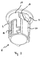
- Fig. 1 shows an exploded view of an operating element 1 according to the invention with an installation unit 2, which has a front plate 3 and a holding element 4.
- the operating element 1 can be designed as a pushbutton 5, in particular as a double pushbutton.
- the operating element 1 preferably has a two-part housing which comprises a rosette 6 and a front ring 7 mounted thereon.
- the rosette 6 has a cylindrical base body and is designed as a housing base.
- the front ring 7 acting as the upper housing part of the operating element 1 is preferably designed as a super ellipse and thus represents a mixture of ellipse and rectangle.
- the front ring 7 has a support surface 8 arranged on the underside, each of which is arranged on the right and left above the rosette centered under the front ring 7 6 protrudes.
- a push-button 5 is arranged in front ring 7 .
- At the rosette 6 at least one locking element 9 is arranged.
- the latching element 9 is preferably designed wing-shaped and has two mutually parallel flanks 10, which each open into introduction bevels 11. The insertion bevels 11 merge into the edge region 12 of the latching element 9.
- the front plate 3 is preferably formed in one piece and has two preferably at 90 ° to each other arranged surfaces 13, 14. In the surface 13 of the front panel 3, a cylindrical aperture 15 is arranged.
- the control element 1 can be introduced via the rosette 6 from above through the opening 15 in the front panel 3.
- the final fixation of the control element 1 is then carried out via a lower side to the front panel 3 arranged holding element 4, in which the rosette 6 of the control element 1 is inserted latching.
- the holding element 4 has a clamping screw 16, which allows a bracing of the holding element 4 against the front panel 3.
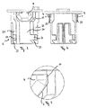
- Fig. 2 shows a perspective view of the cylindrical base body of the operating element 1.
- the formed as a rosette 6 main body preferably has wing-shaped locking elements 9 in the upper third of the rosette 6 in close proximity to the front ring 7.
- the outer geometry of the rosette 6 is structured, that is, there are both smooth surfaces 17 and recesses 18 on the outer edge of the rosette 6.
- the locking element 9 is arranged in a likewise wing-shaped recess 19 of the rosette 6, which opens into a guide channel 20 ,
- Fig. 3 shows a sectional view of the cylindrical base body of the operating element 1 with a front view of the locking element 9 according to the invention.
- the locking element 9 is arranged in the similarly shaped recess 19, which opens into the guide channel 20.
- the guide channel 20 is formed by two right and left of the guide channel 20 formed edge structures 21, 22. These edge structures 21, 22 have guide slopes 23 and recesses 24, which allow a targeted insertion and locking of the rosette 6 in the holding element 4.
- Fig. 4 shows a sectional view of the cylindrical base body of the operating element 1 with a side view of the locking elements 9.
- the locking elements 9 have in addition to the insertion bevels 11 and insertion radii 25, which facilitate the targeted insertion and locking of the rosette 6.
- Fig. 5 shows a sectional view of an enlarged detail Fig. 3 Shown are also the flanks 10 of the latching wing element and the insertion bevels 11th
- Fig. 6 shows a perspective view of lying on the front ring 7 control element 1 with molded plastic wing, the in Fig. 7 also shown again in an enlarged section.
- Such an embodiment with directly molded plastic wing is then provided when the rosette 6 is made of plastic.
- Fig. 8 shows a perspective view of lying on the front ring 7 control element 1 with pressed plastic wing, the in Fig. 9 also shown again in an enlarged section.
- a dome-shaped projection 26 is preferably arranged on the rosette 6. This projection 26 opens when pressing the plastic wing in a hole member 27, which is preferably centered in the plastic wing is arranged.
- Fig. 10 shows a perspective view of an operating element 1 with an accessory 28th
- Fig. 11 shows a bottom view of the control element 1 with accessory 28.
- the flanks 10 of the locking elements 9 are applied to tooth flanks 29 of the accessory 28 at.
- These tooth flanks 29 are preferably arranged at defined intervals, for example in 90 ° steps, so that the operating element 1 can be positioned without defined components at defined distances from the accessory 28. If the position is chosen incorrectly, the accessory 28 can simply be further rotated to finally re-engage in the following position.
- Fig. 12 The functionless closure stopper 30 or dummy plugs offer in their inner space for receiving a molded spring element 31.
- the insertion radii 31 (FIG. Fig. 13 ).
- Fig. 13 shows a bottom view of the functionless sealing plug 30 after Fig. 12 .
- control element according to the invention with improved installation unit allows easy one-handed installation, which is implemented via locking elements.
Description
- Die Erfindung betrifft ein Bedienelement mit Installations-einheit, die eine Frontplatte sowie ein Halteelement aufweist.
- Eine derartige Installationseinheit kommt bei Maschinen oder elektrischen Anlagen zum Einsatz, die über Befehlsgeräte, wie zum Beispiel Drucktaster, Wahlschalter usw., die auf die Steuerung einwirken, bedient werden. Diese Befehlsgeräte werden in Schalttafeln, Bedientableaus, Schaltschranktüren oder Gehäusedeckeln montiert. Befehlsgeräte sind in der Regel modular aufgebaut; das bedeutet, sie bestehen aus einem Betätiger, einem Befestigungsteil wie zum Beispiel einer Ringmutter oder einem Montagehalter und einem oder mehreren Schaltelementen, die als Öffner- oder Schließerschaltglieder ausgeführt sind. Zur Montage wird der Betätiger in der Regel von vorne durch ein Loch in der Schalttafel geführt und von hinten mittels eines Befestigungsteils montiert. Die Schaltelemente werden mit Schrauben, Schnapphaken oder Riegel mechanisch in dem Betätiger oder dem Befestigungsteil verbunden. Die elektrische Verbindung der Schaltelemente mit der Steuerung erfolgt über die Anschlussklemmen.
- Bei Sicherheitsanwendungen wie zum Beispiel Not-Aus-Befehlsgeräten ist es Vorschrift, dass das Signal durch das Öffnen von zwangsöffnenden Kontakten erzeugt wird. Das heißt, dass bei einem unbetätigten Not-Aus-Befehlsgerät die Kontakte und damit der zugehörige Stromkreis geschlossen sind. Im Störungs- oder Notfall wird durch Schlagen auf den Not-Aus-Betätiger, der sich vor der Schaltertafel befindet, der Öffnerkontakt unterbrochen und die Anlage oder Maschine in einen sicheren Zustand versetzt. Dies funktioniert jedoch nur, wenn die räumliche Zuordnung zwischen Betätiger und Schaltelement sichergestellt ist. Durch mangelhafte Montage oder durch Gewalteinwirkung kann es vorkommen, dass die Schaltelemente mechanisch vom Betätiger getrennt werden. In diesem Fall ist das Not-Aus-Befehlsgerät nicht mehr funktionsfähig, das heißt, bei einer Betätigung im Notfall werden die Kontakte nicht geöffnet, und damit erfolgt auch keine Beseitigung des-Gefahrenzustands. Dies kann zu fatalen Schäden für Mensch und Maschine führen. Daher kommt der sicheren Verbindung zwischen Betätiger und Schaltelement eine wesentliche Bedeutung zu.
- Aus der
DE 37 09 970 C2 geht dazu ein Gehäuse hervor, das in die Öffnung einer Schalttafel eingeschoben wird. Zur Befestigung des Gehäuses in der Aufnahmewand sind in zwei gegenüberliegenden Seitenwänden im Kantenbereich Nuten vorgesehen, die mit ihren Enden an die benachbarten Gehäuseseiten münden. In diesen Nuten ist ein als Federbandstreifen ausgebildetes Befestigungselement hochkant eingesetzt. Die Tiefe der Nuten ist im Wesentlichen gleich der Breite des Federbandstreifens und die Breite der Nut ist nur unwesentlich größer als die Stärke des Federbandmaterials. Die Nuten liegen im Wesentlichen im Bereich der Verstärkungsstege, so dass ausreichend Material für ihre Aufnahme vorhanden ist. Der Federbandstreifen liegt mit einem mittleren Längsabschnitt hochkant in der Nut, während seine beiden äußeren Längsabschnitte aus der benachbarten Seitenwand heraustreten, wobei diese Längsabschnitte, die die an der Aufnahmewand anliegenden Federelemente bilden, derart bogenförmig verlaufen, dass ihre Enden sich wieder mehr oder weniger der Gehäuseseitenwand nähern. - Die
DE 100 34 253 C1 beschreibt ein in einer Bedientafel befestigbares Befehlsgerät, bei dem ein Zwischenelement frontseitig mit einem äußeren Auflageelement an einer Bedientafel anliegt und in einem inneren Auflageelement in einer Ausnehmung in der Bedientafel hinein beziehungsweise durch die Ausnehmung hindurchragt. Ein Signalgeber liegt frontseitig mit einem Auflagebereich am inneren Auflageelement an und reicht in einem Durchtrittsbereich durch das Zwischenelement und die Bedientafel hindurch. Ein Geberhalter ist rückseitig an die Bedientafel ansetzbar und mit dem Durchtrittsbereich verspannbar. - Aus der
DE 43 42 512 A1 geht eine elektrische Einbaudose hervor, die zur elektrischen Installation von elektrischen Baugruppen wie Schalter, Stecker oder Verteiler dient. Es wird eine universell einsetzbare Einbaudose vorgeschlagen, die ohne zu verschraubende und/oder zu verspannende Elemente in eine Montageöffnung fest eingesetzt werden kann. Die Einbaudose weist an diametral angeordneten Abflachungen des Außenmantels Stützelemente auf, deren freie Enden mit einem bogenförmig gekrümmten, eine Verzahnung tragenden Drucksteg verbunden sind, wobei die Stirnfläche des Drucksteges bis nahe an den Stützrand herangeführt ist. In einem schräg ausgebildeten Mantelabschnitt sind in diametraler Anordnung Rohrstützen vorgesehen, die so ausgebildet sind, dass mehrere in benachbarter Anordnung anzubringende Einbaudosen über ein elastisches Zwischenstück miteinander verbunden werden können. Die Einbaudose wird durch einfaches Eindrücken in die Montageöffnung lagegenau befestigt, wobei zwischen den Druckstegen und der benachbarten Wand der Montageöffnung eine feste form-schlüssige Klemmverbindung hergestellt wird. Das DokumentEP 0037896 offenbart ein Bedienelement gemäss dem Oberbegriff des Anspruchs 1. - Die Aufgabe der vorliegenden Erfindung besteht darin, ein Bedienelement mit einer verbesserter Installationseinheit zu schaffen, das eine einfache Einhand-Montage ermöglicht.
- Diese Aufgabe wird durch ein Bedienelement mit den Merkmalen des Patentanspruchs 1 gelöst. Vorteilhafte Aus- und Weiterbildungen, welche einzeln oder in Kombination miteinander eingesetzt werden können, sind der Gegenstand der abhängigen Ansprüche.
- Erfindungsgemäß wird diese Aufgabe durch ein Bedienelement mit einer Installationseinheit gelöst, die eine Frontplatte sowie ein Halteelement aufweist, wobei das Bedienelement vorzugsweise als elektrischer Schalter ausgebildet ist und mindestens ein Rastelement aufweist, und wobei das Bedienelement durch eine Öffnung bzw. einen Durchbruch in der Frontplatte in das Halteelement durch das mindestens eine Rastelement verrastend einführbar ist.
- Vorzugsweise weist das Bedienelement zwei Rastelemente auf, die aus Kunststoff gefertigt sind. Beim axialen Einpressen des Bedienelementes in den vorzugsweise zylindrischen Frontplattendurchbruch werden die vorzugsweise elastischen Randelemente in das Halteelement eingeführt. Die als Kunststoffflügel ausgebildeten Rastelemente weisen vorzugsweise Einführungsschrägen und Einführungsradien auf. Beim Einführen des Bedienelements in den Frontplattendurchbruch legen sich die Kunststoffflügel an die Wandungen des Frontplattendurchbruchs an. Aus dieser Zwangslage resultieren Spannungen in den Kunststoffflügeln, die sich gegen den Frontplattendurchbruch richten und damit das Bedienelement in der Frontplatte fixieren.
- Das erfindungsgemäße Bedienelement mit Installationseinheit erfordert eine Montagekraft von maximal 8 bis 10 Newton. Erfindungswesentlich ist es, nach dem Einpressen des Bedienelementes in den Frontplattendurchbruch eine ausreichend große Spannkraft aufzubringen, um das komplette Halteelement in jeder Einbaulage sicher montieren zu können. Die Lösung zeichnet sich dadurch aus, dass je nach Toleranzlage der Frontplattendurchbrüche, der Kunststoffflügel oder der Umgebungstemperatur eine Spannkraft von maximal 45 Newton und mindestens 12 Newton aufgebracht wird. Dadurch wird selbst bei ungünstigen Einbauverhältnissen eine hohe Funktionalität gewährleistet.
- Die Einführungsschrägen beziehungsweise Einführungsradien der erfindungsgemäßen Rastelemente haben eine zentrierende Funktion, die durch die flexiblen Flanken der Kunststoffflügel auch größere Schwankungen in den Formtoleranzen des Frontplattendurchbruchs ausgleichen. Die Kunststoffflügel dienen weiterhin zur Lageorientierung von Zubehörteilen. Dazu besitzen die Zubehörteile zahnförmige Aussparungen und sind zum Bedienelement positionierbar. Dieser weitere Nutzen erfordert keine ergänzenden Bauteile.
- Als Werkstoff für die erfindungsgemäßen Kunststoffflügel wird vorzugsweise Ultramid A3WG7/PA66 GF35 eingesetzt. Dies ist eine glasfaserverstärkte und wärmealterungsbeständige Spritzgussmasse für technische Artikel wie Zahnräder, Magnetventilgehäuse, Kabelschlepper, Kfz-Kraftstoffverteiler und Bauteile für Kfz-Gangschaltungen. Die Alterungsbeständigkeit führt dazu, dass selbst nach mehrmaliger Montage die Kunststoffflügel noch eine ausreichende Spannkraft aufbringen, um die Montagekraft des Halteelements sicher zu überwinden. Die hohe Funktionalität und Prozesssicherheit der erfindungsgemäßen Kunststoffflügel ermöglicht automatisierte Montagevorgänge.
- Wird das Gehäuse des Bedienelementes aus Kunststoff ausgebildet, so werden die Kunststoffflügel direkt angespritzt. In der Druckgussausführung werden die Kunststoffflügel auf die Metallrosette aufgepresst. Die Flanken der Kunststoffflügel legen sich beim Einpressen in die Zubehörteile an die Zahnflanken an. Dadurch ist es möglich, ohne weitere Bauteile in 90° Schritten Zubehörteile zu Befehlsgeräten zu positionieren. Wird die Position falsch gewählt, kann das Zubehörteil einfach weitergedreht werden, um schließlich in der folgenden Position erneut einzurasten.
- Gemäß der vorliegenden Erfindung ist es auch möglich, eine halterlose Dauermontage von Blindstopfen zu realisieren. Die in ihrem inneren funktionslosen Verschlussstopfen bieten Platz zur Aufnahme eines angespritzten Federelementes. An beiden Enden der Federelemente werden Spannbacken angeformt.
- Weitere Vorteile und Ausführungen der Erfindung werden nachfolgend anhand von Ausführungsbeispielen sowie anhand der Zeichnung erläutert.
- Dabei zeigen schematisch:
- Fig. 1
- eine Explosionsdarstellung eines erfindungsgemäßen Bedienelements mit Installationseinheit;
- Fig. 2
- eine perspektivische Darstellung des Bedienelements;
- Fig. 3
- eine Schnittdarstellung des Bedienelements mit einer Frontansicht der erfindungsgemäßen Rastelemente;
- Fig. 4
- eine Schnittdarstellung des Bedienelements mit einer Seitenansicht der Rastelemente nach
Fig. 3 ; - Fig. 5
- eine Schnittdarstellung eines vergrößerten Ausschnitts aus
Fig. 3 mit dem erfindungsgemäßen Rastelement; - Fig. 6
- eine perspektivische Darstellung des auf dem Kopf liegenden Bedienelements mit angespritzten Kunststoffflügeln;
- Fig. 7
- eine perspektivische Darstellung eines vergrößerten Ausschnitts aus
Fig.6 ; - Fig. 8
- eine perspektivische Darstellung des auf dem Kopf liegenden Bedienelements mit aufgesteckten Kunststoffflügeln;
- Fig. 9
- eine perspektivische Darstellung eines vergrößerten Ausschnitts aus
Fig.8 ; - Fig. 10
- eine perspektivische Darstellung des Bedienelements mit Zubehörteil;
- Fig. 11
- eine Unteransicht des Bedienelements mit Zubehörteil nach
Fig.10 ; - Fig. 12
- eine perspektivische Darstellung eines als funktionslosen Verschlussstopfens ausgeführten Bedienelements;
- Fig. 13
- eine Unteransicht des funktionslosen Verschlussstopfens nach
Fig.12 . -
Fig. 1 zeigt eine Explosionsdarstellung eines erfindungsgemäßen Bedienelements 1 mit einer Installationseinheit 2, die eine Frontplatte 3 sowie ein Halteelement 4 aufweist. Das Bedienelement 1 kann als Drucktaster 5, insbesondere als Doppeldrucktaster ausgeführt sein. Das Bedienelement 1 weist vorzugsweise ein zweiteiliges Gehäuse auf, das eine Rosette 6 und einen darauf aufgesetzten Frontring 7 umfasst. Die Rosette 6 weist einen zylindrischen Grundkörper auf und ist als Gehäuseunterteil ausgeführt. Der als Gehäuseoberteil des Bedienelements 1 fungierende Frontring 7 ist vorzugsweise als Superellipse ausgebildet und stellt somit eine Mischung aus Ellipse und Rechteck dar. Der Frontring 7 weist eine unterseitig angeordnete Auflagefläche 8 auf, die jeweils rechts und links über die zentriert unter dem Frontring 7 angeordnete Rosette 6 hinausragt. Im Frontring 7 ist mindestens ein Drucktaster 5 angeordnet. An der Rosette 6 ist mindestens ein Rastelement 9 angeordnet. Das Rastelement 9 ist vorzugsweise flügelförmig ausgebildet und weist zwei parallel zueinander verlaufende Flanken 10 auf, die jeweils in Einführungsschrägen 11 münden. Die Einführungsschrägen 11 gehen in den Kantenbereich 12 des Rastelements 9 über. - Die Frontplatte 3 ist vorzugsweise einteilig ausgebildet und weist zwei vorzugsweise im 90° Winkel zueinander angeordnete Flächen 13, 14 auf. In der Fläche 13 der Frontplatte 3 ist ein zylindrischer Durchbruch 15 angeordnet. Das Bedienelement 1 kann so über die Rosette 6 von oben durch den Durchbruch 15 in der Frontplatte 3 eingeführt werden. Die Endfixierung des Bedienelements 1 erfolgt dann über ein unterseitig zur Frontplatte 3 angeordnetes Halteelement 4, in welchem die Rosette 6 des Bedienelements 1 verrastend eingeführt wird. Das Halteelement 4 weist eine Spannschraube 16 auf, die ein Verspannen des Halteelements 4 gegen die Frontplatte 3 ermöglicht.
-
Fig. 2 zeigt eine perspektivische Darstellung des zylindrischen Grundkörpers des Bedienelements 1. Der als Rosette 6 ausgebildete Grundkörper weist vorzugsweise flügelförmige Rastelemente 9 im oberen Drittel der Rosette 6 in unmittelbarer Nähe zum Frontring 7 auf. Die Außengeometrie der Rosette 6 ist strukturiert ausgebildet, das heißt, es gibt sowohl glatte Flächen 17 als auch Ausnehmungen 18 am Außenrand der Rosette 6. Das Rastelement 9 ist in einer ebenfalls flügelförmig ausgebildeten Aussparung 19 der Rosette 6 angeordnet, die in einen Führungskanal 20 mündet. -
Fig. 3 zeigt eine Schnittdarstellung des zylindrischen Grundkörpers des Bedienelements 1 mit einer Frontansicht des erfindungsgemäßen Rastelements 9. Das Rastelement 9 ist in der ebenso ausgeformten Aussparung 19 angeordnet, die in den Führungskanal 20 mündet. Der Führungskanal 20 wird durch zwei rechts und links vom Führungskanal 20 ausgebildeten Randstrukturen 21, 22 ausgebildet. Diese Randstrukturen 21, 22 weisen Führungsschrägen 23 sowie Aussparungen 24 auf, die ein zielgerichtetes Einführen und Verrasten der Rosette 6 im Halteelement 4 ermöglichen. -
Fig. 4 zeigt eine Schnittdarstellung des zylindrischen Grundkörpers des Bedienelements 1 mit einer Seitenansicht der Rastelemente 9. Die Rastelemente 9 weisen neben den Einführungsschrägen 11 auch Einführungsradien 25 auf, die das zielgerichtete Einführen und Verrasten der Rosette 6 erleichtern. -
Fig. 5 zeigt eine Schnittdarstellung eines vergrößerten Ausschnitts ausFig. 3 mit dem erfindungsgemäßen Rastelement 9. Dargestellt sind außerdem die Flanken 10 des verrastenden Flügelelementes sowie die Einführungsschrägen 11. -
Fig. 6 zeigt eine perspektivische Darstellung des auf dem Frontring 7 liegenden Bedienelements 1 mit angespritztem Kunststoffflügel, der inFig. 7 in einem vergrößerten Ausschnitt ebenfalls noch mal dargestellt ist. Eine derartige Ausführungsform mit direkt angespritztem Kunststoffflügel ist dann vorgesehen, wenn die Rosette 6 aus Kunststoff gefertigt ist. -
Fig. 8 zeigt eine perspektivische Darstellung des auf dem Frontring 7 liegenden Bedienelements 1 mit angepresstem Kunststoffflügel, der inFig. 9 in einem vergrößerten Ausschnitt ebenfalls noch mal dargestellt ist. Eine derartige Ausführungsform mit aufgepresstem Kunststoffflügel ist dann vorgesehen, wenn die Rosette 6 aus Metall gefertigt ist. Um das Rastelement 9 auf die Rosette 6 aufpressen zu können, ist an der Rosette 6 vorzugsweise ein domförmiger Vorsprung 26 angeordnet. Dieser Vorsprung 26 mündet beim Aufpressen des Kunststoffflügels in ein Lochelement 27, das vorzugsweise zentriert im Kunststoffflügel angeordnet ist. -
Fig. 10 zeigt eine perspektivische Darstellung eines Bedienelements 1 mit einem Zubehörteil 28.Fig. 11 zeigt eine Unteransicht des Bedienelements 1 mit Zubehörteil 28. Beim Einpressen in das Zubehörteil 28 legen sich die Flanken 10 der Rastelemente 9 an Zahnflanken 29 des Zubehörteils 28 an. Diese Zahnflanken 29 sind vorzugsweise in definierten Abständen beispielsweise in 90° Schritten angeordnet, so dass das Bedienelement 1 ohne weitere Bauteile in definierten Abständen zum Zubehörteil 28 positioniert werden kann. Wird die Position falsch gewählt, kann das Zubehörteil 28 einfach weitergedreht werden, um schließlich in der folgenden Position erneut einzurasten. -
Fig. 12 zeigt eine perspektivische Darstellung eines als funktionslosen Verschlussstopfens 30 ausgebildeten Bedienelements 1. Die funktionslosen Verschlussstopfen 30 oder auch Blindstopfen bieten in ihrem inneren Platz zur Aufnahme eines angespritzten Federelements 31. Außenseitig sind am zylindrischen Grundkörper des Bedienelements 1 Spannbacken 32 angeordnet, die Einführungsradien 31 aufweisen (Fig. 13 ). -
Fig. 13 zeigt eine Unteransicht des funktionslosen Verschlussstopfens 30 nachFig. 12 . - Das erfindungsgemäße Bedienelement mit verbesserter Installationseinheit ermöglicht eine einfache Einhand-Montage, die über Rastelemente umgesetzt wird.
Claims (8)
- Bedienelement mit einer Installationseinheit, die eine Frontplatte (3) sowie ein Halteelement (4) aufweist, wobei das Bedienelement (1) eine Rosette (6) und einen darauf aufgesetzten Frontring (7) und mindestens ein Rastelement (9) aufweist und durch einen Durchbruch (15) in der Frontplatte (3) in das Halteelement (4) durch das mindestens eine Rastelement (9) verrastend einführbar ist, dadurch gekennzeichnet, dass das Rastelement (9) als Flügel mit Einführungsschrägen (11) ausgebildet ist, wobei das flügelförmige Rastelement (9) im oberen Drittel der Rosette (6) in unmittelbarer Nähe zum Frontring (7) angeordnet ist, und wobei das Rastelement (9) in einer flügelförmig ausgebildeten Aussparung (19) der Rosette (6) angeordnet ist, die in einen Führungskanal (20) mündet.
- Bedienelement nach Anspruch 1, dadurch gekennzeichnet, dass die Frontplatte (3) durch das mindestens eine Rastelement (9) am Bedienelement (1) verliersicher fixiert ist.
- Bedienelement nach Anspruch 1 oder 2, dadurch gekennzeichnet, dass das Rastelement (9) aus Kunststoff gefertigt ist.
- Bedienelement nach einem der vorhergehenden Ansprüche, dadurch gekennzeichnet, dass das mindestens eine Rastelement (9) elastisch ausgebildet ist.
- Bedienelement nach einem der vorhergehenden Ansprüche, dadurch gekennzeichnet, dass das Rastelement (9) Einführungsradien (25) aufweist.
- Bedienelement nach einem der vorhergehenden Ansprüche, dadurch gekennzeichnet, dass Bedienelement (1) einen Frontring (3) und eine Rosette (6) aufweist, an die das mindestens eine Rastelement (9) angespritzt ist.
- Bedienelement nach einem der vorhergehenden Ansprüche, dadurch gekennzeichnet, dass bei Bedienelementen (1) mit Metallrosette das mindestens eine Rastelement (9) aufgepresst ist.
- Bedienelement nach Anspruch 1, dadurch gekennzeichnet, dass das Bedienelement als funktionsloser Verschlusstopfen (30) mit Rosette (6) ausgebildet ist.
Applications Claiming Priority (1)
| Application Number | Priority Date | Filing Date | Title |
|---|---|---|---|
| PCT/EP2008/005780 WO2010006625A1 (de) | 2008-07-15 | 2008-07-15 | Bedienelement mit installationseinheit |
Publications (2)
| Publication Number | Publication Date |
|---|---|
| EP2301123A1 EP2301123A1 (de) | 2011-03-30 |
| EP2301123B1 true EP2301123B1 (de) | 2013-10-02 |
Family
ID=40473603
Family Applications (1)
| Application Number | Title | Priority Date | Filing Date |
|---|---|---|---|
| EP08784788.5A Not-in-force EP2301123B1 (de) | 2008-07-15 | 2008-07-15 | Bedienelement mit installationseinheit |
Country Status (4)
| Country | Link |
|---|---|
| EP (1) | EP2301123B1 (de) |
| CN (1) | CN102084562B (de) |
| BR (1) | BRPI0822941B1 (de) |
| WO (1) | WO2010006625A1 (de) |
Families Citing this family (1)
| Publication number | Priority date | Publication date | Assignee | Title |
|---|---|---|---|---|
| DE102010041041A1 (de) * | 2010-09-20 | 2012-03-22 | Siemens Aktiengesellschaft | Installationseinheit für die Fixierung von Befehls- und Meldegeräten an Frontplatten |
Family Cites Families (5)
| Publication number | Priority date | Publication date | Assignee | Title |
|---|---|---|---|---|
| DE2609473C3 (de) * | 1976-03-08 | 1978-11-30 | Pistor & Kroenert, Gmbh U. Co, 5880 Luedenscheid | Elektrisches Installationsgerät (Signalleuchte, Schaltgerät u.dgl.) zum Einbau in eine öffnung einer Trägerplatte |
| DE3014368C2 (de) * | 1980-04-15 | 1983-10-27 | R. Stahl Schaltgeräte GmbH, 7118 Künzelsau | Schalttafeleinbaugerät zur Einlochmontage in Schalttafeln |
| CH666952A5 (fr) * | 1986-04-24 | 1988-08-31 | Universo Sa | Porte-lampe miniature. |
| US5542859A (en) * | 1994-11-16 | 1996-08-06 | Woods Industries, Inc. | Quick mount electrical wall socket |
| DE10330853B4 (de) * | 2003-07-09 | 2006-08-03 | WEG Indústrias S.A., Jaraguá do Sul | Schnappmechanismus für das Befestigen eines Flansches an eine Befehls- oder Meldeeinheit |
-
2008
- 2008-07-15 EP EP08784788.5A patent/EP2301123B1/de not_active Not-in-force
- 2008-07-15 WO PCT/EP2008/005780 patent/WO2010006625A1/de active Application Filing
- 2008-07-15 BR BRPI0822941A patent/BRPI0822941B1/pt not_active IP Right Cessation
- 2008-07-15 CN CN200880130206.9A patent/CN102084562B/zh not_active Expired - Fee Related
Also Published As
| Publication number | Publication date |
|---|---|
| BRPI0822941A2 (pt) | 2018-03-13 |
| WO2010006625A1 (de) | 2010-01-21 |
| CN102084562A (zh) | 2011-06-01 |
| CN102084562B (zh) | 2014-01-15 |
| EP2301123A1 (de) | 2011-03-30 |
| BRPI0822941B1 (pt) | 2019-01-22 |
Similar Documents
| Publication | Publication Date | Title |
|---|---|---|
| EP1269580A1 (de) | Elektronische baugruppe | |
| EP1714839A1 (de) | Vorrichtung zur Verriegelung und schnellen Entriegelung von beweglichen Bauteilen | |
| WO2009062698A1 (de) | Türantrieb mit einer antriebseinheit | |
| WO2009115080A2 (de) | Vorrichtung zur realisierung eines trockenen elektrischen anschlusses eines kraftfahrzeugschlosses | |
| EP2301123B1 (de) | Bedienelement mit installationseinheit | |
| EP1398223B1 (de) | Vorrichtung zur Befestigung eines Stossfängerüberzugs an einem Fahrzeug, insbesondere an einem Kraftfahrzeug | |
| EP2704272B1 (de) | Befehls- und meldegerät zur montage in eine montagebohrung einer montageplatte | |
| EP2704273B1 (de) | Befehls- und Meldegerät zur montage in eine Montagebohrung einer Montageplatte | |
| DE202012008253U1 (de) | Befehls- und Meldegerät | |
| DE102010041041A1 (de) | Installationseinheit für die Fixierung von Befehls- und Meldegeräten an Frontplatten | |
| DE202010000903U1 (de) | Vorrichtung zur Zugentlastung und Gehäusewand-Durchführung von Litzen und Encoder | |
| DE19925859B4 (de) | Montagehilfe für eine Kraftfahrzeugtürkonstruktion | |
| EP2960914B1 (de) | Verfahren zur Herstellung eines Drucktaster-Kompaktbauteils | |
| EP1571279A2 (de) | Kraftfahrzeugtürschlosseinrichtung | |
| EP2697542B1 (de) | Befehls- und meldevorrichtung | |
| EP1355387B1 (de) | Elektrischer Steckverbinderanordnung an einem ortsfesten Karosserieteil eines Kraftfahrzeugs und Verfahren zur Bildung einer solchen elektrischen Steckverbindung | |
| DE102021121544A1 (de) | Elektromotorische Stellvorrichtung für kraftfahrzeugtechnische Anwendungen | |
| WO2023246970A1 (de) | Kraftfahrzeug-schloss-baugruppe sowie verfahren zu seiner herstellung | |
| DE202012008252U1 (de) | Befehls- und Meldegerät | |
| DE102020126918A1 (de) | Gehäuseanordnung für einen elektrischen Stecker mit einem Bedienungshebel sowie elektrischer Stecker und Steckeranordnung | |
| WO2002046558A1 (de) | In einer wandöffnung montierbarer betätiger für verschlüsse im fahrzeug | |
| DE102020104994A1 (de) | Kabeleinlassvorrichtung für einen Schaltschrank sowie Anordnung und Verfahren zum Betrieb derselben | |
| WO2023186213A1 (de) | Antriebseinheit für kraftfahrzeug-technische anwendungen | |
| WO2009003917A1 (de) | Lenksäulenmodul für ein kraftfahrzeug | |
| DE102011078639A1 (de) | Befehls- und Meldevorrichtung |
Legal Events
| Date | Code | Title | Description |
|---|---|---|---|
| PUAI | Public reference made under article 153(3) epc to a published international application that has entered the european phase |
Free format text: ORIGINAL CODE: 0009012 |
|
| 17P | Request for examination filed |
Effective date: 20101202 |
|
| AK | Designated contracting states |
Kind code of ref document: A1 Designated state(s): AT BE BG CH CY CZ DE DK EE ES FI FR GB GR HR HU IE IS IT LI LT LU LV MC MT NL NO PL PT RO SE SI SK TR |
|
| AX | Request for extension of the european patent |
Extension state: AL BA MK RS |
|
| RIN1 | Information on inventor provided before grant (corrected) |
Inventor name: BECK, RONNY Inventor name: HIRSCHBERGER, FRANK |
|
| DAX | Request for extension of the european patent (deleted) | ||
| RAP1 | Party data changed (applicant data changed or rights of an application transferred) |
Owner name: SIEMENS AKTIENGESELLSCHAFT |
|
| GRAP | Despatch of communication of intention to grant a patent |
Free format text: ORIGINAL CODE: EPIDOSNIGR1 |
|
| INTG | Intention to grant announced |
Effective date: 20130422 |
|
| GRAS | Grant fee paid |
Free format text: ORIGINAL CODE: EPIDOSNIGR3 |
|
| GRAA | (expected) grant |
Free format text: ORIGINAL CODE: 0009210 |
|
| AK | Designated contracting states |
Kind code of ref document: B1 Designated state(s): AT BE BG CH CY CZ DE DK EE ES FI FR GB GR HR HU IE IS IT LI LT LU LV MC MT NL NO PL PT RO SE SI SK TR |
|
| REG | Reference to a national code |
Ref country code: GB Ref legal event code: FG4D Free format text: NOT ENGLISH |
|
| REG | Reference to a national code |
Ref country code: CH Ref legal event code: EP Ref country code: AT Ref legal event code: REF Ref document number: 635025 Country of ref document: AT Kind code of ref document: T Effective date: 20131015 |
|
| REG | Reference to a national code |
Ref country code: IE Ref legal event code: FG4D Free format text: LANGUAGE OF EP DOCUMENT: GERMAN |
|
| REG | Reference to a national code |
Ref country code: DE Ref legal event code: R096 Ref document number: 502008010758 Country of ref document: DE Effective date: 20131128 |
|
| REG | Reference to a national code |
Ref country code: NL Ref legal event code: VDEP Effective date: 20131002 |
|
| PG25 | Lapsed in a contracting state [announced via postgrant information from national office to epo] |
Ref country code: SI Free format text: LAPSE BECAUSE OF FAILURE TO SUBMIT A TRANSLATION OF THE DESCRIPTION OR TO PAY THE FEE WITHIN THE PRESCRIBED TIME-LIMIT Effective date: 20131002 |
|
| REG | Reference to a national code |
Ref country code: LT Ref legal event code: MG4D |
|
| PG25 | Lapsed in a contracting state [announced via postgrant information from national office to epo] |
Ref country code: NO Free format text: LAPSE BECAUSE OF FAILURE TO SUBMIT A TRANSLATION OF THE DESCRIPTION OR TO PAY THE FEE WITHIN THE PRESCRIBED TIME-LIMIT Effective date: 20140102 Ref country code: FI Free format text: LAPSE BECAUSE OF FAILURE TO SUBMIT A TRANSLATION OF THE DESCRIPTION OR TO PAY THE FEE WITHIN THE PRESCRIBED TIME-LIMIT Effective date: 20131002 Ref country code: NL Free format text: LAPSE BECAUSE OF FAILURE TO SUBMIT A TRANSLATION OF THE DESCRIPTION OR TO PAY THE FEE WITHIN THE PRESCRIBED TIME-LIMIT Effective date: 20131002 Ref country code: IS Free format text: LAPSE BECAUSE OF FAILURE TO SUBMIT A TRANSLATION OF THE DESCRIPTION OR TO PAY THE FEE WITHIN THE PRESCRIBED TIME-LIMIT Effective date: 20140202 Ref country code: LT Free format text: LAPSE BECAUSE OF FAILURE TO SUBMIT A TRANSLATION OF THE DESCRIPTION OR TO PAY THE FEE WITHIN THE PRESCRIBED TIME-LIMIT Effective date: 20131002 Ref country code: SE Free format text: LAPSE BECAUSE OF FAILURE TO SUBMIT A TRANSLATION OF THE DESCRIPTION OR TO PAY THE FEE WITHIN THE PRESCRIBED TIME-LIMIT Effective date: 20131002 Ref country code: CZ Free format text: LAPSE BECAUSE OF FAILURE TO SUBMIT A TRANSLATION OF THE DESCRIPTION OR TO PAY THE FEE WITHIN THE PRESCRIBED TIME-LIMIT Effective date: 20131002 Ref country code: HR Free format text: LAPSE BECAUSE OF FAILURE TO SUBMIT A TRANSLATION OF THE DESCRIPTION OR TO PAY THE FEE WITHIN THE PRESCRIBED TIME-LIMIT Effective date: 20131002 |
|
| PG25 | Lapsed in a contracting state [announced via postgrant information from national office to epo] |
Ref country code: PL Free format text: LAPSE BECAUSE OF FAILURE TO SUBMIT A TRANSLATION OF THE DESCRIPTION OR TO PAY THE FEE WITHIN THE PRESCRIBED TIME-LIMIT Effective date: 20131002 Ref country code: CY Free format text: LAPSE BECAUSE OF FAILURE TO SUBMIT A TRANSLATION OF THE DESCRIPTION OR TO PAY THE FEE WITHIN THE PRESCRIBED TIME-LIMIT Effective date: 20131002 Ref country code: LV Free format text: LAPSE BECAUSE OF FAILURE TO SUBMIT A TRANSLATION OF THE DESCRIPTION OR TO PAY THE FEE WITHIN THE PRESCRIBED TIME-LIMIT Effective date: 20131002 Ref country code: ES Free format text: LAPSE BECAUSE OF FAILURE TO SUBMIT A TRANSLATION OF THE DESCRIPTION OR TO PAY THE FEE WITHIN THE PRESCRIBED TIME-LIMIT Effective date: 20131002 |
|
| PG25 | Lapsed in a contracting state [announced via postgrant information from national office to epo] |
Ref country code: PT Free format text: LAPSE BECAUSE OF FAILURE TO SUBMIT A TRANSLATION OF THE DESCRIPTION OR TO PAY THE FEE WITHIN THE PRESCRIBED TIME-LIMIT Effective date: 20140203 |
|
| REG | Reference to a national code |
Ref country code: DE Ref legal event code: R097 Ref document number: 502008010758 Country of ref document: DE |
|
| PG25 | Lapsed in a contracting state [announced via postgrant information from national office to epo] |
Ref country code: EE Free format text: LAPSE BECAUSE OF FAILURE TO SUBMIT A TRANSLATION OF THE DESCRIPTION OR TO PAY THE FEE WITHIN THE PRESCRIBED TIME-LIMIT Effective date: 20131002 |
|
| PLBE | No opposition filed within time limit |
Free format text: ORIGINAL CODE: 0009261 |
|
| STAA | Information on the status of an ep patent application or granted ep patent |
Free format text: STATUS: NO OPPOSITION FILED WITHIN TIME LIMIT |
|
| PG25 | Lapsed in a contracting state [announced via postgrant information from national office to epo] |
Ref country code: RO Free format text: LAPSE BECAUSE OF FAILURE TO SUBMIT A TRANSLATION OF THE DESCRIPTION OR TO PAY THE FEE WITHIN THE PRESCRIBED TIME-LIMIT Effective date: 20131002 Ref country code: SK Free format text: LAPSE BECAUSE OF FAILURE TO SUBMIT A TRANSLATION OF THE DESCRIPTION OR TO PAY THE FEE WITHIN THE PRESCRIBED TIME-LIMIT Effective date: 20131002 |
|
| 26N | No opposition filed |
Effective date: 20140703 |
|
| PG25 | Lapsed in a contracting state [announced via postgrant information from national office to epo] |
Ref country code: DK Free format text: LAPSE BECAUSE OF FAILURE TO SUBMIT A TRANSLATION OF THE DESCRIPTION OR TO PAY THE FEE WITHIN THE PRESCRIBED TIME-LIMIT Effective date: 20131002 |
|
| REG | Reference to a national code |
Ref country code: DE Ref legal event code: R097 Ref document number: 502008010758 Country of ref document: DE Effective date: 20140703 |
|
| PG25 | Lapsed in a contracting state [announced via postgrant information from national office to epo] |
Ref country code: LU Free format text: LAPSE BECAUSE OF FAILURE TO SUBMIT A TRANSLATION OF THE DESCRIPTION OR TO PAY THE FEE WITHIN THE PRESCRIBED TIME-LIMIT Effective date: 20140715 |
|
| REG | Reference to a national code |
Ref country code: CH Ref legal event code: PL |
|
| GBPC | Gb: european patent ceased through non-payment of renewal fee |
Effective date: 20140715 |
|
| REG | Reference to a national code |
Ref country code: IE Ref legal event code: MM4A |
|
| PG25 | Lapsed in a contracting state [announced via postgrant information from national office to epo] |
Ref country code: LI Free format text: LAPSE BECAUSE OF NON-PAYMENT OF DUE FEES Effective date: 20140731 Ref country code: CH Free format text: LAPSE BECAUSE OF NON-PAYMENT OF DUE FEES Effective date: 20140731 |
|
| PG25 | Lapsed in a contracting state [announced via postgrant information from national office to epo] |
Ref country code: GB Free format text: LAPSE BECAUSE OF NON-PAYMENT OF DUE FEES Effective date: 20140715 |
|
| PG25 | Lapsed in a contracting state [announced via postgrant information from national office to epo] |
Ref country code: IE Free format text: LAPSE BECAUSE OF NON-PAYMENT OF DUE FEES Effective date: 20140715 |
|
| REG | Reference to a national code |
Ref country code: AT Ref legal event code: MM01 Ref document number: 635025 Country of ref document: AT Kind code of ref document: T Effective date: 20140715 |
|
| PG25 | Lapsed in a contracting state [announced via postgrant information from national office to epo] |
Ref country code: AT Free format text: LAPSE BECAUSE OF NON-PAYMENT OF DUE FEES Effective date: 20140715 |
|
| PG25 | Lapsed in a contracting state [announced via postgrant information from national office to epo] |
Ref country code: NO Free format text: LAPSE BECAUSE OF FAILURE TO SUBMIT A TRANSLATION OF THE DESCRIPTION OR TO PAY THE FEE WITHIN THE PRESCRIBED TIME-LIMIT Effective date: 20140101 Ref country code: MC Free format text: LAPSE BECAUSE OF FAILURE TO SUBMIT A TRANSLATION OF THE DESCRIPTION OR TO PAY THE FEE WITHIN THE PRESCRIBED TIME-LIMIT Effective date: 20131002 |
|
| PG25 | Lapsed in a contracting state [announced via postgrant information from national office to epo] |
Ref country code: BG Free format text: LAPSE BECAUSE OF FAILURE TO SUBMIT A TRANSLATION OF THE DESCRIPTION OR TO PAY THE FEE WITHIN THE PRESCRIBED TIME-LIMIT Effective date: 20131002 |
|
| PG25 | Lapsed in a contracting state [announced via postgrant information from national office to epo] |
Ref country code: MT Free format text: LAPSE BECAUSE OF FAILURE TO SUBMIT A TRANSLATION OF THE DESCRIPTION OR TO PAY THE FEE WITHIN THE PRESCRIBED TIME-LIMIT Effective date: 20131002 Ref country code: GR Free format text: LAPSE BECAUSE OF FAILURE TO SUBMIT A TRANSLATION OF THE DESCRIPTION OR TO PAY THE FEE WITHIN THE PRESCRIBED TIME-LIMIT Effective date: 20140103 |
|
| REG | Reference to a national code |
Ref country code: FR Ref legal event code: PLFP Year of fee payment: 9 |
|
| PG25 | Lapsed in a contracting state [announced via postgrant information from national office to epo] |
Ref country code: BE Free format text: LAPSE BECAUSE OF FAILURE TO SUBMIT A TRANSLATION OF THE DESCRIPTION OR TO PAY THE FEE WITHIN THE PRESCRIBED TIME-LIMIT Effective date: 20140731 Ref country code: HU Free format text: LAPSE BECAUSE OF FAILURE TO SUBMIT A TRANSLATION OF THE DESCRIPTION OR TO PAY THE FEE WITHIN THE PRESCRIBED TIME-LIMIT; INVALID AB INITIO Effective date: 20080715 Ref country code: TR Free format text: LAPSE BECAUSE OF FAILURE TO SUBMIT A TRANSLATION OF THE DESCRIPTION OR TO PAY THE FEE WITHIN THE PRESCRIBED TIME-LIMIT Effective date: 20131002 |
|
| REG | Reference to a national code |
Ref country code: FR Ref legal event code: PLFP Year of fee payment: 10 |
|
| REG | Reference to a national code |
Ref country code: FR Ref legal event code: PLFP Year of fee payment: 11 |
|
| PGFP | Annual fee paid to national office [announced via postgrant information from national office to epo] |
Ref country code: DE Payment date: 20190919 Year of fee payment: 12 Ref country code: FR Payment date: 20190716 Year of fee payment: 12 Ref country code: IT Payment date: 20190729 Year of fee payment: 12 |
|
| REG | Reference to a national code |
Ref country code: DE Ref legal event code: R119 Ref document number: 502008010758 Country of ref document: DE |
|
| PG25 | Lapsed in a contracting state [announced via postgrant information from national office to epo] |
Ref country code: FR Free format text: LAPSE BECAUSE OF NON-PAYMENT OF DUE FEES Effective date: 20200731 |
|
| PG25 | Lapsed in a contracting state [announced via postgrant information from national office to epo] |
Ref country code: DE Free format text: LAPSE BECAUSE OF NON-PAYMENT OF DUE FEES Effective date: 20210202 |
|
| PG25 | Lapsed in a contracting state [announced via postgrant information from national office to epo] |
Ref country code: IT Free format text: LAPSE BECAUSE OF NON-PAYMENT OF DUE FEES Effective date: 20200715 |