EP2300713B1 - Verfahren und vorrichtung zum fördern von verdichtetem gas - Google Patents
Verfahren und vorrichtung zum fördern von verdichtetem gas Download PDFInfo
- Publication number
- EP2300713B1 EP2300713B1 EP09753311A EP09753311A EP2300713B1 EP 2300713 B1 EP2300713 B1 EP 2300713B1 EP 09753311 A EP09753311 A EP 09753311A EP 09753311 A EP09753311 A EP 09753311A EP 2300713 B1 EP2300713 B1 EP 2300713B1
- Authority
- EP
- European Patent Office
- Prior art keywords
- pressure
- gas
- low
- compressor
- pipeline section
- Prior art date
- Legal status (The legal status is an assumption and is not a legal conclusion. Google has not performed a legal analysis and makes no representation as to the accuracy of the status listed.)
- Active
Links
Images



Classifications
-
- F—MECHANICAL ENGINEERING; LIGHTING; HEATING; WEAPONS; BLASTING
- F04—POSITIVE - DISPLACEMENT MACHINES FOR LIQUIDS; PUMPS FOR LIQUIDS OR ELASTIC FLUIDS
- F04B—POSITIVE-DISPLACEMENT MACHINES FOR LIQUIDS; PUMPS
- F04B25/00—Multi-stage pumps
-
- F—MECHANICAL ENGINEERING; LIGHTING; HEATING; WEAPONS; BLASTING
- F04—POSITIVE - DISPLACEMENT MACHINES FOR LIQUIDS; PUMPS FOR LIQUIDS OR ELASTIC FLUIDS
- F04B—POSITIVE-DISPLACEMENT MACHINES FOR LIQUIDS; PUMPS
- F04B23/00—Pumping installations or systems
- F04B23/04—Combinations of two or more pumps
-
- F—MECHANICAL ENGINEERING; LIGHTING; HEATING; WEAPONS; BLASTING
- F04—POSITIVE - DISPLACEMENT MACHINES FOR LIQUIDS; PUMPS FOR LIQUIDS OR ELASTIC FLUIDS
- F04B—POSITIVE-DISPLACEMENT MACHINES FOR LIQUIDS; PUMPS
- F04B41/00—Pumping installations or systems specially adapted for elastic fluids
- F04B41/06—Combinations of two or more pumps
-
- F—MECHANICAL ENGINEERING; LIGHTING; HEATING; WEAPONS; BLASTING
- F04—POSITIVE - DISPLACEMENT MACHINES FOR LIQUIDS; PUMPS FOR LIQUIDS OR ELASTIC FLUIDS
- F04B—POSITIVE-DISPLACEMENT MACHINES FOR LIQUIDS; PUMPS
- F04B49/00—Control, e.g. of pump delivery, or pump pressure of, or safety measures for, machines, pumps, or pumping installations, not otherwise provided for, or of interest apart from, groups F04B1/00 - F04B47/00
- F04B49/007—Installations or systems with two or more pumps or pump cylinders, wherein the flow-path through the stages can be changed, e.g. from series to parallel
-
- F—MECHANICAL ENGINEERING; LIGHTING; HEATING; WEAPONS; BLASTING
- F04—POSITIVE - DISPLACEMENT MACHINES FOR LIQUIDS; PUMPS FOR LIQUIDS OR ELASTIC FLUIDS
- F04B—POSITIVE-DISPLACEMENT MACHINES FOR LIQUIDS; PUMPS
- F04B51/00—Testing machines, pumps, or pumping installations
-
- F—MECHANICAL ENGINEERING; LIGHTING; HEATING; WEAPONS; BLASTING
- F04—POSITIVE - DISPLACEMENT MACHINES FOR LIQUIDS; PUMPS FOR LIQUIDS OR ELASTIC FLUIDS
- F04B—POSITIVE-DISPLACEMENT MACHINES FOR LIQUIDS; PUMPS
- F04B23/00—Pumping installations or systems
- F04B23/04—Combinations of two or more pumps
- F04B23/08—Combinations of two or more pumps the pumps being of different types
- F04B23/10—Combinations of two or more pumps the pumps being of different types at least one pump being of the reciprocating positive-displacement type
Definitions
- the invention relates to a method for checking the tightness of at least two separate pipe sections, wherein gas is compressed and conveyed into a first pipe section and a device for checking the tightness of at least two separate pipe sections, in particular of pipelines, with at least one compressor, the is connected via a respective gas delivery line, each having a pipe section, wherein both gas delivery lines each have a shut-off valve.
- this gas is usually introduced, in particular air, in a first pipe section, performed in this the tightness test and then the usually compressed in the high-pressure region gas at high pressure, i. Pressure of approx. 100 to 150 bar, derived from the environment. The same is done for a second and further pipeline sections.
- the disadvantage here is in particular that the energy expenditure applied for the compression of the air is released unused to the environment after the end of the tightness test.
- a first pipe section is first filled with the compressed gas, and after the tightness of this pipe section has been determined, the gas is not - as usual - derived to the environment, but used for further review of at least one further pipe section.
- first of all use can be made of the overpressure of the gas conveyed into the first pipeline section, and only after essentially the same pressure level has set in both pipeline sections, it is necessary to suck off the gas still in the first pipeline section from this pipeline section and under pressure to introduce into the second pipe section.
- an energy saving of about 1: 3 can be achieved; Similarly, a time saving of about half can be achieved.
- the gas is initially conveyed in a low pressure region directly into the first section of pipe and then the at least one further compressed in the low pressure region gas is subjected to at least one further compression in the high pressure region before the compressed gas in the first section of pipe is encouraged.
- a compression of the gas between 5 and 30 bar, in particular to substantially 15 bar takes place, and in the high pressure region, a compression of the gas between 70 and 150 bar, in particular to substantially 100 bar occurs.
- the densifications in the low-pressure and in particular high-pressure range can be carried out in one or more stages (ie in several work spaces). This ensures energy-efficient compression in the low-pressure range of approximately 1: 2 as well as in the high-pressure range, and also achieves the pressure level of approximately 100 bar which is usual in high-pressure gas pipelines.
- the gas still precompressed in the first pipe section is first conveyed to the second pipe section after a high pressure compression and after lowering the pressure level of the gas in the first pipe section for conveying the gas into the second pipe section
- Gas is first compressed in the low pressure area before the high-pressure compression, there is a particularly energy-efficient transfer of the compressed gas from the first pipe section and filling at least a second pipe section.
- the transfer can thus have three stages, initially due to the different pressure levels, a free overflow is ensured. Subsequently, i.
- an energy efficient high pressure compression can be immediately taken to pump the gas into the second pipe section since the pressure level in the first pipe section is still increased (e.g., about 50 bar). Only after an energy-efficient direct high-pressure compression is no longer possible, i. Only after the pressure level in the first section of the pipeline has markedly decreased is the gas (drawn in from the environment) first compressed in the low-pressure region and subsequently in the high-pressure region.
- the device of the initially mentioned type is characterized in that the gas delivery lines are connected to each other via a valve having a bypass line.
- a valve having a gas delivery line between the compressor and the at least two pipe sections as well as a bypass line connecting the gas delivery lines with a valve can selectively, ie depending on the position of the valves, initially conveyed gas in the first pipe section, then the valves can be opened so that a free overflow from a first into the second pipe section is possible, and finally, the extracted from the first pipe section air can be introduced via the further gas delivery line in the second pipe section.
- At least one low-pressure compressor stage and a high-pressure compressor stage are provided, which are connected to one another via a compressor line having a valve.
- the low and high pressure stages can in turn be designed in several stages.
- only the high-pressure compressor stage can be used and, after the pressure level in the first pipe section has dropped, be converted to low-pressure and high-pressure compression. In this case, gas can be sucked from the environment or from the first pipe section.
- the low-pressure and high-pressure compressor stages have a common drive unit, with which the compressor stages are each connected via a switchable coupling. With the help of the switchable coupling thus selectively the low pressure and the high pressure stage can be activated.
- two separate drive units for the low-pressure and the high-pressure stage can be provided.
- a screw compressor is provided as the low-pressure compressor stage and a single-stage or multistage reciprocating compressor is provided as the high-pressure compressor stage.
- a low-pressure compressor stage and high-pressure compressor stage other types of compressor can be used.
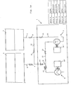
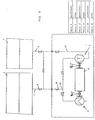
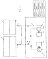
- FIGS. 1 and 1a a compressor 1 with a low pressure stage 2 and a high pressure stage 3 is shown.
- the compressor 1 is connected via a first gas delivery line 4 to a first pipeline section 6 and via a second gas delivery line 5 to a second pipeline section 7.
- a shut-off valve 8 or 9 is provided in the gas delivery lines 4, 5 so that the gas supply or discharge flow can be selectively controlled via the two gas delivery lines 4, 5.
- the two gas delivery lines 4, 5 are connected via a bypass line 10 with each other connected, which also has a shut-off valve, bypass valve 11.
- the two compressor stages, low-pressure compressor stage 2 and high-pressure compressor stage 3, are connected to each other via a compressor line 12, in which also a shut-off valve, compressor valve 13, is provided.
- a compressor line 12 in which also a shut-off valve, compressor valve 13, is provided.
- a screw compressor 2 is provided in the illustrated embodiment and as a high-pressure compressor stage 3 a reciprocating compressor, which in the in Fig. 1 embodiment shown have a common drive unit 14.
- a shiftable clutch 15 or 16 is provided in each case. At the in Fig. 1 shown operating position, the clutch 15 is in an engaged state, so that via the drive unit 14, the low-pressure stage 2 is driven; the clutch 16, however, is in its disengaged position, so that the high-pressure compressor stage 3 is not in operation.
- separate drive units 14 ', 14 may be provided for the low-pressure compressor stage 2 and the high-pressure compressor stage 3 (cf. Fig. 1a ); at the in Fig. 1a shown operating position is - accordingly Fig. 1 - The drive unit 14 'in operation, whereas the drive unit 14''is out of operation.
- a check valve 17 is also provided, which only allows a flow in the direction of the first pipe section 6 and the high-pressure compressor stage 3. Further, from the compressor line 12 between the check valve 17 and the compressor line valve 13, a low-pressure connection line 19 is branched, which opens into the first gas delivery line 4. The low-pressure connection line 19 also has a shut-off valve 20.
- the high-pressure compressor stage 3 is connected on the output side via a high-pressure connection line 21 to the second gas delivery line 5. Also in the high-pressure connection line 21 is a
- the check valves 20, 13, 22 and 11 are changed over, so that the pre-compressed air is passed through the compressor connecting line 12 in the provided as a high-pressure stage 3 reciprocating compressor, in which a High pressure compression of about 100 bar takes place (see. Fig. 2 . 2a ).
- shut-off valves 13, 22, 11 and 8 are switched in their open position, however, the shut-off valve 20 as well as the shut-off valve 9 in the second gas delivery line 5 is closed.
- the screw compressor which is provided as a low-pressure stage 2 sucks air from the environment, which is pre-compressed in the screw compressor and then high-compression in the reciprocating compressor of the high-pressure stage 3; Subsequently, the compressed air is conveyed into the first pipe section 6.
- the highly compressed air from the first pipe section 6 is transferred into the second pipe section 7 (cf. Fig. 3 . 3a ).
- the screw compressor in the low-pressure stage 2 and the reciprocating compressor in the high-pressure stage 3 are in this case decoupled from the drive unit 14 or are the drive units 14, 14 ', 14''still.
- valves 8, 9 are placed in the gas delivery lines 4, 5 and the valve 11 in the bypass line 10 in its open position; the valves 20 in the low-pressure connection line 19 and the valve 22 in the high-pressure connection line 21, however, are in their closed position.
- the highly compressed air flows from the much higher pressure level having pipe section 6 in the second pipe section 7 until in the two pipe sections 6, 7 substantially the same pressure level, for example, about 50 bar adjusts.
- Fig. 4 and 4a can be seen - after the same pressure level has set in the pipe sections 6, 7 - the shut-off valve 11 is closed in the bypass line 10 and the valve 20 in the low pressure connection line 19, the valve 13 in the compressor line 12 and the check valve 22 in the Opened high-pressure connection line 21, so that in the first pipe section 6 still at about 50 bar, for example, precompressed gas in the high-pressure compressor stage 3, which is coupled to the drive unit 14 and the drive unit 14 '' is activated, high pressure is compressed and then over the gas delivery line 5 is conveyed into the second pipe section 7.
- valve 8 in the gas delivery line 4 and the valve 20 in the low-pressure connection line 19 is closed and the screw compressor provided in the low-pressure compressor stage 2 is likewise coupled to the drive unit 14 like the reciprocating compressor of the high-pressure compressor stage 3 (or are both drive units 14 ', 14''inoperation; Fig. 5a ).
- a press several pipe sections 6, 7.
- the introduced into the second pipe section 7 compressed air may optionally be used in the manner described above for pushing a further pipe section.
- the opening or closing of the shut-off valves 8, 9, 11, 13, 20, 22 can be done either manually or automatically controlled or regulated. It is merely essential to the invention that at least two pipe sections, in particular a pipeline, can be pressed in a more energy-efficient manner by means of the abovementioned method or the device mentioned above in comparison with known systems.
Landscapes
- Engineering & Computer Science (AREA)
- Mechanical Engineering (AREA)
- General Engineering & Computer Science (AREA)
- Compressors, Vaccum Pumps And Other Relevant Systems (AREA)
- Pipeline Systems (AREA)
Priority Applications (1)
| Application Number | Priority Date | Filing Date | Title |
|---|---|---|---|
| PL09753311T PL2300713T3 (pl) | 2008-05-28 | 2009-05-25 | Sposób i urządzenie do transportu sprężonego gazu |
Applications Claiming Priority (2)
| Application Number | Priority Date | Filing Date | Title |
|---|---|---|---|
| AT0085408A AT506905B1 (de) | 2008-05-28 | 2008-05-28 | Verfahren und vorrichtung zum fördern von gas |
| PCT/AT2009/000217 WO2009143547A1 (de) | 2008-05-28 | 2009-05-25 | Verfahren und vorrichtung zum fördern von verdichtetem gas |
Publications (2)
| Publication Number | Publication Date |
|---|---|
| EP2300713A1 EP2300713A1 (de) | 2011-03-30 |
| EP2300713B1 true EP2300713B1 (de) | 2012-04-25 |
Family
ID=40875020
Family Applications (1)
| Application Number | Title | Priority Date | Filing Date |
|---|---|---|---|
| EP09753311A Active EP2300713B1 (de) | 2008-05-28 | 2009-05-25 | Verfahren und vorrichtung zum fördern von verdichtetem gas |
Country Status (6)
| Country | Link |
|---|---|
| EP (1) | EP2300713B1 (pl) |
| CN (1) | CN102046971B (pl) |
| AT (2) | AT506905B1 (pl) |
| EA (1) | EA017921B1 (pl) |
| PL (1) | PL2300713T3 (pl) |
| WO (1) | WO2009143547A1 (pl) |
Families Citing this family (4)
| Publication number | Priority date | Publication date | Assignee | Title |
|---|---|---|---|---|
| KR102219870B1 (ko) * | 2019-04-04 | 2021-02-24 | 지에스건설 주식회사 | 증발가스 압축 설비 |
| CN110094188B (zh) * | 2019-04-09 | 2021-06-01 | 中国石油天然气集团有限公司 | 一种超临界二氧化碳压缩系统的分级调压系统及其方法 |
| EP4326988A1 (en) * | 2021-06-24 | 2024-02-28 | Apple Inc. | Shared compressor |
| US12019460B2 (en) | 2021-06-24 | 2024-06-25 | Apple Inc. | Shared compressor |
Family Cites Families (4)
| Publication number | Priority date | Publication date | Assignee | Title |
|---|---|---|---|---|
| US2218565A (en) * | 1937-05-01 | 1940-10-22 | Vickers Inc | Compound positive displacement pump circuit |
| SE369948B (pl) * | 1969-12-03 | 1974-09-23 | I Soeyland | |
| US4526513A (en) * | 1980-07-18 | 1985-07-02 | Acco Industries Inc. | Method and apparatus for control of pipeline compressors |
| US5577390A (en) * | 1994-11-14 | 1996-11-26 | Carrier Corporation | Compressor for single or multi-stage operation |
-
2008
- 2008-05-28 AT AT0085408A patent/AT506905B1/de active
-
2009
- 2009-05-25 EP EP09753311A patent/EP2300713B1/de active Active
- 2009-05-25 WO PCT/AT2009/000217 patent/WO2009143547A1/de not_active Ceased
- 2009-05-25 EA EA201071383A patent/EA017921B1/ru unknown
- 2009-05-25 CN CN2009801194660A patent/CN102046971B/zh active Active
- 2009-05-25 PL PL09753311T patent/PL2300713T3/pl unknown
- 2009-05-25 AT AT09753311T patent/ATE555307T1/de active
Also Published As
| Publication number | Publication date |
|---|---|
| EA201071383A1 (ru) | 2011-04-29 |
| AT506905B1 (de) | 2011-03-15 |
| WO2009143547A1 (de) | 2009-12-03 |
| PL2300713T3 (pl) | 2012-10-31 |
| ATE555307T1 (de) | 2012-05-15 |
| AT506905A1 (de) | 2009-12-15 |
| EP2300713A1 (de) | 2011-03-30 |
| EA017921B1 (ru) | 2013-04-30 |
| CN102046971B (zh) | 2013-09-11 |
| CN102046971A (zh) | 2011-05-04 |
Similar Documents
| Publication | Publication Date | Title |
|---|---|---|
| EP1963686B1 (de) | Hydrostatischer antrieb | |
| EP0752531A1 (de) | Vorrichtung zum raschen Evakuieren einer Vakuumkammer | |
| DE112007000125B4 (de) | Hochdruck-Kompressor sowie dessen Verwendung und Verfahren zu dessen Betrieb | |
| DE102014209856A1 (de) | Hydraulische Versorgungsvorrichtung | |
| DE102015009013A1 (de) | Gasleitungsentleerungssystem und -verfahren | |
| AT506905B1 (de) | Verfahren und vorrichtung zum fördern von gas | |
| EP3271121B1 (de) | Vorrichtung und verfahren zum schneiden eines schneidguts mit hilfe eines fluids | |
| DE102011082645A1 (de) | Niederdruckkreislauf für ein Kraftstoffeinspritzsystem sowie Kraftstoffeinspritzsystem | |
| EP1964743B1 (de) | Druckluftversorgungseinrichtung für ein nutzfahrzeug und verfahren zum betreiben einer druckluftversorgungseinrichtung | |
| DE102015007731A1 (de) | Verfahren zum Verdichten eines Gases, Recheneinheit und mehrstufiger Kolbenverdichter | |
| DE3942105C1 (pl) | ||
| DE102006037174A1 (de) | Vorrichtung und Verfahren zur Regelung eines Kraftstoffvolumenstroms in einem Niederdruckkreislaufsystem für eine Verbrennungskraftmaschine | |
| DE102010006170A1 (de) | Spülvorrichtung | |
| DE102005060992A1 (de) | Hydrostatischer Antrieb mit Rückgewinnug von Bremsenergie | |
| DE102012212892B4 (de) | Einspritzeinrichtung für eine Verbrennungskraftmaschine | |
| DE102020121963A1 (de) | Kompressorsystem | |
| DE102020200611A1 (de) | Brennstoffzellensystem | |
| DE102005004147A1 (de) | Handhabungsvorrichtung zum Lösen und/oder Anschließen von insbesondere elastischen Rohren von/an Steckanschlusseinrichtungen | |
| DE102013008540A1 (de) | Mehrstufiger Luftpresser für eine Druckluftanlage, insbesondere für eine Druckluftbremsanlage eines Nutzfahrzeugs | |
| DE102010055125A1 (de) | Vakuumpumpe, insbesondere für einen Bremskraftverstärker | |
| DE202005006719U1 (de) | Pumpvorrichtung | |
| EP1843040A2 (de) | Verfahren zum Betreiben einer oszillierenden Verdrängerpumpe und oszillierende Verdrängerpumpe | |
| DE102018126940A1 (de) | System mit einem pneumatisch betriebenen Hydraulikwerkzeug, Abschaltventil sowie Wagen für ein pneumatisch betriebenes Hydraulikwerkzeug | |
| CH655862A5 (de) | Verfahren zur beschleunigung des luftaustausches beim befuellen oder entleeren eines druckraumes und vorrichtung zur durchfuehrung desselben. | |
| DE9101097U1 (de) | Mechanische entsperrbare Fluidkupplung für Mehrwegbehältnisse mit äußerer Zwangsbelüftung zum Transport, Lagerung und Entnahme von Fluiden sowie zum Anschluß und zur Absicherung eines Fluidsystems |
Legal Events
| Date | Code | Title | Description |
|---|---|---|---|
| PUAI | Public reference made under article 153(3) epc to a published international application that has entered the european phase |
Free format text: ORIGINAL CODE: 0009012 |
|
| 17P | Request for examination filed |
Effective date: 20101117 |
|
| AK | Designated contracting states |
Kind code of ref document: A1 Designated state(s): AT BE BG CH CY CZ DE DK EE ES FI FR GB GR HR HU IE IS IT LI LT LU LV MC MK MT NL NO PL PT RO SE SI SK TR |
|
| AX | Request for extension of the european patent |
Extension state: AL BA RS |
|
| DAX | Request for extension of the european patent (deleted) | ||
| GRAP | Despatch of communication of intention to grant a patent |
Free format text: ORIGINAL CODE: EPIDOSNIGR1 |
|
| GRAS | Grant fee paid |
Free format text: ORIGINAL CODE: EPIDOSNIGR3 |
|
| GRAA | (expected) grant |
Free format text: ORIGINAL CODE: 0009210 |
|
| AK | Designated contracting states |
Kind code of ref document: B1 Designated state(s): AT BE BG CH CY CZ DE DK EE ES FI FR GB GR HR HU IE IS IT LI LT LU LV MC MK MT NL NO PL PT RO SE SI SK TR |
|
| REG | Reference to a national code |
Ref country code: GB Ref legal event code: FG4D Free format text: NOT ENGLISH |
|
| REG | Reference to a national code |
Ref country code: CH Ref legal event code: EP |
|
| REG | Reference to a national code |
Ref country code: AT Ref legal event code: REF Ref document number: 555307 Country of ref document: AT Kind code of ref document: T Effective date: 20120515 |
|
| REG | Reference to a national code |
Ref country code: IE Ref legal event code: FG4D Free format text: LANGUAGE OF EP DOCUMENT: GERMAN |
|
| REG | Reference to a national code |
Ref country code: DE Ref legal event code: R096 Ref document number: 502009003388 Country of ref document: DE Effective date: 20120621 |
|
| REG | Reference to a national code |
Ref country code: RO Ref legal event code: EPE |
|
| REG | Reference to a national code |
Ref country code: NL Ref legal event code: T3 |
|
| REG | Reference to a national code |
Ref country code: SK Ref legal event code: T3 Ref document number: E 12041 Country of ref document: SK |
|
| LTIE | Lt: invalidation of european patent or patent extension |
Effective date: 20120425 |
|
| PG25 | Lapsed in a contracting state [announced via postgrant information from national office to epo] |
Ref country code: LT Free format text: LAPSE BECAUSE OF FAILURE TO SUBMIT A TRANSLATION OF THE DESCRIPTION OR TO PAY THE FEE WITHIN THE PRESCRIBED TIME-LIMIT Effective date: 20120425 Ref country code: NO Free format text: LAPSE BECAUSE OF FAILURE TO SUBMIT A TRANSLATION OF THE DESCRIPTION OR TO PAY THE FEE WITHIN THE PRESCRIBED TIME-LIMIT Effective date: 20120725 Ref country code: FI Free format text: LAPSE BECAUSE OF FAILURE TO SUBMIT A TRANSLATION OF THE DESCRIPTION OR TO PAY THE FEE WITHIN THE PRESCRIBED TIME-LIMIT Effective date: 20120425 Ref country code: IS Free format text: LAPSE BECAUSE OF FAILURE TO SUBMIT A TRANSLATION OF THE DESCRIPTION OR TO PAY THE FEE WITHIN THE PRESCRIBED TIME-LIMIT Effective date: 20120825 Ref country code: CY Free format text: LAPSE BECAUSE OF FAILURE TO SUBMIT A TRANSLATION OF THE DESCRIPTION OR TO PAY THE FEE WITHIN THE PRESCRIBED TIME-LIMIT Effective date: 20120425 Ref country code: SE Free format text: LAPSE BECAUSE OF FAILURE TO SUBMIT A TRANSLATION OF THE DESCRIPTION OR TO PAY THE FEE WITHIN THE PRESCRIBED TIME-LIMIT Effective date: 20120425 |
|
| REG | Reference to a national code |
Ref country code: PL Ref legal event code: T3 |
|
| BERE | Be: lapsed |
Owner name: LEOBERSDORFER MASCHINENFABRIK GMBH&CO.KG Effective date: 20120531 |
|
| PG25 | Lapsed in a contracting state [announced via postgrant information from national office to epo] |
Ref country code: HR Free format text: LAPSE BECAUSE OF FAILURE TO SUBMIT A TRANSLATION OF THE DESCRIPTION OR TO PAY THE FEE WITHIN THE PRESCRIBED TIME-LIMIT Effective date: 20120425 Ref country code: SI Free format text: LAPSE BECAUSE OF FAILURE TO SUBMIT A TRANSLATION OF THE DESCRIPTION OR TO PAY THE FEE WITHIN THE PRESCRIBED TIME-LIMIT Effective date: 20120425 Ref country code: LV Free format text: LAPSE BECAUSE OF FAILURE TO SUBMIT A TRANSLATION OF THE DESCRIPTION OR TO PAY THE FEE WITHIN THE PRESCRIBED TIME-LIMIT Effective date: 20120425 Ref country code: GR Free format text: LAPSE BECAUSE OF FAILURE TO SUBMIT A TRANSLATION OF THE DESCRIPTION OR TO PAY THE FEE WITHIN THE PRESCRIBED TIME-LIMIT Effective date: 20120726 Ref country code: PT Free format text: LAPSE BECAUSE OF FAILURE TO SUBMIT A TRANSLATION OF THE DESCRIPTION OR TO PAY THE FEE WITHIN THE PRESCRIBED TIME-LIMIT Effective date: 20120827 |
|
| PG25 | Lapsed in a contracting state [announced via postgrant information from national office to epo] |
Ref country code: MC Free format text: LAPSE BECAUSE OF NON-PAYMENT OF DUE FEES Effective date: 20120531 |
|
| PG25 | Lapsed in a contracting state [announced via postgrant information from national office to epo] |
Ref country code: EE Free format text: LAPSE BECAUSE OF FAILURE TO SUBMIT A TRANSLATION OF THE DESCRIPTION OR TO PAY THE FEE WITHIN THE PRESCRIBED TIME-LIMIT Effective date: 20120425 Ref country code: DK Free format text: LAPSE BECAUSE OF FAILURE TO SUBMIT A TRANSLATION OF THE DESCRIPTION OR TO PAY THE FEE WITHIN THE PRESCRIBED TIME-LIMIT Effective date: 20120425 |
|
| REG | Reference to a national code |
Ref country code: IE Ref legal event code: MM4A |
|
| PG25 | Lapsed in a contracting state [announced via postgrant information from national office to epo] |
Ref country code: BE Free format text: LAPSE BECAUSE OF NON-PAYMENT OF DUE FEES Effective date: 20120531 Ref country code: MK Free format text: LAPSE BECAUSE OF FAILURE TO SUBMIT A TRANSLATION OF THE DESCRIPTION OR TO PAY THE FEE WITHIN THE PRESCRIBED TIME-LIMIT Effective date: 20120425 |
|
| PLBE | No opposition filed within time limit |
Free format text: ORIGINAL CODE: 0009261 |
|
| STAA | Information on the status of an ep patent application or granted ep patent |
Free format text: STATUS: NO OPPOSITION FILED WITHIN TIME LIMIT |
|
| 26N | No opposition filed |
Effective date: 20130128 |
|
| PG25 | Lapsed in a contracting state [announced via postgrant information from national office to epo] |
Ref country code: ES Free format text: LAPSE BECAUSE OF FAILURE TO SUBMIT A TRANSLATION OF THE DESCRIPTION OR TO PAY THE FEE WITHIN THE PRESCRIBED TIME-LIMIT Effective date: 20120805 Ref country code: IE Free format text: LAPSE BECAUSE OF NON-PAYMENT OF DUE FEES Effective date: 20120525 |
|
| REG | Reference to a national code |
Ref country code: DE Ref legal event code: R097 Ref document number: 502009003388 Country of ref document: DE Effective date: 20130128 |
|
| PG25 | Lapsed in a contracting state [announced via postgrant information from national office to epo] |
Ref country code: MT Free format text: LAPSE BECAUSE OF FAILURE TO SUBMIT A TRANSLATION OF THE DESCRIPTION OR TO PAY THE FEE WITHIN THE PRESCRIBED TIME-LIMIT Effective date: 20120425 Ref country code: BG Free format text: LAPSE BECAUSE OF FAILURE TO SUBMIT A TRANSLATION OF THE DESCRIPTION OR TO PAY THE FEE WITHIN THE PRESCRIBED TIME-LIMIT Effective date: 20120725 |
|
| REG | Reference to a national code |
Ref country code: CH Ref legal event code: PL |
|
| PG25 | Lapsed in a contracting state [announced via postgrant information from national office to epo] |
Ref country code: CH Free format text: LAPSE BECAUSE OF NON-PAYMENT OF DUE FEES Effective date: 20130531 Ref country code: LI Free format text: LAPSE BECAUSE OF NON-PAYMENT OF DUE FEES Effective date: 20130531 |
|
| PG25 | Lapsed in a contracting state [announced via postgrant information from national office to epo] |
Ref country code: TR Free format text: LAPSE BECAUSE OF FAILURE TO SUBMIT A TRANSLATION OF THE DESCRIPTION OR TO PAY THE FEE WITHIN THE PRESCRIBED TIME-LIMIT Effective date: 20120425 |
|
| PG25 | Lapsed in a contracting state [announced via postgrant information from national office to epo] |
Ref country code: LU Free format text: LAPSE BECAUSE OF NON-PAYMENT OF DUE FEES Effective date: 20120525 |
|
| PG25 | Lapsed in a contracting state [announced via postgrant information from national office to epo] |
Ref country code: HU Free format text: LAPSE BECAUSE OF FAILURE TO SUBMIT A TRANSLATION OF THE DESCRIPTION OR TO PAY THE FEE WITHIN THE PRESCRIBED TIME-LIMIT Effective date: 20090525 |
|
| REG | Reference to a national code |
Ref country code: FR Ref legal event code: PLFP Year of fee payment: 8 |
|
| REG | Reference to a national code |
Ref country code: FR Ref legal event code: PLFP Year of fee payment: 9 |
|
| REG | Reference to a national code |
Ref country code: FR Ref legal event code: PLFP Year of fee payment: 10 |
|
| P01 | Opt-out of the competence of the unified patent court (upc) registered |
Effective date: 20230519 |
|
| PGFP | Annual fee paid to national office [announced via postgrant information from national office to epo] |
Ref country code: SK Payment date: 20250313 Year of fee payment: 17 |
|
| PGFP | Annual fee paid to national office [announced via postgrant information from national office to epo] |
Ref country code: NL Payment date: 20250401 Year of fee payment: 17 |
|
| PGFP | Annual fee paid to national office [announced via postgrant information from national office to epo] |
Ref country code: DE Payment date: 20250528 Year of fee payment: 17 |
|
| PGFP | Annual fee paid to national office [announced via postgrant information from national office to epo] |
Ref country code: GB Payment date: 20250523 Year of fee payment: 17 |
|
| PGFP | Annual fee paid to national office [announced via postgrant information from national office to epo] |
Ref country code: IT Payment date: 20250424 Year of fee payment: 17 |
|
| PGFP | Annual fee paid to national office [announced via postgrant information from national office to epo] |
Ref country code: FR Payment date: 20250414 Year of fee payment: 17 |
|
| PGFP | Annual fee paid to national office [announced via postgrant information from national office to epo] |
Ref country code: AT Payment date: 20250508 Year of fee payment: 17 Ref country code: RO Payment date: 20250522 Year of fee payment: 17 |
|
| PGFP | Annual fee paid to national office [announced via postgrant information from national office to epo] |
Ref country code: CZ Payment date: 20250411 Year of fee payment: 17 |
|
| PGFP | Annual fee paid to national office [announced via postgrant information from national office to epo] |
Ref country code: PL Payment date: 20260319 Year of fee payment: 18 |