EP2300217B1 - Resonant nodal mount for linear ultrasonic horns - Google Patents
Resonant nodal mount for linear ultrasonic horns Download PDFInfo
- Publication number
- EP2300217B1 EP2300217B1 EP09747595.8A EP09747595A EP2300217B1 EP 2300217 B1 EP2300217 B1 EP 2300217B1 EP 09747595 A EP09747595 A EP 09747595A EP 2300217 B1 EP2300217 B1 EP 2300217B1
- Authority
- EP
- European Patent Office
- Prior art keywords
- mount
- horn
- bearing surface
- flange
- predetermined frequency
- Prior art date
- Legal status (The legal status is an assumption and is not a legal conclusion. Google has not performed a legal analysis and makes no representation as to the accuracy of the status listed.)
- Not-in-force
Links
- 238000006073 displacement reaction Methods 0.000 claims description 12
- 238000000034 method Methods 0.000 claims description 3
- 238000003466 welding Methods 0.000 description 21
- 238000012360 testing method Methods 0.000 description 6
- 238000002474 experimental method Methods 0.000 description 5
- 229910000883 Ti6Al4V Inorganic materials 0.000 description 2
- 230000000052 comparative effect Effects 0.000 description 2
- 239000000463 material Substances 0.000 description 2
- 239000007787 solid Substances 0.000 description 2
- 238000012800 visualization Methods 0.000 description 2
- 229910045601 alloy Inorganic materials 0.000 description 1
- 239000000956 alloy Substances 0.000 description 1
- 238000001816 cooling Methods 0.000 description 1
- 239000004744 fabric Substances 0.000 description 1
- 238000004519 manufacturing process Methods 0.000 description 1
- 238000012545 processing Methods 0.000 description 1
- 238000007789 sealing Methods 0.000 description 1
- 238000005493 welding type Methods 0.000 description 1
Images


Classifications
-
- B—PERFORMING OPERATIONS; TRANSPORTING
- B29—WORKING OF PLASTICS; WORKING OF SUBSTANCES IN A PLASTIC STATE IN GENERAL
- B29C—SHAPING OR JOINING OF PLASTICS; SHAPING OF MATERIAL IN A PLASTIC STATE, NOT OTHERWISE PROVIDED FOR; AFTER-TREATMENT OF THE SHAPED PRODUCTS, e.g. REPAIRING
- B29C65/00—Joining or sealing of preformed parts, e.g. welding of plastics materials; Apparatus therefor
- B29C65/02—Joining or sealing of preformed parts, e.g. welding of plastics materials; Apparatus therefor by heating, with or without pressure
- B29C65/08—Joining or sealing of preformed parts, e.g. welding of plastics materials; Apparatus therefor by heating, with or without pressure using ultrasonic vibrations
-
- B—PERFORMING OPERATIONS; TRANSPORTING
- B29—WORKING OF PLASTICS; WORKING OF SUBSTANCES IN A PLASTIC STATE IN GENERAL
- B29C—SHAPING OR JOINING OF PLASTICS; SHAPING OF MATERIAL IN A PLASTIC STATE, NOT OTHERWISE PROVIDED FOR; AFTER-TREATMENT OF THE SHAPED PRODUCTS, e.g. REPAIRING
- B29C66/00—General aspects of processes or apparatus for joining preformed parts
- B29C66/80—General aspects of machine operations or constructions and parts thereof
- B29C66/81—General aspects of the pressing elements, i.e. the elements applying pressure on the parts to be joined in the area to be joined, e.g. the welding jaws or clamps
- B29C66/816—General aspects of the pressing elements, i.e. the elements applying pressure on the parts to be joined in the area to be joined, e.g. the welding jaws or clamps characterised by the mounting of the pressing elements, e.g. of the welding jaws or clamps
-
- B—PERFORMING OPERATIONS; TRANSPORTING
- B29—WORKING OF PLASTICS; WORKING OF SUBSTANCES IN A PLASTIC STATE IN GENERAL
- B29C—SHAPING OR JOINING OF PLASTICS; SHAPING OF MATERIAL IN A PLASTIC STATE, NOT OTHERWISE PROVIDED FOR; AFTER-TREATMENT OF THE SHAPED PRODUCTS, e.g. REPAIRING
- B29C66/00—General aspects of processes or apparatus for joining preformed parts
- B29C66/90—Measuring or controlling the joining process
- B29C66/95—Measuring or controlling the joining process by measuring or controlling specific variables not covered by groups B29C66/91 - B29C66/94
- B29C66/951—Measuring or controlling the joining process by measuring or controlling specific variables not covered by groups B29C66/91 - B29C66/94 by measuring or controlling the vibration frequency and/or the vibration amplitude of vibrating joining tools, e.g. of ultrasonic welding tools
- B29C66/9512—Measuring or controlling the joining process by measuring or controlling specific variables not covered by groups B29C66/91 - B29C66/94 by measuring or controlling the vibration frequency and/or the vibration amplitude of vibrating joining tools, e.g. of ultrasonic welding tools by controlling their vibration frequency
-
- B—PERFORMING OPERATIONS; TRANSPORTING
- B29—WORKING OF PLASTICS; WORKING OF SUBSTANCES IN A PLASTIC STATE IN GENERAL
- B29C—SHAPING OR JOINING OF PLASTICS; SHAPING OF MATERIAL IN A PLASTIC STATE, NOT OTHERWISE PROVIDED FOR; AFTER-TREATMENT OF THE SHAPED PRODUCTS, e.g. REPAIRING
- B29C66/00—General aspects of processes or apparatus for joining preformed parts
- B29C66/90—Measuring or controlling the joining process
- B29C66/95—Measuring or controlling the joining process by measuring or controlling specific variables not covered by groups B29C66/91 - B29C66/94
- B29C66/951—Measuring or controlling the joining process by measuring or controlling specific variables not covered by groups B29C66/91 - B29C66/94 by measuring or controlling the vibration frequency and/or the vibration amplitude of vibrating joining tools, e.g. of ultrasonic welding tools
- B29C66/9513—Measuring or controlling the joining process by measuring or controlling specific variables not covered by groups B29C66/91 - B29C66/94 by measuring or controlling the vibration frequency and/or the vibration amplitude of vibrating joining tools, e.g. of ultrasonic welding tools characterised by specific vibration frequency values or ranges
Definitions
- the present invention relates to ultrasonic welding mounts, and particularly to a mount for a linear ultrasonic horn having a predetermined resonant frequency with a mount having about the same resonant frequency.
- Ultrasonic welding is typically used to join multiple parts together using vibrations converted into heat energy.
- Common types of ultrasonic welding are plunge and continuous welding.
- plunge welding an ultrasonic horn plunges (travels towards the parts) and transmits vibrations into a top part.
- continuous welding for example scan or rotary welding, the ultrasonic horn is typically stationary or rotating and the part is moved beneath it.
- Continuous ultrasonic welding is typically used for sealing fabrics, films, and other parts.
- Each of the ultrasonic welding types involves a horn.
- Ultrasonic horns impart energy to the parts to be welded at a selected wavelength, frequency, and amplitude.
- the horn resonates at the frequency of the ultrasonic transducer energizing it; transducers having a frequency of about 20,000 Hertz being perhaps the most commonly available commercially.
- a rotary horn typically includes a shaft with input and output ends, and a welding portion mounted on and coaxial with the output end.
- the diameter of the welding portion is typically greater than the diameter of the shaft.
- the welding portion has a cylindrical weld face having a diameter that expands and contracts with the application of vibration energy.
- a rotary horn is cylindrical and rotates about a longitudinal axis.
- the input vibration is in the axial direction and the output vibration is in the radial direction.
- the horn and anvil are conveniently mounted close to each other, and the anvil can rotate in the opposite direction of the horn.
- the part (or parts) to be welded passes between the cylindrical surfaces at a linear velocity, equal to the tangential velocity of the cylindrical surfaces.
- a node is a position of the horn that has zero displacement in one or more directions.
- a node is a point or region on an ultrasonic horn where the longitudinal displacement is negligible or zero and the radial displacement is at or near its maximum when the horn is in resonance.
- An anti-node is a point or region where the longitudinal displacement is at or near its maximum and the radial displacement is at or near its minimum.
- U.S. Patent 6,786,384 discloses an effective mount for a rotary ultrasonic horn having a predetermined resonant frequency.
- the disclosed mount has itself about the same resonant frequency such that the mount is driven by the horn it is holding in such a way that the radial displacement imparted by the horn to the mount is dissipated such that an outer bearing surface is left largely unmoving (in a radial sense, during operation it is rotating circumferentially).
- U.S. Pat. No. 3,529,660 reports a solid horn as used for sonic or ultrasonic processing, such as welding, is provided with gas cooling means which include a central longitudinal bore, a plurality of radial gas escape holes, and a shroud for directing the gas flow along the horn.
- the disclosure describes a system for ultrasonic manufacturing having a horn having a resonance at a predetermined frequency, and a mount for that horn.
- the mount includes a contacting portion having an inner bearing surface that is used for actually contacting the horn.
- a flange extends outwardly from the connecting shaft, ending in an outer perimeter.
- An annular mounting portion is attached to the flange between the contacting portion and the outer perimeter.
- the mount is constructed such that the mount has a resonance at about the predetermined frequency, and in operation the contacting portion of the mount is coupled to the horn at a point where the horn has a node at said predetermined frequency.
- Mount 10 is a solid of revolution having the depicted cross-section.
- Mount 10 includes contacting portion 12 having an inner bearing surface 14.
- Contacting portion 12 may optionally have a bore 16.
- Flange 18 extends outwardly from contacting portion 12, ending in an outer perimeter 20.
- An annular mounting portion 22 is attached to the flange 18 between the contacting portion 12 and the outer perimeter 20.
- the end of the annular mounting portion 22 opposite flange 18 is outer bearing surface 24.
- an annular counterweight 26 is mounted on the flange 18 adjacent the perimeter 20.
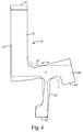
- FIG. 2 a cross-section perspective view of a welding system incorporating several of the mounts according to FIG. 1 is illustrated.
- the mounts 10 support linear horn 30.
- Linear horn 30 has a welding surface 32 against which, for example, sheet material is passed for scan welding.
- Linear horn 30 in one embodiment is energized by an ultrasonic transducer acting at an end 34.
- the mounts 10 contact linear horn 30 at points that are nodes 36 when the horn is energized at a predetermined frequency.
- Mount 10 is constructed such that the mount has a resonance at about that predetermined frequency.
- FIG. 3 a cross-section perspective view of the welding system of FIG. 2 being supported by clamping bars is illustrated.
- Clamping bars 40 and 42 compress the mount-and-horn assembly so that is can be supported effectively within, for example a webhandling line conveying the material needing to be welded.
- Shallow counterbores 44 may be present for receiving the mounting portion 22 of the mounts 10.
- FIG. 4 an overlapping comparative visualization of a typical cross section of the mount 10 at the limits of motion imparted when the mount is resonating at the predetermined frequency is illustrated.
- the mount 10 in its unstressed configuration is shown in phantom lines; its maximally stressed configuration (when the lateral expansion of the vibrating linear horn 30 is greatest) is shown in solid lines. It is to be noted how much smaller the displacement from the unstressed condition exhibited by the outer bearing surface 24 compared to the interior bearing surface. With such small displacements at the outer bearing surface 24, the mount can be successfully held by the clamping bar 40 (seen in FIG. 3 ).
- FIG. 1 Several mounts generally as depicted in FIG. 1 were machined from titanium 6Al 4V alloy. A typical linear horn 22.9 cm wide and designed to resonate near 20,000 Hertz was also fabricated from titanium 6Al 4V was used for this test. An ultrasonic transducer, commercially available from Branson Ultrasonics Corporation of Danbury, CT was attached at one end of a conventional booster that in turn was mounted to the linear horn. This arrangement was used to energize the horn during three experiments.
- the horn was unclamped in order to provide a control value for the amount of power drawn by the set up.
- the power output on the ultrasonic power supply was set to 100%.
- the horn was mounted using four of the mounts, each pressed against a vibration node, between a pair of clamping bars generally as depicted in FIG. 3 .
- the power output on the ultrasonic power supply was set to 50%.
- the third experiment was similar to the second, except that the power setting was again set to 100%, just as for the first experiment.
- the conditions and results are summarized in Table 1.
Landscapes
- Engineering & Computer Science (AREA)
- Mechanical Engineering (AREA)
- Apparatuses For Generation Of Mechanical Vibrations (AREA)
- Lining Or Joining Of Plastics Or The Like (AREA)
- Pressure Welding/Diffusion-Bonding (AREA)
Applications Claiming Priority (2)
| Application Number | Priority Date | Filing Date | Title |
|---|---|---|---|
| US12/121,304 US7718022B2 (en) | 2008-05-15 | 2008-05-15 | Resonant nodal mount for linear ultrasonic horns |
| PCT/US2009/043979 WO2009140513A1 (en) | 2008-05-15 | 2009-05-14 | Resonant nodal mount for linear ultrasonic horns |
Publications (2)
| Publication Number | Publication Date |
|---|---|
| EP2300217A1 EP2300217A1 (en) | 2011-03-30 |
| EP2300217B1 true EP2300217B1 (en) | 2016-11-02 |
Family
ID=40996587
Family Applications (1)
| Application Number | Title | Priority Date | Filing Date |
|---|---|---|---|
| EP09747595.8A Not-in-force EP2300217B1 (en) | 2008-05-15 | 2009-05-14 | Resonant nodal mount for linear ultrasonic horns |
Country Status (7)
| Country | Link |
|---|---|
| US (1) | US7718022B2 (enExample) |
| EP (1) | EP2300217B1 (enExample) |
| JP (1) | JP2011523374A (enExample) |
| KR (1) | KR101577088B1 (enExample) |
| CN (1) | CN102026796B (enExample) |
| BR (1) | BRPI0908677A2 (enExample) |
| WO (1) | WO2009140513A1 (enExample) |
Families Citing this family (10)
| Publication number | Priority date | Publication date | Assignee | Title |
|---|---|---|---|---|
| JP4138850B1 (ja) * | 2007-07-24 | 2008-08-27 | 伊藤 仁彦 | 超音波振動接合装置 |
| DE102010041432A1 (de) | 2010-09-27 | 2012-03-29 | Robert Bosch Gmbh | Ultraschallschwingeinheit |
| EP2789450A1 (de) | 2013-04-09 | 2014-10-15 | Telsonic Holding AG | Vorrichtung zum Verschweissen mittels Ultraschall |
| US9938033B2 (en) * | 2016-04-18 | 2018-04-10 | Edison Welding Institute, Inc. | Sonotrode |
| DE102016117689B4 (de) | 2016-09-20 | 2020-10-22 | Sonotronic Nagel Gmbh | Sonotrodeneinheit sowie Verfahren zu ihrer Herstellung |
| DE102017117078B4 (de) * | 2017-07-28 | 2019-06-13 | Schunk Sonosystems Gmbh | Sonotrode sowie Verfahren zur Beeinflussung des Schwingungsverhaltens einer Sonotrode |
| DE102018132837A1 (de) * | 2018-12-19 | 2020-06-25 | Herrmann Ultraschalltechnik Gmbh & Co. Kg | Ultraschallschweißanlage |
| CH716161A1 (fr) * | 2019-05-08 | 2020-11-13 | Roten Maxime | Outil vibrant et ensemble vibrant, système vibratoire, agencement, dispositif avec roulement à billes et diverses machines comprenant un tel outil. |
| EP4000751A1 (fr) | 2020-11-11 | 2022-05-25 | Roten, Maxime | Outil vibrant et système vibratoire comprenant un tel outil |
| US20240100623A1 (en) * | 2022-09-27 | 2024-03-28 | Agile Ultrasonics Corp | Ultrasonic sonotrode for use in welding complex geometries |
Family Cites Families (7)
| Publication number | Priority date | Publication date | Assignee | Title |
|---|---|---|---|---|
| US3529660A (en) | 1968-11-20 | 1970-09-22 | Branson Instr | Solid horn with cooling means |
| US4647336A (en) | 1985-03-08 | 1987-03-03 | Kimberly-Clark Corporation | Rebuildable support assembly |
| JP3128715B2 (ja) * | 1992-12-24 | 2001-01-29 | 株式会社新川 | ボンデイング装置 |
| CN2328508Y (zh) * | 1997-12-24 | 1999-07-14 | 强荣超音波机械有限公司 | 超声波熔接机 |
| CN2464534Y (zh) * | 2001-02-02 | 2001-12-12 | 陈健仁 | 超声波熔接机 |
| US6786384B1 (en) | 2003-06-13 | 2004-09-07 | 3M Innovative Properties Company | Ultrasonic horn mount |
| CN2801369Y (zh) * | 2004-11-06 | 2006-08-02 | 罗琳 | 超声波焊线机焊头运动驱动装置 |
-
2008
- 2008-05-15 US US12/121,304 patent/US7718022B2/en not_active Expired - Fee Related
-
2009
- 2009-05-14 JP JP2011509707A patent/JP2011523374A/ja not_active Withdrawn
- 2009-05-14 KR KR1020107027484A patent/KR101577088B1/ko not_active Expired - Fee Related
- 2009-05-14 BR BRPI0908677-3A patent/BRPI0908677A2/pt not_active Application Discontinuation
- 2009-05-14 CN CN200980117367.9A patent/CN102026796B/zh not_active Expired - Fee Related
- 2009-05-14 EP EP09747595.8A patent/EP2300217B1/en not_active Not-in-force
- 2009-05-14 WO PCT/US2009/043979 patent/WO2009140513A1/en not_active Ceased
Also Published As
| Publication number | Publication date |
|---|---|
| KR20110021858A (ko) | 2011-03-04 |
| CN102026796A (zh) | 2011-04-20 |
| BRPI0908677A2 (pt) | 2020-08-18 |
| WO2009140513A1 (en) | 2009-11-19 |
| CN102026796B (zh) | 2016-04-20 |
| EP2300217A1 (en) | 2011-03-30 |
| US20090283570A1 (en) | 2009-11-19 |
| KR101577088B1 (ko) | 2015-12-11 |
| US7718022B2 (en) | 2010-05-18 |
| JP2011523374A (ja) | 2011-08-11 |
Similar Documents
| Publication | Publication Date | Title |
|---|---|---|
| EP2300217B1 (en) | Resonant nodal mount for linear ultrasonic horns | |
| KR100562246B1 (ko) | 음향 혼을 위한 비절점 장착 시스템 | |
| JP4050469B2 (ja) | 回転音響ホーン | |
| JP4116570B2 (ja) | 振動要素のための装着システム及び装着システムを形成するための方法 | |
| EP1455955B1 (en) | Rigid isolation of rotary ultrasonic horn | |
| EP1633497B1 (en) | Ultrasonic horn mount | |
| US7754141B2 (en) | Bi-material ultrasonic horn with integral isolation member | |
| MXPA04005252A (es) | Cuerno ultrasonico giratorio de aislante rigido. | |
| MXPA01002815A (en) | Rotary acoustic horn with sleeve |
Legal Events
| Date | Code | Title | Description |
|---|---|---|---|
| PUAI | Public reference made under article 153(3) epc to a published international application that has entered the european phase |
Free format text: ORIGINAL CODE: 0009012 |
|
| 17P | Request for examination filed |
Effective date: 20101209 |
|
| AK | Designated contracting states |
Kind code of ref document: A1 Designated state(s): AT BE BG CH CY CZ DE DK EE ES FI FR GB GR HR HU IE IS IT LI LT LU LV MC MK MT NL NO PL PT RO SE SI SK TR |
|
| AX | Request for extension of the european patent |
Extension state: AL BA RS |
|
| DAX | Request for extension of the european patent (deleted) | ||
| 17Q | First examination report despatched |
Effective date: 20121018 |
|
| GRAP | Despatch of communication of intention to grant a patent |
Free format text: ORIGINAL CODE: EPIDOSNIGR1 |
|
| INTG | Intention to grant announced |
Effective date: 20160525 |
|
| GRAS | Grant fee paid |
Free format text: ORIGINAL CODE: EPIDOSNIGR3 |
|
| GRAA | (expected) grant |
Free format text: ORIGINAL CODE: 0009210 |
|
| AK | Designated contracting states |
Kind code of ref document: B1 Designated state(s): AT BE BG CH CY CZ DE DK EE ES FI FR GB GR HR HU IE IS IT LI LT LU LV MC MK MT NL NO PL PT RO SE SI SK TR |
|
| REG | Reference to a national code |
Ref country code: GB Ref legal event code: FG4D |
|
| REG | Reference to a national code |
Ref country code: AT Ref legal event code: REF Ref document number: 841384 Country of ref document: AT Kind code of ref document: T Effective date: 20161115 Ref country code: CH Ref legal event code: EP |
|
| REG | Reference to a national code |
Ref country code: IE Ref legal event code: FG4D |
|
| REG | Reference to a national code |
Ref country code: DE Ref legal event code: R096 Ref document number: 602009042098 Country of ref document: DE |
|
| PG25 | Lapsed in a contracting state [announced via postgrant information from national office to epo] |
Ref country code: LV Free format text: LAPSE BECAUSE OF FAILURE TO SUBMIT A TRANSLATION OF THE DESCRIPTION OR TO PAY THE FEE WITHIN THE PRESCRIBED TIME-LIMIT Effective date: 20161102 |
|
| REG | Reference to a national code |
Ref country code: NL Ref legal event code: MP Effective date: 20161102 |
|
| REG | Reference to a national code |
Ref country code: LT Ref legal event code: MG4D |
|
| REG | Reference to a national code |
Ref country code: AT Ref legal event code: MK05 Ref document number: 841384 Country of ref document: AT Kind code of ref document: T Effective date: 20161102 |
|
| PG25 | Lapsed in a contracting state [announced via postgrant information from national office to epo] |
Ref country code: GR Free format text: LAPSE BECAUSE OF FAILURE TO SUBMIT A TRANSLATION OF THE DESCRIPTION OR TO PAY THE FEE WITHIN THE PRESCRIBED TIME-LIMIT Effective date: 20170203 Ref country code: NO Free format text: LAPSE BECAUSE OF FAILURE TO SUBMIT A TRANSLATION OF THE DESCRIPTION OR TO PAY THE FEE WITHIN THE PRESCRIBED TIME-LIMIT Effective date: 20170202 Ref country code: NL Free format text: LAPSE BECAUSE OF FAILURE TO SUBMIT A TRANSLATION OF THE DESCRIPTION OR TO PAY THE FEE WITHIN THE PRESCRIBED TIME-LIMIT Effective date: 20161102 Ref country code: LT Free format text: LAPSE BECAUSE OF FAILURE TO SUBMIT A TRANSLATION OF THE DESCRIPTION OR TO PAY THE FEE WITHIN THE PRESCRIBED TIME-LIMIT Effective date: 20161102 Ref country code: SE Free format text: LAPSE BECAUSE OF FAILURE TO SUBMIT A TRANSLATION OF THE DESCRIPTION OR TO PAY THE FEE WITHIN THE PRESCRIBED TIME-LIMIT Effective date: 20161102 |
|
| PG25 | Lapsed in a contracting state [announced via postgrant information from national office to epo] |
Ref country code: FI Free format text: LAPSE BECAUSE OF FAILURE TO SUBMIT A TRANSLATION OF THE DESCRIPTION OR TO PAY THE FEE WITHIN THE PRESCRIBED TIME-LIMIT Effective date: 20161102 Ref country code: ES Free format text: LAPSE BECAUSE OF FAILURE TO SUBMIT A TRANSLATION OF THE DESCRIPTION OR TO PAY THE FEE WITHIN THE PRESCRIBED TIME-LIMIT Effective date: 20161102 Ref country code: PT Free format text: LAPSE BECAUSE OF FAILURE TO SUBMIT A TRANSLATION OF THE DESCRIPTION OR TO PAY THE FEE WITHIN THE PRESCRIBED TIME-LIMIT Effective date: 20170302 Ref country code: IS Free format text: LAPSE BECAUSE OF FAILURE TO SUBMIT A TRANSLATION OF THE DESCRIPTION OR TO PAY THE FEE WITHIN THE PRESCRIBED TIME-LIMIT Effective date: 20170302 Ref country code: PL Free format text: LAPSE BECAUSE OF FAILURE TO SUBMIT A TRANSLATION OF THE DESCRIPTION OR TO PAY THE FEE WITHIN THE PRESCRIBED TIME-LIMIT Effective date: 20161102 Ref country code: AT Free format text: LAPSE BECAUSE OF FAILURE TO SUBMIT A TRANSLATION OF THE DESCRIPTION OR TO PAY THE FEE WITHIN THE PRESCRIBED TIME-LIMIT Effective date: 20161102 Ref country code: HR Free format text: LAPSE BECAUSE OF FAILURE TO SUBMIT A TRANSLATION OF THE DESCRIPTION OR TO PAY THE FEE WITHIN THE PRESCRIBED TIME-LIMIT Effective date: 20161102 |
|
| PG25 | Lapsed in a contracting state [announced via postgrant information from national office to epo] |
Ref country code: CZ Free format text: LAPSE BECAUSE OF FAILURE TO SUBMIT A TRANSLATION OF THE DESCRIPTION OR TO PAY THE FEE WITHIN THE PRESCRIBED TIME-LIMIT Effective date: 20161102 Ref country code: EE Free format text: LAPSE BECAUSE OF FAILURE TO SUBMIT A TRANSLATION OF THE DESCRIPTION OR TO PAY THE FEE WITHIN THE PRESCRIBED TIME-LIMIT Effective date: 20161102 Ref country code: DK Free format text: LAPSE BECAUSE OF FAILURE TO SUBMIT A TRANSLATION OF THE DESCRIPTION OR TO PAY THE FEE WITHIN THE PRESCRIBED TIME-LIMIT Effective date: 20161102 Ref country code: RO Free format text: LAPSE BECAUSE OF FAILURE TO SUBMIT A TRANSLATION OF THE DESCRIPTION OR TO PAY THE FEE WITHIN THE PRESCRIBED TIME-LIMIT Effective date: 20161102 Ref country code: SK Free format text: LAPSE BECAUSE OF FAILURE TO SUBMIT A TRANSLATION OF THE DESCRIPTION OR TO PAY THE FEE WITHIN THE PRESCRIBED TIME-LIMIT Effective date: 20161102 |
|
| REG | Reference to a national code |
Ref country code: DE Ref legal event code: R097 Ref document number: 602009042098 Country of ref document: DE |
|
| PG25 | Lapsed in a contracting state [announced via postgrant information from national office to epo] |
Ref country code: BE Free format text: LAPSE BECAUSE OF FAILURE TO SUBMIT A TRANSLATION OF THE DESCRIPTION OR TO PAY THE FEE WITHIN THE PRESCRIBED TIME-LIMIT Effective date: 20161102 Ref country code: IT Free format text: LAPSE BECAUSE OF FAILURE TO SUBMIT A TRANSLATION OF THE DESCRIPTION OR TO PAY THE FEE WITHIN THE PRESCRIBED TIME-LIMIT Effective date: 20161102 Ref country code: BG Free format text: LAPSE BECAUSE OF FAILURE TO SUBMIT A TRANSLATION OF THE DESCRIPTION OR TO PAY THE FEE WITHIN THE PRESCRIBED TIME-LIMIT Effective date: 20170202 Ref country code: LU Free format text: LAPSE BECAUSE OF NON-PAYMENT OF DUE FEES Effective date: 20170531 |
|
| PLBE | No opposition filed within time limit |
Free format text: ORIGINAL CODE: 0009261 |
|
| STAA | Information on the status of an ep patent application or granted ep patent |
Free format text: STATUS: NO OPPOSITION FILED WITHIN TIME LIMIT |
|
| 26N | No opposition filed |
Effective date: 20170803 |
|
| PG25 | Lapsed in a contracting state [announced via postgrant information from national office to epo] |
Ref country code: SI Free format text: LAPSE BECAUSE OF FAILURE TO SUBMIT A TRANSLATION OF THE DESCRIPTION OR TO PAY THE FEE WITHIN THE PRESCRIBED TIME-LIMIT Effective date: 20161102 |
|
| REG | Reference to a national code |
Ref country code: CH Ref legal event code: PL |
|
| GBPC | Gb: european patent ceased through non-payment of renewal fee |
Effective date: 20170514 |
|
| PG25 | Lapsed in a contracting state [announced via postgrant information from national office to epo] |
Ref country code: MC Free format text: LAPSE BECAUSE OF FAILURE TO SUBMIT A TRANSLATION OF THE DESCRIPTION OR TO PAY THE FEE WITHIN THE PRESCRIBED TIME-LIMIT Effective date: 20161102 |
|
| REG | Reference to a national code |
Ref country code: IE Ref legal event code: MM4A |
|
| PG25 | Lapsed in a contracting state [announced via postgrant information from national office to epo] |
Ref country code: CH Free format text: LAPSE BECAUSE OF NON-PAYMENT OF DUE FEES Effective date: 20170531 Ref country code: LI Free format text: LAPSE BECAUSE OF NON-PAYMENT OF DUE FEES Effective date: 20170531 |
|
| REG | Reference to a national code |
Ref country code: FR Ref legal event code: ST Effective date: 20180131 |
|
| PG25 | Lapsed in a contracting state [announced via postgrant information from national office to epo] |
Ref country code: LU Free format text: LAPSE BECAUSE OF NON-PAYMENT OF DUE FEES Effective date: 20170514 |
|
| PG25 | Lapsed in a contracting state [announced via postgrant information from national office to epo] |
Ref country code: GB Free format text: LAPSE BECAUSE OF NON-PAYMENT OF DUE FEES Effective date: 20170514 Ref country code: IE Free format text: LAPSE BECAUSE OF NON-PAYMENT OF DUE FEES Effective date: 20170514 |
|
| PG25 | Lapsed in a contracting state [announced via postgrant information from national office to epo] |
Ref country code: FR Free format text: LAPSE BECAUSE OF NON-PAYMENT OF DUE FEES Effective date: 20170531 |
|
| PGFP | Annual fee paid to national office [announced via postgrant information from national office to epo] |
Ref country code: DE Payment date: 20180502 Year of fee payment: 10 |
|
| PG25 | Lapsed in a contracting state [announced via postgrant information from national office to epo] |
Ref country code: MT Free format text: LAPSE BECAUSE OF NON-PAYMENT OF DUE FEES Effective date: 20170514 |
|
| PG25 | Lapsed in a contracting state [announced via postgrant information from national office to epo] |
Ref country code: HU Free format text: LAPSE BECAUSE OF FAILURE TO SUBMIT A TRANSLATION OF THE DESCRIPTION OR TO PAY THE FEE WITHIN THE PRESCRIBED TIME-LIMIT; INVALID AB INITIO Effective date: 20090514 |
|
| PG25 | Lapsed in a contracting state [announced via postgrant information from national office to epo] |
Ref country code: CY Free format text: LAPSE BECAUSE OF NON-PAYMENT OF DUE FEES Effective date: 20161102 |
|
| PG25 | Lapsed in a contracting state [announced via postgrant information from national office to epo] |
Ref country code: MK Free format text: LAPSE BECAUSE OF FAILURE TO SUBMIT A TRANSLATION OF THE DESCRIPTION OR TO PAY THE FEE WITHIN THE PRESCRIBED TIME-LIMIT Effective date: 20161102 |
|
| REG | Reference to a national code |
Ref country code: DE Ref legal event code: R119 Ref document number: 602009042098 Country of ref document: DE |
|
| PG25 | Lapsed in a contracting state [announced via postgrant information from national office to epo] |
Ref country code: TR Free format text: LAPSE BECAUSE OF FAILURE TO SUBMIT A TRANSLATION OF THE DESCRIPTION OR TO PAY THE FEE WITHIN THE PRESCRIBED TIME-LIMIT Effective date: 20161102 |
|
| PG25 | Lapsed in a contracting state [announced via postgrant information from national office to epo] |
Ref country code: DE Free format text: LAPSE BECAUSE OF NON-PAYMENT OF DUE FEES Effective date: 20191203 |