EP2299697A2 - Bildverarbeitungsvorrichtung, Bildgebungsvorrichtung, Abbildungsverarbeitungsverfahren und Programm - Google Patents
Bildverarbeitungsvorrichtung, Bildgebungsvorrichtung, Abbildungsverarbeitungsverfahren und Programm Download PDFInfo
- Publication number
- EP2299697A2 EP2299697A2 EP10174844A EP10174844A EP2299697A2 EP 2299697 A2 EP2299697 A2 EP 2299697A2 EP 10174844 A EP10174844 A EP 10174844A EP 10174844 A EP10174844 A EP 10174844A EP 2299697 A2 EP2299697 A2 EP 2299697A2
- Authority
- EP
- European Patent Office
- Prior art keywords
- pixel
- image
- pseudo color
- corrected
- pixels
- Prior art date
- Legal status (The legal status is an assumption and is not a legal conclusion. Google has not performed a legal analysis and makes no representation as to the accuracy of the status listed.)
- Withdrawn
Links
Images


Classifications
-
- H—ELECTRICITY
- H04—ELECTRIC COMMUNICATION TECHNIQUE
- H04N—PICTORIAL COMMUNICATION, e.g. TELEVISION
- H04N23/00—Cameras or camera modules comprising electronic image sensors; Control thereof
- H04N23/70—Circuitry for compensating brightness variation in the scene
- H04N23/741—Circuitry for compensating brightness variation in the scene by increasing the dynamic range of the image compared to the dynamic range of the electronic image sensors
Definitions
- the present invention relates to image processing, more especially to an image processing device, an imaging apparatus, an image processing method and a computer program and, more particularly, an image processing device for performing a correction process of a pixel value of a synthesized image generated using a plurality of images, an imaging apparatus, an image processing method, and a computer program.
- a solid-state imaging element such as a CCD image sensor or a Complementary Metal Oxide Semiconductor (CMOS) image sensor, used in a video camera, digital camera or the like, accumulates charges according to an incident light amount and performs photoelectric conversion for outputting an electrical signal corresponding to the accumulated charges.
- CMOS Complementary Metal Oxide Semiconductor
- a process of controlling a charge accumulation period of the photoelectric conversion element according to a variation in external light or the like so as to adjust an exposure time such that sensitivity is controlled to an optimal value is performed. For example, a shutter is released with respect to a bright subject at a high speed so as to shorten an exposure time and the charge accumulation period of the photoelectric conversion element is shortened so as to output the electric signal before the charge accumulation amount reaches the saturation level.
- a shutter is released with respect to a bright subject at a high speed so as to shorten an exposure time and the charge accumulation period of the photoelectric conversion element is shortened so as to output the electric signal before the charge accumulation amount reaches the saturation level.
- a method of using a plurality of images having different exposure times is known. That is, a method of using a long-time exposure image in a dark image region and using a short-time exposure image in a bright image region in which whitening-out seems to occur in the long-time exposure image so as to determine optimal pixel levels may be used.
- a method of using a long-time exposure image in a dark image region and using a short-time exposure image in a bright image region in which whitening-out seems to occur in the long-time exposure image so as to determine optimal pixel levels may be used.
- By synthesizing a plurality of different exposure images it is possible to obtain an image with a wide dynamic range, in which whitening-out does not occur.
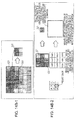
- Japanese Unexamined Patent Application Publication No. 2008-99158 or Japanese Unexamined Patent Application Publication No. 2008-227697 discloses a configuration in which an image with a wide dynamic range is obtained by synthesizing a plurality of images having different exposure amounts. This process will be described with reference to Fig. 1 .
- An imaging device for example, outputs image data of two different exposure times within a video rate (30 to 60 fps) in moving-image photographing. In addition, image data of two different exposure times is generated and output in still-image photographing.
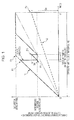
- Fig. 1 is a diagram illustrating the characteristics of images having two different exposure times (long-time exposure image and short-time exposure image) generated by the imaging device.
- a horizontal axis denotes a time t and a vertical axis denotes the charge accumulation amount e in a light sensing photodiode (PD) configuring a photoelectric conversion element corresponding to one pixel of a solid-state imaging element.
- PD light sensing photodiode
- the charge accumulation amount is rapidly increased with the elapse of time.
- the charge accumulation amount is slowly increased with the elapse of time.
- the charge accumulation amount reaches the saturation level (saturation point Px) before reaching the time t3. Accordingly, in the high luminance region 11, only a pixel value corresponding to an electric signal of the saturation level is obtained from the long-time exposure image and, as a result, whitening-out occurs in the pixel.
- the charges accumulated in the light sensing photodiode (PD) are swept out.
- the charges are swept out not to all charges accumulated in the light sensing photodiode (PD) but to an intermediate voltage retention level controlled in the photodiode PD.
- short-time exposure is executed again during an exposure time TS (t2 to t3). That is, the short-time exposure is performed from the short-time exposure start time P2 to the short-time exposure end time P3 shown in the drawing.
- the charge accumulation amount Sb is obtained, and the grayscale level of the pixel is determined based on the electric signal obtained based on the charge accumulation amount Sb.
- the pixel value is determined based on the electric signal based on the charge accumulation amount Sa obtained by the long-time exposure in the low luminance region 12 and the electric signal based on the charge accumulation amount Sb obtained by the short-time exposure in the high luminance region 11, an estimated charge accumulation amount when the same-time exposure is performed or an electric signal output value corresponding to the estimated charge accumulation amount is calculated and a pixel value level is determined based on the calculated result.
- the plurality of images having different exposure amounts becomes images photographed at different timings. Accordingly, when the subject is moved during photographing, a deviation in images occurs when the images are synthesized. As a result, a pseudo color is generated in an image portion of a moving subject region and thus image quality deteriorates. In addition, even when the subject is not moved, the same image quality deterioration may occur if the luminance of the subject is changed.
- Japanese Unexamined Patent Application Publication No. 2008-227697 discloses a pixel value correction method for solving such a problem.
- the pixel value becomes an erroneous value in each position of a pixel position in which the luminance of the subject is changed from high luminance to low luminance and a pixel position in which the luminance of the subject is changed from low luminance to high luminance and thus grayscale failure of the pixel occurs or a pseudo color is generated in the image.
- the blurring process has a purpose of applying, for example, a general low-pass filter (LPF) and blurring the image in regard to the applied filter size (the number of taps), two-dimensional expansion of the imaged pixel as a luminance variation is considered.
- LPF general low-pass filter
- the number of taps of the filter is set to be large.
- information amount is reduced by an image reduction process and the reduced image is enlarged again so as to obtain the same effect as the blurring process.
- a pseudo color having high chroma is output with respect to the moving subject in a large area and the color may be conspicuous even in the blurred image.
- chroma reduction process is performed with respect to the image to which the LPF is applied.
- the correction of the large pseudo color is not sufficient.
- chroma reduction may be conspicuous.
- an image processing device including an image correction unit which receives a synthesized image generated by synthesizing a plurality of images and pseudo color pixel information indicating a pseudo color pixel position included in the synthesized image and executes pixel value correction using a pseudo color pixel in the synthesized image as a pixel to be corrected, wherein the image correction unit selects non-pseudo color pixels, which are not determined as a pseudo color based on the pseudo color pixel information, as reference pixels, from a reference region set in a peripheral region of the pixel to be corrected, sets a similarity weight coefficient in which a large weight is set as a pixel value of the reference pixel is close to a pixel value of the pixel to be corrected and a pixel position weight coefficient in which a large weight is set as the pixel value of the reference pixel is near a pixel position of the pixel to be corrected, with respect to the reference pixels, and determines a correction pixel value of the
- the image correction unit may calculate the similarity weight coefficient according to a difference in pixel value configuration information of the pixels of the synthesized image.
- pixel value information corresponding to a Lab color space may be set in each of the pixels of the synthesized image, and the image correction unit may calculate the similarity weight coefficient according to the difference in each of luminance L and a color difference ab, both of which are pixel value configuration information of the pixels of the synthesized image.
- the image processing device of the embodiment of the present invention may further include a reduced image generation unit which executes a process of reducing the synthetic image, and the image correction unit may set the reference region in the reduced image generated by the reduced image generation unit, and apply a reference pixel selected from the reference region set in the reduced image so as to calculate the similarity weight coefficient and the pixel position weight coefficient.
- a reduced image generation unit which executes a process of reducing the synthetic image
- the image correction unit may set the reference region in the reduced image generated by the reduced image generation unit, and apply a reference pixel selected from the reference region set in the reduced image so as to calculate the similarity weight coefficient and the pixel position weight coefficient.
- a second synthesized image based on an image photographed at a timing different from a first synthesized image including the pixel to be corrected or a reduced image of the second synthesized image may be received as a second reference image
- a second reference region may be set with respect to the second reference image in the vicinity of the pixel position corresponding to the pixel to be corrected of the first synthesized image
- non-pseudo color pixels included in the second reference region are selected as reference pixels
- the similarity weight coefficient and the pixel position weight coefficient may be set with respect to the selected reference pixels
- both the reference pixels selected from the synthesized image including the pixel to be corrected and the reference pixels selected from the second reference region may be applied so as to determine the correction pixel value of the pixel to be corrected by a weighted summation process of summing values obtained by multiplying the pixel values of the reference pixels by the similarity weight coefficient and the pixel position weight coefficient.
- the image correction unit may calculate the similarity weight coefficient and the pixel position weight coefficient by applying a Gaussian function.
- the image processing device of the embodiment of the present invention may further include an image analysis unit which receives the synthesized image and executes detection of the pseudo color pixel included in the synthesized image so as to generate the pseudo color pixel information, and the image correction unit may apply the pseudo color pixel information generated by the image analysis unit so as to perform the selection of the non-pseudo color pixels in the reference region.
- an image analysis unit which receives the synthesized image and executes detection of the pseudo color pixel included in the synthesized image so as to generate the pseudo color pixel information
- the image correction unit may apply the pseudo color pixel information generated by the image analysis unit so as to perform the selection of the non-pseudo color pixels in the reference region.
- the image processing device of the embodiment of the present invention may further include a synthesized image generation unit which synthesizes the plurality of images so as to generate the synthesized image, and the image correction unit may execute the correction of the synthesized image generated by the synthesized image generation unit.
- the synthesized image may be generated by synthesizing the plurality of images photographed by setting different exposure times.
- an imaging apparatus including an imaging device which photographs captured images of different exposure times and the image processing unit which executes the image processing.
- an image processing method which executes pixel value correction in an image processing device, the image processing method including the steps of: at an image correction unit, receiving a synthesized image generated by synthesizing a plurality of images and pseudo color pixel information indicating a pseudo color pixel position included in the synthesized image and executing the pixel value correction using a pseudo color pixel in the synthesized image as a pixel to be corrected, wherein the step of correcting the image includes selecting non-pseudo color pixels, which are not determined as a pseudo color based on the pseudo color pixel information, as reference pixels, from a reference region set in a surrounding region of the pixel to be corrected, setting a similarity weight coefficient in which a large weight is set as a pixel value of the reference pixel is close to a pixel value of the pixel to be corrected and a pixel position weight coefficient in which a large weight is set as the pixel value of the reference pixel is near a pixel position of the image
- a computer program which executes pixel value correction in an image processing device, the program including the steps of: at an image correction unit, receiving a synthesized image generated by synthesizing a plurality of images and pseudo color pixel information indicating a pseudo color pixel position included in the synthesized image and executing the pixel value correction using a pseudo color pixel in the synthesized image as a pixel to be corrected, wherein the step of correcting the image includes selecting non-pseudo color pixels, which are not determined as a pseudo color based on the pseudo color pixel information, as reference pixels, from a reference region set in a surrounding region of the pixel to be corrected, setting a similarity weight coefficient in which a large weight is set as a pixel value of the reference pixel is close to a pixel value of the pixel to be corrected and a pixel position weight coefficient in which a large weight is set as the pixel value of the reference pixel is near a pixel position of the pixel
- a computer program product in which is stored the computer program referred to above, and a computer system loaded with the computer program referred to above.
- the program according to the embodiment of the present invention is, for example, a computer program which may be provided to an information processing device or a computer system for executing various program codes, by a storage medium or a communication medium provided in a computer-readable format.
- a process according to the program is realized on the information processing device or the computer system.
- system is a logical set of a plurality of devices and is not limited to that system in which the devices having the respective configurations are included in the same apparatus.
- a device and method for performing the process of correcting the pseudo color in the synthesized image generated by synthesizing the plurality of images is realized.
- the reference region is set in the vicinity of the pseudo color pixel included in the synthesized image obtained by selectively combining the pixel values of the plurality of images and the non-pseudo color pixels are selected from the reference region as the reference pixels.
- the similarity weight coefficient in which a large weight is set as the pixel value of the reference pixel is close to the pixel value of the pseudo color pixel which is the pixel to be corrected and the pixel position weight coefficient in which a large weight is set as the pixel value of the reference pixel is near the pixel position of the pixel to be corrected are set, and the pixel value of the pixel to be corrected is determined by the weighted summation process of summing the values obtained by multiplying the pixel values of the reference pixels by the similarity weight coefficient and the pixel position weight coefficient.
- Fig. 2 is a block diagram illustrating a configuration example of an imaging apparatus which is an example of an image processing device according to an embodiment of the present invention.
- Light incident through an optical lens 101 enters into an imaging device 102 including, for example, a CMOS image sensor or the like so as to output image data by photoelectric conversion.
- the output image data is input to an image processing unit 104 through a memory 103.
- a controller 105 for example, outputs a control signal to each unit according to a computer program stored in a memory (not shown) so as to control various processes.
- the imaging device 102 generates a plurality of images 111 to 113. For example, images having an overlapping region or the plurality of images 111 to 113 having different exposure times are generated.
- the image processing unit 104 receives the plurality of images 111 to 113, performs a synthesis process, and generates an output image 120.
- the image processing unit 104 executes correction of a pseudo color region generated at the time of the synthesis process of the plurality of images and generates the output image 120.
- the image processing unit 104 receives, for example, the following images.
- the image processing unit 104 receives the N images having different exposure times T1 to TN from the imaging device 102 and generates the output image 120 based on the plurality of images having the different exposure times.
- the electric signal output from the imaging device is generated according to an incident light amount of the imaging device. Accordingly, in a certain exposure time (long-time exposure), an electric signal output from a photoelectric conversion element of a pixel corresponding to a brighter subject may reach a saturation level. As a result, in this pixel, an electric signal of the saturation level is output. Thus, this pixel becomes a so-called whitening-out pixel in which a grayscale difference is not recognized.
- plural pieces of image data of long-time exposure to short-time exposure is generated, and the synthesis process of the plurality of images is executed in the image processing unit 104 so as to obtain the output image 120.
- a process of outputting a pixel value calculated based on data for performing short-time exposure is performed.
- the present invention relates to, for example, a configuration for correcting a pseudo color which is prone to be generated in an image synthesis process of synthesizing a plurality of images such as a plurality of images having different exposure times so as to generate one image.
- the plurality of images having the different exposure amounts become images photographed at different timings. Accordingly, for example, if the subject is moved during photographing, a deviation in image is generated at the time of image synthesis. As a result, a pseudo color is generated in an image region of the moving subject region and thus image quality deteriorates.
- the pseudo color is generated by various factors such as a variation in photographing condition, for example, a variation in brightness, as well as the movement of the subject.
- the image processing unit 104 analyzes the image received from the imaging device 102 and executes a correction process of the detected pseudo color pixel.
- a correction process of the detected pseudo color pixel is described.
- the image processing device executes, for example, a process of correcting a pseudo color generated in a synthesized image generated by synthesizing a plurality of images photographed at different timings, such as a plurality of photographed images having different exposure times.
- the basic process of the pixel value correction executed in the image processing device according to the embodiment of the present invention is a process of setting pixel values of neighboring pixels of a pseudo color pixel to be corrected as reference pixels and determining the pixel value of the pseudo color pixel to be corrected using the pixel values of the reference pixels.
- the luminance of the pixel (pseudo color pixel) to be corrected is verified, and the weights of the neighboring pixels having luminance close to the luminance of the pixel to be corrected are set large so as to perform a pixel value determination process of the pixel to be corrected.
- the overall configuration of the image processing devices commonly have the configuration shown in Fig. 2 .
- the following embodiments are different in the detailed configuration and the process of the image processing unit 104. The details thereof will now be sequentially described.
- the image processing device performs a pixel value correction process of focusing attention on the luminance level of the pseudo color pixel to be corrected at the time of correction of the pseudo color pixel, verifying the luminance of each pixel of a predefined reference region of a neighboring region of the pixel to be corrected, setting the weights of the neighboring pixels having the luminance close to the luminance of the pixel to be corrected as pixels having a high degree of importance to be large, and setting the pixel value of the pixel to be corrected based on the pixel value in the vicinity of the reference region.
- the pixel position on an XY coordinate plane is set to (x, y).
- a process example using a Lab color space as an example of a color space will be described.
- the luminance L and a color difference a, b of the pixel located on the pixel position (x, y) are expressed as following.
- the luminance D L as the signal level of the pixel to be corrected is acquired, the luminance of the neighboring pixels of the pixel to be corrected (pseudo color pixel) are verified, and a pixel having the luminance close to the luminance D L of the pixel to be corrected (pseudo color pixel) is searched for from the neighboring pixels.
- the pixel having the close luminance is a pixel having a high degree of importance, the weights of the color difference D a, b of these pixels is set large, and the pixel value of the pixel to be corrected (pseudo color pixel) is determined so as to perform correction.
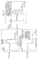
- Figs. 3A to 3C are graphs in which a horizontal axis denotes a pixel position and a vertical axis denotes color difference components D a, b before correction in Fig. 3A , denotes a luminance value D L before correction in Fig. 3B , and denotes color difference components D a, b after correction in Fig. 3C .
- a pixel portion in which a pseudo color is generated are a pixel portion q to r.
- the color difference components D a, b do not have continuity with the neighboring portion p to q or r to s and are broken. is, it is estimated that the pseudo color is generated.
- the pseudo color generation pixel does not have a correct value with respect to the color component (the color difference components D a, b , in the present embodiment), but has a correct value with respect to the luminance component (the luminance value D L , in the present embodiment).
- the horizontal axis denotes the pixel position.
- the pixel range in which the pseudo color is generated is the section q to r.
- the pseudo color is prone to be generated in the synthesis process, for example, when the section p to q is a pixel region selected from an image 1, the section q to r is an image region selected from an image 2 different from the image 1, and the section r to s is an image region selected from an image 3 different from the images 1 and 2.
- the synthesized image is generated by the synthesis of different images. Accordingly, a process of adjusting the luminance levels of the images based on the exposure times of the images is performed. Accordingly, the luminance level is smoothly adjusted over the overall synthesized image.
- color information may be considered at the time of luminance adjustment. Accordingly, as shown in Fig. 3A , the color difference components D a, b are broken.
- the luminance value D L is subjected to an adjustment process between images, it is possible to obtain high-accuracy information. Accordingly, by adjusting the color information, for example, the color difference ab in the Lab color space using this luminance information, the correction process shown in Fig. 3C is performed. That is, it is possible to restore the color (color difference) of the pseudo color region by applying the color (color difference) of the neighboring pixel region having the luminance close to the luminance value of the pseudo color region.
- the value of the luminance D L of the surrounding area is corrected using the color difference D a, b of the neighboring pixel, it is possible to obtain a more natural image and adverse effects such as a sense of incongruity caused as a result of the correction is reduced.
- the configuration example of the image processing unit 104 of the image processing device according to the embodiment of the present invention is shown in Fig. 4 .
- the image processing unit 104 has a synthesized image generation unit 201, an image analysis unit 202 and an image correction unit 203.
- the synthesized image generation unit 201 executes a process of synthesizing the plurality of images so as to generate the synthesized image.
- the image analysis unit 202 generates a pseudo color determination image by the image analysis.
- the image correction unit 203 receives the synthesized image and the pseudo color determination image, executes the process of correcting the pseudo color region of the synthesized image, and generates and outputs the output image 120.
- the image processing unit 104 of the image processing device executes the process of synthesizing the plurality of images so as to generate the synthesized image and correcting the pseudo color region generated in the generated synthesized image.
- the synthesized image generation unit 201 first, for example, receives images having an overlapping region or the plurality of images having different exposure times, for example, the images 111 to 113 shown in Fig. 2 and performs the synthesis process, as described with reference to Figs. 1 and 2 . For example, if the images 111 to 113 are the images having different exposure times, the synthesized image generation unit 201 of the image processing unit 104 receives, for example, the following images.
- the synthesized image generation unit 201 receives the N images having different exposure times T1 to TN from the imaging device 102 shown in Fig. 2 and generates the synthesized image based on the plurality of images having the different exposure times.
- the plurality of images having the different exposure amounts becomes images photographed at different timings. Accordingly, for example, if the subject is moved during photographing, a deviation in image is generated at the time of image synthesis. As a result, a pseudo color is generated in an image region of the moving subject region and thus image quality deteriorates. In addition, the pseudo color is generated by various factors such as a variation in photographing condition, for example, a variation in brightness, as well as the movement of the subject.
- the image analysis unit 202 of the image processing unit 104 shown in Fig. 4 generates the pseudo color determination image for determining the pseudo color pixel region by the image analysis of the synthesized image.
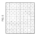
- the pseudo color determination image is, for example, an image in which an identification value (for example, a flag) indicating whether or not it is estimated that each of the pixels configuring the synthesized image is a pseudo color pixel is set.
- the pseudo color determination image is the image in which the identification information of the pixel is set such that the identification flag is set to 0 with respect to the pixel which is estimated to be the pseudo color and the identification flag is set to 1 with respect to the pixel which is not estimated to be the pseudo color.
- the image analysis unit 202 performs the process of executing the image analysis of the synthesized image and detecting the pseudo color pixel.
- the process of detecting the pseudo color region various existing processes are applicable.
- a process of determining that a movement region detected by a movement region detection process in a synthesized image is a pseudo color pixel region which is disclosed in Japanese Patent Application Publication No. 2009-288018 filed by the present applicant, is applicable as a valid method.
- the image correction unit 203 of the image processing unit 104 shown in Fig. 4 receives the synthesized image generated by the synthesized image generation unit 201 and the pseudo color determination image generated by the image analysis unit 202, executes the process of correcting the pseudo color region of the synthesized image, and generates and outputs the output image 120.
- the image correction unit 203 first sets a reference region in the vicinity of the pseudo color pixel to be corrected.
- the reference region is, for example, an nxn pixel region centered on the pseudo color pixel to be corrected.
- n may be variously set to, for example, 3 to 10.
- the image correction unit 203 detects non-pseudo color pixels and pixels having luminance values close to the luminance of the pseudo color pixel to be corrected from the reference region set in the vicinity of the pseudo color pixel.
- the luminance L and a color difference a, b of the pixel located on the pixel position (x, y) are expressed as following.
- the color difference which is the color information of the pixels (pixel position (x, y)) to be corrected of the synthesized image is set to D a, b (x, y) and the color difference of the reference pixel (pixel position (x+i, y+j)) of the reference region in the vicinity of the pixel to be corrected of the synthesized image is set to N a , b (x, y).
- D a, b (x, y) N a, b (x, y).
- the image correction unit 203 calculates the color difference R ab (x, y) which is color information after correction of the pixel (x, y) configuring the synthesized image according to Equation 1.
- the set value of the input image is set to the luminance of the output image, without correction.
- E(i, j) is a pseudo color determination image (see Fig. 5 ) in which 0 is output if the pixel (i, j) is a pseudo color and 1 is output if the pseudo color is not present.
- c(x, y, i, j) (data in which (-) is set on the upper portion of E outputs 1 if it is an inverse value of E(i, j), that is, a pseudo color, and outputs 0 if the pseudo color is not present) is ⁇ Lab indicating a pixel value difference (distance) between the luminance D L (x, y) and the color difference D a, b (x, y), both of which are the pixel value configuration information of the pixel (x, y) in the Lab color space and the luminance D L (x+i, y+j) and the color difference D a, b (x+i, y+j), both of which are the pixel value configuration information of the reference pixel (x+
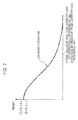
- Fig. 6 is a diagram illustrating a Gaussian function used for setting a weight coefficient of a reference pixel.
- P(x, y, i, j) is a Gaussian function of a spatial space between the pixel (x, y) and the pixel (x+i, y+j). For example, it is the result of converting the spatial space between the pixel (x, y) and the pixel (x+i, y+j) according to the Gauss curved line shown in Fig. 6 .
- ⁇ included in each Gaussian function is a Gaussian parameter and t is the number of taps in the x and y directions.
- the Gaussian parameter is set large, correction is facilitated, but adverse effects are increased.
- the image correction unit 203 calculates the color difference R ab (x, y) which is the color information of the output pixel after correction of the pixel (x, y) to be corrected of the synthesized image according to Equation 1.
- Equation 1 the process of setting the non-pseudo color pixels (the pixels set to 1 in the pseudo color determination image (see Fig. 5 )) and the reference pixels having the pixel value Lab close to color difference D a, b (x, y) and D L (x, y), which is the pixel value configuration information of the pseudo color pixel to be corrected from the reference region set in the vicinity of the pseudo color pixel as important pixels, setting the weights of the important pixels to be large, setting the weights of the pixels near the pseudo color pixel to be corrected to be large, and calculating the correction pixel value of the pseudo color pixel based on the pixel values of the pixels of the reference region is performed.
- Equation 1 the weights according to the pixel values close to the pixel value configuration information Lab of the pseudo color pixel correspond to C(x, y, i, j) and the weights of the pixels according to the distance with the pseudo color pixel correspond to P(x, y, i, j).
- the weight coefficient according to pixel value similarity is C(x, y, i, j) and the weight coefficient according to the distance between pixels (pixel position weight coefficient) is P(x, y, i, j). These weights become the weights according to the Gauss curved line shown in Fig. 7 .
- the image correction unit 203 sets the similarity weight coefficient in which a large weight is set as the pixel value of the reference pixel that is close to the pixel value of the pixel to be corrected and the pixel position weight coefficient in which a large weight is set as the pixel value of the reference pixel that is near the pixel position of the pixel to be corrected.
- the similarity weight coefficient is calculated according to a difference of each pixel value configuration information.
- a large weight is set with respect to a reference pixel having a pixel value (Lab) close to color difference D a, b (x, y) and D L (x, y), which are the pixel value configuration information of the pseudo color pixel to be corrected, a large weight is set with respect to a reference pixel near the pseudo color pixel to be corrected, the set weight is applied, and the color information (color difference N ab (x+i, y+j) of the plurality of pixels in the reference region is subjected to a weighted summation so as to determine the color value (color difference D ab (x, y) of the pixel (pseudo color pixel) to be corrected.
- the set value of the input image is set to the luminance of the output image, without correction.
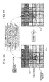
- Fig. 8A shows an image before correction of the pseudo color pixel 221 to be corrected and Fig. 8B shows an image after correction of the pseudo color pixel 221 to be corrected.
- a 3x3 pixel region including the neighboring pixels of the pseudo color pixel 221a to be corrected is a reference region.
- the non-pseudo color pixel (the pixel which is set to 1 in the pseudo color determination image (see Fig. 5 )) is selected from the reference region shown in Fig. 8A .
- Fig. 8A only the pseudo color pixel is set to 0.
- the pixels which are not set to 0 are non-pseudo color pixels.
- the pseudo color pixel among the eight pixels of the reference region other than the pseudo color pixel 221a to be corrected is only a pixel 223.
- the pixel values of the seven pixels excluding the pseudo color pixel 223 become the reference pixels used to determine the pixel value (color difference D ab (x, y)) of the pseudo color pixel 221.
- the luminance N L (x+i, y+j) of the seven reference pixels and the color difference N ab (x+i, y+j) of the seven reference pixels are used in Equation 1.
- i and j denote deviations between the coordinate positions of the pseudo color pixel 221a to be corrected and the reference pixel and N denotes a pixel number.
- N denotes a pixel number.
- the pixel value (color difference D ab (x, y)) of the pseudo color pixel 221 is determined according to Equation 1.
- a correction result image in which the color difference of the pseudo color pixel 221 is corrected is generated.
- the color difference R ab (x, y) calculated according to Equation 1 is set.
- the luminance D L (x, y) is equal to that at the time of input and is not changed.
- the image correction unit 203 first selects the non-pseudo color pixels which are not determined as the pseudo color based on the pseudo color pixel information generated by the image analysis unit 202 as the reference pixels, from the reference region set in the vicinity of the pixel to be corrected.
- the similarity weight coefficient in which a large weight is set as the pixel value of the reference pixel is close to the pixel value of the pixel to be corrected and the pixel position weight coefficient in which a large weight is set as the pixel value of the reference pixel is near the pixel position of the pixel to be corrected are set with respect to each reference pixel.
- the correction pixel value of the pixel to be corrected is determined by the weighted summation process of multiplying and summing the similarity weight coefficient and the pixel position weight coefficient.
- Embodiment 2 is an example of a process of generating a reduced image of a synthesized image and applying the reduced image so as to calculate a correction pixel value of a pseudo color pixel.
- An image 301 shown in Fig. 9A is a synthesized image 301 including a pseudo color pixel to be corrected.
- a correction pixel value is calculated with respect to a pseudo color pixel 311 included in the synthetic image 301, for example, a process of setting a reference region a312 shown in Fig. 9A and acquiring a pseudo color determination result of a pixel included in the reference region a312 and a pixel value Lab is performed and a pixel value calculation process to which Equation 1 described in Embodiment 1 is applied is performed.
- the processing amount and the calculation amount are increased according to the increase in the number of pixels included in the reference region a312.
- a reduced image 302 obtained by reducing the synthesized image 301 is generated and a reference region b322 is set in the vicinity of a pseudo color pixel of the reduced image 302 so as to perform processing, it is possible to reduce the number of pixels included in the reference region b322 as compared with the number of pixels included in the reference region a312 after reduction.
- the image processing device has the configuration shown in Fig. 2 .
- the configuration of the image processing unit 104 is different from that of Embodiment 1.
- the configuration example of the image processing unit 104 according to Embodiment 2 is shown in Fig. 10 .
- the image processing unit 104 includes a reduced image generation unit 331, in addition to a synthesized image generation unit 201, an image analysis unit 202 and an image correction unit 203, all of which perform the same processing as Embodiment 1.
- the synthesized image generation unit 201, the image analysis unit 202 and the image correction unit 203 basically have the same configuration as Embodiment 1 and execute the same processing.
- the image correction unit 203 executes a process of using the reduced image as well as the synthesized image.
- the synthesized image generation unit 201 executes a process of synthesizing a plurality of images so as to generate the synthesized image.
- the reduced image generation unit 331 executes a process of reducing the synthesized image generated by the synthesized image generation unit 201 so as to generate the reduced image.
- the image analysis unit 202 generates a pseudo color determination image by the image analysis of the synthesized image.
- the pseudo color determination image is an image for distinguishing a pseudo color pixel and a non-pseudo color pixel described with reference to Fig. 5 .
- the image correction unit 203 receives the synthesized image, the reduced image and the pseudo color determination image, executes the process of correcting the pseudo color region of the synthesized image so as to generate the corrected synthesized image, and generates and outputs the output image 120.
- the image correction unit 203 receives the reduced synthesized image based on the synthesized image and the pseudo color determination image corresponding to the synthesized image generated by the image analysis unit 202 and executes the process of correcting the pseudo color region of the synthesized image.
- the basic processing mode of the process of correcting the pseudo color pixel, which is executed by the image correction unit 203, is equal to that of Embodiment 1. That is, a reference region is set in the vicinity of the pseudo color pixel to be corrected, and non-pseudo color pixels and pixels having luminance values close to the luminance of the pseudo color pixel to be corrected are detected from the set reference region.
- the image correction unit 203 performs the process by acquiring a weight coefficient (similarity weight coefficient) C(x, y, i, j) according to similarity of the pixel value, a weight coefficient (pixel position weight coefficient) P(x, y, i, j) according to a distance between pixels, and a color difference N ab (x+i, y+j) of the reference pixels in Equation 1 from the reduced image.
- the pixel position of the synthesized image before reduction is set to (x, y) and the pixel position of the reduced synthesized image after reduction is set to (X, Y).
- the pixel position (X, Y) of the reduced synthesized image is defined by the following relationship equation using the pixel position (x, y) of the synthesized image before reduction.
- X ⁇ Y x / Q , y / Q
- the image correction unit 203 performs the process of setting the weights of the reference pixels having the pixel values Lab close to D L (X, Y) and the color difference D a, b (x, y), both of which are the pixel value configuration information of the pseudo color pixel to be corrected to be large, setting the weights of the reference pixels near the pseudo color pixel to be large, and calculating the correction pixel value of the pseudo color pixel based on the pixel values of the pixels of the reference region.
- the luminance L and the color difference a, b of the pixel located on the pixel position (x, y) of the synthesized image are expressed as following.
- the image correction unit 203 calculates the color difference R ab (x, y) which is color information after correction of the pixel (x, y) configuring the synthesized image according to Equation 2.
- the set value of the input image is set to the luminance of the output image, without correction.
- E(i, j) is a pseudo color determination image (see Fig. 5 ) in which 0 is output if the pixel (i, j) is a pseudo color and 1 is output if the pseudo value is not present.
- c(X, Y, i, j) is ⁇ Lab indicating a pixel value difference (distance) between the luminance D L (x, y) and the color difference D a, b (x, y), both of which are the pixel value configuration information of the pixel (x, y) in the Lab color space and the luminance D L (X+i, Y+j) and the color difference D a, b (X+i, Y+j), both of which are the pixel value configuration information of the reduced reference pixel (
- C(X, Y, i, j) is a Gaussian function (see Figs. 6 and 7 ) of c(X, Y, i, j).
- P(X, Y, i, j) is a Gaussian function (see Figs. 6 and 7 ) of a spatial space between the pixel (X, Y) located on the corresponding position of the pseudo color pixel (x, y) set with respect to the reduced image and the pixel (X+i, Y+j).
- the image correction unit 203 calculates the color difference R ab (x, y) which is the color information of the output pixel after correction of the pixel (x, y) to be corrected of the synthesized image according to Equation 2.
- Equation 2 similarly to Equation 1 applied to Embodiment 1, the process of setting the non-pseudo color pixels (the pixels set to 1 in the pseudo color determination image (see Fig. 5 )) and the reference pixels having the pixel value Lab close to D L (x, y) and the color difference D a, b (x, y), both of which are the pixel value configuration information of the pseudo color pixel to be corrected from the reference region set in the vicinity of the pseudo color pixel as important pixels, setting the weights of the important pixels to be large, setting the weights of the pixels near the pseudo color pixel to be corrected to be large, and calculating the correction pixel value of the pseudo color pixel based on the pixel values of the pixels of the reference region is performed.
- the image correction unit 203 performs the process by acquiring the following parameters included in Equation 2, that is, a weight coefficient (similarity weight coefficient) C(X, Y, i, j) according to similarity of the pixel value, a weight coefficient (pixel position weight coefficient) P(X, Y, i, j) according to a distance between pixels, and the color difference N ab (X+i, Y+j) of the reference pixels from the reduced image.
- the number of synthesized images including the pseudo color pixel to be corrected or the number of reduced images thereof, which is used as an image for acquiring the reference pixels was one. That is, the number of reference images was one.
- Embodiment 3 is an example of a process in which at least two reference images are applied.
- a plurality of synthesized images such as a first synthesized image including a pseudo color pixel to be corrected and a second synthesized image based on an image photographed at timing different from that of the first synthesized image is set as reference images and a correction pixel value of the pseudo color pixel is calculated using reference pixel values acquired from a reference region set in the plurality of reference images.
- a correction value of a pseudo color of an image to be corrected is calculated using the plurality of reference images.
- the first reference image the first synthesized image including the pseudo color image which is the pixel to be corrected
- the second reference image the reduced image of the second synthesized image generated based on the preceding photographed image before the first synthesized image
- the image processing device has the configuration shown in Fig. 2 .
- the configuration of the image processing unit 104 is different from that of Embodiments 1 and 2.
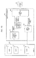
- the configuration example of the image processing unit 104 according to Embodiment 3 is shown in Fig. 12 .
- the image processing unit 104 includes a frame memory 401 for temporarily storing a reduced image in addition to a synthesized image generation unit 201, an image analysis unit 202 and an image correction unit 203, all of which perform the same processing as Embodiment 1, and a reduced image generation unit 331 for generating a reduced image similarly to Embodiment 2.
- the image correction unit 203 receives the synthesized image to be corrected.
- This synthesized image is an image to be corrected and is also the first reference image.
- the image correction unit 203 receives the reduced image generated based on the preceding synthesized image generated by the photographing process of the previous timing of the synthesized image to be corrected from the frame memory 401. This reduced image is used as the second reference image.
- the synthesized image generation unit 201, the image analysis unit 202 and the image correction unit 203 basically have the same configuration as Embodiment 1 and execute the same process.
- the image analysis unit 202 generates a pseudo color determination image by the image analysis of the synthesized image.
- the pseudo color determination image is an image for distinguishing a pseudo color pixel and a non-pseudo color pixel described with reference to Fig. 5 .
- the image correction unit 203 receives the synthesized image, the reduced image and the pseudo color determination image, executes the process of correcting the pseudo color region of the synthesized image so as to generate the corrected synthesized image, and generates and outputs the output image 120.
- the basic processing mode of the process of correcting the pseudo color pixel which is executed by the image correction unit 203, is equal to that of Embodiments 1 and 2. That is, a reference region is set in the vicinity of the pseudo color pixel to be corrected, and non-pseudo color pixels and pixels having luminance values close to the luminance of the pseudo color pixel to be corrected are detected from the set reference region.
- p is the same equation of the term of the first half of the calculation equation of the output pixel value Ra, b(x, y) after correction of Equation 1 of Embodiment 1.
- q is the same equation of the term of the first half of the calculation equation of the output pixel value Ra, b(x, y) after correction of Equation 2 of Embodiment 2.
- p is calculated from the reference pixel selected from the same synthesized image (the first reference image) as the image to be corrected
- q is calculated from the reference pixel selected from the reduced image (the second reference image) of the synthesized image different from the image to be corrected.
- the other parameters are the same parameters described in Embodiments 1 and 2.
- E(i, j) is a pseudo color determination image (see Fig. 5 ) in which 0 is output if the pixel (i, j) is a pseudo color and 1 is output if the pseudo value is not present.
- c(x, y, i, j) is ⁇ Lab indicating a pixel value difference (distance) between the luminance D L (x, y) and the color difference D a , b (x, y), both of which are the pixel value configuration information of the pixel (x, y) in the Lab color space and the luminance D L (x+i, y+j) and the color difference D a , b (x+i, y+j), both of which are the pixel value configuration information of the first reference pixel (x+i, y+j).
- C(x, y, i, j) is a Gaussian function (see Figs. 6 and 7 ) of c(x, y, i, j).
- P(x, y, i, j) is a Gaussian function (see Figs. 6 and 7 ) of a spatial space between the pixel (x, y) and the pixel (x+i, y+j) of the first reference image.
- c(X, Y, i, j) is ⁇ Lab indicating a pixel value difference (distance) between the luminance D L (x, y) and the color difference D a , b (x, y), both of which are the pixel value configuration information of the pixel (x, y) in the Lab color space and the luminance D L (X+i, Y+j) and the color difference D a , b (X+i, Y+j), both of which are the pixel value configuration information of the reduced pixel (X+i, Y+j) of the second reference image.
- C(X, Y, i, j) is a Gaussian function (see Figs. 6 and 7 ) of c(X, Y, i, j).
- P(X, Y, i, j) is a Gaussian function (see Figs. 6 and 7 ) of a spatial space between the pixel (X, Y) located on the corresponding position of the pseudo color pixel (x, y) set with respect to the second reference image (reduced image) and the pixel (X+i, Y+j).
- the image correction unit 203 calculates the color difference R ab (x, y) which is the color information of the output pixel after correction of the pixel (x, y) to be corrected of the synthesized image according to Equation 3.
- Equation 3 similarly to Equation 1 applied to Embodiments 1 and 2, the process of setting the non-pseudo color pixels (the pixels set to 1 in the pseudo color determination image (see Fig. 5 )) and the reference pixels having the pixel value Lab close to D L (x, y) and the color difference D a , b (x, y), both of which are the pixel value configuration information of the pseudo color pixel to be corrected from the reference region set in the vicinity of the pseudo color pixel as important pixels, setting the weights of the important pixels to be large, setting the weights of the pixels near the pseudo color pixel to be corrected to be large, and calculating the correction pixel value of the pseudo color pixel based on the pixel values of the pixels of the reference region is performed.
- the image correction unit 203 calculates the correction pixel value by applying the plurality of different reference images. By increasing the reference image, it is possible to increase accuracy of the correction value.
- the preceding image is referred as the reduced images
- a configuration for setting the first synthesized image including the pixel to be corrected to the first reference image without performing the reduction process, setting the second synthesized image which does not include the pixel to be corrected to the second reference image without reduction, and acquiring the reference pixels from the images so as to calculate the correction pixel value may be used.
- a configuration for performing a process of setting three or more different images as the reference images may be used.
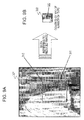
- Fig. 13 shows an example of a process of generating a general reduced image
- Fig. 14 shows an example of a process of generating a reduced image in consideration of the presence of a pseudo color according to one embodiment of the present invention.
- Fig. 13A1 an example of a process of reducing 6 ⁇ 6 pixels to 2x2 pixels is shown. That is, it is an example of a process of reducing 3x3 pixels of an original image to one pixel of a reduced image.
- a block 501 of 3x3 pixels of a right upper side of an original image of 6x6 pixels is set as a pixel 502 of a reduced image.
- a process of setting a pixel value in the reduction process of the related art will be described with reference to Fig. 13A2 .
- An example of setting a pixel value of a pixel 502 of a right upper side of the reduced image of 2x2 pixels will be described.
- the pixel value of the pixel 502 of the right upper side of the reduced image is set as an average value of the pixel values of 9 pixels configuring the block 501 of 3x3 pixels of the right upper side of the original image of 6x6 pixels.
- Equation 5 The calculation equation of the pixel value of the general reduced image is expressed by Equation 5.
- the reduction process generates the reduced image having a size of 1/n of that of the original image.
- the pixel value of the pixel of the pixel position (i, j) of the reduced image is set to P L , a , b (i, j).
- the pixel value P L , a , b (i, j) of the pixel of the pixel position (i, j) of the reduced image is calculated by Equation 4.
- i, j are coordinates indicating the pixel position of the reduced image and respectively denote the pixel positions in the x and y directions.
- Fig. 13A2 In the example shown in Fig.
- the pixel value P L, a, b (i, j) of the pixel 502 of the reduced image is calculated by the following equation.
- the pixel value P L, a, b (i, j) of the reduced image is calculated.
- the influence of the pseudo color is left in the pixel value set in the reduced image.
- a reduced image in which the influence of the pseudo color is reduced is generated in consideration of the presence of the pseudo color in each pixel.
- FIG. 14 an example of a process of reducing 6x6 pixels to 2x2 pixels is shown. That is, it is an example of a process of reducing 3x3 pixels of an original image to one pixel of a reduced image.
- a block 521 of 3x3 pixels of a right upper side of an original image of 6x6 pixels is set as a pixel 523 of a reduced image.
- one pseudo color pixel 522 is included.
- each of 9 pixels configuring the block 521 of the 3x3 pixels of the right upper side of the original image of the 6x6 pixels is a pseudo color pixel or a non-pseudo color pixel.
- the determination information for example, the pseudo color determination image generated by the image analysis unit 202 in the image processing unit 104 described in Embodiments 1 to 3 may be used.
- the weight of each pixel in the block is set, that is, is set to different values depending on whether it is a pseudo color.
- the weight is set to be small if it is a pseudo color pixel and is set to be large if it is a non-pseudo color pixel.
- the weight is set as follows.
- the pixel value of the reduced image is determined by summing values obtained by multiplying the pixel values P(x, y) of the pixels included in the block of the 3x3 pixels of the right upper side of the original image of the 6x6 pixels by the weight k(x, y). That is, the pixel value of the configuration pixel of the reduced image is set by weighted summation in which the weight is set in consideration of the pseudo color of each pixel in the block of the original image.
- Equation 5 The calculation equation of the pixel value of the reduced image according to the embodiment of the present invention is expressed by Equation 5.
- the reduction process generates the reduced image having a size of 1/n of that of the original image.
- the pixel value of the pixel of the pixel position (i, j) of the reduced image is set to P L, a, b (i, j).
- the pixel value P L, a, b (i, j) of the pixel of the pixel position (i, j) of the reduced image is calculated by Equation 5.
- i, j are coordinates indicating the pixel position of the reduced image and respectively denotes the pixel positions in the x and y directions.
- E(k, 1) is a pseudo color determination image (see Fig. 5 ) in which 0 is output if the pixel (k, l) of the configuration pixel of the original image before reduction and 1 is output if the pseudo color is not present.
- the pixel value P L, a, b (i, j) of the pixel 523 of the reduced image is calculated by the following equation.
- the pixel value P L, a, b (i, j) of the reduced image is calculated.
- the weight of the pseudo color pixel is lower than that of the non-pseudo color pixel (for example, 1/10), it is possible to reduce the influence of the pseudo color pixel on the pixel values of the configuration pixels of the reduced image and to generate the high-quality reduced image in which the influence of the pseudo color is reduced.
- the correction is more appropriately performed.
- the process of generating the reduced image which is described with reference to Fig. 14 , is, for example, applicable to the process of generating the reduced image in the reduced image generation unit 331 of Embodiments 2 and 3.
- a configuration in which the reduced image generation unit 331 in Embodiments 2 and 3 performs a process of performing a low-pass filter with respect to a color difference component of the reduced image after generating the reduced image may be used.
- the low-pass filter By applying the low-pass filter to the reduced image so as to convert the pixel values of the reduced image, if a high frequency component is reduced and an extreme value largely different from the surrounding area is present in the pixel values of the reference pixels acquired from the reduced image, it is possible to reduce the influence thereof, to reduce the influence generated by employing erroneous pixel values as the reference pixel values, and to perform the correction process with high accuracy.
- even when the process of performing reduction without considering the pseudo color see Fig. 13 ), it is possible to enable the pseudo color portion to be blurred so as to be inconspicuous by performing the low-pass filter.
- the present invention is not limited to the Lab color space and may be used in the case where the other color space is applied.
- each of the configuration pixels of the synthesized image has the pixel value corresponding to the Lab color space. That is, each pixel has luminance information L and the color difference ab which is the color information, as the configuration information of the pixel value.
- L luminance information
- ab color difference
- Cb and Cr values of YCbCr may be used, instead of the color difference ab which is the color information corresponding to the Lab color space.
- a Y value of YCbCr may be used instead of L which is the luminance information corresponding to the Lab color space.
- ⁇ YCbCr may be used instead of ⁇ Lab.
- Embodiments 1 to 3 for example, if the weight coefficients: the weight coefficient according to pixel value similarity (similarity weight coefficient) C(x, y, i, j) and the weight coefficient according to the distance between pixels (pixel position weight coefficient) P(x, y, i, j) are set, the weights are set by applying the Gaussian function as described with reference to Figs. 6 and 7 .
- Equation 6 the norm shown in Equation 6 is used as the input to the Gaussian function.
- Equation 7 a difference absolute value distance shown in Equation 7 may be applied.
- the Gaussian function is applied as described with reference to Figs. 6 and 7 .
- a configuration for performing an approximation process using a function indicating an approximated broken line shown in Fig. 15 or a fixed value and calculating the weight coefficients may be used. It is possible to reduce the computation amount by performing approximation by a simple function.
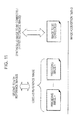
- the pixel information other than the color difference ab such as the luminance information L may be changed.
- a determination as to whether or not this process is performed is preferably made according to the property of the image to be corrected.
- Embodiments 1 to 3 aids the case 3, that is, the case "the luminance is correct but the color difference is erroneous.
- the correction process is unnecessary and, in the case 3, the processes of Embodiments 1 to 3 are preferable.
- the process of correcting the luminance is preferably executed.
- the image subjected to the pseudo color correction is output as a final processed image
- a configuration for performing a blurring process using the low-pass filter with respect to the corrected image subjected to the pseudo color correction may be used.
- the application position of the low-pass filter is set to only the pixel portion in which the pseudo color correction is executed.
- the low-pass filter may be used for only the color difference component.
- a series of processes described in the specification may be executed by hardware, software or a combination thereof. If the processes are executed by software, a computer program having a processing procedure recorded therein may be installed in a memory of a computer in which dedicated hardware is assembled or may be installed in a general-purpose computer for executing various processes so as to be executed. For example, the program may be recorded on a recording medium in advance. In addition to the installation from the recording medium to the computer, the program may be received through a network such as Local Area Network (LAN) or the Internet and may be installed on the recording medium such as a built-in hard disk.
- LAN Local Area Network
- the Internet may be installed on the recording medium such as a built-in hard disk.
- the various processes described in the specification may be executed in parallel or individually as necessary or according to the processing capability of the device for executing the processes, in addition to the time-series execution.
- the system is a logical set of a plurality of devices and is not limited to a system in which the devices having the respective configurations are included in the same apparatus.
Landscapes
- Engineering & Computer Science (AREA)
- Multimedia (AREA)
- Signal Processing (AREA)
- Image Processing (AREA)
- Studio Devices (AREA)
- Color Television Image Signal Generators (AREA)
- Color Image Communication Systems (AREA)
Applications Claiming Priority (2)
| Application Number | Priority Date | Filing Date | Title |
|---|---|---|---|
| JP2009216530 | 2009-09-18 | ||
| JP2010044944A JP5589446B2 (ja) | 2009-09-18 | 2010-03-02 | 画像処理装置、撮像装置、および画像処理方法、並びにプログラム |
Publications (2)
| Publication Number | Publication Date |
|---|---|
| EP2299697A2 true EP2299697A2 (de) | 2011-03-23 |
| EP2299697A3 EP2299697A3 (de) | 2012-09-12 |
Family
ID=43037637
Family Applications (1)
| Application Number | Title | Priority Date | Filing Date |
|---|---|---|---|
| EP10174844A Withdrawn EP2299697A3 (de) | 2009-09-18 | 2010-09-01 | Bildverarbeitungsvorrichtung, Bildgebungsvorrichtung, Abbildungsverarbeitungsverfahren und Programm |
Country Status (5)
| Country | Link |
|---|---|
| US (1) | US8384805B2 (de) |
| EP (1) | EP2299697A3 (de) |
| JP (1) | JP5589446B2 (de) |
| CN (1) | CN102025918B (de) |
| TW (1) | TW201130302A (de) |
Cited By (1)
| Publication number | Priority date | Publication date | Assignee | Title |
|---|---|---|---|---|
| GB2487842A (en) * | 2011-02-07 | 2012-08-08 | Canon Kk | Generation of an Extended Dynamic Range Image |
Families Citing this family (20)
| Publication number | Priority date | Publication date | Assignee | Title |
|---|---|---|---|---|
| JP4905187B2 (ja) * | 2007-03-09 | 2012-03-28 | ソニー株式会社 | 画像処理装置、撮像装置、および画像処理方法、並びにコンピュータ・プログラム |
| JP4914303B2 (ja) * | 2007-07-13 | 2012-04-11 | シリコン ヒフェ ベー.フェー. | 画像処理装置及び撮像装置、画像処理方法及び撮像方法、画像処理プログラム |
| JP5136664B2 (ja) * | 2010-07-09 | 2013-02-06 | カシオ計算機株式会社 | 画像処理装置、及びプログラム |
| US9077910B2 (en) * | 2011-04-06 | 2015-07-07 | Dolby Laboratories Licensing Corporation | Multi-field CCD capture for HDR imaging |
| CN103188520B (zh) * | 2011-12-28 | 2016-08-03 | 阿里巴巴集团控股有限公司 | 一种图像调整方法和装置 |
| JP6024107B2 (ja) | 2012-01-06 | 2016-11-09 | 株式会社リコー | 画像処理装置、撮像装置、画像処理方法およびプログラム |
| JP5978949B2 (ja) * | 2012-03-16 | 2016-08-24 | 富士通株式会社 | 画像合成装置及び画像合成用コンピュータプログラム |
| JP6020036B2 (ja) | 2012-10-24 | 2016-11-02 | 富士ゼロックス株式会社 | 情報処理装置、情報処理システム、およびプログラム |
| CN103973997B (zh) * | 2013-02-05 | 2017-09-26 | 浙江大华技术股份有限公司 | 一种图像处理方法及装置 |
| US9571720B2 (en) * | 2013-12-10 | 2017-02-14 | Olympus Corporation | Image processing device, display device, imaging apparatus, image processing method, and program |
| JP2015204489A (ja) * | 2014-04-11 | 2015-11-16 | ハンファテクウィン株式会社Hanwha Techwin Co.,Ltd. | 画像処理装置および画像処理方法 |
| GB2523253B (en) * | 2015-01-23 | 2017-04-12 | Visidon Oy | Image processing method |
| US9521351B1 (en) | 2015-09-21 | 2016-12-13 | Rambus Inc. | Fractional-readout oversampled image sensor |
| JP6779649B2 (ja) * | 2016-04-12 | 2020-11-04 | キヤノン株式会社 | 画像処理装置、撮像装置、画像処理方法、画像処理プログラムおよび記録媒体 |
| US10129511B2 (en) * | 2016-08-01 | 2018-11-13 | Ricoh Company, Ltd. | Image processing apparatus, image projection apparatus, and image processing method |
| US11328388B2 (en) * | 2017-08-01 | 2022-05-10 | Sony Group Corporation | Image processing apparatus, image processing method, and program |
| TWI694434B (zh) * | 2019-04-02 | 2020-05-21 | 友達光電股份有限公司 | 具有雙面板的顯示裝置的調整方法 |
| KR102741512B1 (ko) | 2020-07-30 | 2024-12-11 | 엘지디스플레이 주식회사 | 표시장치와 이를 포함한 모바일 단말기 |
| CN113870146B (zh) * | 2021-10-15 | 2024-06-25 | 中国大恒(集团)有限公司北京图像视觉技术分公司 | 一种彩色相机图像边缘伪彩的校正方法 |
| CN117528045B (zh) * | 2024-01-04 | 2024-03-22 | 深圳市云影天光科技有限公司 | 一种基于视频透雾增透技术的视频图像处理方法及系统 |
Citations (3)
| Publication number | Priority date | Publication date | Assignee | Title |
|---|---|---|---|---|
| JP2008099158A (ja) | 2006-10-16 | 2008-04-24 | Sony Corp | 固体撮像装置、固体撮像装置の駆動方法および撮像装置 |
| JP2008227697A (ja) | 2007-03-09 | 2008-09-25 | Sony Corp | 画像処理装置、撮像装置、および画像処理方法、並びにコンピュータ・プログラム |
| JP2009288018A (ja) | 2008-05-28 | 2009-12-10 | Panasonic Electric Works Co Ltd | 電波センサ |
Family Cites Families (15)
| Publication number | Priority date | Publication date | Assignee | Title |
|---|---|---|---|---|
| US6204881B1 (en) * | 1993-10-10 | 2001-03-20 | Canon Kabushiki Kaisha | Image data processing apparatus which can combine a plurality of images at different exposures into an image with a wider dynamic range |
| JP3490888B2 (ja) * | 1998-03-10 | 2004-01-26 | 三洋電機株式会社 | 色抑圧回路 |
| JP4282113B2 (ja) * | 1998-07-24 | 2009-06-17 | オリンパス株式会社 | 撮像装置および撮像方法、並びに、撮像プログラムを記録した記録媒体 |
| US20020135683A1 (en) * | 1999-12-20 | 2002-09-26 | Hideo Tamama | Digital still camera system and method |
| JP4235903B2 (ja) * | 2003-09-10 | 2009-03-11 | ソニー株式会社 | 撮像装置 |
| JP4539299B2 (ja) * | 2004-11-08 | 2010-09-08 | ソニー株式会社 | 画像処理装置、および画像処理方法、並びにコンピュータ・プログラム |
| KR100721338B1 (ko) * | 2004-12-30 | 2007-05-28 | 엘지전자 주식회사 | 디지털 촬영장치의 색상 보간법 |
| JP4780374B2 (ja) * | 2005-04-21 | 2011-09-28 | Nkワークス株式会社 | 粒状ノイズ抑制のための画像処理方法及びプログラム及びこの方法を実施する粒状抑制処理モジュール |
| JP4789140B2 (ja) * | 2005-05-19 | 2011-10-12 | 株式会社メガチップス | 画像処理装置 |
| US7667747B2 (en) * | 2006-03-15 | 2010-02-23 | Qualcomm Incorporated | Processing of sensor values in imaging systems |
| JP4977395B2 (ja) * | 2006-04-14 | 2012-07-18 | 富士フイルム株式会社 | 画像処理装置及び方法 |
| JP4410225B2 (ja) * | 2006-08-07 | 2010-02-03 | 株式会社東芝 | 動画像復号化装置および方法 |
| ITVA20060082A1 (it) * | 2006-12-22 | 2008-06-23 | St Microelectronics Srl | "metodo di trattamento di un'immagine digitale per ridurre eventuali effetti di color bleeding" |
| JP2007251997A (ja) * | 2007-05-28 | 2007-09-27 | Olympus Corp | 撮像装置 |
| KR101340518B1 (ko) * | 2007-08-23 | 2013-12-11 | 삼성전기주식회사 | 영상의 색수차 보정 방법 및 장치 |
-
2010
- 2010-03-02 JP JP2010044944A patent/JP5589446B2/ja not_active Expired - Fee Related
- 2010-08-27 TW TW099128956A patent/TW201130302A/zh unknown
- 2010-09-01 EP EP10174844A patent/EP2299697A3/de not_active Withdrawn
- 2010-09-10 CN CN2010102808838A patent/CN102025918B/zh not_active Expired - Fee Related
- 2010-09-10 US US12/879,877 patent/US8384805B2/en active Active
Patent Citations (3)
| Publication number | Priority date | Publication date | Assignee | Title |
|---|---|---|---|---|
| JP2008099158A (ja) | 2006-10-16 | 2008-04-24 | Sony Corp | 固体撮像装置、固体撮像装置の駆動方法および撮像装置 |
| JP2008227697A (ja) | 2007-03-09 | 2008-09-25 | Sony Corp | 画像処理装置、撮像装置、および画像処理方法、並びにコンピュータ・プログラム |
| JP2009288018A (ja) | 2008-05-28 | 2009-12-10 | Panasonic Electric Works Co Ltd | 電波センサ |
Cited By (3)
| Publication number | Priority date | Publication date | Assignee | Title |
|---|---|---|---|---|
| GB2487842A (en) * | 2011-02-07 | 2012-08-08 | Canon Kk | Generation of an Extended Dynamic Range Image |
| GB2487842B (en) * | 2011-02-07 | 2013-04-17 | Canon Kk | Image processing apparatus, control method thereof, program, and recording medium |
| US9426382B2 (en) | 2011-02-07 | 2016-08-23 | Canon Kabushiki Kaisha | Image processing apparatus and method in which first and second images are combined in a weighted manner based on a third image |
Also Published As
| Publication number | Publication date |
|---|---|
| JP5589446B2 (ja) | 2014-09-17 |
| JP2011086275A (ja) | 2011-04-28 |
| TW201130302A (en) | 2011-09-01 |
| EP2299697A3 (de) | 2012-09-12 |
| US20110115942A1 (en) | 2011-05-19 |
| CN102025918A (zh) | 2011-04-20 |
| US8384805B2 (en) | 2013-02-26 |
| CN102025918B (zh) | 2013-07-31 |
Similar Documents
| Publication | Publication Date | Title |
|---|---|---|
| EP2299697A2 (de) | Bildverarbeitungsvorrichtung, Bildgebungsvorrichtung, Abbildungsverarbeitungsverfahren und Programm | |
| US9560290B2 (en) | Image processing including image correction | |
| US8798395B2 (en) | Image processing apparatus, image processing method, and program | |
| TWI432019B (zh) | An image processing apparatus, an image pickup apparatus, an image processing method, and an image processing program | |
| US9571742B2 (en) | Image capture apparatus and control method thereof | |
| US8587692B2 (en) | Method and apparatus for increasing dynamic range of image by using electronic shutter | |
| US8605999B2 (en) | Signal processing apparatus and method, noise reduction apparatus and method, and program therefor | |
| EP2833635A1 (de) | Bildverarbeitungsvorrichtung, bildverarbeitungselement, bildverarbeitungsverfahren und programm | |
| EP2523459B1 (de) | Bildverarbeitungsvorrichtung, bildgebungssystem sowie verfahren und programm dafür | |
| CN102761682B (zh) | 图像处理设备及其控制方法 | |
| US20200195857A1 (en) | Image capturing device and control method thereof and medium | |
| JP2012235332A (ja) | 撮像装置、および撮像装置制御方法、並びにプログラム | |
| CN103493473A (zh) | 图像处理装置、图像处理方法、图像处理程序和记录介质 | |
| JP2010166558A (ja) | 撮像装置 | |
| WO2016117034A1 (ja) | 画像処理装置、画像処理方法およびプログラム | |
| WO2016117035A1 (ja) | 画像処理装置、画像処理方法およびプログラム | |
| US9477140B2 (en) | Imaging device, camera system and image processing method | |
| JP2016111568A (ja) | 像ぶれ補正制御装置、撮像装置およびそれらの制御方法、プログラム | |
| US9503661B2 (en) | Imaging apparatus and image processing method | |
| JP4694424B2 (ja) | 認証装置 | |
| EP3799420A1 (de) | Bildverarbeitungsvorrichtung, verfahren zur bildverarbeitung und programm | |
| US8599288B2 (en) | Noise reduction apparatus, method and computer-readable recording medium | |
| JP2009164859A (ja) | 撮像装置及び撮像制御方法 | |
| JP4629002B2 (ja) | 撮像装置 | |
| JP4052348B2 (ja) | 画像処理装置、及び画像処理方法 |
Legal Events
| Date | Code | Title | Description |
|---|---|---|---|
| PUAI | Public reference made under article 153(3) epc to a published international application that has entered the european phase |
Free format text: ORIGINAL CODE: 0009012 |
|
| 17P | Request for examination filed |
Effective date: 20100922 |
|
| AK | Designated contracting states |
Kind code of ref document: A2 Designated state(s): AL AT BE BG CH CY CZ DE DK EE ES FI FR GB GR HR HU IE IS IT LI LT LU LV MC MK MT NL NO PL PT RO SE SI SK SM TR |
|
| AX | Request for extension of the european patent |
Extension state: BA ME RS |
|
| RIC1 | Information provided on ipc code assigned before grant |
Ipc: H04N 5/335 20110101AFI20120601BHEP |
|
| RIC1 | Information provided on ipc code assigned before grant |
Ipc: H04N 5/335 20110101AFI20120628BHEP |
|
| RIC1 | Information provided on ipc code assigned before grant |
Ipc: H04N 5/335 20110101AFI20120704BHEP |
|
| PUAL | Search report despatched |
Free format text: ORIGINAL CODE: 0009013 |
|
| RIC1 | Information provided on ipc code assigned before grant |
Ipc: H04N 5/335 20110101AFI20120730BHEP |
|
| AK | Designated contracting states |
Kind code of ref document: A3 Designated state(s): AL AT BE BG CH CY CZ DE DK EE ES FI FR GB GR HR HU IE IS IT LI LT LU LV MC MK MT NL NO PL PT RO SE SI SK SM TR |
|
| AX | Request for extension of the european patent |
Extension state: BA ME RS |
|
| STAA | Information on the status of an ep patent application or granted ep patent |
Free format text: STATUS: THE APPLICATION HAS BEEN WITHDRAWN |
|
| 18W | Application withdrawn |
Effective date: 20150312 |