EP2299510A1 - Organic electroluminescent element - Google Patents
Organic electroluminescent element Download PDFInfo
- Publication number
- EP2299510A1 EP2299510A1 EP09762469A EP09762469A EP2299510A1 EP 2299510 A1 EP2299510 A1 EP 2299510A1 EP 09762469 A EP09762469 A EP 09762469A EP 09762469 A EP09762469 A EP 09762469A EP 2299510 A1 EP2299510 A1 EP 2299510A1
- Authority
- EP
- European Patent Office
- Prior art keywords
- group
- substituted
- organic
- unsubstituted aromatic
- unsubstituted
- Prior art date
- Legal status (The legal status is an assumption and is not a legal conclusion. Google has not performed a legal analysis and makes no representation as to the accuracy of the status listed.)
- Withdrawn
Links
- 0 C1OC(c2nc(-c3nc(C(*C4)C=CC=C4/C4=C/C=C/C=*/CC4)nc(-c4cccc(-c5ncccc5)n4)n3)ccc2)=CC=C1 Chemical compound C1OC(c2nc(-c3nc(C(*C4)C=CC=C4/C4=C/C=C/C=*/CC4)nc(-c4cccc(-c5ncccc5)n4)n3)ccc2)=CC=C1 0.000 description 8
- ODHXBMXNKOYIBV-UHFFFAOYSA-N c(cc1)ccc1N(c1ccccc1)c1ccccc1 Chemical compound c(cc1)ccc1N(c1ccccc1)c1ccccc1 ODHXBMXNKOYIBV-UHFFFAOYSA-N 0.000 description 2
- GUJQWKZGQNLSME-UHFFFAOYSA-N C(CN=C1)C=C1c1nc(-c2cc(-c3cccc(-c4cnccc4)n3)cc(-c3cccc(-c4cnccc4)n3)n2)ccc1 Chemical compound C(CN=C1)C=C1c1nc(-c2cc(-c3cccc(-c4cnccc4)n3)cc(-c3cccc(-c4cnccc4)n3)n2)ccc1 GUJQWKZGQNLSME-UHFFFAOYSA-N 0.000 description 1
- AJNYMOZVGHVWKV-UHFFFAOYSA-N c1cc(-c2cccc(-c3cc(-c4cc(-c5cccc(-c6ccccn6)n5)cc(-c5ccccn5)n4)nc(-c4ncccc4)c3)n2)ncc1 Chemical compound c1cc(-c2cccc(-c3cc(-c4cc(-c5cccc(-c6ccccn6)n5)cc(-c5ccccn5)n4)nc(-c4ncccc4)c3)n2)ncc1 AJNYMOZVGHVWKV-UHFFFAOYSA-N 0.000 description 1
- VEYOONSXMDHYHP-UHFFFAOYSA-N c1ccnc(-c2cccc(-c3nc(-c4cc(-c5cccc(-c6nc(-c7ncccc7)ccc6)n5)nc(-c5nc(-c6nc(-c7ccccn7)ccc6)ccc5)c4)ccc3)n2)c1 Chemical compound c1ccnc(-c2cccc(-c3nc(-c4cc(-c5cccc(-c6nc(-c7ncccc7)ccc6)n5)nc(-c5nc(-c6nc(-c7ccccn7)ccc6)ccc5)c4)ccc3)n2)c1 VEYOONSXMDHYHP-UHFFFAOYSA-N 0.000 description 1
Images

Classifications
-
- C—CHEMISTRY; METALLURGY
- C07—ORGANIC CHEMISTRY
- C07D—HETEROCYCLIC COMPOUNDS
- C07D401/00—Heterocyclic compounds containing two or more hetero rings, having nitrogen atoms as the only ring hetero atoms, at least one ring being a six-membered ring with only one nitrogen atom
- C07D401/14—Heterocyclic compounds containing two or more hetero rings, having nitrogen atoms as the only ring hetero atoms, at least one ring being a six-membered ring with only one nitrogen atom containing three or more hetero rings
-
- H—ELECTRICITY
- H10—SEMICONDUCTOR DEVICES; ELECTRIC SOLID-STATE DEVICES NOT OTHERWISE PROVIDED FOR
- H10K—ORGANIC ELECTRIC SOLID-STATE DEVICES
- H10K85/00—Organic materials used in the body or electrodes of devices covered by this subclass
- H10K85/60—Organic compounds having low molecular weight
- H10K85/649—Aromatic compounds comprising a hetero atom
- H10K85/654—Aromatic compounds comprising a hetero atom comprising only nitrogen as heteroatom
-
- C—CHEMISTRY; METALLURGY
- C07—ORGANIC CHEMISTRY
- C07D—HETEROCYCLIC COMPOUNDS
- C07D213/00—Heterocyclic compounds containing six-membered rings, not condensed with other rings, with one nitrogen atom as the only ring hetero atom and three or more double bonds between ring members or between ring members and non-ring members
- C07D213/02—Heterocyclic compounds containing six-membered rings, not condensed with other rings, with one nitrogen atom as the only ring hetero atom and three or more double bonds between ring members or between ring members and non-ring members having three double bonds between ring members or between ring members and non-ring members
- C07D213/04—Heterocyclic compounds containing six-membered rings, not condensed with other rings, with one nitrogen atom as the only ring hetero atom and three or more double bonds between ring members or between ring members and non-ring members having three double bonds between ring members or between ring members and non-ring members having no bond between the ring nitrogen atom and a non-ring member or having only hydrogen or carbon atoms directly attached to the ring nitrogen atom
- C07D213/06—Heterocyclic compounds containing six-membered rings, not condensed with other rings, with one nitrogen atom as the only ring hetero atom and three or more double bonds between ring members or between ring members and non-ring members having three double bonds between ring members or between ring members and non-ring members having no bond between the ring nitrogen atom and a non-ring member or having only hydrogen or carbon atoms directly attached to the ring nitrogen atom containing only hydrogen and carbon atoms in addition to the ring nitrogen atom
- C07D213/22—Heterocyclic compounds containing six-membered rings, not condensed with other rings, with one nitrogen atom as the only ring hetero atom and three or more double bonds between ring members or between ring members and non-ring members having three double bonds between ring members or between ring members and non-ring members having no bond between the ring nitrogen atom and a non-ring member or having only hydrogen or carbon atoms directly attached to the ring nitrogen atom containing only hydrogen and carbon atoms in addition to the ring nitrogen atom containing two or more pyridine rings directly linked together, e.g. bipyridyl
-
- H—ELECTRICITY
- H10—SEMICONDUCTOR DEVICES; ELECTRIC SOLID-STATE DEVICES NOT OTHERWISE PROVIDED FOR
- H10K—ORGANIC ELECTRIC SOLID-STATE DEVICES
- H10K50/00—Organic light-emitting devices
- H10K50/10—OLEDs or polymer light-emitting diodes [PLED]
- H10K50/14—Carrier transporting layers
- H10K50/15—Hole transporting layers
-
- H—ELECTRICITY
- H10—SEMICONDUCTOR DEVICES; ELECTRIC SOLID-STATE DEVICES NOT OTHERWISE PROVIDED FOR
- H10K—ORGANIC ELECTRIC SOLID-STATE DEVICES
- H10K50/00—Organic light-emitting devices
- H10K50/10—OLEDs or polymer light-emitting diodes [PLED]
- H10K50/14—Carrier transporting layers
- H10K50/16—Electron transporting layers
-
- H—ELECTRICITY
- H10—SEMICONDUCTOR DEVICES; ELECTRIC SOLID-STATE DEVICES NOT OTHERWISE PROVIDED FOR
- H10K—ORGANIC ELECTRIC SOLID-STATE DEVICES
- H10K50/00—Organic light-emitting devices
- H10K50/10—OLEDs or polymer light-emitting diodes [PLED]
- H10K50/17—Carrier injection layers
-
- H—ELECTRICITY
- H10—SEMICONDUCTOR DEVICES; ELECTRIC SOLID-STATE DEVICES NOT OTHERWISE PROVIDED FOR
- H10K—ORGANIC ELECTRIC SOLID-STATE DEVICES
- H10K85/00—Organic materials used in the body or electrodes of devices covered by this subclass
- H10K85/60—Organic compounds having low molecular weight
- H10K85/631—Amine compounds having at least two aryl rest on at least one amine-nitrogen atom, e.g. triphenylamine
-
- H—ELECTRICITY
- H10—SEMICONDUCTOR DEVICES; ELECTRIC SOLID-STATE DEVICES NOT OTHERWISE PROVIDED FOR
- H10K—ORGANIC ELECTRIC SOLID-STATE DEVICES
- H10K85/00—Organic materials used in the body or electrodes of devices covered by this subclass
- H10K85/60—Organic compounds having low molecular weight
- H10K85/631—Amine compounds having at least two aryl rest on at least one amine-nitrogen atom, e.g. triphenylamine
- H10K85/633—Amine compounds having at least two aryl rest on at least one amine-nitrogen atom, e.g. triphenylamine comprising polycyclic condensed aromatic hydrocarbons as substituents on the nitrogen atom
-
- H—ELECTRICITY
- H10—SEMICONDUCTOR DEVICES; ELECTRIC SOLID-STATE DEVICES NOT OTHERWISE PROVIDED FOR
- H10K—ORGANIC ELECTRIC SOLID-STATE DEVICES
- H10K85/00—Organic materials used in the body or electrodes of devices covered by this subclass
- H10K85/60—Organic compounds having low molecular weight
- H10K85/649—Aromatic compounds comprising a hetero atom
- H10K85/657—Polycyclic condensed heteroaromatic hydrocarbons
- H10K85/6572—Polycyclic condensed heteroaromatic hydrocarbons comprising only nitrogen in the heteroaromatic polycondensed ring system, e.g. phenanthroline or carbazole
-
- H—ELECTRICITY
- H10—SEMICONDUCTOR DEVICES; ELECTRIC SOLID-STATE DEVICES NOT OTHERWISE PROVIDED FOR
- H10K—ORGANIC ELECTRIC SOLID-STATE DEVICES
- H10K50/00—Organic light-emitting devices
- H10K50/10—OLEDs or polymer light-emitting diodes [PLED]
- H10K50/14—Carrier transporting layers
Definitions
- the present invention relates to an organic electroluminescent device that is a self-emitting device suitable for various display devices.
- the invention relates to an organic electroluminescent device (hereinafter referred to as an "organic EL device" for simplicity) comprising an arylamine derivative and a pyridine derivative.
- An organic EL device is a self-emitting device. Therefore, the organic EL device is bright, has excellent visibility and enables vivid display, as compared with liquid crystal devices. For this reason, active studies have been made on the organic EL device.
- an electroluminescent device has come to attain high efficiency and durability, in which various roles of the laminated structure are further subdivided to provide an anode, a hole injection layer, a hole transport layer, a light emitting layer, an electron transport layer, an electron injection layer and a cathode in this order on a substrate (see, for example, Non-Patent Reference 1).
- Non-Patent Reference 2 Use of a triplet exciton has been tried for the purpose of further improvement of luminous efficiency, and use of a phosphorescence-emitting compound is being investigated (see, for example, Non-Patent Reference 2).
- a light emitting layer can be produced by doping a charge-transporting compound generally referred to as a host material with a fluorescent compound or a phosphorescence-emitting compound.
- a charge-transporting compound generally referred to as a host material
- a fluorescent compound or a phosphorescence-emitting compound.
- an organic EL device charges injected from both electrodes are recombined in the light emitting layer to emit light.
- a device having excellent carrier balance in which electrons and holes were efficiently injected/transported, and recombined has to be formed.
- phthalocyanines such as copper phthalocyanine (hereinafter referred to "CuPc" for simplicity) were proposed as a hole injection material used in an organic EL device (see, for example, Patent Reference 3).
- CuPc copper phthalocyanine
- Patent Reference 4 materials having a phenylene diamine structure became to be widely used.
- arylamine materials containing a benzidine skeleton have been used as a hole transport material (see, for example, Patent Reference 5).
- a typical light emitting material tris(8-hydroxyquinoline)aluminum (hereinafter abbreviated as "Alq"), is generally used as an electron transport material.
- Alq tris(8-hydroxyquinoline)aluminum
- electron mobility of Alq is lower than hole mobility of a hole transport material generally used, and work function of Alq is 5.8 eV, thus not saying that the material has sufficient hole blocking ability.
- a part of holes passes through the light emitting layer, resulting in decrease in efficiency.
- a device having high efficiency, low driving voltage and long life which has good carrier balance by combining materials being excellent in hole and electron injection/transport performances, stability as a thin film and durability.
- An object of the present invention is to provide an organic EL device having high efficiency, low driving voltage and long life by combining various materials for an organic EL device, being excellent in hole and election injection/transport performances, stability as a thin film and durability.
- the physical characteristics of the organic compound suitable to the present invention are that the compound has (1) good hole and electron injection characteristics, (2) high hole and electron mobility, (3) excellent electron and hole blocking abilities, (4) stable condition of a thin film, and is (5) excellent in heat resistance.
- the physical characteristics of the device suitable to the present invention are that the device has (1) a high luminous efficiency, (2)a low turn on voltage, (3) a low practical driving voltage, and (4)a long life.
- an arylamine material is excellent in hole injection and transport abilities, stability as a thin film, and durability
- an electron-affinic pyridine derivative is excellent in electron injection and transporting abilities, stability as a thin film, and durability
- have selected a specific arylamine compound and a specific pyridine derivative have produced various organic EL devices by combining those compounds in good carrier balance. They have intensively conducted characteristic evaluations of devices, and as a result, have completed the present invention.
- the following organic EL devices are provided.
- R 1 to R 7 may be the same or different, and each represents a hydrogen atom, a fluorine atom, a chlorine atom, a cyano group, a trifluoromethyl group, a linear or branched alkyl group having from 1 to 6 carbon atoms, a substituted or unsubstituted aromatic hydrocarbon group, a substituted or unsubstituted aromatic heterocyclic group, or a substituted or unsubstituted condensed polycyclic aromatic group; n1 is an integer of from 2 to 4; A 1 represents a di- to tetra-valent substituted or unsubstituted aromatic hydrocarbon group, a di- to tetra-valent substituted or unsubstituted aromatic heterocyclic group, a di- to tetra-valent substituted or unsubstituted condensed polycyclic aromatic group or a trivalent group represented by the following general formula (2):
- R 8 to R 19 may be the same or different, and each represents a fluorine atom, a chlorine atom, a cyano group, a trifluoromethyl group, a linear or branched alkyl group having from 1 to 6 carbon atoms, a linear or branched alkenyl group having from 1 to 6 carbon atoms, a substituted or unsubstituted aromatic hydrocarbon group, a substituted or unsubstituted aromatic heterocyclic group, or a substituted or unsubstituted condensed polycyclic aromatic group, provided that when a plurality of those substituents bond to the same benzene ring, those substituents may be combined to form a ring; r 8 to r 19 are 0 or an integer of from 1 to 4; and A 2 , A 3 and A 4 may be the same or different, and each represents a divalent group represented by the following structural formulae (B) to (F), or a single bond:
- n2 is an integer of from 1 to 3.
- R 20 to R 25 may be the same or different, and each represents a fluorine atom, a chlorine atom, a cyano group, a trifluoromethyl group, a linear or branched alkyl group having from 1 to 6 carbon atoms, a linear or branched alkenyl group having from 1 to 6 carbon atoms, a substituted or unsubstituted aromatic hydrocarbon group, a substituted or unsubstituted aromatic heterocyclic group, or a substituted or unsubstituted condensed polycyclic aromatic group, provided that when a plurality of those substituents are bonded to the same benzene ring, those substituents may be combined to form a ring; r 20 to r 25 are 0 or an integer of from 1 to 4; and A 5 represents a divalent group represented by the following structural formulae (B) to (F), or a single bond:
- n2 is an integer of from 1 to 3.
- R 26 to R 32 may be the same or different, and each represents a hydrogen atom, a fluorine atom, a chlorine atom, a cyano group, a trifluoromethyl group, a linear or branched alkyl group having from 1 to 6 carbon atoms, a substituted or unsubstituted aromatic hydrocarbon group, a substituted or unsubstituted aromatic heterocyclic group, or a substituted or unsubstituted condensed polycyclic aromatic group; n3 is an integer of 3 or 4; and A 6 represents a tri- or tetra-valent substituted or unsubstituted aromatic hydrocarbon group, a tri-or tetra-valentsubstituted or unsubstituted aromatic heterocyclic group, or a tri- or tetra-valent substituted or unsubstituted condensed polycyclic aromatic group.
- the aromatic hydrocarbon group, the aromatic heterocyclic group or the condensed polycyclic aromatic group of the substituted or unsubstituted aromatic hydrocarbon group, the substituted or unsubstituted aromatic heterocyclic group or the substituted or unsubstituted condensed polycyclic aromatic group, for A 1 in the general formula (1) specifically include the following groups.
- One to three hydrogen atoms are further reduced from those groups to form di- to tetra-valent groups.
- the substituents for the substituted or unsubstituted aromatic hydrocarbon group, the substituted or unsubstituted aromatic heterocyclic group or the substituted or unsubstituted condensed polycyclic aromatic group, for A 1 in the general formula (1) specifically include a fluorine atom, a chlorine atom, a cyano group, a hydroxyl group, a nitro group, and a linear or branched alkyl group having from 1 to 6 carbon atoms. Those substituents may further be substituted.
- the aromatic hydrocarbon groups of the substituted or unsubstituted aromatic hydrocarbon group, the substituted or unsubstituted aromatic heterocyclic group or the substituted or unsubstituted condensed polycyclic aromatic group, for R 1 to R 7 in the general formula (1) specifically include a phenyl group, abiphenylylgroup, aterphenylylgroup, atetrakisphenyl group, a styryl group, a naphthyl group, an anthryl group, an acenaphthenyl group, a fluorenyl group, a phenanthryl group, an indenyl group, a pyrenyl group, a pyridyl group, a bipyridyl group, a pyrimidyl group, a furanyl group, a pyranyl group, a thienyl group, a quinolyl group, an isoquinolyl group, a benzofuranyl group,
- the substituents for the substituted or unsubstituted aromatic hydrocarbon group, the substituted or unsubstituted aromatic heterocyclic group or the substituted or unsubstituted condensed polycyclic aromatic group, for R 1 to R 7 in the general formula (1) specifically include a fluorine atom, a chlorine atom, a trifluoromethyl group, a linear or branched alkyl group having from 1 to 6 carbon atoms, a phenyl group, a biphenylyl group, a terphenylyl group, a tetrakisphenyl group, a styryl group, a naphthyl group, afluorenylgroup, a phenanthryl group, an indenyl group, a pyrenyl group, a pyridyl group, a bipyridyl group, apyrimidylgroup, a quinolyl group, an isoquinolyl group, an indoly
- the aromatic hydrocarbon group, the aromatic heterocyclic group or the condensed polycyclic aromatic group of the substituted or unsubstituted aromatic hydrocarbon group, the substituted or unsubstituted aromatic heterocyclic group or the substituted or unsubstituted condensed polycyclic aromatic group, for R 8 to R 19 in the general formula (3) specifically include a phenyl group, a biphenylyl group, a terphenylyl group, a tetrakisphenyl group, a styryl group, a naphthyl group, an anthryl group, an acenaphthenyl group, a fluorenyl group, aphenanthrylgroup, an indenyl group, a pyrenyl group, a pyridyl group, a pyrimidyl group, a furanyl group, a pyranyl group, a thienyl group, a quinolyl group, an isoquinolyl
- the substituents for the substituted or unsubstituted aromatic hydrocarbon group, the substituted or unsubstituted aromatic heterocyclic group or the substituted or unsubstituted condensed polycyclic aromatic group, for R 8 to R 19 in the general formula (3) specifically include a fluorine atom, a chlorine atom, a trifluoromethyl group, a linear or branched alkyl group having from 1 to 6 carbon atoms, a phenyl group, a biphenylyl group, a terphenylyl group, a tetrakisphenyl group, a styryl group, a naphthyl group, afluorenylgroup, aphenanthrylgroup, an indenyl group and a pyrenyl group. Those substituents may further be substituted.
- the aromatic hydrocarbon group, the aromatic heterocyclic group or the condensed polycyclic aromatic group of the substituted or unsubstituted aromatic hydrocarbon group, the substituted or unsubstituted aromatic heterocyclic group or the substituted or unsubstituted condensed polycyclic aromatic group, for R 20 to R 25 in the general formula (4) specifically include a phenyl group, a biphenylyl group, a terphenylyl group, a tetrakisphenyl group, a styryl group, a naphthyl group, an anthryl group, an acenaphthenyl group, a fluorenyl group, aphenanthrylgroup, an indenyl group, a pyrenyl group, a pyridyl group, a pyrimidyl group, a furanyl group, a pyranyl group, a thienyl group, a quinolyl group, an isoquinoly
- the substituents for the substituted or unsubstituted aromatic hydrocarbon group, the substituted or unsubstituted aromatic heterocyclic group or the substituted or unsubstituted condensed polycyclic aromatic group, for R 20 to R 25 in the general formula (4) specifically include a fluorine atom, a chlorine atom, a trifluoromethyl group, a linear or branched alkyl group having from 1 to 6 carbon atoms, a phenyl group, a biphenylyl group, a terphenylyl group, a tetrakisphenyl group, a styryl group, a naphthyl group, a fluorenyl group, a phenanthryl group, an indenyl group and a pyrenyl group. Those substituents may further be substituted.
- the aromatic hydrocarbon group, the aromatic heterocyclic group or the condensed polycyclic aromatic group of the substituted or unsubstituted aromatic hydrocarbon group, the substituted or unsubstituted aromatic heterocyclic group or the substituted or unsubstituted condensed polycyclic aromatic group, for A 6 in the general formula (5) specifically include the following groups. Two or three hydrogen atoms are further reduced from those groups to form tri- or tetra-valent groups.
- the substituents for the substituted or unsubstituted aromatic hydrocarbon group, the substituted or unsubstituted aromatic heterocyclic group or the substituted or unsubstituted condensed polycyclic aromatic group, for A 6 in the general formula (5) specifically include a fluorine atom, a chlorine atom, a cyano group, a hydroxyl group, a nitro group, and a linear or branched alkyl group having from 1 to 6 carbon atoms. Those substituents may further be substituted.
- the substituted bipyridyl compound represented by the above general formula (1) or (5), used in the organic EL device of the present invention can be used as a constituent material for the electron transport layer of the organic EL device.
- the arylamine compound having at least three triphenylamine structures in the molecule represented by the above general formula (3) or the arylamine compound having two triphenylamine structures in the molecule represented by the above general formula (4), used in the organic EL device of the present invention can be used as a constituent material for the hole injection layer or the hole transport layer of the organic EL device.
- the arylamine compound having at least three triphenylamine structures in the molecule represented by the above general formula (3) has high hole mobility as compared with the arylamine compound having two triphenylamine structures in the molecule represented by the above general formula (4), and is therefore a preferred compound as a material for the hole injection layer.
- the organic EL device of the present invention combines materials for an organic EL device, having excellent hole and election injection/transport performances, stability as a thin film and durability, taking carrier balance into consideration. Therefore, as compared with the conventional organic EL devices, hole transport efficiency to the hole transport layer is improved, and electron transport efficiency to the light emitting layer from the electron transport layer is improved. As a result, luminous efficiency is improved and driving voltage is decreased, thereby durability of the organic EL device can be improved. Thus, an organic EL device having high efficiency, low driving voltage and long life can be attained in the present invention.
- the organic EL device of the present invention can realize an organic EL device having high efficiency, low driving voltage and long life by selecting a specific arylamine compound and a specific pyridine derivative which have excellent hole and election injection/transport performances, stability as a thin film and durability, and combining those compounds so as to achieve good carrier balance.
- the organic EL device of the present invention can improve luminous efficiency, driving voltage and durability of the conventional organic EL devices.
- the substituted bipyridyl compound represented by the above general formula (1) or (5) used in the organic EL device of the present invention can be produced by, for example, conducting a cross-coupling reaction such as Suzuki coupling (see, for example, Non-Patent Reference 4) between a boronic acid or a borate that is produced through the reaction between halides of various aromatic hydrocarbon compounds, condensed polycyclic aromatic compounds or aromatic heterocyclic compounds and pinacol borane or bis(pinacolato)diboron (see, for example, Non-Patent Reference 3), and various halogenopyridines.
- a cross-coupling reaction such as Suzuki coupling (see, for example, Non-Patent Reference 4) between a boronic acid or a borate that is produced through the reaction between halides of various aromatic hydrocarbon compounds, condensed polycyclic aromatic compounds or aromatic heterocyclic compounds and pinacol borane or bis(pinacolato)diboron (see, for example, Non-Patent Reference
- the arylamine compound having at least three triphenylamine structures in the molecule represented by the above general formula (3) or the arylamine compound having two triphenylamine structures in the molecule represented by the above general formula (4), used in the organic EL device of the present invention can be produced by the conventional methods (see, for example, Patent References 7 to 9).
- the structure of the organic EL device of the present invention includes a structure comprising a glass substrate 1 having formed thereon an anode (transparent electrode) 2, a hole injection layer 3, a hole transport layer 4, a light emitting layer 5, an electron transport layer 7, an electron injection layer 8 and a cathode 9 in this order, as shown in Fig. 2 , and a structure further having a hole blocking layer 6 between the light emitting layer 5 and the electron transport layer 7, as shown in Fig. 1 .
- some organic layers can be omitted.
- an anode, a hole injection layer, a hole transport layer, a light emitting layer, an electron transport layer and a cathode can be formed on a glass substrate in this order.
- An electrode material having large work function, such as ITO or gold, is used as the anode of the organic EL device of the present invention.
- An arylamine compound having high hole mobility and having at least three triphenylamine structures in the molecule is used as the hole injection layer.
- An arylamine compound having two triphenylamine structures in the molecule is used as the hole transport layer.
- Complexes of aluminum, styryl derivatives, thiazole derivatives, oxazole derivatives, carbazole derivatives, polydialkyl fluorene derivatives, and the like are used as the light emitting layer and the hole blocking layer of the organic EL device of the present invention.
- the host material of the light emitting layer can use, for example, a fluorescent material such as quinacridone, coumarin or rubrene.
- the phosphorescence-emitting material uses green phosphorescence-emitting materials such as iridium complex of phenylpyridine (Ir(PPy) 3 ), blue phosphorescence-emitting materials such as FIrpic and FIr6, and red phosphorescence-emitting materials such as Bt p 2Ir(acac).
- a high performance organic EL device can be produced by using, for example, hole injection/transporting host material 4,4'-di(N-carbazolyl)- biphenyl (hereinafter abbreviated as "CBP") as the host material.
- CBP hole injection/transporting host material 4,4'-di(N-carbazolyl)- biphenyl
- the substituted bipyridyl compound can be used as the hole blocking layer of the organic EL device of the present invention.
- the substituted bipyridyl compound is used as the electron transport layer of the organic EL device of the present invention.
- the organic EL device of the present invention may have an electron injection layer as shown in Figs. 1 and 2 .
- the electron injection layer lithium fluoride and the like can be used.
- the cathode an electrode material having low work function, such as aluminum, or an electrode material of an alloy having lower work function, such as aluminum magnesium, can be used.
- An organic EL device was produced by forming a hole injection layer 3, a hole transport layer 4, a light emitting layer 5, an electron transport layer 7, an electron injection layer 8 and a cathode (aluminum electrode) 9 in this order by vapor deposition on a glass substrate 1 having previously formed thereon an ITO electrode as a transparent anode 2, as shown in Fig. 2 .
- the glass substrate 1 having formed thereon an ITO film having a thickness of 150 nm was subjected to ultrasonic cleaning in isopropyl alcohol for 20 minutes, and then subjected to boiling washing on a hot plate heated to 150°C for 20 minutes.
- the ITO-attached glass substrate was set in a vacuum deposition chamber. After conducting oxygen plasma treatment for 5 minutes, pressure was reduced to 0.001 Pa or less.
- Compound 3-1 having the structural formula shown below was formed as the hole injection layer 3 in a film thickness of 20 nm so as to cover the transparent electrode 2.
- Compound 4-1 having the structural formula shown below was formed as the hole transport layer 4 on the hole injection layer 3 in a film thickness of 40 nm.
- Compound 1-8 having the structural formula shown below was formed as the electron transport layer 7 on the light emitting layer 5 in a film thickness of 30 nm.
- Lithium fluoride was formed as the electron injection layer 8 on the electron transport layer 7 in a film thickness of 0.5 nm.
- aluminum was vapor deposited in a thickness of 150 nm to form the cathode 9.
- the characteristics of the organic EL device produced were measured by applying a direct current voltage thereto at room temperature in air. As a result, driving voltage when current density of 10 mA/cm 2 was passed through the organic EL device was 3.70V.
- An organic EL device was produced in the same manner as in Example 3, except that Compound 1-2 having the structural formula shown below was formed as the electron transport layer 7 in a film thickness of 30 nm in place of Compound 1-8.
- the characteristics of the organic EL device produced were measured by applying a direct current voltage thereto at room temperature in air. As a result, driving voltage when current density of 10 mA/cm 2 was passed was 3.68V.
- An organic EL device was produced in the same manner as in Example 3, except that Compound 1-3 having the structural formula shown below was formed as the electron transport layer 7 in a film thickness of 30 nm in place of Compound 1-8.
- the characteristics of the organic EL device produced were measured by applying a direct current voltage thereto at room temperature in air. As a result, driving voltage when current density of 10 mA/cm 2 was passed was 3.78V.
- An organic EL device was produced in the same manner as in Example 3, except that Compound 1-6 having the structural formula shown below was formed as the electron transport layer 7 in a film thickness of 30 nm in place of Compound 1-8.
- the characteristics of the organic EL device produced were measured by applying a direct current voltage thereto at room temperature in air. As a result, driving voltage when current density of 10 mA/cm 2 was passed was 3.73V.
- An organic EL device was produced in the same manner as in Example 3, except that Compound 1-18 having the structural formula shown below was formed as the electron transport layer 7 in a film thickness of 30 nm in place of Compound 1-8.
- the characteristics of the organic EL device produced were measured by applying a direct current voltage thereto at room temperature in air. As a result, driving voltage when current density of 10 mA/cm 2 was passed was 3.75V.
- An organic EL device was produced in the same manner as in Example 3, except that Compound 3-4 having the structural formula shown below was formed as the hole injection layer 3 in a film thickness of 20 nm in place of Compound 3-1.
- the characteristics of the organic EL device produced were measured by applying a direct current voltage thereto at room temperature in air. As a result, driving voltage when current density of 10 mA/cm 2 was passed was 3.77V.
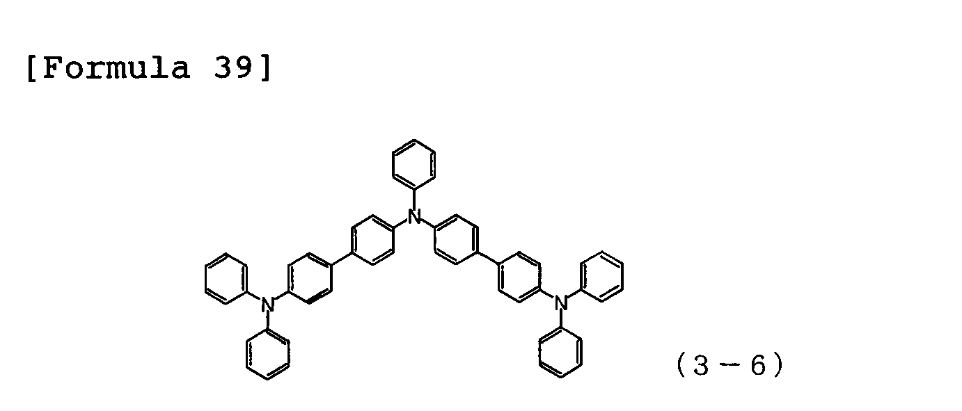
- An organic EL device was produced in the same manner as in Example 3, except that Compound 3-6 having the structural formula shown below was formed as the hole injection layer 3 in a film thickness of 20 nm in place of Compound 3-1.
- the characteristics of the organic EL device produced were measured by applying a direct current voltage thereto at room temperature in air. As a result, driving voltage when current density of 10 mA/cm 2 was passed was 3.95V.
- An organic EL device was produced in the same manner as in Example 3, except that Compound 3-14 having the structural formula shown below was formed as the hole injection layer 3 in a film thickness of 20 nm in place of Compound 3-1.
- the characteristics of the organic EL device produced were measured by applying a direct current voltage thereto at room temperature in air. As a result, driving voltage when current density of 10 mA/cm 2 was passed was 3.88V.
- An organic EL device was produced in the same manner as in Example 3, except that Compound 3-15 having the structural formula shown below was formed as the hole injection layer 3 in a film thickness of 20 nm in place of Compound 3-1.
- the characteristics of the organic EL device produced were measured by applying a direct current voltage thereto at room temperature in air. As a result, driving voltage when current density of 10 mA/cm 2 was passed was 3.85V.
- An organic EL device was produced in the same manner as in Example 3, except that Compound 4-4 having the structural formula shown below was formed as the hole transport layer 4 in a film thickness of 40 nm in place of Compound 4-1.
- the characteristics of the organic EL device produced were measured by applying a direct current voltage thereto at room temperature in air. As a result, driving voltage when current density of 10 mA/cm 2 was passed was 3.74V.
- An organic EL device was produced in the same manner as in Example 3, except that Compound 4-6 having the structural formula shown below was formed as the hole transport layer 4 in a film thickness of 40 nm in place of Compound 4-1.
- the characteristics of the organic EL device produced were measured by applying a direct current voltage thereto at room temperature in air. As a result, driving voltage when current density of 10 mA/cm 2 was passed was 3.82V.
- An organic EL device was produced in the same manner as in Example 3, except that Compound 4-9 having the structural formula shown below was formed as the hole transport layer 4 in a film thickness of 40 nm in place of Compound 4-1.
- the characteristics of the organic EL device produced were measured by applying a direct current voltage thereto at room temperature in air. As a result, driving voltage when current density of 10 mA/cm 2 was passed was 3.81V.
- An organic EL device was produced in the same manner as in Example 3, except that Compound 4-13 having the structural formula shown below was formed as the hole transport layer 4 in a film thickness of 40 nm in place of Compound 4-1.
- the characteristics of the organic EL device produced were measured by applying a direct current voltage thereto at room temperature in air. As a result, driving voltage when current density of 10 mA/cm 2 was passed was 3.76V.
- An organic EL device was produced in the same manner as in Example 3, except that Alq was formed as the electron transport layer 7 in a film thickness of 30 nm in place of Compound 1-8.
- the characteristics of the organic EL device produced were measured by applying a direct current voltage thereto at room temperature in air. As a result, driving voltage when current density of 10 mA/cm 2 was passed was 5.43V.
- An organic EL device was produced in the same manner as in Comparative Example 1, except that CuPc was formed as the hole injection layer 3 in a film thickness of 20 nm in place of Compound 3-1.
- the characteristics of the organic EL device produced were measured by applying a direct current voltage thereto at room temperature in air. As a result, driving voltage when current density of 10 mA/cm 2 was passed was 8.30V.
- the organic EL device of the present invention improves carrier balance in the inside of the organic EL device, and can realize an organic EL device having low driving voltage and long life, as compared with the conventional organic EL devices using CuPc and Alq.
- the organic EL device of the present invention comprising the combination of a specific arylamine compound and a specific pyridine derivative improves luminous efficiency and decreases driving voltage, and therefore can improve durability of an organic EL device. This enabled the organic EL device to expand to applications of, for example, home appliances and lightings.
Landscapes
- Chemical & Material Sciences (AREA)
- Physics & Mathematics (AREA)
- Organic Chemistry (AREA)
- Spectroscopy & Molecular Physics (AREA)
- Engineering & Computer Science (AREA)
- Materials Engineering (AREA)
- Optics & Photonics (AREA)
- Electroluminescent Light Sources (AREA)
- Pyridine Compounds (AREA)
- Plural Heterocyclic Compounds (AREA)
- Organic Low-Molecular-Weight Compounds And Preparation Thereof (AREA)
Abstract


Description
- The present invention relates to an organic electroluminescent device that is a self-emitting device suitable for various display devices. In more detail, the invention relates to an organic electroluminescent device (hereinafter referred to as an "organic EL device" for simplicity) comprising an arylamine derivative and a pyridine derivative.
- An organic EL device is a self-emitting device. Therefore, the organic EL device is bright, has excellent visibility and enables vivid display, as compared with liquid crystal devices. For this reason, active studies have been made on the organic EL device.
- In 1987, C. W. Tang et al. of Eastman Kodak developed a laminated structure device in which the constituent materials share various roles, and have put an organic EL device comprising an organic material into practical use. They laminated a fluorescent material capable of transporting electrons and an organic material capable of transporting holes, injected both charges into a fluorescent material layer, for light emission, and obtained high brightness of 1,000 cd/m2 or more at a voltage of 10V or lower (see, for example,
Patent Reference 1 and Patent Reference 2). -
- Patent Reference 1:
JP-A-8-48656 - Patent Reference 2: Japanese Patent No.
3194657 - Up to the present, various improvements have been made for the practical use of organic EL devices, an electroluminescent device has come to attain high efficiency and durability, in which various roles of the laminated structure are further subdivided to provide an anode, a hole injection layer, a hole transport layer, a light emitting layer, an electron transport layer, an electron injection layer and a cathode in this order on a substrate (see, for example, Non-Patent Reference 1).
-
- Non-Patent Reference 1: The Japan Society of Applied Physics, 9th Seminar, Preprint, pages 55-61 (2001)
- Use of a triplet exciton has been tried for the purpose of further improvement of luminous efficiency, and use of a phosphorescence-emitting compound is being investigated (see, for example, Non-Patent Reference 2).
-
- Non-Patent Reference 2: The Japan Society of Applied Physics, 9th Seminar, Preprint, pages 23-31 (2001)
- A light emitting layer can be produced by doping a charge-transporting compound generally referred to as a host material with a fluorescent compound or a phosphorescence-emitting compound. As described in the above Non-Patent Reference, the selection of organic materials in organic EL devices gives large influence to various characteristics, such as efficiency and durability, of the devices (see Non-Patent Reference 2).
- In an organic EL device, charges injected from both electrodes are recombined in the light emitting layer to emit light. To prepare an organic EL device having high efficiency, low driving voltage and long life, a device having excellent carrier balance in which electrons and holes were efficiently injected/transported, and recombined has to be formed.
- In the early stages, phthalocyanines such as copper phthalocyanine (hereinafter referred to "CuPc" for simplicity) were proposed as a hole injection material used in an organic EL device (see, for example, Patent Reference 3). However, because absorption is present in a visible region, materials having a phenylene diamine structure became to be widely used (see, for example, Patent Reference 4). On the other hand, arylamine materials containing a benzidine skeleton have been used as a hole transport material (see, for example, Patent Reference 5).
-
- Patent Reference 3:
US Patent No, 4,720,432 - Patent Reference 4:
JP-A-8-291115 - Patent Reference 5: Japanese Patent No.
3529735 - A typical light emitting material, tris(8-hydroxyquinoline)aluminum (hereinafter abbreviated as "Alq"), is generally used as an electron transport material. However, electron mobility of Alq is lower than hole mobility of a hole transport material generally used, and work function of Alq is 5.8 eV, thus not saying that the material has sufficient hole blocking ability. As a result, a part of holes passes through the light emitting layer, resulting in decrease in efficiency.
- To efficiently perform hole injection or electron injection from an anode and a cathode to a light emitting layer, a device in which a value of ionization potential and a value of electron affinity, of a material are stepwise set and at least two layers of the hole injection layer and the electron injection layer, respectively are laminated, is developed (see, for example, Patent Reference 6). However, it does not say that a material used is sufficient in each of luminous efficiency, driving voltage and device life.
-
- Patent Reference 6:
JP-A-6-314594 - To improve device characteristics of an organic EL device, a device having high efficiency, low driving voltage and long life is required, which has good carrier balance by combining materials being excellent in hole and electron injection/transport performances, stability as a thin film and durability.
- An object of the present invention is to provide an organic EL device having high efficiency, low driving voltage and long life by combining various materials for an organic EL device, being excellent in hole and election injection/transport performances, stability as a thin film and durability. The physical characteristics of the organic compound suitable to the present invention are that the compound has (1) good hole and electron injection characteristics, (2) high hole and electron mobility, (3) excellent electron and hole blocking abilities, (4) stable condition of a thin film, and is (5) excellent in heat resistance. The physical characteristics of the device suitable to the present invention are that the device has (1) a high luminous efficiency, (2)a low turn on voltage, (3) a low practical driving voltage, and (4)a long life.
- To achieve the above object, the present inventors have noted that an arylamine material is excellent in hole injection and transport abilities, stability as a thin film, and durability, and an electron-affinic pyridine derivative is excellent in electron injection and transporting abilities, stability as a thin film, and durability, have selected a specific arylamine compound and a specific pyridine derivative, and have produced various organic EL devices by combining those compounds in good carrier balance. They have intensively conducted characteristic evaluations of devices, and as a result, have completed the present invention.
- Specifically, according to the present invention, the following organic EL devices are provided.
- 1. An organic electroluminescent device comprising at least an anode electrode, a hole injection layer, a hole transport layer, a light emitting layer, an electron transport layer and a cathode electrode in this order, wherein the hole injection layer comprises an arylamine compound having at least three triphenylamine structures in the molecule, the hole transport layer comprises an arylamine compound having two triphenylamine structures in the molecule, and the electron transport layer comprises a substituted bipyridyl compound represented by the following general formula (1):
-

- wherein R1 to R7 may be the same or different, and each represents a hydrogen atom, a fluorine atom, a chlorine atom, a cyano group, a trifluoromethyl group, a linear or branched alkyl group having from 1 to 6 carbon atoms, a substituted or unsubstituted aromatic hydrocarbon group, a substituted or unsubstituted aromatic heterocyclic group, or a substituted or unsubstituted condensed polycyclic aromatic group; n1 is an integer of from 2 to 4; A1 represents a di- to tetra-valent substituted or unsubstituted aromatic hydrocarbon group, a di- to tetra-valent substituted or unsubstituted aromatic heterocyclic group, a di- to tetra-valent substituted or unsubstituted condensed polycyclic aromatic group or a trivalent group represented by the following general formula (2):
-

- wherein X, Y and Z each represents a carbon atom or a nitrogen atom, provided that when n1 = 2, two bipyridyl structures can directly bond to each other, and in that case, A1 is absent.
- 2. The organic EL device described in 1 above, wherein the arylamine compound having at least three triphenylamine structures in the molecule and contained in the hole injection layer is an arylamine compound represented by the following general formula (3):
-

- wherein R8 to R19 may be the same or different, and each represents a fluorine atom, a chlorine atom, a cyano group, a trifluoromethyl group, a linear or branched alkyl group having from 1 to 6 carbon atoms, a linear or branched alkenyl group having from 1 to 6 carbon atoms, a substituted or unsubstituted aromatic hydrocarbon group, a substituted or unsubstituted aromatic heterocyclic group, or a substituted or unsubstituted condensed polycyclic aromatic group, provided that when a plurality of those substituents bond to the same benzene ring, those substituents may be combined to form a ring; r8 to r19 are 0 or an integer of from 1 to 4; and A2, A3 and A4 may be the same or different, and each represents a divalent group represented by the following structural formulae (B) to (F), or a single bond:
-

- wherein n2 is an integer of from 1 to 3.
-

-

-
[Formula 7] ―CH2― (E)
-

- 3. The organic EL device described in 1 or 2 above, wherein the arylamine compound having two triphenylamine structures in the molecule and contained in the hole transport layer is an arylamine compound represented by the following general formula (4):
-
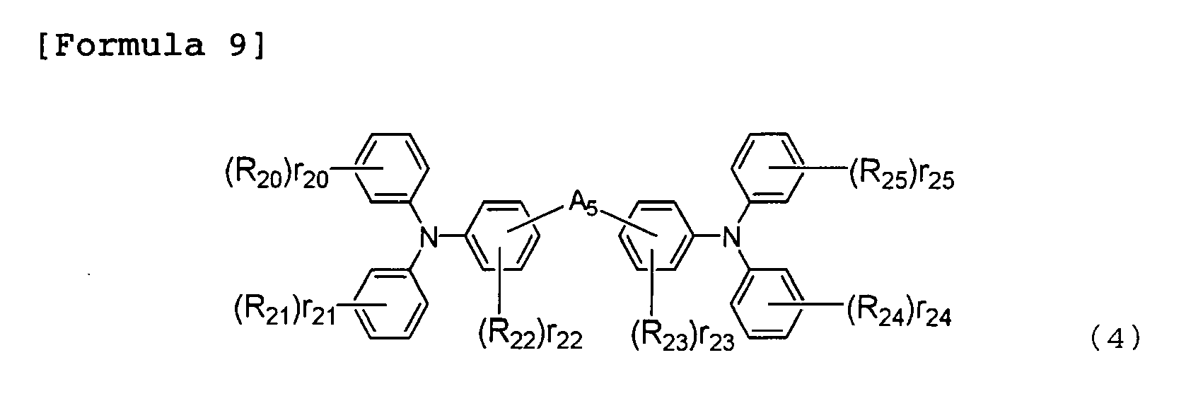
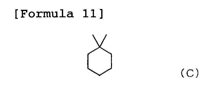
- wherein R20 to R25 may be the same or different, and each represents a fluorine atom, a chlorine atom, a cyano group, a trifluoromethyl group, a linear or branched alkyl group having from 1 to 6 carbon atoms, a linear or branched alkenyl group having from 1 to 6 carbon atoms, a substituted or unsubstituted aromatic hydrocarbon group, a substituted or unsubstituted aromatic heterocyclic group, or a substituted or unsubstituted condensed polycyclic aromatic group, provided that when a plurality of those substituents are bonded to the same benzene ring, those substituents may be combined to form a ring; r20 to r25 are 0 or an integer of from 1 to 4; and A5 represents a divalent group represented by the following structural formulae (B) to (F), or a single bond:
-

- wherein n2 is an integer of from 1 to 3.
-
-

-
[Formula 13] ―CH2― (E)
-

- 4. The organic EL device described in any one of 1 to 3 above, wherein the substituted bipyridyl compound is an arylamine compound represented by the following general formula (5):
-

- wherein R26 to R32 may be the same or different, and each represents a hydrogen atom, a fluorine atom, a chlorine atom, a cyano group, a trifluoromethyl group, a linear or branched alkyl group having from 1 to 6 carbon atoms, a substituted or unsubstituted aromatic hydrocarbon group, a substituted or unsubstituted aromatic heterocyclic group, or a substituted or unsubstituted condensed polycyclic aromatic group; n3 is an integer of 3 or 4; and A6 represents a tri- or tetra-valent substituted or unsubstituted aromatic hydrocarbon group, a tri-or tetra-valentsubstituted or unsubstituted aromatic heterocyclic group, or a tri- or tetra-valent substituted or unsubstituted condensed polycyclic aromatic group.
- The aromatic hydrocarbon group, the aromatic heterocyclic group or the condensed polycyclic aromatic group of the substituted or unsubstituted aromatic hydrocarbon group, the substituted or unsubstituted aromatic heterocyclic group or the substituted or unsubstituted condensed polycyclic aromatic group, for A1 in the general formula (1) specifically include the following groups. One to three hydrogen atoms are further reduced from those groups to form di- to tetra-valent groups. A phenyl group, a biphenylyl group, a terphenylyl group, a tetrakisphenyl group, a styryl group, a naphthyl group, an anthryl group, an acenaphthenyl group, a fluorenyl group, a phenanthryl group, a pyrenyl group, a pyridyl group, a pyrimidyl group, a triazine group, a furanyl group, a pyranyl group, a thienyl group, a quinolyl group, a benzofuranyl group, a benzothienyl group, an indolyl group, a carbazolyl group, a benzoxazolyl group, a benzothiazolyl group, a quinoxalyl group, a benzimidazolyl group, a pyrazolyl group, a dibenzofuranyl group, a dibenzothienyl group, a naphthyridinyl group and a phenantrolyl group.
- The substituents for the substituted or unsubstituted aromatic hydrocarbon group, the substituted or unsubstituted aromatic heterocyclic group or the substituted or unsubstituted condensed polycyclic aromatic group, for A1 in the general formula (1) specifically include a fluorine atom, a chlorine atom, a cyano group, a hydroxyl group, a nitro group, and a linear or branched alkyl group having from 1 to 6 carbon atoms. Those substituents may further be substituted.
- The aromatic hydrocarbon groups of the substituted or unsubstituted aromatic hydrocarbon group, the substituted or unsubstituted aromatic heterocyclic group or the substituted or unsubstituted condensed polycyclic aromatic group, for R1 to R7 in the general formula (1) specifically include a phenyl group, abiphenylylgroup, aterphenylylgroup, atetrakisphenyl group, a styryl group, a naphthyl group, an anthryl group, an acenaphthenyl group, a fluorenyl group, a phenanthryl group, an indenyl group, a pyrenyl group, a pyridyl group, a bipyridyl group, a pyrimidyl group, a furanyl group, a pyranyl group, a thienyl group, a quinolyl group, an isoquinolyl group, a benzofuranyl group, a benzothienyl group, an indolyl group, acarbazolylgroup, abenzoxazolylgroup, abenzothiazolylgroup, a quinoxalyl group, a benzimidazolyl group, a pyrazolyl group, a dibenzofuranyl group, a dibenzothienyl group, a naphthyridinyl group, a phenanthrolinyl group and an acrydinyl group.
- The substituents for the substituted or unsubstituted aromatic hydrocarbon group, the substituted or unsubstituted aromatic heterocyclic group or the substituted or unsubstituted condensed polycyclic aromatic group, for R1 to R7 in the general formula (1) specifically include a fluorine atom, a chlorine atom, a trifluoromethyl group, a linear or branched alkyl group having from 1 to 6 carbon atoms, a phenyl group, a biphenylyl group, a terphenylyl group, a tetrakisphenyl group, a styryl group, a naphthyl group, afluorenylgroup, a phenanthryl group, an indenyl group, a pyrenyl group, a pyridyl group, a bipyridyl group, apyrimidylgroup, a quinolyl group, an isoquinolyl group, an indolyl group, a carbazolyl group, a quinoxalyl group and a pyrazolyl group. Those substituents may further be substituted.
- The aromatic hydrocarbon group, the aromatic heterocyclic group or the condensed polycyclic aromatic group of the substituted or unsubstituted aromatic hydrocarbon group, the substituted or unsubstituted aromatic heterocyclic group or the substituted or unsubstituted condensed polycyclic aromatic group, for R8 to R19 in the general formula (3) specifically include a phenyl group, a biphenylyl group, a terphenylyl group, a tetrakisphenyl group, a styryl group, a naphthyl group, an anthryl group, an acenaphthenyl group, a fluorenyl group, aphenanthrylgroup, an indenyl group, a pyrenyl group, a pyridyl group, a pyrimidyl group, a furanyl group, a pyranyl group, a thienyl group, a quinolyl group, an isoquinolyl group, a benzofuranyl group, a benzothienyl group, an indolyl group, a carbazolyl group, a benzoxazolyl group, a benzothiazolyl group, a quinoxalyl group, a benzimidazolyl group, a pyrazolyl group, a dibenzofuranyl group, a dibenzothienyl group, a naphthyridinyl group, a phenanthrolinyl group and an acrydinyl group.
- The substituents for the substituted or unsubstituted aromatic hydrocarbon group, the substituted or unsubstituted aromatic heterocyclic group or the substituted or unsubstituted condensed polycyclic aromatic group, for R8 to R19 in the general formula (3) specifically include a fluorine atom, a chlorine atom, a trifluoromethyl group, a linear or branched alkyl group having from 1 to 6 carbon atoms, a phenyl group, a biphenylyl group, a terphenylyl group, a tetrakisphenyl group, a styryl group, a naphthyl group, afluorenylgroup, aphenanthrylgroup, an indenyl group and a pyrenyl group. Those substituents may further be substituted.
- The aromatic hydrocarbon group, the aromatic heterocyclic group or the condensed polycyclic aromatic group of the substituted or unsubstituted aromatic hydrocarbon group, the substituted or unsubstituted aromatic heterocyclic group or the substituted or unsubstituted condensed polycyclic aromatic group, for R20 to R25 in the general formula (4) specifically include a phenyl group, a biphenylyl group, a terphenylyl group, a tetrakisphenyl group, a styryl group, a naphthyl group, an anthryl group, an acenaphthenyl group, a fluorenyl group, aphenanthrylgroup, an indenyl group, a pyrenyl group, a pyridyl group, a pyrimidyl group, a furanyl group, a pyranyl group, a thienyl group, a quinolyl group, an isoquinolyl group, a benzofuranyl group, a benzothienyl group, an indolyl group, a carbazolyl group, a benzoxazolyl group, a benzothiazolyl group, a quinoxalyl group, a benzimidazolyl group, a pyrazolyl group, a dibenzofuranyl group, a dibenzothienyl group, a naphthyridinyl group, a phenanthrolinyl group and acrydinyl group.
- The substituents for the substituted or unsubstituted aromatic hydrocarbon group, the substituted or unsubstituted aromatic heterocyclic group or the substituted or unsubstituted condensed polycyclic aromatic group, for R20 to R25 in the general formula (4) specifically include a fluorine atom, a chlorine atom, a trifluoromethyl group, a linear or branched alkyl group having from 1 to 6 carbon atoms, a phenyl group, a biphenylyl group, a terphenylyl group, a tetrakisphenyl group, a styryl group, a naphthyl group, a fluorenyl group, a phenanthryl group, an indenyl group and a pyrenyl group. Those substituents may further be substituted.
- The aromatic hydrocarbon group, the aromatic heterocyclic group or the condensed polycyclic aromatic group of the substituted or unsubstituted aromatic hydrocarbon group, the substituted or unsubstituted aromatic heterocyclic group or the substituted or unsubstituted condensed polycyclic aromatic group, for A6 in the general formula (5) specifically include the following groups. Two or three hydrogen atoms are further reduced from those groups to form tri- or tetra-valent groups. A phenyl group, a biphenylyl group, a terphenylyl group, a tetrakisphenyl group, a styryl group, a naphthyl group, an anthryl group, an acenaphthenyl group, a fluorenyl group, a phenanthryl group, a pyrenyl group, a pyridyl group, a pyrimidyl group, a triazine group, a furanyl group, a pyranyl group, a thienyl group, a quinolyl group, a benzofuranyl group, a benzothienyl group, an indolyl group, a carbazolyl group, a benzoxazolyl group, a benzothiazolyl group, a quinoxalyl group, a benzimidazolyl group, a pyrazolyl group, a dibenzofuranyl group, a dibenzothienyl group, a naphthyridinyl group and a phenantrolyl group.
- The substituents for the substituted or unsubstituted aromatic hydrocarbon group, the substituted or unsubstituted aromatic heterocyclic group or the substituted or unsubstituted condensed polycyclic aromatic group, for A6 in the general formula (5) specifically include a fluorine atom, a chlorine atom, a cyano group, a hydroxyl group, a nitro group, and a linear or branched alkyl group having from 1 to 6 carbon atoms. Those substituents may further be substituted.
- The substituted bipyridyl compound represented by the above general formula (1) or (5), used in the organic EL device of the present invention can be used as a constituent material for the electron transport layer of the organic EL device.
The arylamine compound having at least three triphenylamine structures in the molecule represented by the above general formula (3) or the arylamine compound having two triphenylamine structures in the molecule represented by the above general formula (4), used in the organic EL device of the present invention can be used as a constituent material for the hole injection layer or the hole transport layer of the organic EL device.
The arylamine compound having at least three triphenylamine structures in the molecule represented by the above general formula (3) has high hole mobility as compared with the arylamine compound having two triphenylamine structures in the molecule represented by the above general formula (4), and is therefore a preferred compound as a material for the hole injection layer. - The organic EL device of the present invention combines materials for an organic EL device, having excellent hole and election injection/transport performances, stability as a thin film and durability, taking carrier balance into consideration. Therefore, as compared with the conventional organic EL devices, hole transport efficiency to the hole transport layer is improved, and electron transport efficiency to the light emitting layer from the electron transport layer is improved. As a result, luminous efficiency is improved and driving voltage is decreased, thereby durability of the organic EL device can be improved.
Thus, an organic EL device having high efficiency, low driving voltage and long life can be attained in the present invention. - The organic EL device of the present invention can realize an organic EL device having high efficiency, low driving voltage and long life by selecting a specific arylamine compound and a specific pyridine derivative which have excellent hole and election injection/transport performances, stability as a thin film and durability, and combining those compounds so as to achieve good carrier balance. The organic EL device of the present invention can improve luminous efficiency, driving voltage and durability of the conventional organic EL devices.
- The substituted bipyridyl compound represented by the above general formula (1) or (5) used in the organic EL device of the present invention can be produced by, for example, conducting a cross-coupling reaction such as Suzuki coupling (see, for example, Non-Patent Reference 4) between a boronic acid or a borate that is produced through the reaction between halides of various aromatic hydrocarbon compounds, condensed polycyclic aromatic compounds or aromatic heterocyclic compounds and pinacol borane or bis(pinacolato)diboron (see, for example, Non-Patent Reference 3), and various halogenopyridines.
-
- Non-Patent Reference 3: J. Org. Chem., 60, 7508 (1995)
- Non-Patent Reference 4: Synth. Commun., 11, 513 (1981)
- The arylamine compound having at least three triphenylamine structures in the molecule represented by the above general formula (3) or the arylamine compound having two triphenylamine structures in the molecule represented by the above general formula (4), used in the organic EL device of the present invention can be produced by the conventional methods (see, for example, Patent References 7 to 9).
-
- Patent Reference 7:
JP-A-7-126615 - Patent Reference 8:
JP-A-8-048656 - Patent Reference 9:
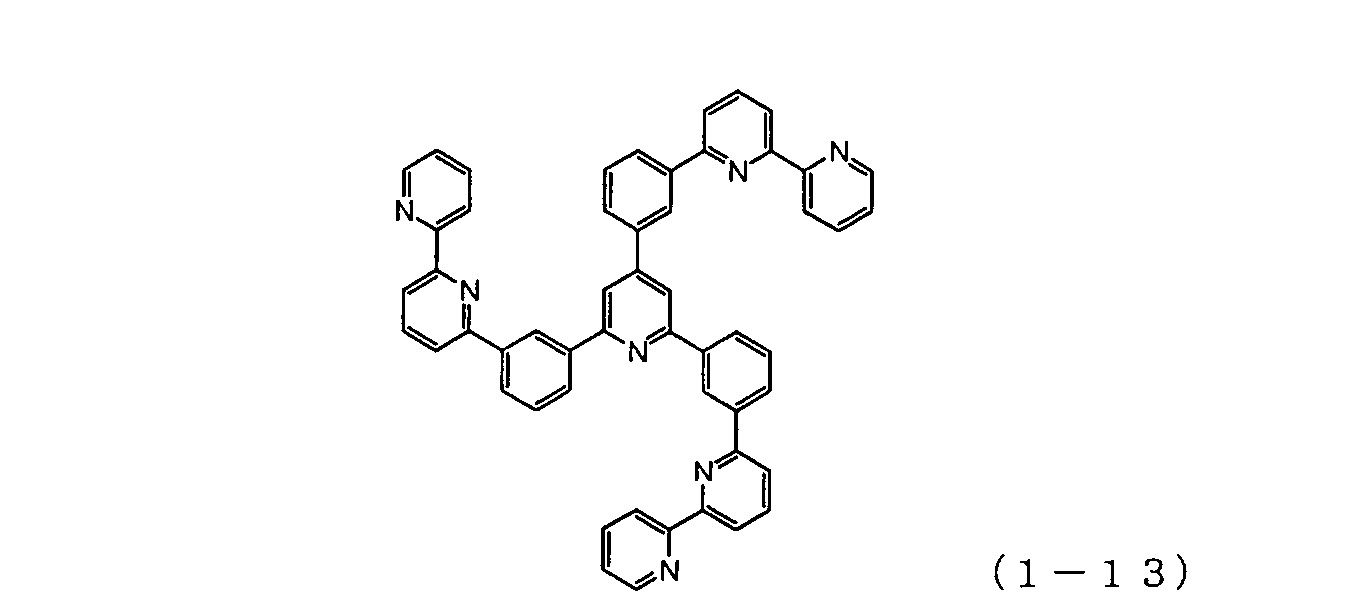
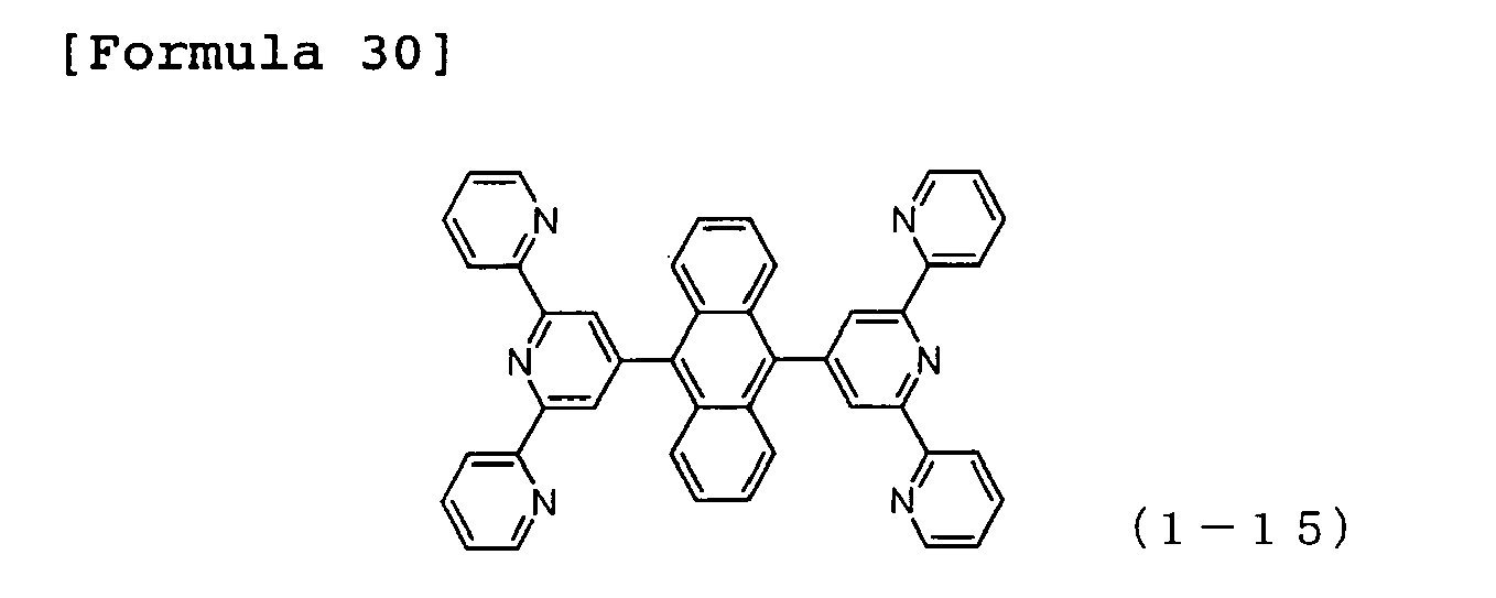
JP-A-2005-108804 - Specific examples of the preferred compounds of the substituted bipyridyl compounds represented by the general formula (1) used in the organic EL device of the present invention are described below, but the invention is not construed as being limited to those compounds.
-

-

-

-


-

-

-


-

-

-


- 1

-

-

-

-
-

-


-

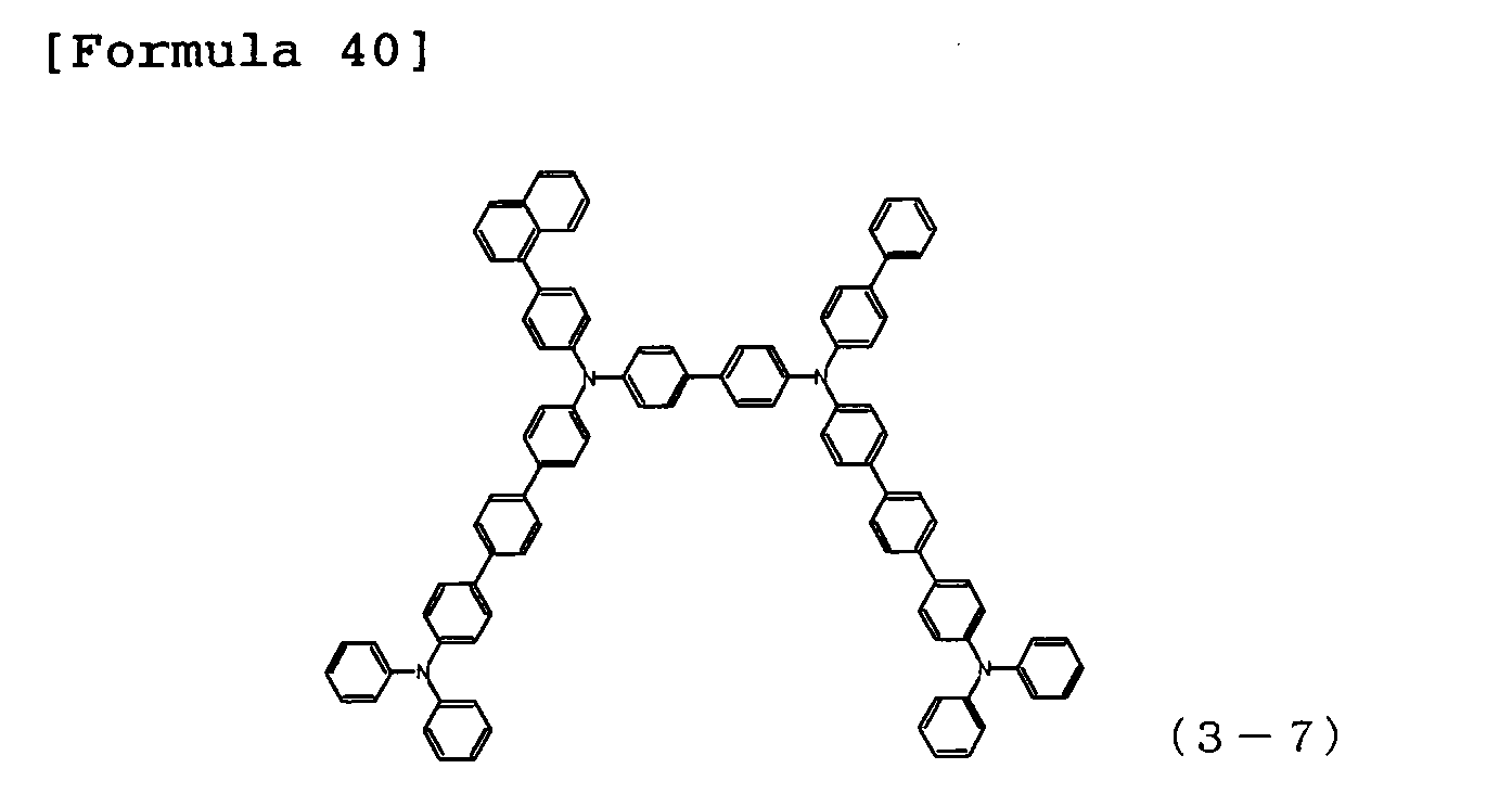
- Specific examples of the preferred compounds of the arylamine compounds having at least three triphenylamine structures in the molecule represented by the general formula (3) used in the organic EL device of the present invention are described below, but the invention is not construed as being limited to those compounds.
-

-

-

-

-

-
-
-

-


-

-

-

-

-

-

- Specific examples of the preferred compounds of the arylamine compounds having two triphenylamine structures in the molecule represented by the general formula (4) used in the organic EL device of the present invention are described below, but the invention is not construed as being limited to those compounds.
-

-

-

-


-

-

-

-

-

-

-


-

-

- The structure of the organic EL device of the present invention includes a structure comprising a
glass substrate 1 having formed thereon an anode (transparent electrode) 2, a hole injection layer 3, a hole transport layer 4, alight emitting layer 5, anelectron transport layer 7, anelectron injection layer 8 and acathode 9 in this order, as shown inFig. 2 , and a structure further having a hole blocking layer 6 between the light emittinglayer 5 and theelectron transport layer 7, as shown inFig. 1 . In those multilayered structures, some organic layers can be omitted. For example, an anode, a hole injection layer, a hole transport layer, a light emitting layer, an electron transport layer and a cathode can be formed on a glass substrate in this order. - An electrode material having large work function, such as ITO or gold, is used as the anode of the organic EL device of the present invention.
An arylamine compound having high hole mobility and having at least three triphenylamine structures in the molecule is used as the hole injection layer.
An arylamine compound having two triphenylamine structures in the molecule is used as the hole transport layer. - Complexes of aluminum, styryl derivatives, thiazole derivatives, oxazole derivatives, carbazole derivatives, polydialkyl fluorene derivatives, and the like are used as the light emitting layer and the hole blocking layer of the organic EL device of the present invention.
The host material of the light emitting layer can use, for example, a fluorescent material such as quinacridone, coumarin or rubrene. The phosphorescence-emitting material uses green phosphorescence-emitting materials such as iridium complex of phenylpyridine (Ir(PPy)3), blue phosphorescence-emitting materials such as FIrpic and FIr6, and red phosphorescence-emitting materials such as Btp2Ir(acac). In this case, a high performance organic EL device can be produced by using, for example, hole injection/transporting host material 4,4'-di(N-carbazolyl)- biphenyl (hereinafter abbreviated as "CBP") as the host material. - The substituted bipyridyl compound can be used as the hole blocking layer of the organic EL device of the present invention.
- The substituted bipyridyl compound is used as the electron transport layer of the organic EL device of the present invention.
- The organic EL device of the present invention may have an electron injection layer as shown in
Figs. 1 and 2 . As for the electron injection layer, lithium fluoride and the like can be used.
As for the cathode, an electrode material having low work function, such as aluminum, or an electrode material of an alloy having lower work function, such as aluminum magnesium, can be used. - The embodiments of the present invention are specifically described with reference to the following Examples. However, the invention should not be limited to the following examples so long as it does not exceed the scope and the spirit thereof.
- In nitrogen atmosphere, 8.6 g of 1,3,5-tribromobenzene, 25.0 g of bis(pinacolato)diboron (PIN2B2), 24.1 g of potassium acetate, 250 ml of dimethyl sulfoxide previously dewatered with Molecular Sieves 4A, and 1.35 g of PdCl2(dppf)-CH2Cl2 were put in a reactor, and the resulting mixture was heated, followed by stirring at 80°C for 20 hours. After cooling to room temperature, the resulting reaction liquid was added to 1,000 ml of water, followed by stirring for 30 minutes. Precipitates were filtered off by filtration, and the precipitates were washed with methanol to obtain a crude product. The crude product obtained was dissolved in 200 ml of ethyl acetate, insoluble matters were removed by filtration, and the filtrate was concentrated to dryness. Thus, 7.1 g (yield: 57%) of a white powder, 1,3,5-tris(4,4,5,5-tetramethyl-[1,3,2]-dioxaborolane-2-yl)benzene, was obtained.
- 3.0 g of the 1,3,5-tris(4,4,5,5-tetramethyl-[1,3,2]-dioxaborolane-2-yl)benzene obtained, 6.2 g of 6-bromo-[2,2';6',2"]-terpyridine, 59.2 ml of 1M potassium carbonate aqueous solution, 0.39 g of tetrakis(triphenylphosphine)-palladium (0), 131 ml of toluene and 33 ml of ethanol were put in a reactor in nitrogen atmosphere, followed by heating under reflux while stirring for 18 hours. After cooling to room temperature, 100 ml of water and 100 ml of toluene were added to the reactor to perform liquid separation. An organic layer obtained was washed with 100 ml of water. The organic layer was dewatered with anhydrous magnesium sulfate, and then concentrated, thereby obtaining a crude product. The crude product was purified with column chromatography (carrier: NH silica gel, eluent:chloroform/n-hexane). Thus, 1. 8 g (yield: 35%) of a white powder, 1,3,5-tris(2,2';6',2"-terpyridine-6-yl)benzene (Compound 1-8) was obtained.
- 3,5,3',5'-tetrakis(4,4,5,5-tetramethyl-[1,3,2]-dioxaborolane-2-yl)biphenyl was produced from 3,5,3',5'-tetrabromobiphenyl and bis(pinacolato)diboron in the same manner as in Example 1 above. 3.2 g of the 3,5,3', 5' tetrakis - (4,4,5,5-tetramethyl-[1,3,2]dioxaborolane-2-yl)biphenyl obtained, 4.5 g of 6-bromo-2,2'-bipyridine, 28.7 ml of 2M potassium carbonate aqueous solution, 0.3 g of tetrakis-(triphenylphosphine)palladium (0), 110 ml of toluene and 25 ml of ethanol were put in a nitrogen-purged reactor, followed by heating under reflux while stirring for 22 hours. After cooling to room temperature, 100 ml of water and 300 ml of chloroform were added to the reactor to perform liquid separation. An organic layer obtained was washed with 100 ml of water. The organic layer was dewatered with anhydrous magnesium sulfate, and then concentrated, thereby obtaining a crude product. The crude product was purified with column chromatograph (carrier: NH silica gel, eluent: chloroform/n-hexane). Thus, 2.4 g (yield: 64%) of a white powder, 3,5,3',5'-tetrakis(2,2'-bipyridine-6-yl)biphenyl (Compound 1-18), was obtained.
- 2.5 g of the 1,3,5-tris(4,4,5,5-tetramethyl-[1,3,2]-dioxaborolane-2-yl) benzene obtained in Example 1, 3 . 8 g of 6-bromo-2,2' -bipyridine, 32.3 ml of 1M potassium carbonate aqueous solution, 0.32 g of tetrakis(triphenylphosphine)palladium (0), 108 ml of toluene and 27 ml of ethanol were put in a reactor in nitrogen atmosphere, followed by heating under reflux while stirring for 18 hours. After cooling to room temperature, 100 ml of water and 100 ml of toluene were added to the reactor to perform liquid separation. An organic layer obtained was washed with 100 ml of water. The organic layer was dewatered with anhydrous magnesium sulfate, and then concentrated, thereby obtaining a crude product. The crude product was purified with column chromatograph (carrier: NH silica gel, eluent: chloroform/n-hexane). Thus, 1.1 g (yield: 38%) of a white powder, 1,3,5-tris(2,2'-bipyridine-6-yl)benzene (Compound 1-2) was obtained.
- An organic EL device was produced by forming a hole injection layer 3, a hole transport layer 4, a
light emitting layer 5, anelectron transport layer 7, anelectron injection layer 8 and a cathode (aluminum electrode) 9 in this order by vapor deposition on aglass substrate 1 having previously formed thereon an ITO electrode as a transparent anode 2, as shown inFig. 2 . Theglass substrate 1 having formed thereon an ITO film having a thickness of 150 nm was subjected to ultrasonic cleaning in isopropyl alcohol for 20 minutes, and then subjected to boiling washing on a hot plate heated to 150°C for 20 minutes. The ITO-attached glass substrate was set in a vacuum deposition chamber. After conducting oxygen plasma treatment for 5 minutes, pressure was reduced to 0.001 Pa or less. - Subsequently, Compound 3-1 having the structural formula shown below was formed as the hole injection layer 3 in a film thickness of 20 nm so as to cover the transparent electrode 2. Compound 4-1 having the structural formula shown below was formed as the hole transport layer 4 on the hole injection layer 3 in a film thickness of 40 nm. Compound 6 having the structural formula shown below and
Compound 7 having the structural formula shown below were formed as thelight emitting layer 5 on the hole transport layer 4 in a film thickness of 30 nm by conducting binary vapor deposition in such a vapor deposition rate that vapor deposition rate ratio is Compound 6 :Compound 7 = 5:95. Compound 1-8 having the structural formula shown belowwas formed as theelectron transport layer 7 on thelight emitting layer 5 in a film thickness of 30 nm. Lithium fluoride was formed as theelectron injection layer 8 on theelectron transport layer 7 in a film thickness of 0.5 nm. Finally, aluminum was vapor deposited in a thickness of 150 nm to form thecathode 9.
The characteristics of the organic EL device produced were measured by applying a direct current voltage thereto at room temperature in air. As a result, driving voltage when current density of 10 mA/cm2 was passed through the organic EL device was 3.70V. -

-

-

-

-

- An organic EL device was produced in the same manner as in Example 3, except that Compound 1-2 having the structural formula shown below was formed as the
electron transport layer 7 in a film thickness of 30 nm in place of Compound 1-8.
The characteristics of the organic EL device produced were measured by applying a direct current voltage thereto at room temperature in air. As a result, driving voltage when current density of 10 mA/cm2 was passed was 3.68V. -

- An organic EL device was produced in the same manner as in Example 3, except that Compound 1-3 having the structural formula shown below was formed as the
electron transport layer 7 in a film thickness of 30 nm in place of Compound 1-8.
The characteristics of the organic EL device produced were measured by applying a direct current voltage thereto at room temperature in air. As a result, driving voltage when current density of 10 mA/cm2 was passed was 3.78V. -

- An organic EL device was produced in the same manner as in Example 3, except that Compound 1-6 having the structural formula shown below was formed as the
electron transport layer 7 in a film thickness of 30 nm in place of Compound 1-8.
The characteristics of the organic EL device produced were measured by applying a direct current voltage thereto at room temperature in air. As a result, driving voltage when current density of 10 mA/cm2 was passed was 3.73V. -

- An organic EL device was produced in the same manner as in Example 3, except that Compound 1-18 having the structural formula shown below was formed as the
electron transport layer 7 in a film thickness of 30 nm in place of Compound 1-8.
The characteristics of the organic EL device produced were measured by applying a direct current voltage thereto at room temperature in air. As a result, driving voltage when current density of 10 mA/cm2 was passed was 3.75V. -

- An organic EL device was produced in the same manner as in Example 3, except that Compound 3-4 having the structural formula shown below was formed as the hole injection layer 3 in a film thickness of 20 nm in place of Compound 3-1.
The characteristics of the organic EL device produced were measured by applying a direct current voltage thereto at room temperature in air. As a result, driving voltage when current density of 10 mA/cm2 was passed was 3.77V. -

- An organic EL device was produced in the same manner as in Example 3, except that Compound 3-6 having the structural formula shown below was formed as the hole injection layer 3 in a film thickness of 20 nm in place of Compound 3-1.
The characteristics of the organic EL device produced were measured by applying a direct current voltage thereto at room temperature in air. As a result, driving voltage when current density of 10 mA/cm2 was passed was 3.95V. -

- An organic EL device was produced in the same manner as in Example 3, except that Compound 3-14 having the structural formula shown below was formed as the hole injection layer 3 in a film thickness of 20 nm in place of Compound 3-1.
The characteristics of the organic EL device produced were measured by applying a direct current voltage thereto at room temperature in air. As a result, driving voltage when current density of 10 mA/cm2 was passed was 3.88V. -

- An organic EL device was produced in the same manner as in Example 3, except that Compound 3-15 having the structural formula shown below was formed as the hole injection layer 3 in a film thickness of 20 nm in place of Compound 3-1.
The characteristics of the organic EL device produced were measured by applying a direct current voltage thereto at room temperature in air. As a result, driving voltage when current density of 10 mA/cm2 was passed was 3.85V. -

- An organic EL device was produced in the same manner as in Example 3, except that Compound 4-4 having the structural formula shown below was formed as the hole transport layer 4 in a film thickness of 40 nm in place of Compound 4-1.
The characteristics of the organic EL device produced were measured by applying a direct current voltage thereto at room temperature in air. As a result, driving voltage when current density of 10 mA/cm2 was passed was 3.74V. -


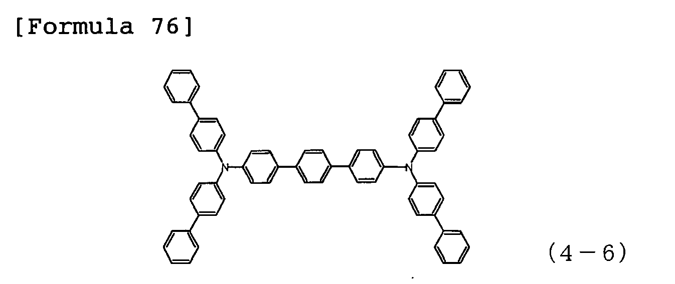
- An organic EL device was produced in the same manner as in Example 3, except that Compound 4-6 having the structural formula shown below was formed as the hole transport layer 4 in a film thickness of 40 nm in place of Compound 4-1.
The characteristics of the organic EL device produced were measured by applying a direct current voltage thereto at room temperature in air. As a result, driving voltage when current density of 10 mA/cm2 was passed was 3.82V. -
- An organic EL device was produced in the same manner as in Example 3, except that Compound 4-9 having the structural formula shown below was formed as the hole transport layer 4 in a film thickness of 40 nm in place of Compound 4-1.
The characteristics of the organic EL device produced were measured by applying a direct current voltage thereto at room temperature in air. As a result, driving voltage when current density of 10 mA/cm2 was passed was 3.81V. -

- An organic EL device was produced in the same manner as in Example 3, except that Compound 4-13 having the structural formula shown below was formed as the hole transport layer 4 in a film thickness of 40 nm in place of Compound 4-1.
The characteristics of the organic EL device produced were measured by applying a direct current voltage thereto at room temperature in air. As a result, driving voltage when current density of 10 mA/cm2 was passed was 3.76V. -


- An organic EL device was produced in the same manner as in Example 3, except that Alq was formed as the
electron transport layer 7 in a film thickness of 30 nm in place of Compound 1-8.
The characteristics of the organic EL device produced were measured by applying a direct current voltage thereto at room temperature in air. As a result, driving voltage when current density of 10 mA/cm2 was passed was 5.43V. - An organic EL device was produced in the same manner as in Comparative Example 1, except that CuPc was formed as the hole injection layer 3 in a film thickness of 20 nm in place of Compound 3-1.
The characteristics of the organic EL device produced were measured by applying a direct current voltage thereto at room temperature in air. As a result, driving voltage when current density of 10 mA/cm2 was passed was 8.30V. - From Comparative Example 1 and Comparative Example 2, when the compound of the hole injection layer is changed from CuPc to Compound 3-1, the driving voltage was decreased from 8. 30V to 5.43V. Additionally, when the compound of the electron transport layer is changed to the substituted bipyridyl compound (Compound 1-8) which is material of high transport rate of electron carrier, it could be confirmed that the driving voltage is greatly decreased to 3.70V as shown in Example 3. This indicates that when a material having high hole mobility is combined with a material having high electron carrier transport rate, carrier balance between hole carrier and electron carrier was improved.
- It was seen that by the combination of a specific arylamine compound and a specific substituted bipyridyl compound, the organic EL device of the present invention improves carrier balance in the inside of the organic EL device, and can realize an organic EL device having low driving voltage and long life, as compared with the conventional organic EL devices using CuPc and Alq.
- The organic EL device of the present invention, comprising the combination of a specific arylamine compound and a specific pyridine derivative improves luminous efficiency and decreases driving voltage, and therefore can improve durability of an organic EL device. This enabled the organic EL device to expand to applications of, for example, home appliances and lightings.
-
-
Fig. 1 is a view showing a constitution example of the EL device of the present invention. -
Fig. 2 is a view showing constitution of the EL device of the Examples. -
- 1
- Glass substrate
- 2
- Transparent anode
- 3
- Hole injection layer
- 4
- Hole transport layer
- 5
- Light emitting layer
- 6
- Hole blocking layer
- 7
- Electron transport layer
- 8
- Electron injection layer
- 9
- Cathode
Claims (4)
- An organic electroluminescent device comprising at least an anode electrode, a hole injection layer, a hole transport layer, a light emitting layer, an electron transport layer and a cathode electrode in this order, wherein the hole injection layer comprises an arylamine compound having at least three triphenylamine structures in the molecule, the hole transport layer comprises an arylamine compound having two triphenylamine structures in the molecule, and the electron transport layer comprises a substituted bipyridyl compound represented by the following general formula (1):


- The organic electroluminescent device as claimed in claim 1, wherein the arylamine compound having at least three triphenylamine structures in the molecule and contained in the hole injection layer is an arylamine compound represented by the following general formula (3):


- The organic electroluminescent device as claimed in claim 1 or 2, wherein the arylamine compound having two triphenylamine structures in the molecule and contained in the hole transport layer is an arylamine compound represented by the following general formula (4):
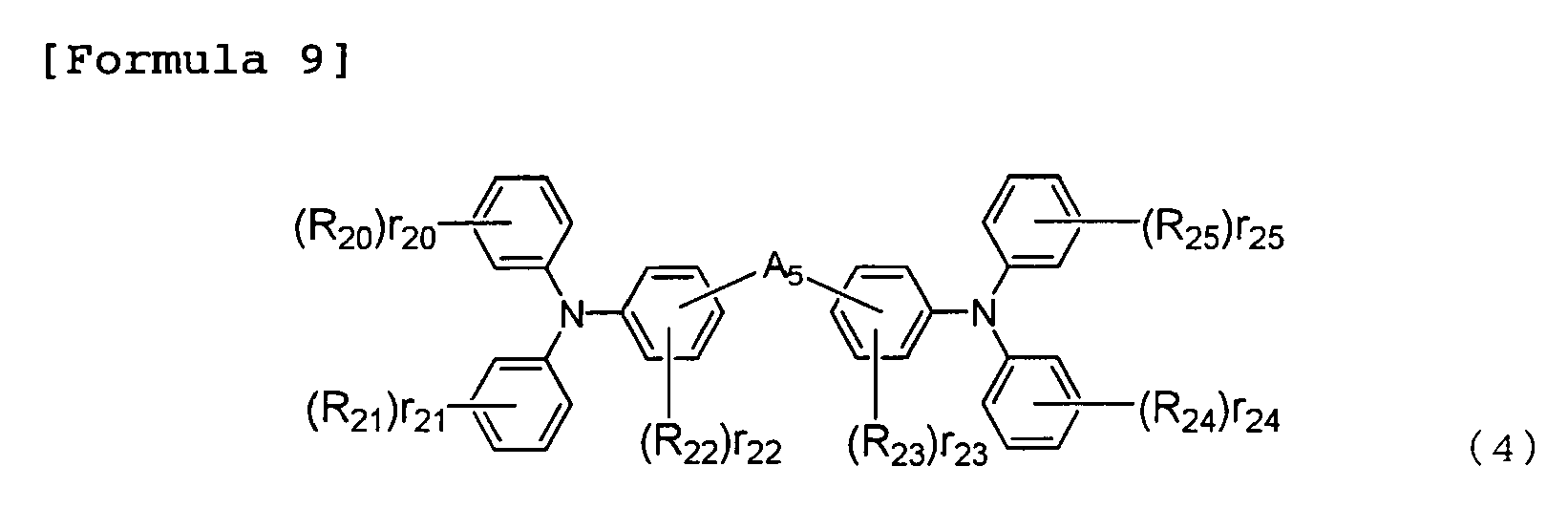


[Formula 13] -CH2- (E)

- The organic electroluminescent device as claimed in any one of claims 1 to 3, wherein the substituted bipyridyl compound is an arylamine compound represented by the following general formula (5):

Applications Claiming Priority (2)
| Application Number | Priority Date | Filing Date | Title |
|---|---|---|---|
| JP2008152473 | 2008-06-11 | ||
| PCT/JP2009/060490 WO2009151039A1 (en) | 2008-06-11 | 2009-06-09 | Organic electroluminescent element |
Publications (2)
| Publication Number | Publication Date |
|---|---|
| EP2299510A1 true EP2299510A1 (en) | 2011-03-23 |
| EP2299510A4 EP2299510A4 (en) | 2012-03-28 |
Family
ID=41416746
Family Applications (1)
| Application Number | Title | Priority Date | Filing Date |
|---|---|---|---|
| EP09762469A Withdrawn EP2299510A4 (en) | 2008-06-11 | 2009-06-09 | ORGANIC ELECTROLUMINESCENT ELEMENT |
Country Status (6)
| Country | Link |
|---|---|
| US (1) | US8716698B2 (en) |
| EP (1) | EP2299510A4 (en) |
| JP (1) | JP5373787B2 (en) |
| KR (1) | KR20110030544A (en) |
| CN (1) | CN102057514B (en) |
| WO (1) | WO2009151039A1 (en) |
Cited By (1)
| Publication number | Priority date | Publication date | Assignee | Title |
|---|---|---|---|---|
| EP2540707A4 (en) * | 2010-02-25 | 2014-01-15 | Hodogaya Chemical Co Ltd | SUBSTITUTED PYRIDYL COMPOUND AND ORGANIC ELECTROLUMINESCENT ELEMENT |
Families Citing this family (27)
| Publication number | Priority date | Publication date | Assignee | Title |
|---|---|---|---|---|
| CN103044269B (en) | 2009-05-29 | 2014-05-07 | 株式会社半导体能源研究所 | Fluorene derivatives, light-emitting elements, light-emitting devices, electronic devices, and lighting devices |
| TW201211004A (en) | 2010-03-16 | 2012-03-16 | Tosoh Corp | 1,2,4,5-substituted phenyl derivative and production method thereof, and organic electroluminescent element using the same derivative as constituent |
| KR101766709B1 (en) * | 2010-04-27 | 2017-08-09 | 노발레드 게엠베하 | Organic semiconducting material and electronic component |
| US9324950B2 (en) | 2010-11-22 | 2016-04-26 | Idemitsu Kosan Co., Ltd. | Organic electroluminescence device |
| US8883323B2 (en) | 2010-11-22 | 2014-11-11 | Idemitsu Kosan Co., Ltd. | Organic electroluminescence device |
| WO2012081541A1 (en) | 2010-12-17 | 2012-06-21 | 東ソー株式会社 | 1, 2, 4, 5-substituted phenyl derivative, production method for same, and organic electroluminescent element |
| JP5977227B2 (en) * | 2011-02-28 | 2016-08-24 | 保土谷化学工業株式会社 | Organic electroluminescence device |
| EP2704225B1 (en) * | 2011-04-25 | 2019-02-06 | Hodogaya Chemical Co., Ltd. | Organic electroluminescent element |
| WO2013038627A1 (en) * | 2011-09-12 | 2013-03-21 | 保土谷化学工業株式会社 | Organic electroluminescence element |
| WO2013141097A1 (en) * | 2012-03-22 | 2013-09-26 | コニカミノルタ株式会社 | Transparent electrode, electronic device, and organic electroluminescent element |
| KR102198635B1 (en) | 2012-04-20 | 2021-01-05 | 가부시키가이샤 한도오따이 에네루기 켄큐쇼 | Organic compound, light-emitting element, light-emitting device, electronic device, and lighting device |
| CN103579521B (en) * | 2012-07-31 | 2016-05-25 | 昆山维信诺显示技术有限公司 | A kind of top radiation organic EL part and manufacture method thereof |
| JP6230868B2 (en) * | 2012-10-22 | 2017-11-15 | コニカミノルタ株式会社 | Transparent electrode, electronic device, and organic electroluminescence element |
| CN105074948B (en) * | 2013-02-22 | 2017-12-26 | 保土谷化学工业株式会社 | Organic Electroluminescent Devices |
| EP3021372B1 (en) * | 2013-07-12 | 2020-03-18 | Hodogaya Chemical Co., Ltd. | Organic electroluminescent element |
| CN103360303B (en) * | 2013-07-31 | 2015-09-16 | 华南理工大学 | A kind of take pyridine as compound of core and its preparation method and application |
| CN103396355B (en) * | 2013-07-31 | 2016-06-22 | 华南理工大学 | A kind of be core with three pyridine radicals benzene compound and its preparation method and application |
| WO2015101335A1 (en) * | 2013-12-31 | 2015-07-09 | 昆山工研院新型平板显示技术中心有限公司 | Organic light-emitting display device and top emitting oled device for improving viewing angle characteristics |
| CN103779501B (en) * | 2013-12-31 | 2018-05-15 | 昆山工研院新型平板显示技术中心有限公司 | A top-emitting OLED device with improved viewing angle characteristics |
| CN105566123B (en) * | 2014-10-13 | 2018-03-23 | 江苏和成新材料有限公司 | Aromatic amine derivative and its organic electroluminescence device |
| CN104538559B (en) * | 2014-12-31 | 2017-10-10 | 北京维信诺科技有限公司 | A kind of organic electroluminescence display device and method of manufacturing same with rgb pixel area |
| KR102261644B1 (en) | 2015-03-11 | 2021-06-08 | 삼성디스플레이 주식회사 | An organic light emitting device |
| JP6692126B2 (en) * | 2015-06-03 | 2020-05-13 | 三星ディスプレイ株式會社Samsung Display Co.,Ltd. | Material for organic electroluminescence device and organic electroluminescence device using the same |
| EP3544073A4 (en) * | 2016-11-16 | 2020-11-25 | Hodogaya Chemical Co., Ltd. | ORGANIC ELECTROLUMINESC ELEMENT |
| EP3731599B1 (en) | 2017-12-21 | 2023-05-03 | Hodogaya Chemical Co., Ltd. | Organic electroluminescence element |
| CN111470984B (en) * | 2020-04-16 | 2022-12-13 | 苏州欧谱科显示科技有限公司 | Hole transport material and preparation method and application thereof |
| WO2024018915A1 (en) * | 2022-07-20 | 2024-01-25 | 東レ株式会社 | Compound, light-emitting element, display device, and lighting device |
Family Cites Families (21)
| Publication number | Priority date | Publication date | Assignee | Title |
|---|---|---|---|---|
| US4720432A (en) | 1987-02-11 | 1988-01-19 | Eastman Kodak Company | Electroluminescent device with organic luminescent medium |
| JP3556258B2 (en) | 1992-12-18 | 2004-08-18 | 株式会社リコー | Organic thin film EL device having a plurality of carrier injection layers |
| JP3194657B2 (en) | 1993-11-01 | 2001-07-30 | 松下電器産業株式会社 | EL device |
| JP3828595B2 (en) | 1994-02-08 | 2006-10-04 | Tdk株式会社 | Organic EL device |
| JP2873548B2 (en) | 1995-04-21 | 1999-03-24 | バンドー化学株式会社 | New triphenylamine compounds |
| JP3529735B2 (en) | 2001-02-23 | 2004-05-24 | 松下電器産業株式会社 | Electroluminescent device |
| JP4432313B2 (en) * | 2001-10-10 | 2010-03-17 | 東レ株式会社 | Tetraphenylmethane derivative and light emitting device including the same |
| JP4052010B2 (en) * | 2002-05-21 | 2008-02-27 | 東レ株式会社 | Light emitting device material and light emitting device using the same |
| JP4487587B2 (en) | 2003-05-27 | 2010-06-23 | 株式会社デンソー | Organic EL device and method for manufacturing the same |
| JP4581355B2 (en) * | 2003-09-09 | 2010-11-17 | 東洋インキ製造株式会社 | Organic electroluminescence device |
| JP4491264B2 (en) * | 2004-03-25 | 2010-06-30 | 保土谷化学工業株式会社 | Arylamine compounds |
| CN100505966C (en) | 2004-03-25 | 2009-06-24 | 保土谷化学工业株式会社 | Arylamine compound and organic electroluminescent device |
| WO2006103848A1 (en) * | 2005-03-25 | 2006-10-05 | Idemitsu Kosan Co., Ltd. | Aromatic amine derivative and organic electroluminescent element employing the same |
| WO2007029696A1 (en) | 2005-09-05 | 2007-03-15 | Chisso Corporation | Electron transporting material and organic electroluminescent device using the same |
| KR20080063291A (en) * | 2005-09-30 | 2008-07-03 | 이데미쓰 고산 가부시키가이샤 | Organic electroluminescent element |
| JP2007109988A (en) * | 2005-10-17 | 2007-04-26 | Toyo Ink Mfg Co Ltd | Organic electroluminescence device |
| JP5119929B2 (en) | 2006-01-30 | 2013-01-16 | Jnc株式会社 | Novel compound and organic electroluminescence device using the same |
| EP2031670B1 (en) * | 2006-06-22 | 2013-11-27 | Idemitsu Kosan Co., Ltd. | Organic electroluminescent device employing heterocycle-containing arylamine derivative |
| KR101256281B1 (en) * | 2006-07-19 | 2013-04-18 | 히타치가세이가부시끼가이샤 | Organic electronic material, organic electronic device and organic electroluminescent device |
| KR20090060276A (en) * | 2006-08-21 | 2009-06-11 | 호도가야 가가쿠 고교 가부시키가이샤 | Compound and organic electroluminescent device having triazine ring structure substituted with pyridyl group |
| JP2008120696A (en) * | 2006-11-08 | 2008-05-29 | Chemiprokasei Kaisha Ltd | Novel tripyridylphenyl derivative, electron transport material comprising the same, and organic electroluminescence device including the same |
-
2009
- 2009-06-09 WO PCT/JP2009/060490 patent/WO2009151039A1/en not_active Ceased
- 2009-06-09 JP JP2010516852A patent/JP5373787B2/en active Active
- 2009-06-09 EP EP09762469A patent/EP2299510A4/en not_active Withdrawn
- 2009-06-09 CN CN200980121974.2A patent/CN102057514B/en not_active Expired - Fee Related
- 2009-06-09 KR KR1020117000464A patent/KR20110030544A/en not_active Ceased
- 2009-06-09 US US12/737,099 patent/US8716698B2/en not_active Expired - Fee Related
Cited By (1)
| Publication number | Priority date | Publication date | Assignee | Title |
|---|---|---|---|---|
| EP2540707A4 (en) * | 2010-02-25 | 2014-01-15 | Hodogaya Chemical Co Ltd | SUBSTITUTED PYRIDYL COMPOUND AND ORGANIC ELECTROLUMINESCENT ELEMENT |
Also Published As
| Publication number | Publication date |
|---|---|
| US20120161107A1 (en) | 2012-06-28 |
| WO2009151039A1 (en) | 2009-12-17 |
| KR20110030544A (en) | 2011-03-23 |
| CN102057514A (en) | 2011-05-11 |
| JPWO2009151039A1 (en) | 2011-11-17 |
| EP2299510A4 (en) | 2012-03-28 |
| CN102057514B (en) | 2016-03-30 |
| US8716698B2 (en) | 2014-05-06 |
| JP5373787B2 (en) | 2013-12-18 |
Similar Documents
| Publication | Publication Date | Title |
|---|---|---|
| US8716698B2 (en) | Organic electroluminescent device containing arylamine compound and bipyridyl compound | |
| KR101650595B1 (en) | Compound having substituted anthracene ring structure and pyridoindole ring structure and organic electroluminescence device | |
| CN102918134B (en) | Organic electroluminescent compound and organic electroluminescent device using the same | |
| TWI475022B (en) | Organic electroluminescent elements | |
| KR101747976B1 (en) | Compound having benzotriazole ring structure and organic electroluminescent element | |
| JP5453621B2 (en) | Compound having substituted triphenylene ring structure and organic electroluminescence device | |
| CN112079730B (en) | Nitrogen-containing compound, and electronic element and electronic device using same | |
| WO2011105373A1 (en) | Substituted pyridyl compound and organic electroluminescent element | |
| EP2269987A1 (en) | Substituted bipyridyl compound and organic electroluminescent element | |
| JPWO2008023628A1 (en) | Compound having triazine ring structure substituted with pyridyl group and organic electroluminescence device | |
| EP3767695B1 (en) | Organic light-emitting device | |
| CN105874626B (en) | Material for organic electroluminescent element and organic electroluminescent element using same | |
| WO2009096549A1 (en) | Compound having substituted pyridyl group and pyridoindole ring structure linked through phenylene group, and organic electroluminescent device | |
| CN105794011B (en) | Material for organic electroluminescent element and organic electroluminescent element using same | |
| CN112939993B9 (en) | A kind of benzopyran light-emitting auxiliary material and preparation method thereof and organic electroluminescent device | |
| JP5458266B2 (en) | COMPOUND HAVING SUBSTITUTED ORTOTERPHENY STRUCTURE AND ORGANIC ELECTROLUMINESCENT DEVICE | |
| CN111635410B (en) | Compound and organic electroluminescent device containing same | |
| CN109535013A (en) | A kind of organic photoelectrical material and preparation method thereof and organic electroluminescence device comprising it | |
| CN110872310A (en) | Condensed ring aryl compound, organic electronic device and application thereof | |
| WO2025002468A1 (en) | Heterocyclic compound and organic electroluminescent element comprising same | |
| CN120059723A (en) | Organic electroluminescent material containing double main bodies, and preparation method and application thereof | |
| CN112661752A (en) | Phenanthroimidazole condensed ring compound, preparation method thereof and organic electroluminescent device | |
| WO2014030554A1 (en) | Compound having triphenylsilyl pyridyl group and carbazole ring structure and organic electroluminescence device |
Legal Events
| Date | Code | Title | Description |
|---|---|---|---|
| PUAI | Public reference made under article 153(3) epc to a published international application that has entered the european phase |
Free format text: ORIGINAL CODE: 0009012 |
|
| 17P | Request for examination filed |
Effective date: 20101223 |
|
| AK | Designated contracting states |
Kind code of ref document: A1 Designated state(s): AT BE BG CH CY CZ DE DK EE ES FI FR GB GR HR HU IE IS IT LI LT LU LV MC MK MT NL NO PL PT RO SE SI SK TR |
|
| AX | Request for extension of the european patent |
Extension state: AL BA RS |
|
| DAX | Request for extension of the european patent (deleted) | ||
| A4 | Supplementary search report drawn up and despatched |
Effective date: 20120224 |
|
| RIC1 | Information provided on ipc code assigned before grant |
Ipc: C07D 401/14 20060101ALN20120220BHEP Ipc: C07D 213/22 20060101ALN20120220BHEP Ipc: H01L 51/00 20060101ALN20120220BHEP Ipc: C07C 211/54 20060101ALI20120220BHEP Ipc: C09K 11/06 20060101ALI20120220BHEP Ipc: C07D 213/53 20060101ALI20120220BHEP Ipc: H01L 51/50 20060101AFI20120220BHEP |
|
| 17Q | First examination report despatched |
Effective date: 20140625 |
|
| STAA | Information on the status of an ep patent application or granted ep patent |
Free format text: STATUS: THE APPLICATION IS DEEMED TO BE WITHDRAWN |
|
| 18D | Application deemed to be withdrawn |
Effective date: 20141106 |