EP2299489A2 - Gekühlte Grundplatte für elektrische Bauteile - Google Patents
Gekühlte Grundplatte für elektrische Bauteile Download PDFInfo
- Publication number
- EP2299489A2 EP2299489A2 EP10176313A EP10176313A EP2299489A2 EP 2299489 A2 EP2299489 A2 EP 2299489A2 EP 10176313 A EP10176313 A EP 10176313A EP 10176313 A EP10176313 A EP 10176313A EP 2299489 A2 EP2299489 A2 EP 2299489A2
- Authority
- EP
- European Patent Office
- Prior art keywords
- base plate
- cooling fluid
- cooling
- channel system
- electric components
- Prior art date
- Legal status (The legal status is an assumption and is not a legal conclusion. Google has not performed a legal analysis and makes no representation as to the accuracy of the status listed.)
- Granted
Links
Images
Classifications
-
- H—ELECTRICITY
- H05—ELECTRIC TECHNIQUES NOT OTHERWISE PROVIDED FOR
- H05K—PRINTED CIRCUITS; CASINGS OR CONSTRUCTIONAL DETAILS OF ELECTRIC APPARATUS; MANUFACTURE OF ASSEMBLAGES OF ELECTRICAL COMPONENTS
- H05K7/00—Constructional details common to different types of electric apparatus
- H05K7/20—Modifications to facilitate cooling, ventilating, or heating
- H05K7/2039—Modifications to facilitate cooling, ventilating, or heating characterised by the heat transfer by conduction from the heat generating element to a dissipating body
- H05K7/20509—Multiple-component heat spreaders; Multi-component heat-conducting support plates; Multi-component non-closed heat-conducting structures
-
- H10W40/47—
-
- F—MECHANICAL ENGINEERING; LIGHTING; HEATING; WEAPONS; BLASTING
- F28—HEAT EXCHANGE IN GENERAL
- F28D—HEAT-EXCHANGE APPARATUS, NOT PROVIDED FOR IN ANOTHER SUBCLASS, IN WHICH THE HEAT-EXCHANGE MEDIA DO NOT COME INTO DIRECT CONTACT
- F28D15/00—Heat-exchange apparatus with the intermediate heat-transfer medium in closed tubes passing into or through the conduit walls ; Heat-exchange apparatus employing intermediate heat-transfer medium or bodies
- F28D15/02—Heat-exchange apparatus with the intermediate heat-transfer medium in closed tubes passing into or through the conduit walls ; Heat-exchange apparatus employing intermediate heat-transfer medium or bodies in which the medium condenses and evaporates, e.g. heat pipes
- F28D15/0233—Heat-exchange apparatus with the intermediate heat-transfer medium in closed tubes passing into or through the conduit walls ; Heat-exchange apparatus employing intermediate heat-transfer medium or bodies in which the medium condenses and evaporates, e.g. heat pipes the conduits having a particular shape, e.g. non-circular cross-section, annular
-
- F—MECHANICAL ENGINEERING; LIGHTING; HEATING; WEAPONS; BLASTING
- F28—HEAT EXCHANGE IN GENERAL
- F28D—HEAT-EXCHANGE APPARATUS, NOT PROVIDED FOR IN ANOTHER SUBCLASS, IN WHICH THE HEAT-EXCHANGE MEDIA DO NOT COME INTO DIRECT CONTACT
- F28D15/00—Heat-exchange apparatus with the intermediate heat-transfer medium in closed tubes passing into or through the conduit walls ; Heat-exchange apparatus employing intermediate heat-transfer medium or bodies
- F28D15/02—Heat-exchange apparatus with the intermediate heat-transfer medium in closed tubes passing into or through the conduit walls ; Heat-exchange apparatus employing intermediate heat-transfer medium or bodies in which the medium condenses and evaporates, e.g. heat pipes
- F28D15/0275—Arrangements for coupling heat-pipes together or with other structures, e.g. with base blocks; Heat pipe cores
-
- H—ELECTRICITY
- H05—ELECTRIC TECHNIQUES NOT OTHERWISE PROVIDED FOR
- H05K—PRINTED CIRCUITS; CASINGS OR CONSTRUCTIONAL DETAILS OF ELECTRIC APPARATUS; MANUFACTURE OF ASSEMBLAGES OF ELECTRICAL COMPONENTS
- H05K7/00—Constructional details common to different types of electric apparatus
- H05K7/20—Modifications to facilitate cooling, ventilating, or heating
- H05K7/20218—Modifications to facilitate cooling, ventilating, or heating using a liquid coolant without phase change in electronic enclosures
- H05K7/20254—Cold plates transferring heat from heat source to coolant
-
- H—ELECTRICITY
- H05—ELECTRIC TECHNIQUES NOT OTHERWISE PROVIDED FOR
- H05K—PRINTED CIRCUITS; CASINGS OR CONSTRUCTIONAL DETAILS OF ELECTRIC APPARATUS; MANUFACTURE OF ASSEMBLAGES OF ELECTRICAL COMPONENTS
- H05K7/00—Constructional details common to different types of electric apparatus
- H05K7/20—Modifications to facilitate cooling, ventilating, or heating
- H05K7/2039—Modifications to facilitate cooling, ventilating, or heating characterised by the heat transfer by conduction from the heat generating element to a dissipating body
- H05K7/20518—Unevenly distributed heat load, e.g. different sectors at different temperatures, localised cooling, hot spots
Definitions
- the invention relates to a cooled base plate for electric components, the first side of which is provided for attaching exothermal electric components thereto and on the second, opposite side of which there is embedded a cooling channel system having a cooling fluid inlet at one end of the base plate and a cooling fluid outlet at a second end of the base plate.
- a known base plate cooling structure is based on a simple and inexpensive technology employed in car radiators, in which a cooling fluid, typically a cooling liquid, is fed at one end of a base plate into one inlet pipe, wherefrom the liquid is distributed into flow channels of the base plate and is discharged through one outlet pipe at the opposite end of the base plate into the cooling system.
- a cooling fluid typically a cooling liquid
- a problem with a long flow channel is imbalance in temperature. This imbalance arises when cooling liquid becomes warm as it propagates in the flow channel, whereby a base plate of symmetrical dimensions is unable to transfer heat evenly to the warmer and warmer cooling liquid. This results in the fact that the cooling liquid gets gradually warmer and an exothermal electric component at the last position in the cooling circulation, i.e. a loss source, e.g. a semiconductor module or a resistor, runs inevitably hottest.
- a loss source e.g. a semiconductor module or a resistor
- the object of the invention is to eliminate the above-mentioned problem.
- This is achieved with a base plate which is mainly characterized in that the thickness of the base plate mainly increases in the direction from the inlet of the cooling channel system towards the outlet of the cooling channel system, i.e. in the flow direction of the cooling fluid for at least a portion of the length of the base plate, and that the cooling system is embedded at a substantially even distance from the surface provided for the attachment of the electric components.
- the invention is based on a base plate that is asymmetrical in thickness and that allows temperature equalization of electric loss sources.
- An additional advantage of the invention is savings in material, which results both in reduced mass of the base plate and in cost savings.
- the base plate may be made thinner at the beginning of cooling circulation, when the cooling fluid is still cold, while the base plate has its maximum thickness at the end of the cooling circulation, where larger heat transfer mass or surface area will be needed for transferring heat to heated cooling liquid.
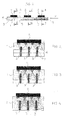
- a cooled base plate 1 for electric components according to the invention, a first side A (upper side in the drawings) of which base plate is provided for attaching thereto exothermal electric components 2, such as semiconductor modules and resistors, and on a second, opposite side B (lower side in the drawings) of which there is embedded a cooling channel system 3 having a cooling fluid inlet 4 at one end of the base plate and a cooling fluid outlet 5 at a second end of the base plate.
- the thickness of the base plate 1 mainly increases in the direction from the inlet 4 of the cooling channel system 3 towards the outlet 5 of the cooling channel system 5, i.e. in the flow direction F of the cooling fluid for at least a portion of the length of the base plate 1. In other words, this may also be expressed such that the thickness of the base plate 1 is reduced at the beginning of the cooling fluid flow.
- the thickness of the base plate 1 increases stepwise, preferably in the region of every exothermal electric component 2 or electric component array that is next in the flow direction F of the cooling fluid.
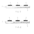
- the thickness of the base plate 1 increases at first continuously for a portion of the length of the base plate 1, the rest of the base plate 1 being uniform in thickness in the region of the last electric component 2 or electric component array.
- the thickness of the base plate 1 may increase as successive, protruding, for instance convex, wavy areas in the region of every exothermal electric component or electric component array that is next in the flow direction of the cooling fluid.
- the cooling channel system 3 associated with the base plate 1 consists of separate, finned pipes that are embedded in grooves 6 machined in the base plate 1 at a substantially even distance from a surface A provided for the attachment of electric components, whereby the base plate's heat transfer surface consisting of the grooves in the base plate 1 and associated with the finned rib pipes 3 increases in the flow direction F of the cooling fluid and whereby the protrusion of the finned pipes 3 from the base plate 1 reduces respectively in the flow direction of the cooling fluid.
- Each finned pipe 3 comprises here advantageously several superimposed flow channels 7.
- the electric component 2 which is on the side of the cooling fluid inlet 4 and receives liquid at its coldest and which is attached to the base plate 1 optimized in thickness in the above-described manner in accordance with the invention, encounters the smallest heat transfer area.
- This heat transfer area then appropriately increases as the cooling liquid gets warmer, when it propagates towards the outlet 5, and consequently the difference in temperature between the electric components 2 is minimized irrespective of their location on the base plate 1 in view of the cooling fluid flow.
- the shape of the base plate may be optimized such that the internal temperature differences of the electric component 2 are to be minimized. This is necessary in the case of current semiconductors, when the length of a module may be even more than 300mm. Examples of this include semiconductor chips in series, in connection with which temperature differences must be minimized, so that asymmetrical current distribution resulting from the temperature difference is minimized.
- An optimized base plate 1 of this kind may be, for instance, similar to the one shown in Figure 6 , whereby cooling area is largest at the centre of the electric component array 2.
- the cooling channel system may consist of any appropriate pipes and their cross-sectional shape is not restricted to the finned pipe structure, as the cross section of the pipe may be circular, for instance. It is also conceivable that the channel system is provided in the base plate itself.
Landscapes
- Engineering & Computer Science (AREA)
- Physics & Mathematics (AREA)
- Thermal Sciences (AREA)
- Microelectronics & Electronic Packaging (AREA)
- General Engineering & Computer Science (AREA)
- Mechanical Engineering (AREA)
- Life Sciences & Earth Sciences (AREA)
- Sustainable Development (AREA)
- Cooling Or The Like Of Semiconductors Or Solid State Devices (AREA)
- Cooling Or The Like Of Electrical Apparatus (AREA)
- Condensed Matter Physics & Semiconductors (AREA)
- General Physics & Mathematics (AREA)
- Computer Hardware Design (AREA)
- Power Engineering (AREA)
Applications Claiming Priority (1)
| Application Number | Priority Date | Filing Date | Title |
|---|---|---|---|
| FI20095959A FI122415B (fi) | 2009-09-17 | 2009-09-17 | Jäähdytettävä sähkökomponenttien pohjalevy |
Publications (3)
| Publication Number | Publication Date |
|---|---|
| EP2299489A2 true EP2299489A2 (de) | 2011-03-23 |
| EP2299489A3 EP2299489A3 (de) | 2012-11-07 |
| EP2299489B1 EP2299489B1 (de) | 2017-11-29 |
Family
ID=41136421
Family Applications (1)
| Application Number | Title | Priority Date | Filing Date |
|---|---|---|---|
| EP10176313.4A Active EP2299489B1 (de) | 2009-09-17 | 2010-09-13 | Gekühlte Grundplatte für elektrische Bauteile |
Country Status (4)
| Country | Link |
|---|---|
| US (1) | US8800640B2 (de) |
| EP (1) | EP2299489B1 (de) |
| CN (1) | CN102026525B (de) |
| FI (1) | FI122415B (de) |
Cited By (2)
| Publication number | Priority date | Publication date | Assignee | Title |
|---|---|---|---|---|
| EP2793261A1 (de) * | 2013-04-18 | 2014-10-22 | ABB Oy | Vorrichtung |
| EP3190371A1 (de) * | 2016-01-07 | 2017-07-12 | ABB Schweiz AG | Wärmetauscher für leistungselektronische komponenten |
Families Citing this family (3)
| Publication number | Priority date | Publication date | Assignee | Title |
|---|---|---|---|---|
| DE202012101076U1 (de) * | 2011-04-14 | 2012-04-19 | Visteon Global Technologies, Inc. | Vorrichtung zum Kühlen von Batterien, insbesondere für Kraftfahrzeuge |
| US11026347B2 (en) * | 2012-12-21 | 2021-06-01 | Smart Embedded Computing, Inc. | Configurable cooling for rugged environments |
| JP2022138488A (ja) * | 2021-03-10 | 2022-09-26 | パナソニックIpマネジメント株式会社 | 冷却装置 |
Family Cites Families (9)
| Publication number | Priority date | Publication date | Assignee | Title |
|---|---|---|---|---|
| US4953634A (en) * | 1989-04-20 | 1990-09-04 | Microelectronics And Computer Technology Corporation | Low pressure high heat transfer fluid heat exchanger |
| JPH0355874A (ja) * | 1989-07-25 | 1991-03-11 | Matsushita Electric Ind Co Ltd | 半導体装置 |
| JPH062314Y2 (ja) * | 1989-08-30 | 1994-01-19 | ナカミチ株式会社 | 放熱装置 |
| US6765793B2 (en) | 2002-08-30 | 2004-07-20 | Themis Corporation | Ruggedized electronics enclosure |
| EP1872079A2 (de) * | 2005-04-22 | 2008-01-02 | Ferrotec (USA) Corporation | Hochwirksamer fluidwärmetauscher und herstellungsverfahren |
| US7849914B2 (en) * | 2006-05-02 | 2010-12-14 | Clockspeed, Inc. | Cooling apparatus for microelectronic devices |
| US8757246B2 (en) * | 2006-06-06 | 2014-06-24 | Raytheon Company | Heat sink and method of making same |
| EP2031332B1 (de) * | 2007-08-27 | 2010-09-15 | ABB Research LTD | Wärmetauscher für Komponenten der Leistungselektronik |
| TWI423403B (zh) * | 2007-09-17 | 2014-01-11 | 萬國商業機器公司 | 積體電路疊層 |
-
2009
- 2009-09-17 FI FI20095959A patent/FI122415B/fi active IP Right Grant
-
2010
- 2010-09-13 EP EP10176313.4A patent/EP2299489B1/de active Active
- 2010-09-15 CN CN201010285632.9A patent/CN102026525B/zh active Active
- 2010-09-16 US US12/883,548 patent/US8800640B2/en active Active
Non-Patent Citations (1)
| Title |
|---|
| None |
Cited By (4)
| Publication number | Priority date | Publication date | Assignee | Title |
|---|---|---|---|---|
| EP2793261A1 (de) * | 2013-04-18 | 2014-10-22 | ABB Oy | Vorrichtung |
| US9392729B2 (en) | 2013-04-18 | 2016-07-12 | Abb Oy | Cooling apparatus |
| EP3190371A1 (de) * | 2016-01-07 | 2017-07-12 | ABB Schweiz AG | Wärmetauscher für leistungselektronische komponenten |
| US9888612B2 (en) | 2016-01-07 | 2018-02-06 | Abb Schweiz Ag | Heat exchanger for power-electronic components |
Also Published As
| Publication number | Publication date |
|---|---|
| US8800640B2 (en) | 2014-08-12 |
| CN102026525A (zh) | 2011-04-20 |
| EP2299489B1 (de) | 2017-11-29 |
| FI20095959A0 (fi) | 2009-09-17 |
| FI20095959L (fi) | 2011-03-18 |
| EP2299489A3 (de) | 2012-11-07 |
| FI122415B (fi) | 2012-01-13 |
| CN102026525B (zh) | 2014-03-05 |
| US20110061834A1 (en) | 2011-03-17 |
Similar Documents
| Publication | Publication Date | Title |
|---|---|---|
| CN102112841B (zh) | 用于机动车热源散热的装置 | |
| EP2299489B1 (de) | Gekühlte Grundplatte für elektrische Bauteile | |
| EP2681847B1 (de) | Kühlsystem und verfahren zur kühlung einer funkeinheit | |
| CN203859970U (zh) | 一种散热用双层冷却板及电子元件散热装置 | |
| US10892208B2 (en) | Heat dissipation apparatus and method for power semiconductor devices | |
| US20120080174A1 (en) | Heat exchangers for air conditioning systems | |
| EP2793261B1 (de) | Vorrichtung | |
| EP3144625B1 (de) | Kühlanordnung und verfahren zu deren herstellung | |
| CN107924897A (zh) | 层叠芯体型散热器 | |
| US10177425B2 (en) | Battery pack | |
| US20130175016A1 (en) | Heat exchanger | |
| WO2015113145A1 (en) | Radiator having a reverse flow manifold | |
| EP2383779A1 (de) | Montagebasis | |
| Lad et al. | Conventional and topologically optimized polymer manifolds for direct cooling of power electronics | |
| US10945354B1 (en) | Cooling systems comprising fluid diodes with variable diodicity for two-phase flow control | |
| US11656038B2 (en) | Heat exchanger with enhanced end sheet heat transfer | |
| CN104823279B (zh) | 功率晶闸管单元冷却系统 | |
| CN109696070B (zh) | 热交换器 | |
| KR101628042B1 (ko) | 정수기용 순간 냉각 유닛 | |
| EP2354744B1 (de) | Kühlelement | |
| CN112310014B (zh) | 冷却器主体 | |
| KR200232600Y1 (ko) | 열전소자를 이용한 열교환 장치 | |
| NL1035390C2 (nl) | Inrichting voor verwarming van ruimtes in een gebouw, een warmtewisselaar en een gebouw. | |
| US20240381567A1 (en) | Cooler for cooling power electronics | |
| KR102069514B1 (ko) | 조명장치 |
Legal Events
| Date | Code | Title | Description |
|---|---|---|---|
| PUAI | Public reference made under article 153(3) epc to a published international application that has entered the european phase |
Free format text: ORIGINAL CODE: 0009012 |
|
| AK | Designated contracting states |
Kind code of ref document: A2 Designated state(s): AL AT BE BG CH CY CZ DE DK EE ES FI FR GB GR HR HU IE IS IT LI LT LU LV MC MK MT NL NO PL PT RO SE SI SK SM TR |
|
| AX | Request for extension of the european patent |
Extension state: BA ME RS |
|
| PUAL | Search report despatched |
Free format text: ORIGINAL CODE: 0009013 |
|
| AK | Designated contracting states |
Kind code of ref document: A3 Designated state(s): AL AT BE BG CH CY CZ DE DK EE ES FI FR GB GR HR HU IE IS IT LI LT LU LV MC MK MT NL NO PL PT RO SE SI SK SM TR |
|
| AX | Request for extension of the european patent |
Extension state: BA ME RS |
|
| RIC1 | Information provided on ipc code assigned before grant |
Ipc: H01L 23/473 20060101AFI20121003BHEP Ipc: H01L 23/36 20060101ALI20121003BHEP |
|
| 17P | Request for examination filed |
Effective date: 20130404 |
|
| 17Q | First examination report despatched |
Effective date: 20140731 |
|
| GRAP | Despatch of communication of intention to grant a patent |
Free format text: ORIGINAL CODE: EPIDOSNIGR1 |
|
| RIC1 | Information provided on ipc code assigned before grant |
Ipc: H01L 23/36 20060101ALI20170320BHEP Ipc: F28D 15/02 20060101ALI20170320BHEP Ipc: H01L 23/473 20060101AFI20170320BHEP |
|
| INTG | Intention to grant announced |
Effective date: 20170412 |
|
| GRAS | Grant fee paid |
Free format text: ORIGINAL CODE: EPIDOSNIGR3 |
|
| RAP1 | Party data changed (applicant data changed or rights of an application transferred) |
Owner name: ABB TECHNOLOGY OY |
|
| GRAA | (expected) grant |
Free format text: ORIGINAL CODE: 0009210 |
|
| AK | Designated contracting states |
Kind code of ref document: B1 Designated state(s): AL AT BE BG CH CY CZ DE DK EE ES FI FR GB GR HR HU IE IS IT LI LT LU LV MC MK MT NL NO PL PT RO SE SI SK SM TR |
|
| REG | Reference to a national code |
Ref country code: CH Ref legal event code: EP |
|
| REG | Reference to a national code |
Ref country code: AT Ref legal event code: REF Ref document number: 951113 Country of ref document: AT Kind code of ref document: T Effective date: 20171215 |
|
| REG | Reference to a national code |
Ref country code: IE Ref legal event code: FG4D |
|
| REG | Reference to a national code |
Ref country code: DE Ref legal event code: R096 Ref document number: 602010046998 Country of ref document: DE |
|
| REG | Reference to a national code |
Ref country code: NL Ref legal event code: MP Effective date: 20171129 |
|
| REG | Reference to a national code |
Ref country code: LT Ref legal event code: MG4D |
|
| REG | Reference to a national code |
Ref country code: AT Ref legal event code: MK05 Ref document number: 951113 Country of ref document: AT Kind code of ref document: T Effective date: 20171129 |
|
| PG25 | Lapsed in a contracting state [announced via postgrant information from national office to epo] |
Ref country code: NO Free format text: LAPSE BECAUSE OF FAILURE TO SUBMIT A TRANSLATION OF THE DESCRIPTION OR TO PAY THE FEE WITHIN THE PRESCRIBED TIME-LIMIT Effective date: 20180228 Ref country code: ES Free format text: LAPSE BECAUSE OF FAILURE TO SUBMIT A TRANSLATION OF THE DESCRIPTION OR TO PAY THE FEE WITHIN THE PRESCRIBED TIME-LIMIT Effective date: 20171129 Ref country code: SE Free format text: LAPSE BECAUSE OF FAILURE TO SUBMIT A TRANSLATION OF THE DESCRIPTION OR TO PAY THE FEE WITHIN THE PRESCRIBED TIME-LIMIT Effective date: 20171129 Ref country code: LT Free format text: LAPSE BECAUSE OF FAILURE TO SUBMIT A TRANSLATION OF THE DESCRIPTION OR TO PAY THE FEE WITHIN THE PRESCRIBED TIME-LIMIT Effective date: 20171129 Ref country code: FI Free format text: LAPSE BECAUSE OF FAILURE TO SUBMIT A TRANSLATION OF THE DESCRIPTION OR TO PAY THE FEE WITHIN THE PRESCRIBED TIME-LIMIT Effective date: 20171129 |
|
| PG25 | Lapsed in a contracting state [announced via postgrant information from national office to epo] |
Ref country code: LV Free format text: LAPSE BECAUSE OF FAILURE TO SUBMIT A TRANSLATION OF THE DESCRIPTION OR TO PAY THE FEE WITHIN THE PRESCRIBED TIME-LIMIT Effective date: 20171129 Ref country code: HR Free format text: LAPSE BECAUSE OF FAILURE TO SUBMIT A TRANSLATION OF THE DESCRIPTION OR TO PAY THE FEE WITHIN THE PRESCRIBED TIME-LIMIT Effective date: 20171129 Ref country code: GR Free format text: LAPSE BECAUSE OF FAILURE TO SUBMIT A TRANSLATION OF THE DESCRIPTION OR TO PAY THE FEE WITHIN THE PRESCRIBED TIME-LIMIT Effective date: 20180301 Ref country code: AT Free format text: LAPSE BECAUSE OF FAILURE TO SUBMIT A TRANSLATION OF THE DESCRIPTION OR TO PAY THE FEE WITHIN THE PRESCRIBED TIME-LIMIT Effective date: 20171129 Ref country code: BG Free format text: LAPSE BECAUSE OF FAILURE TO SUBMIT A TRANSLATION OF THE DESCRIPTION OR TO PAY THE FEE WITHIN THE PRESCRIBED TIME-LIMIT Effective date: 20180228 |
|
| PG25 | Lapsed in a contracting state [announced via postgrant information from national office to epo] |
Ref country code: NL Free format text: LAPSE BECAUSE OF FAILURE TO SUBMIT A TRANSLATION OF THE DESCRIPTION OR TO PAY THE FEE WITHIN THE PRESCRIBED TIME-LIMIT Effective date: 20171129 |
|
| PG25 | Lapsed in a contracting state [announced via postgrant information from national office to epo] |
Ref country code: SK Free format text: LAPSE BECAUSE OF FAILURE TO SUBMIT A TRANSLATION OF THE DESCRIPTION OR TO PAY THE FEE WITHIN THE PRESCRIBED TIME-LIMIT Effective date: 20171129 Ref country code: CZ Free format text: LAPSE BECAUSE OF FAILURE TO SUBMIT A TRANSLATION OF THE DESCRIPTION OR TO PAY THE FEE WITHIN THE PRESCRIBED TIME-LIMIT Effective date: 20171129 Ref country code: CY Free format text: LAPSE BECAUSE OF FAILURE TO SUBMIT A TRANSLATION OF THE DESCRIPTION OR TO PAY THE FEE WITHIN THE PRESCRIBED TIME-LIMIT Effective date: 20171129 Ref country code: EE Free format text: LAPSE BECAUSE OF FAILURE TO SUBMIT A TRANSLATION OF THE DESCRIPTION OR TO PAY THE FEE WITHIN THE PRESCRIBED TIME-LIMIT Effective date: 20171129 Ref country code: DK Free format text: LAPSE BECAUSE OF FAILURE TO SUBMIT A TRANSLATION OF THE DESCRIPTION OR TO PAY THE FEE WITHIN THE PRESCRIBED TIME-LIMIT Effective date: 20171129 |
|
| REG | Reference to a national code |
Ref country code: DE Ref legal event code: R097 Ref document number: 602010046998 Country of ref document: DE |
|
| PG25 | Lapsed in a contracting state [announced via postgrant information from national office to epo] |
Ref country code: RO Free format text: LAPSE BECAUSE OF FAILURE TO SUBMIT A TRANSLATION OF THE DESCRIPTION OR TO PAY THE FEE WITHIN THE PRESCRIBED TIME-LIMIT Effective date: 20171129 Ref country code: SM Free format text: LAPSE BECAUSE OF FAILURE TO SUBMIT A TRANSLATION OF THE DESCRIPTION OR TO PAY THE FEE WITHIN THE PRESCRIBED TIME-LIMIT Effective date: 20171129 Ref country code: PL Free format text: LAPSE BECAUSE OF FAILURE TO SUBMIT A TRANSLATION OF THE DESCRIPTION OR TO PAY THE FEE WITHIN THE PRESCRIBED TIME-LIMIT Effective date: 20171129 |
|
| REG | Reference to a national code |
Ref country code: DE Ref legal event code: R081 Ref document number: 602010046998 Country of ref document: DE Owner name: ABB SCHWEIZ AG, CH Free format text: FORMER OWNER: ABB TECHNOLOGY OY, HELSINKI, FI |
|
| REG | Reference to a national code |
Ref country code: FR Ref legal event code: PLFP Year of fee payment: 9 |
|
| PLBE | No opposition filed within time limit |
Free format text: ORIGINAL CODE: 0009261 |
|
| STAA | Information on the status of an ep patent application or granted ep patent |
Free format text: STATUS: NO OPPOSITION FILED WITHIN TIME LIMIT |
|
| 26N | No opposition filed |
Effective date: 20180830 |
|
| PG25 | Lapsed in a contracting state [announced via postgrant information from national office to epo] |
Ref country code: SI Free format text: LAPSE BECAUSE OF FAILURE TO SUBMIT A TRANSLATION OF THE DESCRIPTION OR TO PAY THE FEE WITHIN THE PRESCRIBED TIME-LIMIT Effective date: 20171129 |
|
| PG25 | Lapsed in a contracting state [announced via postgrant information from national office to epo] |
Ref country code: MC Free format text: LAPSE BECAUSE OF FAILURE TO SUBMIT A TRANSLATION OF THE DESCRIPTION OR TO PAY THE FEE WITHIN THE PRESCRIBED TIME-LIMIT Effective date: 20171129 |
|
| REG | Reference to a national code |
Ref country code: CH Ref legal event code: PL |
|
| GBPC | Gb: european patent ceased through non-payment of renewal fee |
Effective date: 20180913 |
|
| REG | Reference to a national code |
Ref country code: BE Ref legal event code: MM Effective date: 20180930 |
|
| REG | Reference to a national code |
Ref country code: IE Ref legal event code: MM4A |
|
| PG25 | Lapsed in a contracting state [announced via postgrant information from national office to epo] |
Ref country code: LU Free format text: LAPSE BECAUSE OF NON-PAYMENT OF DUE FEES Effective date: 20180913 |
|
| PG25 | Lapsed in a contracting state [announced via postgrant information from national office to epo] |
Ref country code: IE Free format text: LAPSE BECAUSE OF NON-PAYMENT OF DUE FEES Effective date: 20180913 |
|
| PG25 | Lapsed in a contracting state [announced via postgrant information from national office to epo] |
Ref country code: LI Free format text: LAPSE BECAUSE OF NON-PAYMENT OF DUE FEES Effective date: 20180930 Ref country code: CH Free format text: LAPSE BECAUSE OF NON-PAYMENT OF DUE FEES Effective date: 20180930 Ref country code: BE Free format text: LAPSE BECAUSE OF NON-PAYMENT OF DUE FEES Effective date: 20180930 |
|
| PG25 | Lapsed in a contracting state [announced via postgrant information from national office to epo] |
Ref country code: GB Free format text: LAPSE BECAUSE OF NON-PAYMENT OF DUE FEES Effective date: 20180913 |
|
| PG25 | Lapsed in a contracting state [announced via postgrant information from national office to epo] |
Ref country code: MT Free format text: LAPSE BECAUSE OF NON-PAYMENT OF DUE FEES Effective date: 20180913 |
|
| PG25 | Lapsed in a contracting state [announced via postgrant information from national office to epo] |
Ref country code: TR Free format text: LAPSE BECAUSE OF FAILURE TO SUBMIT A TRANSLATION OF THE DESCRIPTION OR TO PAY THE FEE WITHIN THE PRESCRIBED TIME-LIMIT Effective date: 20171129 |
|
| PG25 | Lapsed in a contracting state [announced via postgrant information from national office to epo] |
Ref country code: PT Free format text: LAPSE BECAUSE OF FAILURE TO SUBMIT A TRANSLATION OF THE DESCRIPTION OR TO PAY THE FEE WITHIN THE PRESCRIBED TIME-LIMIT Effective date: 20171129 Ref country code: HU Free format text: LAPSE BECAUSE OF FAILURE TO SUBMIT A TRANSLATION OF THE DESCRIPTION OR TO PAY THE FEE WITHIN THE PRESCRIBED TIME-LIMIT; INVALID AB INITIO Effective date: 20100913 |
|
| PG25 | Lapsed in a contracting state [announced via postgrant information from national office to epo] |
Ref country code: MK Free format text: LAPSE BECAUSE OF NON-PAYMENT OF DUE FEES Effective date: 20171129 |
|
| PG25 | Lapsed in a contracting state [announced via postgrant information from national office to epo] |
Ref country code: AL Free format text: LAPSE BECAUSE OF FAILURE TO SUBMIT A TRANSLATION OF THE DESCRIPTION OR TO PAY THE FEE WITHIN THE PRESCRIBED TIME-LIMIT Effective date: 20171129 Ref country code: IS Free format text: LAPSE BECAUSE OF FAILURE TO SUBMIT A TRANSLATION OF THE DESCRIPTION OR TO PAY THE FEE WITHIN THE PRESCRIBED TIME-LIMIT Effective date: 20180329 |
|
| PGFP | Annual fee paid to national office [announced via postgrant information from national office to epo] |
Ref country code: DE Payment date: 20250919 Year of fee payment: 16 |
|
| PGFP | Annual fee paid to national office [announced via postgrant information from national office to epo] |
Ref country code: IT Payment date: 20250923 Year of fee payment: 16 |
|
| PGFP | Annual fee paid to national office [announced via postgrant information from national office to epo] |
Ref country code: FR Payment date: 20250919 Year of fee payment: 16 |
|
| REG | Reference to a national code |
Ref country code: DE Ref legal event code: R079 Ref document number: 602010046998 Country of ref document: DE Free format text: PREVIOUS MAIN CLASS: H01L0023473000 Ipc: H10W0040470000 |