EP2299391A2 - Integrierte Schaltung und elektronische Vorrichtung - Google Patents
Integrierte Schaltung und elektronische Vorrichtung Download PDFInfo
- Publication number
- EP2299391A2 EP2299391A2 EP10174215A EP10174215A EP2299391A2 EP 2299391 A2 EP2299391 A2 EP 2299391A2 EP 10174215 A EP10174215 A EP 10174215A EP 10174215 A EP10174215 A EP 10174215A EP 2299391 A2 EP2299391 A2 EP 2299391A2
- Authority
- EP
- European Patent Office
- Prior art keywords
- power
- circuit
- voltage
- supply
- supply line
- Prior art date
- Legal status (The legal status is an assumption and is not a legal conclusion. Google has not performed a legal analysis and makes no representation as to the accuracy of the status listed.)
- Granted
Links
Images


Classifications
-
- G—PHYSICS
- G06—COMPUTING OR CALCULATING; COUNTING
- G06K—GRAPHICAL DATA READING; PRESENTATION OF DATA; RECORD CARRIERS; HANDLING RECORD CARRIERS
- G06K19/00—Record carriers for use with machines and with at least a part designed to carry digital markings
- G06K19/06—Record carriers for use with machines and with at least a part designed to carry digital markings characterised by the kind of the digital marking, e.g. shape, nature, code
- G06K19/067—Record carriers with conductive marks, printed circuits or semiconductor circuit elements, e.g. credit or identity cards also with resonating or responding marks without active components
- G06K19/07—Record carriers with conductive marks, printed circuits or semiconductor circuit elements, e.g. credit or identity cards also with resonating or responding marks without active components with integrated circuit chips
- G06K19/0723—Record carriers with conductive marks, printed circuits or semiconductor circuit elements, e.g. credit or identity cards also with resonating or responding marks without active components with integrated circuit chips the record carrier comprising an arrangement for non-contact communication, e.g. wireless communication circuits on transponder cards, non-contact smart cards or RFIDs
-
- G—PHYSICS
- G06—COMPUTING OR CALCULATING; COUNTING
- G06F—ELECTRIC DIGITAL DATA PROCESSING
- G06F21/00—Security arrangements for protecting computers, components thereof, programs or data against unauthorised activity
- G06F21/70—Protecting specific internal or peripheral components, in which the protection of a component leads to protection of the entire computer
- G06F21/71—Protecting specific internal or peripheral components, in which the protection of a component leads to protection of the entire computer to assure secure computing or processing of information
- G06F21/75—Protecting specific internal or peripheral components, in which the protection of a component leads to protection of the entire computer to assure secure computing or processing of information by inhibiting the analysis of circuitry or operation
- G06F21/755—Protecting specific internal or peripheral components, in which the protection of a component leads to protection of the entire computer to assure secure computing or processing of information by inhibiting the analysis of circuitry or operation with measures against power attack
-
- G—PHYSICS
- G06—COMPUTING OR CALCULATING; COUNTING
- G06K—GRAPHICAL DATA READING; PRESENTATION OF DATA; RECORD CARRIERS; HANDLING RECORD CARRIERS
- G06K19/00—Record carriers for use with machines and with at least a part designed to carry digital markings
- G06K19/06—Record carriers for use with machines and with at least a part designed to carry digital markings characterised by the kind of the digital marking, e.g. shape, nature, code
- G06K19/067—Record carriers with conductive marks, printed circuits or semiconductor circuit elements, e.g. credit or identity cards also with resonating or responding marks without active components
- G06K19/07—Record carriers with conductive marks, printed circuits or semiconductor circuit elements, e.g. credit or identity cards also with resonating or responding marks without active components with integrated circuit chips
- G06K19/073—Special arrangements for circuits, e.g. for protecting identification code in memory
- G06K19/07309—Means for preventing undesired reading or writing from or onto record carriers
- G06K19/07363—Means for preventing undesired reading or writing from or onto record carriers by preventing analysis of the circuit, e.g. dynamic or static power analysis or current analysis
-
- G—PHYSICS
- G06—COMPUTING OR CALCULATING; COUNTING
- G06K—GRAPHICAL DATA READING; PRESENTATION OF DATA; RECORD CARRIERS; HANDLING RECORD CARRIERS
- G06K19/00—Record carriers for use with machines and with at least a part designed to carry digital markings
- G06K19/06—Record carriers for use with machines and with at least a part designed to carry digital markings characterised by the kind of the digital marking, e.g. shape, nature, code
- G06K19/067—Record carriers with conductive marks, printed circuits or semiconductor circuit elements, e.g. credit or identity cards also with resonating or responding marks without active components
- G06K19/07—Record carriers with conductive marks, printed circuits or semiconductor circuit elements, e.g. credit or identity cards also with resonating or responding marks without active components with integrated circuit chips
- G06K19/077—Constructional details, e.g. mounting of circuits in the carrier
- G06K19/07749—Constructional details, e.g. mounting of circuits in the carrier the record carrier being capable of non-contact communication, e.g. constructional details of the antenna of a non-contact smart card
- G06K19/07771—Constructional details, e.g. mounting of circuits in the carrier the record carrier being capable of non-contact communication, e.g. constructional details of the antenna of a non-contact smart card the record carrier comprising means for minimising adverse effects on the data communication capability of the record carrier, e.g. minimising Eddy currents induced in a proximate metal or otherwise electromagnetically interfering object
-
- G—PHYSICS
- G06—COMPUTING OR CALCULATING; COUNTING
- G06K—GRAPHICAL DATA READING; PRESENTATION OF DATA; RECORD CARRIERS; HANDLING RECORD CARRIERS
- G06K19/00—Record carriers for use with machines and with at least a part designed to carry digital markings
- G06K19/06—Record carriers for use with machines and with at least a part designed to carry digital markings characterised by the kind of the digital marking, e.g. shape, nature, code
- G06K19/067—Record carriers with conductive marks, printed circuits or semiconductor circuit elements, e.g. credit or identity cards also with resonating or responding marks without active components
- G06K19/07—Record carriers with conductive marks, printed circuits or semiconductor circuit elements, e.g. credit or identity cards also with resonating or responding marks without active components with integrated circuit chips
- G06K19/077—Constructional details, e.g. mounting of circuits in the carrier
- G06K19/07749—Constructional details, e.g. mounting of circuits in the carrier the record carrier being capable of non-contact communication, e.g. constructional details of the antenna of a non-contact smart card
- G06K19/07773—Antenna details
- G06K19/07775—Antenna details the antenna being on-chip
Definitions
- the present invention relates to an integrated circuit in which an encryption circuit is incorporated, and an electronic apparatus.
- IC cards when sending/receiving of data is performed between the IC cards and host computers, in order to prevent problems from occurring even in a case in which confidential information stored in the IC cards leaks in the course of sending/receiving data, encrypted data is used as data to be send/received.
- a method that is most frequently used at present as a method for encrypting such data is the data encryption standard (DES).
- DES data encryption standard
- DES for encryption of data
- the owner of such an IC card and a host computer have the same key.
- a sending side for data encrypts the data using the key, and sends the encrypted data.
- a receiving side for the data decrypts the data using the same key, and extracts a message.
- a non-volatile memory such as an electrically erasable programmable read-only memory (EEPROM), that is provided in the IC card.
- EEPROM electrically erasable programmable read-only memory
- control of directly transferring the data concerning the key to an encryption engine that is provided in the IC card without using a central processing unit (CPU) is performed.
- CPU central processing unit
- IC cards Two types of IC cards, i.e., a contact IC card and a non-contact IC card, exist.
- the contact IC card has a plurality of metallic terminals on the surface thereof.
- the IC card is inserted into a reader/writer apparatus.
- the metallic terminals are in contact with the reader/writer apparatus.
- the read/writer apparatus supplies power and signals to the IC card, thereby causing an IC which is provided in the IC card to operate so that a necessary process is performed.
- a configuration illustrated in Fig. 1 is employed.
- An antenna 11 that is disposed in a non-contact IC card 1 receives magnetic lines of force LM from a reader/writer apparatus 2, and converts the magnetic lines of force LM into a signal indicating electromotive force.
- the signal is input to a radio frequency (RF) chip 12, and the RF chip 12 extracts a necessary signal.
- RF radio frequency
- a constant voltage is generated from the electromotive force that is generated in the antenna 11.
- the constant voltage is supplied to a secure application module (SAM) chip 13 that performs a process associated security, and the SAM chip 13 performs a necessary process.
- SAM secure application module
- a result of the process performed by the SAM chip 13 is sent back to the RF chip 12.
- the result is superimposed on a signal waveform, and is sent back to the reader/writer 2.
- encrypted data is used as a sent/received signal. This ensures security of a system.
- encryption arithmetic is performed using about 1,000 different clear texts.
- a consumed current at the time of encryption arithmetic is measured to obtain a waveform thereof.
- a key is extracted by performing a statistical process on the consumed current.
- the DPA attack can also be performed on a non-contact IC card. Only the SAM chip that performs a process associated with security is demounted. By supplying power and necessary signals, the SAM chip is caused to operate. Accordingly, the DPA attack can be performed.
- the position of an encryption circuit is estimated using the relationships between signals that are input/output to/from the IC chip and the obtained signal indicating magnetic lines of force.
- a waveform of a more specific signal indicating the magnetic lines of force is obtained at the position, and a statistical process which is similar to that performed in the DPA attack is performed. If estimation of the position of the encryption circuit is correctly performed, security information, such as information concerning a key, can be obtained.
- the above attack is called a differential electro magnetic analysis (DEMA) attack.
- DEMA differential electro magnetic analysis
- an attack that targets one portion of a circuit can be performed using the DEMA attack.
- Fig. 3 is a diagram illustrating a feature of the DEMA attack.
- the strength of an element of a magnetic field indicated by magnetic lines of force caused by the noise current decreases with a distance from a noise-current source as illustrated in Fig. 3 .
- a signal indicating magnetic lines of force that are not influenced by the noise current can be obtained in a region that is a predetermined distance or more far from the noise-current source.
- a first method is a method in which an encryption circuit has a complementary configuration, thereby employing a configuration in which a result assuredly changes regardless of clear text data.
- a second method is a method in which signals are disturbed using random numbers.
- a method disclosed in Japanese Unexamined Patent Application Publication No. 2000-196584 is common as a method in which a current flowing through a particular circuit such as an encryption circuit does not appear at a power-supply terminal of an IC.
- Fig. 4 is a diagram illustrating an example of a configuration of an IC in which the method disclosed in Japanese Unexamined Patent Application Publication No. 2000-196584 is employed.
- An IC 4 includes a CPU 41, a random-access memory (RAM)/read-only memory (ROM) 42, an EEPROM 43, an encryption circuit 44, a capacitor C, and a switch 45.
- RAM random-access memory
- ROM read-only memory
- a power-supply line 46 for the encryption circuit 44 that is provided in the IC 4 is connected via the switch 45 to another power-supply line 47 to which an external power supply is connected.
- the capacitor C is disposed between the power-supply line 46 associated with encryption and a ground (GND) line 48.
- the switch 45 is turned on, and the capacitor C is charged. Then, at a time of encryption arithmetic, the switch 45 is turned off, and the encryption arithmetic is performed in the encryption circuit 44 using charge in the charged capacitor C.
- An integrated circuit includes the following elements: a semiconductor-circuit layer; metal layers formed on the semiconductor-circuit layer, one of the metal layers being a metal layer in which an active shield is formed; and an antenna formed by patterning in at least one of the metal layers that are below the metal layer in which the active shield is formed.
- the semiconductor-circuit layer includes the following elements: an encryption circuit configured to receive a drive voltage and to perform encryption arithmetic; a power-supply circuit configured to provide the drive voltage to the encryption circuit; and a circuit system configured to receive a power-supply voltage from an external power supply.
- An electronic apparatus includes an integrated circuit having an encryption circuit.
- the integrated circuit includes the following elements: a semiconductor-circuit layer; metal layers formed on the semiconductor-circuit layer, one of the metal layers being a metal layer in which an active shield is formed; and an antenna formed by patterning in at least one of the metal layers that are below the metal layer in which the active shield is formed.
- the semiconductor-circuit layer includes the following elements: an encryption circuit configured to receive a drive voltage and to perform encryption arithmetic; a power-supply circuit configured to provide the drive voltage to the encryption circuit; and a circuit system configured to receive a power-supply voltage from an external power supply.
- resistance to the DPA attack can be realized because a large capacitor is not necessary and because an operating current of the encryption circuit does not appear on a power-supply line of the integrated circuit, and resistance to the DEMA attack can be realized because it is difficult to measure a magnetic field associated with a circuit operation.
- Parts (A) to (C) of Fig. 5 are diagrams illustrating an example of a security semiconductor LSI, which has an encryption processing circuit, according to a first embodiment of the present invention.
- a security LSI 100 is formed as a non-conduct IC card that is an electronic device.
- the security LSI 100 is formed using a semiconductor layer (a silicon (Si) layer) and five metal layers which are formed on the semiconductor layer and in which metal wiring patterns are formed, thereby configuring an IC chip in which a semiconductor circuit is formed.
- a semiconductor layer a silicon (Si) layer
- metal layers which are formed on the semiconductor layer and in which metal wiring patterns are formed, thereby configuring an IC chip in which a semiconductor circuit is formed.
- a configuration and function is assigned to each of the metal layers, for example, as described below.
- the configuration and function of a layer in which signal lines in the horizontal direction are formed is assigned to a first metal layer (1MT) 102 formed on an Si layer 101.
- the configuration and function of a layer in which signal lines in the vertical direction are formed is assigned to a second metal layer (2MT) 103 formed on the first metal layer 102.
- the configuration and function of a layer in which power-supply lines and dummy metal patterns are formed is assigned to a third metal layer (3MT) 104 formed on the second metal layer 103.
- the configuration and function of a layer in which lines connected to the ground and dummy metal patterns are formed is assigned to a fourth metal layer (4MT) 105 formed on the third metal layer 104.
- the configuration and function of a layer in which an active shield is formed is assigned to a fifth metal layer (5MT) 106 formed on the fourth metal layer 105.
- 5MT fifth metal layer
- the active shield formed in the fifth metal layer 106 that is the top layer among the five metal layers is formed as a pattern in which signal lines having the minimum line width are disposed at the minimum intervals. With the active shield, disconnection or short of a signal line that is caused by a process using a focused ion beam (FIB) or the like.
- FIB focused ion beam
- Lines connected to the ground (reference-power-supply lines and ground lines) and power-supply lines are disposed in the fourth metal layer 105 and the third metal layer 104, respectively. Additionally, dummy metal patterns are disposed in empty spaces.
- the dummy metal patterns are light-shielding patterns for dealing with the DPA attack using radiation of a laser beam.
- a predetermined region is reserved in the fourth metal layer 105, and a metal antenna pattern 110 (hereinafter, referred to as a "metal antenna 110") is disposed.
- a power-supply circuit 120, an encryption circuit 130, and a processing circuit 140 that serves as a circuit system are formed.
- the power-supply circuit 120 includes a rectifying circuit 121 configured using a diode bridge, a smoothing circuit 122 configured using a capacitor C121, a constant-voltage-generating circuit 123 configured using a n-channel metal-oxide-semiconductor (NMOS) transistor NT121, and a capacitor C122 for stabilizing a voltage that is output from the constant-voltage-generating circuit 123.
- a stabilization unit 124 that stabilizes the voltage is configured using the capacitor C122.
- a first input terminal TI121 and a second input terminal TI122 of the rectifying circuit 121 are connected to the metal antenna 110 formed in the fourth metal layer 105.
- the power-supply circuit 120 has a first power-supply line LV121 and a first GND line (reference-power-supply line) LV122 that are different from a power-supply line and a ground line for the processing circuit 140.
- One of two ends of the first power-supply line LV121 is connected to a first output terminal TO121 of the rectifying circuit 121 via the NMOS transistor NT121.
- One of two ends of the first GND line LV122 is connected to a second output terminal TO122 of the rectifying circuit 121.
- the other end of the first power-supply line LV121 is connected to a power-supply terminal T131 of the encryption circuit 130.
- the other end of the first GND line LV122 is connected to a GND terminal T132 of the encryption circuit 130.
- an output of the power-supply circuit 120 is connected only to the power-supply terminal of the encryption circuit 130.
- the encryption circuit 130 receives provision of a drive voltage only from the power-supply circuit 120.
- electromotive force indicated by magnetic lines of force which are received by the metal antenna 110 is converted into a constant voltage.
- the constant voltage is used as a voltage of a power supply with which the encryption circuit 130 operates.
- the processing circuit 140 includes a CPU 141 that serves as a control unit which performs overall control of the processing circuit 140, a mask ROM 142, an RAM 143, and a non-volatile memory (EEPROM) 144.
- a CPU 141 that serves as a control unit which performs overall control of the processing circuit 140
- a mask ROM 142 that serves as a control unit which performs overall control of the processing circuit 140
- an RAM 143 As illustrated in part (C) of Fig. 5 , the processing circuit 140 includes a CPU 141 that serves as a control unit which performs overall control of the processing circuit 140, a mask ROM 142, an RAM 143, and a non-volatile memory (EEPROM) 144.
- EEPROM non-volatile memory
- a circuit system is configured using the CPU 141, the mask ROM 142, the RAM 143, and so forth.
- the processing circuit 140 in the first embodiment has a second power-supply line LV141 and a second GND line LV142 which are different from the power-supply line and the ground line of the power-supply circuit 120 and through which an external-power-supply voltage "V cc " is provided from an external power supply.
- the CPU 141 performs overall control of the security LSI 100 that is a non-contact IC card, in accordance with a program stored in the mask ROM 142 or by accessing the RAM 143.
- the CPU 41 has a function of issuing an encryption command to the encryption circuit 130 and so forth.
- the metal antenna 110 is disposed only in the fourth metal layer 105 that is used as a layer in which GND wiring patterns are formed.
- a metal antenna can also be disposed in a region of the third metal layer 104 that is used as a layer in which power-supply wiring patterns are formed.
- the metal antenna 110 in the fourth metal layer 105 and the metal antenna in the third metal layer 104 can be connected to each other, and the two metal antennas can also be used as one antenna.
- a high voltage that is equal to or higher than the external-power-supply voltage V cc is applied to a path from the rectifying circuit 121 to the constant-voltage-generating circuit 123. Accordingly, high-voltage transistors are necessary.
- the high voltage is periodically applied to the path at a frequency at which magnetic lines of force change. Accordingly, in order to prevent malfunction of the CPU 141 and the other circuits, which are disposed on the same chip, that is caused by a signal having the high voltage, it is preferable that components along the path be disposed in a region having a well separated from a well for the CPU 141 and the other circuits so that the components are electrically separated from the CPU 141 and the other circuits.
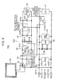
- Fig. 6 is a diagram illustrating a configuration of a more specific circuit for generating a constant voltage in the security LSI 100 according to the first embodiment.
- Parts (A) to (D) of Fig. 7 are timing diagrams for explaining an operation of the circuit illustrated in Fig. 6 .
- a comparator 125 In the circuit illustrated in Fig. 6 , a comparator 125, resistors R121 and R122, resistors R141 and R142, an NMOS transistor NT151, and a p-channel metal-oxide-semiconductor (PMOS) transistor PT151 are provided in addition to the components included in the configuration illustrated in part (C) of Fig. 5 .
- PMOS metal-oxide-semiconductor
- the resistors R121 and R122 are connected in series between the first power-supply line LV121 and the first GND line LV122 of the power-supply circuit 120.
- a connection node ND121 that is common to both the resistors R121 and R122 is connected to an inverting input terminal (-) of the comparator 125.
- the resistors R141 and R142 are connected in series between the second power-supply line LV141 and the second GND line LV142 of the processing circuit 140.
- a connection node ND141 that is common to both the resistors R141 and R142 is connected to a non-inverting input terminal (+) of the comparator 125.
- the second output terminal TO122 of the rectifying circuit 121 of the power-supply circuit 120 and the second GND line LV142, which is connected to the external power supply, of the processing circuit 140 are connected to the source and drain of the NMOS transistor NT151, respectively.
- the gate (control terminal) of the NMOS transistor NT151 is connected to the second power-supply line LV141 that is a line through which the external-power-supply voltage V cc is provided.
- GND levels of the power-supply circuit 120 and the processing circuit 140 which are two blocks are controlled so that the GND levels will be the same level.
- the NMOS transistor NT121 with which the constant-voltage-generating circuit 123 is configured, is disposed on the first power-supply line LV121.
- the output of the comparator 125 is connected to the gate (control terminal) of the NMOS transistor NT121.
- the comparator 125 compares a voltage that is obtained by dividing the external-power-supply voltage V cc using the resistors R141 and R142 with a voltage that is obtained by dividing a voltage "V DES ", which is output from the constant-voltage-generating circuit 123, using the resistors R121 and R122. In accordance with a result of comparison, the comparator 125 controls whether the NMOS transistor NT121 is turned on or off, thereby controlling the voltage output from the constant-voltage-generating circuit 123 so that the voltage will be a predetermined voltage.
- the first power-supply line LV121 through which the voltage "V DFS " that is output from the constant-voltage-generating circuit 123 and that is a voltage across the stabilization unit 124 is provided, and the second power-supply line LV141, through which the external-power-supply voltage V CC is provided, are connected to the source and drain of the PMOS transistor PT151, respectively.
- the gate of the PMOS transistor PT151 is connected to a line through which a control signal "TST" is supplied.
- a configuration is employed, in which the external-power-supply voltage V cc is provided to the encryption circuit 130 by setting the level of the control signal " TST " to be low at least in the state in which the IC chips are formed on a wafer.
- the power-supply circuit 120 no power is supplied to the path, which includes the comparator 125, from the rectifying circuit 121 to the constant-voltage-generating circuit 123. Accordingly, the level of a signal "V o " that is output from the comparator 125 is set to be low, thereby turning off the NMOS transistor NT121. Thus, provision of the external-power-supply voltage to the constant-voltage-generating circuit in the reverse direction does not occur.
- a built-in fuse may be used instead of the PMOS transistor PT151, and a configuration in which the In-fuse is cut in a certain process before shipment may be employed.
- the electromotive force generated in the metal antenna 110 when a magnetic flex of magnetic lines of force is denoted by ⁇ B [Wb] and the number of turns in an antenna coil is denoted by N [turns], the electromotive force ⁇ [V] is represented by the following equation in accordance with the law of electromagnetic induction.
- a voltage signal indicating the electromotive force has a waveform illustrated in part (A) of Fig. 7 .
- ⁇ - N ⁇ d ⁇ B dt
- the voltage signal When the voltage signal has passed the rectifying circuit 121, the voltage signal has a waveform illustrated in part (B) of Fig. 7 . Then, using the smoothing capacitor C121 of the smoothing circuit 122, the voltage signal has a waveform illustrated in part (C) of Fig. 7 . The voltage signal is applied to the drain of the NMOS transistor NT121.
- V ref R ⁇ 2 R ⁇ 1 + R ⁇ 2 ⁇ V cc
- R1 and R2 denote a resistor value of the resistor R141 and a resistor value of the resistor R142, respectively.
- V mon R ⁇ 4 R ⁇ 3 + R ⁇ 4 ⁇ V DES
- R3 and R4 denote a resistor value of the resistor R121 and a resistor value of the resistor R122, respectively.
- V DES > V cc the level of the signal V o output from the comparator 125 is low. Accordingly, the NMOS transistor NT121 is turned off, and control of stopping supply of charge is performed.
- control is performed so that the voltage V DES which is provided to the power-supply terminal of the encryption circuit 130 will coincide with the external-power-supply voltage V cc , thereby obtaining a waveform illustrated in part (D) of Fig. 7 .
- the CPU 141 and the encryption circuit 130 operate using power supplies that supply substantially the same voltage value, and can directly be connected to each other without providing a level shift circuit or the like therebetween.
- the encryption circuit 130 when data necessary for arithmetic and an arithmetic start command are issued by the CPU 141, the encryption circuit 130 operates using the voltage "V DES " that is generated from the electromotive force generated in the metal antenna 110.
- the voltage V DES is separated from the external-power-supply voltage V cc .
- a leakage current caused by encryption arithmetic does not appear on the second power-supply line LV141 for the external-power-supply voltage V cc . It is difficult to obtain a waveform of a consumed current including the leakage current.
- Fig. 9 is a diagram illustrating a configuration of a more specific circuit for generating a constant voltage in a security LSI according to a second embodiment.
- a configuration is used, in which the power supply for supplying power to the encryption circuit 130 can be switched using a switch SW121 between the power supply (a terminal a side) that provides a voltage which is generated as a constant voltage from the electromotive force generated in the metal antenna 110 and the external power supply (a terminal b side).
- an external input clock signal CLK and a voltage V Di generated from the electromotive force generated in the metal antenna 110 are input to an AND circuit AD151, and an AND signal, which is output from the AND circuit AD151, of the external input clock signal CLK and the voltage V Di is input as a clock to the encryption circuit 130.
- the "terminal b" is selected to establish connection in a time period in which the encryption circuit 130 is not operating.
- a capacitor C123 which is disposed in parallel to the encryption circuit 130, is charged by a current flowing from the second power-supply line LV141 (the external power supply).
- the "terminal a" is selected in the switch SW121 to establish connection by issuing the encryption command with the CPU 141.
- the encryption arithmetic is performed using charge accumulated in the capacitors C123 and C122.
- the capacitors are recharged using the electromotive force generated in the metal antenna 110. In this manner, control is performed so that the encryption circuit 130 will operate.
- the encryption arithmetic which is a target of the DPA attack, is performed using charge accumulated in the capacitors C123 and C122 and using the power supply that provides a voltage which is generated as a constant voltage from the electromotive force generated in the metal antenna 110.
- a leakage current does not appear at the power-supply terminal.
- the size of the metal antenna can be reduced, compared with that of the metal antenna in the first embodiment.
- the AND signal of the voltage V Di which is obtained by rectifying and smoothing the electromotive force generated in the metal antenna 110
- the clock signal CLK which is supplied from an external device
- selection of the "terminal b" is fixed in the switch SW121 in processes prior to a certain process before shipment.
- control can be performed so that switching from the "terminal b" to the "terminal a” will be performed in an irreversible manner for a case of encryption arithmetic.
- the power supply for the encryption circuit is not connected to the power-supply terminal of the IC chip. Accordingly, a leakage current does not appear at the power-supply terminal. Thus, the DPA attack is extremely difficult.
Landscapes
- Engineering & Computer Science (AREA)
- Computer Hardware Design (AREA)
- Physics & Mathematics (AREA)
- Theoretical Computer Science (AREA)
- General Physics & Mathematics (AREA)
- Microelectronics & Electronic Packaging (AREA)
- Computer Security & Cryptography (AREA)
- General Engineering & Computer Science (AREA)
- Computer Networks & Wireless Communication (AREA)
- Software Systems (AREA)
- Mathematical Physics (AREA)
- Electromagnetism (AREA)
- Semiconductor Integrated Circuits (AREA)
- Health & Medical Sciences (AREA)
- Bioethics (AREA)
- General Health & Medical Sciences (AREA)
Applications Claiming Priority (1)
| Application Number | Priority Date | Filing Date | Title |
|---|---|---|---|
| JP2009217482A JP5482048B2 (ja) | 2009-09-18 | 2009-09-18 | 集積回路および電子機器 |
Publications (3)
| Publication Number | Publication Date |
|---|---|
| EP2299391A2 true EP2299391A2 (de) | 2011-03-23 |
| EP2299391A3 EP2299391A3 (de) | 2015-03-11 |
| EP2299391B1 EP2299391B1 (de) | 2018-10-17 |
Family
ID=43027486
Family Applications (1)
| Application Number | Title | Priority Date | Filing Date |
|---|---|---|---|
| EP10174215.3A Not-in-force EP2299391B1 (de) | 2009-09-18 | 2010-08-26 | Integrierte Schaltung und elektronische Vorrichtung |
Country Status (6)
| Country | Link |
|---|---|
| US (1) | US8843763B2 (de) |
| EP (1) | EP2299391B1 (de) |
| JP (1) | JP5482048B2 (de) |
| KR (1) | KR101612562B1 (de) |
| CN (1) | CN102024810B (de) |
| TW (1) | TWI430182B (de) |
Families Citing this family (4)
| Publication number | Priority date | Publication date | Assignee | Title |
|---|---|---|---|---|
| DE102012111414B4 (de) * | 2012-11-26 | 2018-10-04 | Infineon Technologies Ag | Master-Slave-Speicherschaltung |
| FR3053503B1 (fr) * | 2016-06-30 | 2019-03-29 | Stmicroelectronics (Rousset) Sas | Procede de protection d'un circuit integre, et circuit integre correspondant |
| US20190007223A1 (en) * | 2017-07-01 | 2019-01-03 | Intel Corporation | Techniques to power encryption circuitry |
| US11436383B2 (en) * | 2019-10-29 | 2022-09-06 | Nxp B.V. | Active shielding device and method of active shielding |
Citations (1)
| Publication number | Priority date | Publication date | Assignee | Title |
|---|---|---|---|---|
| JP2000196584A (ja) | 1998-12-21 | 2000-07-14 | Pitney Bowes Inc | 暗号化デバイスによりエミッションを抑制するシステムと方法 |
Family Cites Families (20)
| Publication number | Priority date | Publication date | Assignee | Title |
|---|---|---|---|---|
| FR2642543B1 (fr) * | 1989-01-27 | 1991-04-05 | Gemplus Card Int | Dispositif de securite pour circuit integre |
| DE69913142T2 (de) * | 1998-06-26 | 2004-06-03 | Sagem Denmark A/S | Vorrichtung und verfahren zur sicheren informationsverarbeitung |
| US6795837B1 (en) * | 1999-03-31 | 2004-09-21 | Intel Corporation | Programmable random bit source |
| FR2796738B1 (fr) * | 1999-07-22 | 2001-09-14 | Schlumberger Systems & Service | Micro-controleur securise contre les attaques en courant |
| JP4275110B2 (ja) * | 2001-08-07 | 2009-06-10 | 株式会社ルネサステクノロジ | 半導体装置およびicカード |
| FR2833724A1 (fr) * | 2001-12-13 | 2003-06-20 | Canal Plus Technologies | Composant electronique numerique protege contre des analyses de type electrique et/ou electromagnetique, notamment dans le domaine de la carte a puce |
| JP2004078898A (ja) * | 2002-06-17 | 2004-03-11 | Hitachi Ltd | Icカード |
| JP2004078838A (ja) * | 2002-08-22 | 2004-03-11 | Toshiba Corp | 携帯可能電子装置 |
| KR100528464B1 (ko) * | 2003-02-06 | 2005-11-15 | 삼성전자주식회사 | 스마트카드의 보안장치 |
| FR2864390B1 (fr) * | 2003-12-19 | 2006-03-31 | Gemplus Card Int | Procede cryptographique d'exponentiation modulaire protege contre les attaques de type dpa. |
| JP4674440B2 (ja) * | 2004-03-04 | 2011-04-20 | ソニー株式会社 | データ処理回路 |
| JP4713963B2 (ja) * | 2005-07-07 | 2011-06-29 | 矢崎総業株式会社 | 過電流検出装置 |
| JP4786316B2 (ja) * | 2005-12-05 | 2011-10-05 | ルネサスエレクトロニクス株式会社 | 半導体集積回路装置及びそれを用いたicカード |
| US7675796B2 (en) * | 2005-12-27 | 2010-03-09 | Semiconductor Energy Laboratory Co., Ltd. | Semiconductor device |
| JP5153136B2 (ja) * | 2005-12-28 | 2013-02-27 | 株式会社半導体エネルギー研究所 | 半導体装置の製造方法 |
| WO2007086046A2 (en) * | 2006-01-24 | 2007-08-02 | Nds Limited | Chip attack protection |
| CN101197660A (zh) * | 2006-12-07 | 2008-06-11 | 上海安创信息科技有限公司 | 防攻击标准加密标准的加密方法及其加密芯片 |
| JP4550860B2 (ja) * | 2007-05-14 | 2010-09-22 | 株式会社東芝 | 複合icカード及び複合icカード用icモジュール |
| FR2926382B1 (fr) * | 2008-01-11 | 2010-02-26 | Proton World Internat Nv | Hierarchisation de cles cryptographiques dans un circuit electronique |
| CN101488846A (zh) * | 2009-02-24 | 2009-07-22 | 深圳先进技术研究院 | 密码保护方法和系统 |
-
2009
- 2009-09-18 JP JP2009217482A patent/JP5482048B2/ja not_active Expired - Fee Related
-
2010
- 2010-08-26 EP EP10174215.3A patent/EP2299391B1/de not_active Not-in-force
- 2010-08-27 TW TW099128873A patent/TWI430182B/zh not_active IP Right Cessation
- 2010-09-09 US US12/878,100 patent/US8843763B2/en not_active Expired - Fee Related
- 2010-09-10 KR KR1020100088881A patent/KR101612562B1/ko not_active Expired - Fee Related
- 2010-09-13 CN CN2010102817536A patent/CN102024810B/zh not_active Expired - Fee Related
Patent Citations (1)
| Publication number | Priority date | Publication date | Assignee | Title |
|---|---|---|---|---|
| JP2000196584A (ja) | 1998-12-21 | 2000-07-14 | Pitney Bowes Inc | 暗号化デバイスによりエミッションを抑制するシステムと方法 |
Also Published As
| Publication number | Publication date |
|---|---|
| CN102024810B (zh) | 2013-06-19 |
| EP2299391B1 (de) | 2018-10-17 |
| KR20110031105A (ko) | 2011-03-24 |
| CN102024810A (zh) | 2011-04-20 |
| TW201131480A (en) | 2011-09-16 |
| KR101612562B1 (ko) | 2016-04-14 |
| EP2299391A3 (de) | 2015-03-11 |
| US20110072277A1 (en) | 2011-03-24 |
| US8843763B2 (en) | 2014-09-23 |
| JP5482048B2 (ja) | 2014-04-23 |
| JP2011066813A (ja) | 2011-03-31 |
| TWI430182B (zh) | 2014-03-11 |
Similar Documents
| Publication | Publication Date | Title |
|---|---|---|
| EP1073021B1 (de) | Informationsverarbeitungsvorrichtung, Informationsverarbeitungssystem und -karte | |
| KR100440451B1 (ko) | 전압 글리치 검출 회로, 그것을 구비하는 집적회로장치,그리고 전압 글리치 어택으로부터 집적회로장치를보호하는 장치 및 방법 | |
| EP1433044B1 (de) | Sichere integrierte schaltung mit teilen mit vertraulicher beschaffenheit und verfahren zu ihrem betrieb | |
| EP1843162B1 (de) | Halbleiterbauelement-Karte | |
| EP2299391B1 (de) | Integrierte Schaltung und elektronische Vorrichtung | |
| US11250224B2 (en) | Power supply package with built-in radio frequency identification tag | |
| Wang et al. | A highly stable and reliable 13.56-MHz RFID tag IC for contactless payment | |
| US8104690B2 (en) | Smart card system and operating method thereof | |
| KR101108516B1 (ko) | 비휘발성 저장 장치와 방법 | |
| US6581841B1 (en) | Apparatus and method for secure information processing | |
| Li et al. | A− 20 dBm passive UHF RFID tag IC with MTP NVM in 0.13-μm standard CMOS process | |
| US6931234B1 (en) | Data processing device and method of controlling operation of data processing device | |
| EP3264311B1 (de) | Schutzverfahren und vorrichtung gegen eine seitenkanalanalyse | |
| RU2217794C2 (ru) | Носитель данных с регулировкой потребляемой мощности | |
| EP1739587A1 (de) | Tragbares elektronisches Gerät und dafür geeignetes gesichertes Datenausgabeverfahren | |
| US20250238047A1 (en) | Semiconductor device, encryption device, and electronic appliance | |
| US10063225B1 (en) | Voltage switching device and method | |
| JP2016045864A (ja) | Icモジュール、icカード、及びicカードの製造方法 | |
| KR20030055745A (ko) | 전자칩의 외부공격 탐지장치 | |
| EP1584936B1 (de) | Prüfklemmen-Signalnegierschaltung | |
| US20230099825A1 (en) | Power supply device, method and secure system | |
| KR100390916B1 (ko) | 스마트 카드 칩의 퓨즈 회로 | |
| JP2010062635A (ja) | 暗号処理装置および集積回路 | |
| US8532947B2 (en) | Method of identifying an integrated circuit and corresponding integrated circuit |
Legal Events
| Date | Code | Title | Description |
|---|---|---|---|
| PUAI | Public reference made under article 153(3) epc to a published international application that has entered the european phase |
Free format text: ORIGINAL CODE: 0009012 |
|
| 17P | Request for examination filed |
Effective date: 20100914 |
|
| AK | Designated contracting states |
Kind code of ref document: A2 Designated state(s): AL AT BE BG CH CY CZ DE DK EE ES FI FR GB GR HR HU IE IS IT LI LT LU LV MC MK MT NL NO PL PT RO SE SI SK SM TR |
|
| AX | Request for extension of the european patent |
Extension state: BA ME RS |
|
| PUAL | Search report despatched |
Free format text: ORIGINAL CODE: 0009013 |
|
| AK | Designated contracting states |
Kind code of ref document: A3 Designated state(s): AL AT BE BG CH CY CZ DE DK EE ES FI FR GB GR HR HU IE IS IT LI LT LU LV MC MK MT NL NO PL PT RO SE SI SK SM TR |
|
| AX | Request for extension of the european patent |
Extension state: BA ME RS |
|
| RIC1 | Information provided on ipc code assigned before grant |
Ipc: G06K 19/077 20060101ALI20150205BHEP Ipc: G06K 19/07 20060101AFI20150205BHEP |
|
| GRAP | Despatch of communication of intention to grant a patent |
Free format text: ORIGINAL CODE: EPIDOSNIGR1 |
|
| STAA | Information on the status of an ep patent application or granted ep patent |
Free format text: STATUS: GRANT OF PATENT IS INTENDED |
|
| RIC1 | Information provided on ipc code assigned before grant |
Ipc: G06K 19/073 20060101AFI20180223BHEP |
|
| INTG | Intention to grant announced |
Effective date: 20180403 |
|
| GRAJ | Information related to disapproval of communication of intention to grant by the applicant or resumption of examination proceedings by the epo deleted |
Free format text: ORIGINAL CODE: EPIDOSDIGR1 |
|
| STAA | Information on the status of an ep patent application or granted ep patent |
Free format text: STATUS: REQUEST FOR EXAMINATION WAS MADE |
|
| INTC | Intention to grant announced (deleted) | ||
| GRAR | Information related to intention to grant a patent recorded |
Free format text: ORIGINAL CODE: EPIDOSNIGR71 |
|
| GRAS | Grant fee paid |
Free format text: ORIGINAL CODE: EPIDOSNIGR3 |
|
| STAA | Information on the status of an ep patent application or granted ep patent |
Free format text: STATUS: GRANT OF PATENT IS INTENDED |
|
| GRAA | (expected) grant |
Free format text: ORIGINAL CODE: 0009210 |
|
| STAA | Information on the status of an ep patent application or granted ep patent |
Free format text: STATUS: THE PATENT HAS BEEN GRANTED |
|
| RIC1 | Information provided on ipc code assigned before grant |
Ipc: G06K 19/077 20060101ALI20180810BHEP Ipc: G06K 19/07 20060101AFI20180810BHEP |
|
| AK | Designated contracting states |
Kind code of ref document: B1 Designated state(s): AL AT BE BG CH CY CZ DE DK EE ES FI FR GB GR HR HU IE IS IT LI LT LU LV MC MK MT NL NO PL PT RO SE SI SK SM TR |
|
| INTG | Intention to grant announced |
Effective date: 20180911 |
|
| REG | Reference to a national code |
Ref country code: GB Ref legal event code: FG4D |
|
| REG | Reference to a national code |
Ref country code: CH Ref legal event code: EP |
|
| REG | Reference to a national code |
Ref country code: IE Ref legal event code: FG4D |
|
| REG | Reference to a national code |
Ref country code: DE Ref legal event code: R096 Ref document number: 602010054357 Country of ref document: DE Ref country code: AT Ref legal event code: REF Ref document number: 1054855 Country of ref document: AT Kind code of ref document: T Effective date: 20181115 |
|
| REG | Reference to a national code |
Ref country code: NL Ref legal event code: MP Effective date: 20181017 |
|
| REG | Reference to a national code |
Ref country code: LT Ref legal event code: MG4D |
|
| REG | Reference to a national code |
Ref country code: AT Ref legal event code: MK05 Ref document number: 1054855 Country of ref document: AT Kind code of ref document: T Effective date: 20181017 |
|
| PG25 | Lapsed in a contracting state [announced via postgrant information from national office to epo] |
Ref country code: NL Free format text: LAPSE BECAUSE OF FAILURE TO SUBMIT A TRANSLATION OF THE DESCRIPTION OR TO PAY THE FEE WITHIN THE PRESCRIBED TIME-LIMIT Effective date: 20181017 |
|
| PG25 | Lapsed in a contracting state [announced via postgrant information from national office to epo] |
Ref country code: LV Free format text: LAPSE BECAUSE OF FAILURE TO SUBMIT A TRANSLATION OF THE DESCRIPTION OR TO PAY THE FEE WITHIN THE PRESCRIBED TIME-LIMIT Effective date: 20181017 Ref country code: AT Free format text: LAPSE BECAUSE OF FAILURE TO SUBMIT A TRANSLATION OF THE DESCRIPTION OR TO PAY THE FEE WITHIN THE PRESCRIBED TIME-LIMIT Effective date: 20181017 Ref country code: LT Free format text: LAPSE BECAUSE OF FAILURE TO SUBMIT A TRANSLATION OF THE DESCRIPTION OR TO PAY THE FEE WITHIN THE PRESCRIBED TIME-LIMIT Effective date: 20181017 Ref country code: ES Free format text: LAPSE BECAUSE OF FAILURE TO SUBMIT A TRANSLATION OF THE DESCRIPTION OR TO PAY THE FEE WITHIN THE PRESCRIBED TIME-LIMIT Effective date: 20181017 Ref country code: NO Free format text: LAPSE BECAUSE OF FAILURE TO SUBMIT A TRANSLATION OF THE DESCRIPTION OR TO PAY THE FEE WITHIN THE PRESCRIBED TIME-LIMIT Effective date: 20190117 Ref country code: IS Free format text: LAPSE BECAUSE OF FAILURE TO SUBMIT A TRANSLATION OF THE DESCRIPTION OR TO PAY THE FEE WITHIN THE PRESCRIBED TIME-LIMIT Effective date: 20190217 Ref country code: FI Free format text: LAPSE BECAUSE OF FAILURE TO SUBMIT A TRANSLATION OF THE DESCRIPTION OR TO PAY THE FEE WITHIN THE PRESCRIBED TIME-LIMIT Effective date: 20181017 Ref country code: BG Free format text: LAPSE BECAUSE OF FAILURE TO SUBMIT A TRANSLATION OF THE DESCRIPTION OR TO PAY THE FEE WITHIN THE PRESCRIBED TIME-LIMIT Effective date: 20190117 Ref country code: PL Free format text: LAPSE BECAUSE OF FAILURE TO SUBMIT A TRANSLATION OF THE DESCRIPTION OR TO PAY THE FEE WITHIN THE PRESCRIBED TIME-LIMIT Effective date: 20181017 Ref country code: HR Free format text: LAPSE BECAUSE OF FAILURE TO SUBMIT A TRANSLATION OF THE DESCRIPTION OR TO PAY THE FEE WITHIN THE PRESCRIBED TIME-LIMIT Effective date: 20181017 |
|
| PG25 | Lapsed in a contracting state [announced via postgrant information from national office to epo] |
Ref country code: SE Free format text: LAPSE BECAUSE OF FAILURE TO SUBMIT A TRANSLATION OF THE DESCRIPTION OR TO PAY THE FEE WITHIN THE PRESCRIBED TIME-LIMIT Effective date: 20181017 Ref country code: AL Free format text: LAPSE BECAUSE OF FAILURE TO SUBMIT A TRANSLATION OF THE DESCRIPTION OR TO PAY THE FEE WITHIN THE PRESCRIBED TIME-LIMIT Effective date: 20181017 Ref country code: PT Free format text: LAPSE BECAUSE OF FAILURE TO SUBMIT A TRANSLATION OF THE DESCRIPTION OR TO PAY THE FEE WITHIN THE PRESCRIBED TIME-LIMIT Effective date: 20190217 Ref country code: GR Free format text: LAPSE BECAUSE OF FAILURE TO SUBMIT A TRANSLATION OF THE DESCRIPTION OR TO PAY THE FEE WITHIN THE PRESCRIBED TIME-LIMIT Effective date: 20190118 |
|
| REG | Reference to a national code |
Ref country code: DE Ref legal event code: R097 Ref document number: 602010054357 Country of ref document: DE |
|
| PG25 | Lapsed in a contracting state [announced via postgrant information from national office to epo] |
Ref country code: DK Free format text: LAPSE BECAUSE OF FAILURE TO SUBMIT A TRANSLATION OF THE DESCRIPTION OR TO PAY THE FEE WITHIN THE PRESCRIBED TIME-LIMIT Effective date: 20181017 Ref country code: CZ Free format text: LAPSE BECAUSE OF FAILURE TO SUBMIT A TRANSLATION OF THE DESCRIPTION OR TO PAY THE FEE WITHIN THE PRESCRIBED TIME-LIMIT Effective date: 20181017 Ref country code: IT Free format text: LAPSE BECAUSE OF FAILURE TO SUBMIT A TRANSLATION OF THE DESCRIPTION OR TO PAY THE FEE WITHIN THE PRESCRIBED TIME-LIMIT Effective date: 20181017 |
|
| PLBE | No opposition filed within time limit |
Free format text: ORIGINAL CODE: 0009261 |
|
| STAA | Information on the status of an ep patent application or granted ep patent |
Free format text: STATUS: NO OPPOSITION FILED WITHIN TIME LIMIT |
|
| PG25 | Lapsed in a contracting state [announced via postgrant information from national office to epo] |
Ref country code: RO Free format text: LAPSE BECAUSE OF FAILURE TO SUBMIT A TRANSLATION OF THE DESCRIPTION OR TO PAY THE FEE WITHIN THE PRESCRIBED TIME-LIMIT Effective date: 20181017 Ref country code: EE Free format text: LAPSE BECAUSE OF FAILURE TO SUBMIT A TRANSLATION OF THE DESCRIPTION OR TO PAY THE FEE WITHIN THE PRESCRIBED TIME-LIMIT Effective date: 20181017 Ref country code: SM Free format text: LAPSE BECAUSE OF FAILURE TO SUBMIT A TRANSLATION OF THE DESCRIPTION OR TO PAY THE FEE WITHIN THE PRESCRIBED TIME-LIMIT Effective date: 20181017 Ref country code: SK Free format text: LAPSE BECAUSE OF FAILURE TO SUBMIT A TRANSLATION OF THE DESCRIPTION OR TO PAY THE FEE WITHIN THE PRESCRIBED TIME-LIMIT Effective date: 20181017 |
|
| 26N | No opposition filed |
Effective date: 20190718 |
|
| PG25 | Lapsed in a contracting state [announced via postgrant information from national office to epo] |
Ref country code: SI Free format text: LAPSE BECAUSE OF FAILURE TO SUBMIT A TRANSLATION OF THE DESCRIPTION OR TO PAY THE FEE WITHIN THE PRESCRIBED TIME-LIMIT Effective date: 20181017 |
|
| PG25 | Lapsed in a contracting state [announced via postgrant information from national office to epo] |
Ref country code: TR Free format text: LAPSE BECAUSE OF FAILURE TO SUBMIT A TRANSLATION OF THE DESCRIPTION OR TO PAY THE FEE WITHIN THE PRESCRIBED TIME-LIMIT Effective date: 20181017 |
|
| GBPC | Gb: european patent ceased through non-payment of renewal fee |
Effective date: 20190826 |
|
| PG25 | Lapsed in a contracting state [announced via postgrant information from national office to epo] |
Ref country code: MC Free format text: LAPSE BECAUSE OF FAILURE TO SUBMIT A TRANSLATION OF THE DESCRIPTION OR TO PAY THE FEE WITHIN THE PRESCRIBED TIME-LIMIT Effective date: 20181017 Ref country code: LI Free format text: LAPSE BECAUSE OF NON-PAYMENT OF DUE FEES Effective date: 20190831 Ref country code: CH Free format text: LAPSE BECAUSE OF NON-PAYMENT OF DUE FEES Effective date: 20190831 Ref country code: LU Free format text: LAPSE BECAUSE OF NON-PAYMENT OF DUE FEES Effective date: 20190826 |
|
| REG | Reference to a national code |
Ref country code: BE Ref legal event code: MM Effective date: 20190831 |
|
| PG25 | Lapsed in a contracting state [announced via postgrant information from national office to epo] |
Ref country code: IE Free format text: LAPSE BECAUSE OF NON-PAYMENT OF DUE FEES Effective date: 20190826 Ref country code: FR Free format text: LAPSE BECAUSE OF NON-PAYMENT OF DUE FEES Effective date: 20190831 |
|
| PG25 | Lapsed in a contracting state [announced via postgrant information from national office to epo] |
Ref country code: BE Free format text: LAPSE BECAUSE OF NON-PAYMENT OF DUE FEES Effective date: 20190831 Ref country code: GB Free format text: LAPSE BECAUSE OF NON-PAYMENT OF DUE FEES Effective date: 20190826 |
|
| PGFP | Annual fee paid to national office [announced via postgrant information from national office to epo] |
Ref country code: DE Payment date: 20200819 Year of fee payment: 11 |
|
| PG25 | Lapsed in a contracting state [announced via postgrant information from national office to epo] |
Ref country code: CY Free format text: LAPSE BECAUSE OF FAILURE TO SUBMIT A TRANSLATION OF THE DESCRIPTION OR TO PAY THE FEE WITHIN THE PRESCRIBED TIME-LIMIT Effective date: 20181017 |
|
| PG25 | Lapsed in a contracting state [announced via postgrant information from national office to epo] |
Ref country code: HU Free format text: LAPSE BECAUSE OF FAILURE TO SUBMIT A TRANSLATION OF THE DESCRIPTION OR TO PAY THE FEE WITHIN THE PRESCRIBED TIME-LIMIT; INVALID AB INITIO Effective date: 20100826 Ref country code: MT Free format text: LAPSE BECAUSE OF FAILURE TO SUBMIT A TRANSLATION OF THE DESCRIPTION OR TO PAY THE FEE WITHIN THE PRESCRIBED TIME-LIMIT Effective date: 20181017 |
|
| REG | Reference to a national code |
Ref country code: DE Ref legal event code: R119 Ref document number: 602010054357 Country of ref document: DE |
|
| PG25 | Lapsed in a contracting state [announced via postgrant information from national office to epo] |
Ref country code: MK Free format text: LAPSE BECAUSE OF FAILURE TO SUBMIT A TRANSLATION OF THE DESCRIPTION OR TO PAY THE FEE WITHIN THE PRESCRIBED TIME-LIMIT Effective date: 20181017 |
|
| PG25 | Lapsed in a contracting state [announced via postgrant information from national office to epo] |
Ref country code: DE Free format text: LAPSE BECAUSE OF NON-PAYMENT OF DUE FEES Effective date: 20220301 |