EP2299253B1 - Specimen identification and dispensation device and specimen identification and dispensation method - Google Patents
Specimen identification and dispensation device and specimen identification and dispensation method Download PDFInfo
- Publication number
- EP2299253B1 EP2299253B1 EP08791008.9A EP08791008A EP2299253B1 EP 2299253 B1 EP2299253 B1 EP 2299253B1 EP 08791008 A EP08791008 A EP 08791008A EP 2299253 B1 EP2299253 B1 EP 2299253B1
- Authority
- EP
- European Patent Office
- Prior art keywords
- specimen
- dispensation
- identification
- target
- specimens
- Prior art date
- Legal status (The legal status is an assumption and is not a legal conclusion. Google has not performed a legal analysis and makes no representation as to the accuracy of the status listed.)
- Not-in-force
Links
- 0 CC1(C(CC*)CCC=C2C=CC2)C(CC2*C3)C2C3C1 Chemical compound CC1(C(CC*)CCC=C2C=CC2)C(CC2*C3)C2C3C1 0.000 description 1
Images


Classifications
-
- B—PERFORMING OPERATIONS; TRANSPORTING
- B01—PHYSICAL OR CHEMICAL PROCESSES OR APPARATUS IN GENERAL
- B01L—CHEMICAL OR PHYSICAL LABORATORY APPARATUS FOR GENERAL USE
- B01L3/00—Containers or dishes for laboratory use, e.g. laboratory glassware; Droppers
- B01L3/02—Burettes; Pipettes
- B01L3/0241—Drop counters; Drop formers
- B01L3/0262—Drop counters; Drop formers using touch-off at substrate or container
-
- G—PHYSICS
- G01—MEASURING; TESTING
- G01N—INVESTIGATING OR ANALYSING MATERIALS BY DETERMINING THEIR CHEMICAL OR PHYSICAL PROPERTIES
- G01N35/00—Automatic analysis not limited to methods or materials provided for in any single one of groups G01N1/00 - G01N33/00; Handling materials therefor
- G01N35/10—Devices for transferring samples or any liquids to, in, or from, the analysis apparatus, e.g. suction devices, injection devices
- G01N35/1009—Characterised by arrangements for controlling the aspiration or dispense of liquids
- G01N35/1016—Control of the volume dispensed or introduced
-
- B—PERFORMING OPERATIONS; TRANSPORTING
- B01—PHYSICAL OR CHEMICAL PROCESSES OR APPARATUS IN GENERAL
- B01L—CHEMICAL OR PHYSICAL LABORATORY APPARATUS FOR GENERAL USE
- B01L2200/00—Solutions for specific problems relating to chemical or physical laboratory apparatus
- B01L2200/06—Fluid handling related problems
- B01L2200/0647—Handling flowable solids, e.g. microscopic beads, cells, particles
-
- B—PERFORMING OPERATIONS; TRANSPORTING
- B01—PHYSICAL OR CHEMICAL PROCESSES OR APPARATUS IN GENERAL
- B01L—CHEMICAL OR PHYSICAL LABORATORY APPARATUS FOR GENERAL USE
- B01L2300/00—Additional constructional details
- B01L2300/06—Auxiliary integrated devices, integrated components
- B01L2300/0627—Sensor or part of a sensor is integrated
- B01L2300/0654—Lenses; Optical fibres
-
- B—PERFORMING OPERATIONS; TRANSPORTING
- B01—PHYSICAL OR CHEMICAL PROCESSES OR APPARATUS IN GENERAL
- B01L—CHEMICAL OR PHYSICAL LABORATORY APPARATUS FOR GENERAL USE
- B01L2300/00—Additional constructional details
- B01L2300/08—Geometry, shape and general structure
- B01L2300/0832—Geometry, shape and general structure cylindrical, tube shaped
- B01L2300/0838—Capillaries
-
- G—PHYSICS
- G01—MEASURING; TESTING
- G01N—INVESTIGATING OR ANALYSING MATERIALS BY DETERMINING THEIR CHEMICAL OR PHYSICAL PROPERTIES
- G01N35/00—Automatic analysis not limited to methods or materials provided for in any single one of groups G01N1/00 - G01N33/00; Handling materials therefor
- G01N35/10—Devices for transferring samples or any liquids to, in, or from, the analysis apparatus, e.g. suction devices, injection devices
- G01N2035/1027—General features of the devices
- G01N2035/1034—Transferring microquantities of liquid
-
- G—PHYSICS
- G01—MEASURING; TESTING
- G01N—INVESTIGATING OR ANALYSING MATERIALS BY DETERMINING THEIR CHEMICAL OR PHYSICAL PROPERTIES
- G01N35/00—Automatic analysis not limited to methods or materials provided for in any single one of groups G01N1/00 - G01N33/00; Handling materials therefor
- G01N35/10—Devices for transferring samples or any liquids to, in, or from, the analysis apparatus, e.g. suction devices, injection devices
- G01N35/1081—Devices for transferring samples or any liquids to, in, or from, the analysis apparatus, e.g. suction devices, injection devices characterised by the means for relatively moving the transfer device and the containers in an horizontal plane
Definitions
- the present invention relates to a specimen identification and dispensation device and a specimen identification and dispensation method. Particularly, the present invention relates to a specimen identification and dispensation device and a specimen identification and dispensation method in which after identification of a specimen is performed by using light information of a separated specimen, the specimen can be dispensed into a predetermined dispensation position without causing contamination and affecting the specimen, and a processing time of a dispensation work can be reduced.
- the document US2001/039014A discloses devices for specimen identification.
- Non-Patent Literature 1 Tatsuro YAMASHITA and Shinichiro NIWA, Cell Technology Vol. 16., No. 10, pp 1532-1541, 1997
- a dispensation work speed is about 1 sort/sec.
- the processing time necessary for the dispensation work of all cells was about 100,000 (28h).
- the presence rate is referred to as a rate of the number of target cells, as aliquot targets, among all cells.
- a specimen identification and dispensation device is a specimen identification and dispensation device that dispenses a target specimen as an aliquot target from specimens, which are measurement targets, dispersed in a sample liquid flowing in a flow passage and includes an identification part that measures light information of the specimen by irradiating the specimen with exciting light and identifies the specimen based on the light information of the measured specimen, a dispensation part that dispenses an aliquot solution in which one or more specimens identified by the identification part are dispersed into a dispensation target section through a nozzle, and a concentration adjustment part that adjusts the number of the target specimens as an aliquot object and the number of non-target specimens contained in the aliquot solution to a desired number based on a sample liquid concentration that is a concentration of the number of specimens contained in the sample liquid in which the specimens are dispersed and an amount of the aliquot solution.
- a specimen identification and dispensation device is characterized in that, in the specimen identification and dispensation device according to the first aspect, the amount of the aliquot solution is adjusted based on an amount of the sample liquid, an operation time of the dispensation part and the nozzle for dispensing into the dispensation target section through the nozzle, and an injection time of the aliquot solution into the dispensation target section.
- a specimen identification and dispensation device is characterized in that, in the specimen identification and dispensation device according to the first or second aspect, the dispensation part dispenses the aliquot solution into the same dispensation target section a predetermined number of times.
- a specimen identification and dispensation device is characterized in that, in the specimen identification and dispensation device according to any one of the first to third aspects, the identification part identifies the specimen based on a plurality of identification setting conditions, and the dispensation part dispenses into a plurality of dispensation target sections based on the plurality of identification setting conditions for identifying the specimen in the identification part.
- a specimen identification and dispensation device is characterized in that, in the specimen identification and dispensation device according to any one of the first to fourth aspects, the dispensation part is movable three-dimensionally with respect to the nozzle.
- a specimen identification and dispensation device is characterized in that, in the specimen identification and dispensation device according to any one of the first to fifth aspects, the dispensation target section is a plurality of wells formed in a plate, a storage liquid to receive the specimen therein is stored in each of the wells, and the aliquot solution containing the specimen ejected from a front end opening part of the nozzle comes into contact with the storage liquid in the well and is dispensed without forming a liquid droplet from the nozzle.
- a specimen identification and dispensation device is characterized in that, in the specimen identification and dispensation device according to the sixth aspect, the aliquot solution containing the specimen is formed with a hemispherical shape at the nozzle front end, the specimen is a cell, and the storage liquid in the well is a culture solution.
- a specimen identification and dispensation device is characterized in that, in the specimen identification and dispensation device according to the sixth or seventh aspect, a portion of the nozzle that forms the front end opening part is formed in a manner such that an outer diameter thereof tapers off toward the front end opening part.
- a specimen identification and dispensation device is characterized in that, in the specimen identification and dispensation device according to any one of the first to eighth aspects, a flow passage of the nozzle is larger than a flow passage in the identification part.
- a specimen identification and dispensation device is characterized in that, the specimen identification and dispensation device according to any one of the first to ninth aspects further includes a supply part that separates the specimen, disperses the specimen in the sample liquid, and supplies the specimen to the identification part, in which a flow passage of the specimen formed by the identification part and the nozzle is formed in the form of a straight line until the specimen is dispensed into the dispensation target section.
- a specimen identification and dispensation device is characterized in that, the specimen identification and dispensation device according to any one of the first to tenth aspects further includes a resupply part that supplies a liquid containing the target specimen in the dispensation target section to the supply part as the sample liquid, in which a presence rate that is a rate of a total number of the target specimens to a total number of the specimens contained in the sample liquid in the supply part is adjusted.
- a specimen identification and dispensation device is characterized in that, in the specimen identification and dispensation device according to any one of the first to eleventh aspects, when the concentration of the sample liquid containing the target specimen therein is within a predetermined range of concentration area, the concentration adjustment part adjusts the number of the specimens contained in the aliquot solution to one, and the dispensation part dispenses the aliquot solution in which one of the target specimens is dispersed to one of the dispensation target sections.
- a specimen identification and dispensation method is a specimen identification and dispensation method of dispensing a target specimen as an aliquot target from specimens, which are measurement targets, dispersed in a sample liquid flowing in a flow passage, including: (a) a supply step of separating the specimen, and dispersing and supplying the specimen into the sample liquid, (b) an identification step of measuring light information of the specimen by irradiating the specimen with exciting light and identifying the specimen based on the light information of the measured specimen, (c) a concentration adjustment step of adjusting the number of the specimens in an aliquot solution in which one or a plurality of specimens identified in the identification step (b) are dispersed, and (d) a dispensation step of dispensing the aliquot solution, which is identified through the identification step (b) and adjusted in number through the concentration adjustment step (c), into a dispensation target section through a nozzle, in which the concentration adjustment step (c) can adjust the number of the target specimen
- a specimen identification and dispensation method is characterized in that, in the specimen identification and dispensation method according to the first aspect, the amount of the aliquot solution is adjusted based on a mechanical operation time of the dispensation step (c) of dispensing into the dispensation target section through the nozzle and an injection time of the aliquot solution required for injecting the aliquot solution into the dispensation target section.
- a specimen identification and dispensation method is characterized in that, in the specimen identification and dispensation method according to the first or second aspect, the dispensation step (d) is to dispense the aliquot solution into the same dispensation target section a predetermined number of times.
- a specimen identification and dispensation method is characterized in that, in the specimen identification and dispensation method according to any one of the first to third aspects, the identification step (b) includes is to identify the specimen based on a plurality of identification setting conditions, and the dispensation step (d) is to perform dispensing into a plurality of dispensation target sections based on the plurality of identification setting conditions for identifying the specimen in the identification step (b).
- a specimen identification and dispensation method is characterized in that, the specimen identification and dispensation method according to any one of the first to fourth aspects further includes (e) a resupply step of supplying a liquid containing the target specimen in the dispensation target section to the supply step (a) as the sample liquid, in which a presence rate that is a rate of a total number of the target specimens to a total number of the specimens contained in the sample liquid in the supply step (a) is adjusted.
- a specimen identification and dispensation method is characterized in that, in the specimen identification and dispensation method according to any one of the first to fifth aspects, when the concentration of the sample liquid containing the target specimen is within a predetermined range of concentration area, the concentration adjustment step (c) is to adjust the number of the specimens in the aliquot solution to one, and the dispensation step (d) is to dispense the aliquot solution in which one of the target specimens is dispersed to one of the dispensation target sections.
- the specimen can be dispensed into the dispensation position from the nozzle without forming the liquid droplet.
- the delicate living cells such as stem cells are not damaged and the survival rate of the living cells can be improved.
- the specimen can be rapidly dispensed into a predetermined specimen dispensation position without causing contamination and having an influence on the specimen.
- Fig. 1 is a perspective view illustrating an exemplary embodiment of a specimen identification and dispensation device of the present invention.
- Fig. 2 illustrates the specimen identification and dispensation device of Fig. 1 in further detail.
- the specimen identification and dispensation device 10 includes a specimen supply part 11, an optical measurement device 12 as a specimen identification part, a specimen dispensation part 13, a control part 100 including a specimen concentration adjustment part 400, and a specimen resupply part (not shown).
- the specimen is also called a fine object or a sample, and a plurality of specimens is dispersed in a liquid.
- the specimen identification and dispensation device 100 is also called a flow cytometer.
- the specimen supply part 11 illustrated in Fig. 1 separates specimens S and SR and supplies them to the optical measurement device 12 via a tube 14.
- the liquid forms a sample flow for carrying the specimens S and SR.
- the optical measurement device 12 identifies the specimens S and SR by irradiating exciting light, for example, from a laser light source to the specimens S and SR that pass through a capillary as a flow passage in a Z1 direction and receiving fluorescence information of the specimens S and SR.
- the dispensation part 13 illustrated in Fig. 1 injects a plurality of identified specimens S into a well (an example of a container) W located at a certain dispensation target position.
- the specimen S is a target specimen to be dispensed into the well W
- the specimen SR is a non-target specimen that is to be discarded.
- the control part 100 of Fig. 1 adjusts the concentration of the specimen, analyzes the fluorescence information measured in the optical measurement device 12, and controls the dispensation part 13.
- the specimen supply part 11 illustrated in Fig. 1 supplies the specimens S and SR to the optical measurement device 12 via the tube 14 together with a sample liquid 20 as illustrated in Fig. 2 .
- a sample flow containing the specimens S and SR therein and a sheath flow surrounding the sample flow flow inside a capillary 21.
- Exciting light L from the laser light source is irradiated onto the specimens S and SR that pass through, so that the specimens S and SR produce, for example, the fluorescence information.
- the fluorescence information is received by a light receiving part 42.
- the fluorescence information generated from the specimens S and SR is analyzed by the control part 100 of Fig. 1 .
- the specimens S and SR analyzed by the control part is dispensed into a certain well W or discarded into a waste liquid tank 300 without forming liquid droplets through a nozzle 30.
- the concentration adjustment part 400 of the control part 100 illustrated in Fig. 1 adjusts the concentration of a sample liquid which means the concentration (in number) of specimens S and SR contained in the sample liquid 20 that is supplied from the supply part 11 to the optical measurement device 12. It further adjusts the amount of the aliquot solution that is to be dispensed into an arbitrary well W of the dispensation part 13 through the nozzle 30 and dispenses an arbitrary number of specimens S and SR into the well W.
- the aliquot solution, which is to be dispensed into the well is configured to contain at least one specimen S, based on the analysis result of the fluorescence information measured in the optical measurement device 12.
- the amount of the aliquot solution is adjusted based on a flow amount of the sample liquid 20 to be supplied by the supply part 11, an operation time of the dispensation part 13, an operation time of the nozzle 30, and an injection time of the aliquot solution into the well W.
- the operation time of the dispensation part 13 is used as the adjustment factor.
- a movement time of the nozzle 30 is used as the adjustment factor instead of the operation time of the dispensation part 13. If the nozzle 30 and the dispensation part 13 move together, the movement time of the nozzle 30 and the dispensation part 13 is used as the adjustment factor.
- the control part 100 illustrated in Fig. 1 controls the dispensation part 13 and may dispense the specimens S or SR into an arbitrary well W through the nozzle 30 in the dispensation work or discard the specimens S or SR into the waste liquid tank 300. At this time, dispensation into the same well W may be performed a given number of times.
- the specimens S or SR may be identified based on a plurality of identification setting conditions and dispensed into a plurality of wells W based on the identification setting conditions.
- setting 1 means that setting of the exciting light L from the laser light source is a voltage of 1 to 2 volts and setting 2 means a voltage of 3 to 5 volts
- the specimen S measured under the condition of setting 1 may be dispensed into a well W1
- the specimen S measured under the condition of setting 2 may be dispensed into a well W2.
- the resupply part supplies the specimens S or SR in the well W of the dispensation part 13 of Fig. 1 to the supply part 11 of Fig. 1 by using, for example, the nozzle.
- Fig. 3 illustrates an example of structures of the capillary 21 and the nozzle 30.
- a connection part 32 of the tube 14 illustrated in Fig. 3 is connected to one end 33 of the capillary 21, and the other end 34 of the capillary 21 is connected to one end 35 of the nozzle 30.
- the capillary 21 and the nozzle 30 form a flow passage of a straight line form that allows the specimen S to flow.
- the capillary 21 is a hollow member whose inner diameter is constant along an axial direction CL and is made of transparent glass or plastic of a straight line form.
- a cross-sectional shape of the capillary 21 is, for example, a rectangular shape.
- An optical fiber 40 is disposed at a position corresponding to the capillary 21.
- the exciting light L emitted from a laser light source 41 is irradiated onto the specimen S that passes through the inside of the capillary 21 by the optical fiber 40.
- the nozzle 30 is a cylindrical member and has one end 35, the other end 50, and an intermediate part 51.
- the nozzle 30 has a nozzle passage part 52 extending along the axial direction CL.
- the nozzle passage part 52 includes an inlet part 53, an intermediate passage 54, and a front end opening part 55.
- An inner diameter D1 of the inlet part 53 is smaller than an inner diameter D2 of the intermediate passage 54 and an inner diameter D2 of the front end opening part 55.
- a bugle-shaped part 56 is formed along the Z1 direction between the inlet part 53 and the intermediate passage 54.
- the intermediate passage 54 and the front end opening part 55 are passage parts having the inner diameter D2 that is constant.
- a cross section is 20mm.
- the length F of the nozzle 30 is, for example, 70mm to 80 mm.
- the inner diameter D2 of the nozzle 30 is, for example, 400 ⁇ m, and an inside dimension is 150 ⁇ m in vertical length and 300 ⁇ m in horizontal length.
- a taper part 60 of the other end 50 of the nozzle 30 has a shape tapered toward an outlet 55. Further, as illustrated in Fig. 4 , the front end opening part 55 of the taper part 60 of the nozzle 30 allows a liquid droplet 150 of a hemispherical shape that contains the identified specimen S therein to come into contact with a surface 71 of a culture solution 70. In a state in which the front end opening part 55 of the taper part 60 of the nozzle 30 does not come into direct contact with the culture solution 70 in the well W, the specimen S is dispensed into the culture solution 70 in the well W.
- the size of the taper part 60 that has entered the inside of the well W can be reduced as compared with a nozzle having a shape other than a taper shape, thereby preventing the specimen and the culture solution from being contaminated.
- the liquid droplet may not drop like a liquid droplet (for example, a liquid droplet 1002 in Fig. 17 ).
- the liquid containing the specimen S flows straight along the Z1 direction in the form of the straight line.
- a change in flow velocity of the liquid containing the specimen S therein is small, and the flow velocity can be stabilized.
- the dispensation part 13 of Fig. 1 includes a culture plate (hereinafter, referred to as "plate”) 200, a movement operation part 250, and a waste liquid tank 300.
- the plate 200 is disposed in an X-Y plane formed by an X-axis direction and a Y-axis direction.
- the plate 200 includes a plurality of wells W, and a plurality of wells W is disposed in the X-axis direction and the Y-axis direction in the form of a matrix at a predetermined pitch.
- the culture solution 70 as an example of a storage liquid is stored in each of the wells W.
- the waste liquid tank 300 is disposed on the plate 200 in parallel with the plate 200 along the Y-axis direction.
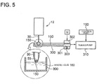
- FIG. 5 An example of a structure of the waste liquid tank 300 is illustrated in Fig. 5 , and the waste liquid tank 300 has a gutter-shaped member having a U-shaped cross section.
- One end 301 of the waste liquid tank 300 is fixed to a holder 302, and the holder 302 is movable in the X-axis direction along a guide bar 303.
- the guide bar 303 is fixed to the plate 200 along the X-axis direction in the lateral part of the plate 200
- a mechanism using a motor and a lead screw may be used as an apparatus for moving and positioning the waste liquid tank 300 in the X-axis direction.
- an operation of a motor M is controlled by an instruction of the control part 100.
- the lead screw is disposed in parallel with the guide bar 303. As the lead screw rotates by an operation of the motor M, the waste liquid tank 300 moves in the X-axis direction and is positioned.
- the waste liquid tank 300 is used to discard the liquid 150 containing the specimen ejected from the nozzle 30 into a waste liquid 160 according to a need.
- the liquid 150 ejected from the front end opening part 55 contains the unnecessary specimen SR
- the liquid 150 oozing from the nozzle front end comes in contact with the surface of the waste liquid 160 and is discarded.
- the waste liquid 160 is slowly drained from the waste liquid tank 300 by an operation of a tubing pump 310, and the waste liquid 300 is typically filled with the waste liquid 160.
- the waste liquid is certainly absorbed by the tubing pump 310 not to overflow from the waste liquid tank 300. Thus, the waste liquid does not leak from the waste liquid tank 300.
- the nozzle 30 comes in direct contact with the waste liquid 160.
- the culture solution in the well W may be contaminated through the nozzle 300.
- the front end outlet part 55 of the nozzle 30 does not come in contact with the waste liquid 160 in the waste liquid tank 300. Thus, it is possible to prevent contamination of the culture solution in the well W.
- the movement operation part 250 illustrated in Fig. 1 can move and position the plate 200 in the X-axis direction, the Y-axis direction, and the Z-axis direction.
- the X-axis direction (a first direction), the Y-axis direction (a second direction), and the Z-axis direction (a third direction) are orthogonal to each other.
- the Z-axis direction is the vertical direction.
- a typically used three-axis movement table such as an X-Y-Z table may be used.
- Fig. 1 illustrates a standby state of the specimen identification and dispensation device 10.
- the nozzle 30 is disposed below the optical measurement device 12 toward the Z1 direction.
- the nozzle 30 is disposed at a position corresponding to the waste liquid tank 300.
- the waste liquid tank 300 is positioned at a standby position in the center of the plate 200 in the X-axis direction.
- Fig. 7 illustrates a state in which the waste liquid tank 300 moved down and evacuated from the standby position P1 of Fig. 1 .
- the movement operation part 250 operates by an instruction of the control part 100, the plate 200 and the waste liquid tank 300 integrally move down in the Z1 direction and are positioned at an evacuation position P2.
- Fig. 8 illustrates a state a state in which the waste liquid tank 300 further evacuated from the evacuation position P2 of Fig. 7 in the X1 direction.
- the waste liquid tank 300 moves in the X1 direction (the left direction in the paper plane in Fig. 8 ) with respect to the plate 200 and is positioned at an evacuation position P3.
- the waste liquid tank 300 is at a position distant from the nozzle 30.
- Fig. 9 illustrates a state in which the plate 200 and the waste liquid tank 300 moved up in a Z2 direction.
- the plate 200 and the waste liquid tank 300 are moved up in the Z2 direction and positioned at a dispensation position P4.
- the liquid 150 oozing from the front end opening part 55 of the nozzle 30 comes in contact with the culture solution 70 in the selected well W, so that the liquid 150 containing the specimen S is dispensed into the well W.
- the other end (the lower end) 50 of the nozzle 30 has a taper shape, and the other end 50 does not come in direct contact with the culture solution 70.
- contaminated substances can be certainly prevented from getting mixed into the culture solution 70 and the specimen S from the nozzle 30 side.
- Fig. 10 illustrates a state in which the plate 200 and the waste liquid tank 300 moved down in the Z1 direction again.
- the well W is position at a falling position P5 distant from the nozzle 30.
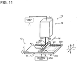
- Fig. 11 illustrates a state in which the waste liquid tank 300 is positioned at a standby position P6 below the nozzle 30 again.
- the waste liquid tank 300 moves in an X2 direction and moves toward the standby position P6.
- the plate 200 moves along the X1 direction reverse to the X2 direction by an arrangement pitch of the well.
- the nozzle 30 is relatively positioned above an arbitrary well W1 that is at a next position.
- the waste liquid tank 300 moves in the X2 direction, and at the same time, the plate 200 moves in the X1 direction by the arrangement pitch of the well.
- a time required to relatively position the nozzle 30 above the well W1 of the next candidate can be reduced.
- Fig. 12 illustrates a standby state in which the plate 200 and the waste liquid tank 300 moved up in the Z2 direction.
- the movement operation part 250 operates according to an instruction of the control part 100, the plate 200 and the waste liquid tank 300 are moved up in the Z2 direction to be positioned at a standby position P6.
- the nozzle 30 can dispense the liquid 150 into the well, at an arbitrary position, on the plate 200 by performing a series of such operations.
- Fig. 11 in order to dispense the liquid 150 into the well W2 other than the well W1, by operating the movement operation part 250 according to an instruction of the control part 100, the plate 200 and the waste liquid tank 300 move in the Y1 direction by the arrangement pitch of the well and are positioned.
- the waste liquid tank 300 moves by the movement of the Z-axis direction together with the plate 200.
- the waste liquid tank 300 may move and is positioned separately from the plate 200.
- the nozzle 30 does not move, and a position of the nozzle 30 is fixed. Instead, the units of the plate 200 and the waste liquid tank 300 of the dispensation part 13 move along the X-axis direction, the Y-axis direction, and the Z-axis direction of the movement operation part 250.
- Fig. 17 illustrates a comparative example of a structure of a dispensation part 1000 that is conventionally used.
- a dispensation part 1000 applies ultrasonic vibration to the specimen 1002 to form liquid droplets. For example, an electric charge of several hundred volts is applied. A voltage of several thousand volts is applied from a deflection plate to divide a drop position of each liquid droplet into a positive pole side and a negative pole side, causing dispensation into a well 1003 in the dispensation part. At the time of dispensation, high frequency vibration and a high voltage of several thousand volts are applied to the specimen 1002. For this reason, when a living cell is used as the specimen, a death rate of the specimen after dispensation is high, and even though the specimen is alive, the normal condition of the specimen is not certainly guaranteed.
- the specimen identification and dispensation device 100 using the specimen identification and dispensation device 100 according to the exemplary embodiment of the present invention, such an electric charge or voltage is not applied, and the plate 200 side of the dispensation part 13 is movable in the X-axis direction, the Y-axis direction, and the Z-axis direction.
- the specimen can be rapidly dispensed into a predetermined specimen dispensation position without having a bad influence on the specimen.
- the plate 200 side moves.
- a problem that the specimen leaks from the nozzle 30 does not rise.
- the flow passage formed by the optical measurement device 12 as the identification part and the nozzle 30 is formed in the form of the straight line.
- the flow velocity of the specimen S can be further stabilized, thereby increasing the degree of accuracy at the time of optical measurement of the specimen.
- the specimen identification and dispensation device 10 includes the optical measurement device 12 that is the identification part for identifying the specimen S by irradiating the exciting light L to the specimen S as a measurement object that is dispersed in the liquid flowing inside the capillary as the flow passage and measuring light information of the specimen S and the dispensation part 13 for dispensing the identified specimen S into the well W that is a dispensation target section through the nozzle 30.
- the dispensation part 13 is movable three-dimensionally with respect to the identification part 12 and the nozzle 30.
- the dispensation target section is a plurality of wells W formed in the plate 200.
- the culture solution 70 as a storage liquid into which the specimen S is immersed is stored in the well W.
- the liquid containing the specimen S ejected from the front end opening part 55 of the nozzle 30 comes in contact with the culture solution in the well W and is dispensed.
- the nozzle 30 can dispense the liquid containing the specimen S without directly contacting the culture solution 70.
- the specimen can be rapidly dispensed into a predetermined specimen dispensation position without causing the specimen and the culture solution to be contaminated nor having an influence on the specimen.
- the liquid containing the specimen has a hemispherical shape
- the specimen is a cell
- the storage liquid in the well is a culture solution.
- a portion of the nozzle in which the front end opening part is formed is formed with the taper shape.
- the flow passage of the nozzle 30 is larger than the flow passage of the optical measurement device 12.
- the flow velocity of the liquid containing the specimen S can be reduced.
- the flow velocity can be stabilized, and the light information of the specimen S can be obtained with the high degree of certainty.
- the specimen identification and dispensation device 10 includes the supply part 11 for separating the specimen S and supplying the specimen S to the optical measurement device 12.
- the flow passage of the specimen S formed by the optical measurement device 12 and the nozzle 30 is formed in the form of the straight line.
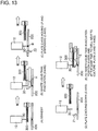
- Fig. 13 illustrates another example of an operation in which the waste liquid tank 300 returns to the standby position after evacuation.
- Fig. 13A the front end of the nozzle 30 is immerged into the waste liquid in the waste liquid tank 300.
- Fig. 13B as indicated by an arrow H, the waste liquid tank 300 slightly moves down once, so that the front end of the nozzle 30 is evacuated from the inside of the waste liquid tank 300, and thereafter the waste liquid tank 300 moves up and evacuates backward.
- the waste liquid tank 300 can evacuate backward without contacting the nozzle 30.
- the plate 200 moves up in the Z2 direction, and the front end of the nozzle 30 is inserted into the well W, so that the specimen S can be dispensed.
- the plate 200 moves down in the Z1 direction, so that the front end of the nozzle 30 is separated from the well W.
- the waste liquid tank 300 moves in a G direction, and the front end of the nozzle 30 is inserted into the waste liquid tank 300, so that the waste liquid tank 300 returns to the standby position.
- the plate 200 moves so that the specimen can be dispensed into the next well.
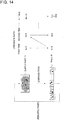
- Fig. 14 is a view illustrating a change in presence rate of the target specimen according to the dispensation process.
- the dispensation process increases the presence rate M 0 % of the target specimen supplied from the supply part 11 of Fig. 1 to the presence rate M 1 % of the specimen S that is to be dispensed into the well W of the dispensation part 12 of Fig. 1 .
- the presence rate of the target specimen to be dispensed in to the well W of the dispensation part 13 of Fig. 1 gradually increases.
- the presence rate M n % of the target specimen to be dispensed into the well W of the dispensation part 13 becomes 100%, and the specimen is dispensed into the well W one by one.
- the specimen identification and dispensation device 100 concentrates the sample liquid in a stepwise fashion, that is, increases the presence rate of the target specimen to make the appropriate concentration (the sample liquid concentration) of the specimen contained in the sample liquid and then dispenses the target specimen one by one.
- the number of times of the operation work of the dispensation part 13 of Fig. 1 in which the operation time is expended is reduced, thereby reducing the dispensation process time.
- Fig. 15 is a view for explaining the embodiment example.
- Fig. 16 illustrates a result of the dispensation process of the embodiment example.
- the sample liquid amount 100 ⁇ l in which the concentration in which total 100,000 cells including 10 target cells are dispersed is 1000cells/ ⁇ l was supplied from the supply part 11 of Fig. 1 , and 75 cells includes at least one target cell were dispensed into each of 10 well W.
- the presence rate of the target cell in the supply part 11 of Fig. 1 was 0.01%, but the presence rate of the target cell dispensed into the well W of the dispensation part 13 of Fig. 1 became 1.33%.
- the time expended in the first-time dispensation work was 11.1 minutes.
- the storage liquid in the well W was 50 ⁇ l, and the liquid amount in the well W was 80 ⁇ l.
- the light receiving part 42 illustrated in Fig. 1 is disposed at a positions opposite to the optical fiber 40 with the capillary 21 interposed therebetween.
- the present invention is not limited thereto, but the light receiving part 42 may be disposed at a position of a side of the capillary 21 (a position of a direction perpendicular to the paper plane in Fig. 1 ).
- the capillary 21 illustrated in FIGs. 1 and 2 is a hollow member having, for example, a rectangular cross section but may have a cross section of any other shape.
- the dispensation part 13 is a plate, but not limited to a plate, and may be a tube or a dish.
- the resupply part may not be disposed in the specimen identification and dispensation device as a mechanism, and it is preferable to supply the dispensed specimen to the optical measurement device 12 once again through the resupply part 13.
- a signal such as scattered light, transmitted light, and fluorescent light information obtained from the specimen S, for example, the cell can be acquired by using the light receiving part 42.
- the transparent member is not limited to a glass plate, and any other transparent material such as a transparent plastic plate may be used.
- the nozzle 30 may be not vertical but tilted to the waste liquid tank 300 as illustrated in the drawings.
- the exciting light can be referred to as measurement light or irradiation light.
- the optical measurement device of the present invention can be applied to all fields such as a field that requires inspection and analysis on a biological polymer of a gene, an immunity system, protein, an amino acid, and sugar like an engineering field, an agriculture field including food product, agriculture product, and seafood processing, a medicine field, a medical field including hygiene, health, immunity, plague, and heredity, and a physical science field including chemistry and biology.
Applications Claiming Priority (1)
| Application Number | Priority Date | Filing Date | Title |
|---|---|---|---|
| PCT/JP2008/062421 WO2010004627A1 (ja) | 2008-07-09 | 2008-07-09 | 検体識別分注装置及び検体識別分注方法 |
Publications (3)
| Publication Number | Publication Date |
|---|---|
| EP2299253A1 EP2299253A1 (en) | 2011-03-23 |
| EP2299253A4 EP2299253A4 (en) | 2017-10-18 |
| EP2299253B1 true EP2299253B1 (en) | 2019-01-02 |
Family
ID=41506761
Family Applications (1)
| Application Number | Title | Priority Date | Filing Date |
|---|---|---|---|
| EP08791008.9A Not-in-force EP2299253B1 (en) | 2008-07-09 | 2008-07-09 | Specimen identification and dispensation device and specimen identification and dispensation method |
Country Status (4)
| Country | Link |
|---|---|
| US (1) | US9314788B2 (ja) |
| EP (1) | EP2299253B1 (ja) |
| CN (1) | CN102077071B (ja) |
| WO (1) | WO2010004627A1 (ja) |
Families Citing this family (15)
| Publication number | Priority date | Publication date | Assignee | Title |
|---|---|---|---|---|
| EP2577254B1 (en) | 2010-06-10 | 2015-02-25 | Albert-Ludwigs-Universität Freiburg | Apparatus and method for dispensing cells or particles confined in a free flying droplet |
| CN102890159B (zh) * | 2012-07-06 | 2014-09-03 | 深圳市麦迪聪医疗电子有限公司 | 一种自动样品识别的采样系统及其方法 |
| EP2703820B1 (en) * | 2012-08-31 | 2019-08-28 | F. Hoffmann-La Roche AG | Mobile tip waste rack |
| WO2014038640A1 (ja) * | 2012-09-06 | 2014-03-13 | 古河電気工業株式会社 | 検体識別分取装置および検体識別分取方法 |
| KR102161604B1 (ko) * | 2014-02-12 | 2020-10-06 | 삼성디스플레이 주식회사 | 용액 제공 장치 및 이를 이용하는 유기전계발광 표시장치의 제조 방법 |
| CN104006984A (zh) * | 2014-06-04 | 2014-08-27 | 上海宏莘科技发展有限公司 | 数码式全自动智能取样机 |
| WO2016078339A1 (zh) * | 2014-11-17 | 2016-05-26 | 中国科学院微生物研究所 | 微液滴生成装置、系统、方法及单细胞/单分子分析装置 |
| US11725179B2 (en) | 2015-05-12 | 2023-08-15 | On-Chip Biotechnologies Co., Ltd. | Single-particle analysis method, and system for performing said analysis |
| US10322545B1 (en) * | 2016-09-08 | 2019-06-18 | The United States Of America As Represented By The Director, National Security Agency | Measuring ink stream deposition rate of an aerosol-jet printer |
| CN108514895A (zh) * | 2018-03-01 | 2018-09-11 | 北京天健惠康生物科技有限公司 | 一种微液滴生成及监测装置 |
| CN108802410B (zh) * | 2018-03-22 | 2021-07-02 | 广州市第一人民医院(广州消化疾病中心、广州医科大学附属市一人民医院、华南理工大学附属第二医院) | 一种液滴芯片细胞分析系统及其分析方法 |
| CN109633051A (zh) * | 2019-02-19 | 2019-04-16 | 安徽皖仪科技股份有限公司 | 自动进样器、液相色谱仪和液相色谱仪自动进样方法 |
| US20210247411A1 (en) * | 2020-02-10 | 2021-08-12 | Funai Electric Co., Ltd. | Maintenance Reservoir |
| CN112924364A (zh) * | 2021-01-22 | 2021-06-08 | 贝克曼库尔特生物科技(苏州)有限公司 | 喷嘴、载体、喷嘴组件及样本处理仪 |
| DE102021202518B3 (de) | 2021-03-15 | 2022-08-18 | Lpkf Laser & Electronics Aktiengesellschaft | Vorrichtung und Verfahren zum Absetzen von Flüssigkeit auf Träger |
Family Cites Families (11)
| Publication number | Priority date | Publication date | Assignee | Title |
|---|---|---|---|---|
| JPS6135331A (ja) | 1984-07-28 | 1986-02-19 | Japan Spectroscopic Co | 微小粒子分離装置 |
| AU2788101A (en) * | 2000-01-11 | 2001-07-24 | Maxygen, Inc. | Integrated systems and methods for diversity generation and screening |
| US6387330B1 (en) * | 2000-04-12 | 2002-05-14 | George Steven Bova | Method and apparatus for storing and dispensing reagents |
| JP2003284544A (ja) * | 2002-03-29 | 2003-10-07 | Aisin Seiki Co Ltd | 細胞分離選別装置、細胞整列用基板 |
| WO2005071386A1 (ja) * | 2004-01-23 | 2005-08-04 | Hitachi Plant Technologies, Ltd. | 微生物分離装置 |
| WO2005085775A1 (en) * | 2004-02-06 | 2005-09-15 | Seyonic S.A. | Pipette verification device and pipette |
| JP2005249585A (ja) | 2004-03-04 | 2005-09-15 | Olympus Corp | 自動分析装置及び分析方法 |
| US8264674B2 (en) | 2004-04-23 | 2012-09-11 | The Furukawa Electric Co., Ltd. | Methods of separating, identifying and dispensing specimen and device therefor, and analyzing device method |
| US7355696B2 (en) * | 2005-02-01 | 2008-04-08 | Arryx, Inc | Method and apparatus for sorting cells |
| WO2006110725A2 (en) * | 2005-04-09 | 2006-10-19 | Cell Biosciences, Inc. | Automated micro-volume assay system |
| US7901624B2 (en) * | 2006-09-26 | 2011-03-08 | Becton, Dickinson And Company | Device for automatically adjusting the bacterial inoculum level of a sample |
-
2008
- 2008-07-09 EP EP08791008.9A patent/EP2299253B1/en not_active Not-in-force
- 2008-07-09 US US13/003,403 patent/US9314788B2/en active Active
- 2008-07-09 WO PCT/JP2008/062421 patent/WO2010004627A1/ja active Application Filing
- 2008-07-09 CN CN2008801300881A patent/CN102077071B/zh active Active
Non-Patent Citations (1)
| Title |
|---|
| None * |
Also Published As
| Publication number | Publication date |
|---|---|
| WO2010004627A1 (ja) | 2010-01-14 |
| EP2299253A1 (en) | 2011-03-23 |
| CN102077071B (zh) | 2013-10-09 |
| US9314788B2 (en) | 2016-04-19 |
| EP2299253A4 (en) | 2017-10-18 |
| CN102077071A (zh) | 2011-05-25 |
| US20110177489A1 (en) | 2011-07-21 |
Similar Documents
| Publication | Publication Date | Title |
|---|---|---|
| EP2299253B1 (en) | Specimen identification and dispensation device and specimen identification and dispensation method | |
| JP7354368B2 (ja) | マイクロ流体チャネルを使用してマイクロ粒子のバルク選別を行う方法及び装置 | |
| EP1739402B1 (en) | Methods of separating, identifying and dispensing specimen and device therefor, and analyzing device method | |
| WO2017061387A1 (ja) | 試料採取システム | |
| CN113474084B (zh) | 用于液滴检测的系统和方法 | |
| CN112384809A (zh) | 流体自动采样器和培育器 | |
| US20120097582A1 (en) | Sample identification/sorting apparatus and sample identification/sorting method | |
| US20120308436A1 (en) | Analysis system of biological particles in liquid flow | |
| US11446651B2 (en) | Method and apparatus for single particle deposition | |
| JP4976209B2 (ja) | 検体識別分注装置及び検体識別分注方法 | |
| US9329195B2 (en) | Container cleaning device, discharge member for container cleaning device, and analyzer | |
| CN109959549A (zh) | 样本检测方法及样本分析仪 | |
| US20190161719A1 (en) | Liquid feeding device and method for feeding liquid | |
| US20230415153A1 (en) | Microfluidic devices and method for sampling and analysis of cells using optical forces and raman spectroscopy | |
| WO2015178124A1 (ja) | 粒子分析装置 | |
| US7186382B2 (en) | Microchip apparatus | |
| US11524286B2 (en) | Method and metering device for the contact metering of liquids | |
| CN116157500A (zh) | 采样设备和系统 | |
| JP2021166982A (ja) | 液滴搬送デバイス、分析システム及び分析方法 | |
| CN111936865A (zh) | 流体处理装置 |
Legal Events
| Date | Code | Title | Description |
|---|---|---|---|
| PUAI | Public reference made under article 153(3) epc to a published international application that has entered the european phase |
Free format text: ORIGINAL CODE: 0009012 |
|
| 17P | Request for examination filed |
Effective date: 20110120 |
|
| AK | Designated contracting states |
Kind code of ref document: A1 Designated state(s): AT BE BG CH CY CZ DE DK EE ES FI FR GB GR HR HU IE IS IT LI LT LU LV MC MT NL NO PL PT RO SE SI SK TR |
|
| AX | Request for extension of the european patent |
Extension state: AL BA MK RS |
|
| RIN1 | Information on inventor provided before grant (corrected) |
Inventor name: TSUKII, KEN Inventor name: XU, JIE Inventor name: TAKAHASHI, TORU |
|
| DAX | Request for extension of the european patent (deleted) | ||
| RA4 | Supplementary search report drawn up and despatched (corrected) |
Effective date: 20170920 |
|
| RIC1 | Information provided on ipc code assigned before grant |
Ipc: G01N 35/10 20060101ALI20170914BHEP Ipc: G01N 1/00 20060101AFI20170914BHEP Ipc: C12M 1/34 20060101ALI20170914BHEP |
|
| GRAP | Despatch of communication of intention to grant a patent |
Free format text: ORIGINAL CODE: EPIDOSNIGR1 |
|
| STAA | Information on the status of an ep patent application or granted ep patent |
Free format text: STATUS: GRANT OF PATENT IS INTENDED |
|
| INTG | Intention to grant announced |
Effective date: 20180710 |
|
| GRAS | Grant fee paid |
Free format text: ORIGINAL CODE: EPIDOSNIGR3 |
|
| GRAA | (expected) grant |
Free format text: ORIGINAL CODE: 0009210 |
|
| STAA | Information on the status of an ep patent application or granted ep patent |
Free format text: STATUS: THE PATENT HAS BEEN GRANTED |
|
| AK | Designated contracting states |
Kind code of ref document: B1 Designated state(s): AT BE BG CH CY CZ DE DK EE ES FI FR GB GR HR HU IE IS IT LI LT LU LV MC MT NL NO PL PT RO SE SI SK TR |
|
| REG | Reference to a national code |
Ref country code: GB Ref legal event code: FG4D |
|
| REG | Reference to a national code |
Ref country code: CH Ref legal event code: EP Ref country code: AT Ref legal event code: REF Ref document number: 1085007 Country of ref document: AT Kind code of ref document: T Effective date: 20190115 |
|
| REG | Reference to a national code |
Ref country code: DE Ref legal event code: R096 Ref document number: 602008058600 Country of ref document: DE |
|
| REG | Reference to a national code |
Ref country code: IE Ref legal event code: FG4D |
|
| REG | Reference to a national code |
Ref country code: NL Ref legal event code: MP Effective date: 20190102 |
|
| REG | Reference to a national code |
Ref country code: LT Ref legal event code: MG4D |
|
| REG | Reference to a national code |
Ref country code: AT Ref legal event code: MK05 Ref document number: 1085007 Country of ref document: AT Kind code of ref document: T Effective date: 20190102 |
|
| PG25 | Lapsed in a contracting state [announced via postgrant information from national office to epo] |
Ref country code: NL Free format text: LAPSE BECAUSE OF FAILURE TO SUBMIT A TRANSLATION OF THE DESCRIPTION OR TO PAY THE FEE WITHIN THE PRESCRIBED TIME-LIMIT Effective date: 20190102 |
|
| PG25 | Lapsed in a contracting state [announced via postgrant information from national office to epo] |
Ref country code: PT Free format text: LAPSE BECAUSE OF FAILURE TO SUBMIT A TRANSLATION OF THE DESCRIPTION OR TO PAY THE FEE WITHIN THE PRESCRIBED TIME-LIMIT Effective date: 20190502 Ref country code: ES Free format text: LAPSE BECAUSE OF FAILURE TO SUBMIT A TRANSLATION OF THE DESCRIPTION OR TO PAY THE FEE WITHIN THE PRESCRIBED TIME-LIMIT Effective date: 20190102 Ref country code: SE Free format text: LAPSE BECAUSE OF FAILURE TO SUBMIT A TRANSLATION OF THE DESCRIPTION OR TO PAY THE FEE WITHIN THE PRESCRIBED TIME-LIMIT Effective date: 20190102 Ref country code: PL Free format text: LAPSE BECAUSE OF FAILURE TO SUBMIT A TRANSLATION OF THE DESCRIPTION OR TO PAY THE FEE WITHIN THE PRESCRIBED TIME-LIMIT Effective date: 20190102 Ref country code: NO Free format text: LAPSE BECAUSE OF FAILURE TO SUBMIT A TRANSLATION OF THE DESCRIPTION OR TO PAY THE FEE WITHIN THE PRESCRIBED TIME-LIMIT Effective date: 20190402 Ref country code: LT Free format text: LAPSE BECAUSE OF FAILURE TO SUBMIT A TRANSLATION OF THE DESCRIPTION OR TO PAY THE FEE WITHIN THE PRESCRIBED TIME-LIMIT Effective date: 20190102 Ref country code: FI Free format text: LAPSE BECAUSE OF FAILURE TO SUBMIT A TRANSLATION OF THE DESCRIPTION OR TO PAY THE FEE WITHIN THE PRESCRIBED TIME-LIMIT Effective date: 20190102 |
|
| PG25 | Lapsed in a contracting state [announced via postgrant information from national office to epo] |
Ref country code: GR Free format text: LAPSE BECAUSE OF FAILURE TO SUBMIT A TRANSLATION OF THE DESCRIPTION OR TO PAY THE FEE WITHIN THE PRESCRIBED TIME-LIMIT Effective date: 20190403 Ref country code: BG Free format text: LAPSE BECAUSE OF FAILURE TO SUBMIT A TRANSLATION OF THE DESCRIPTION OR TO PAY THE FEE WITHIN THE PRESCRIBED TIME-LIMIT Effective date: 20190402 Ref country code: HR Free format text: LAPSE BECAUSE OF FAILURE TO SUBMIT A TRANSLATION OF THE DESCRIPTION OR TO PAY THE FEE WITHIN THE PRESCRIBED TIME-LIMIT Effective date: 20190102 Ref country code: IS Free format text: LAPSE BECAUSE OF FAILURE TO SUBMIT A TRANSLATION OF THE DESCRIPTION OR TO PAY THE FEE WITHIN THE PRESCRIBED TIME-LIMIT Effective date: 20190502 Ref country code: LV Free format text: LAPSE BECAUSE OF FAILURE TO SUBMIT A TRANSLATION OF THE DESCRIPTION OR TO PAY THE FEE WITHIN THE PRESCRIBED TIME-LIMIT Effective date: 20190102 |
|
| REG | Reference to a national code |
Ref country code: DE Ref legal event code: R097 Ref document number: 602008058600 Country of ref document: DE |
|
| PG25 | Lapsed in a contracting state [announced via postgrant information from national office to epo] |
Ref country code: RO Free format text: LAPSE BECAUSE OF FAILURE TO SUBMIT A TRANSLATION OF THE DESCRIPTION OR TO PAY THE FEE WITHIN THE PRESCRIBED TIME-LIMIT Effective date: 20190102 Ref country code: SK Free format text: LAPSE BECAUSE OF FAILURE TO SUBMIT A TRANSLATION OF THE DESCRIPTION OR TO PAY THE FEE WITHIN THE PRESCRIBED TIME-LIMIT Effective date: 20190102 Ref country code: IT Free format text: LAPSE BECAUSE OF FAILURE TO SUBMIT A TRANSLATION OF THE DESCRIPTION OR TO PAY THE FEE WITHIN THE PRESCRIBED TIME-LIMIT Effective date: 20190102 Ref country code: CZ Free format text: LAPSE BECAUSE OF FAILURE TO SUBMIT A TRANSLATION OF THE DESCRIPTION OR TO PAY THE FEE WITHIN THE PRESCRIBED TIME-LIMIT Effective date: 20190102 Ref country code: EE Free format text: LAPSE BECAUSE OF FAILURE TO SUBMIT A TRANSLATION OF THE DESCRIPTION OR TO PAY THE FEE WITHIN THE PRESCRIBED TIME-LIMIT Effective date: 20190102 Ref country code: DK Free format text: LAPSE BECAUSE OF FAILURE TO SUBMIT A TRANSLATION OF THE DESCRIPTION OR TO PAY THE FEE WITHIN THE PRESCRIBED TIME-LIMIT Effective date: 20190102 Ref country code: AT Free format text: LAPSE BECAUSE OF FAILURE TO SUBMIT A TRANSLATION OF THE DESCRIPTION OR TO PAY THE FEE WITHIN THE PRESCRIBED TIME-LIMIT Effective date: 20190102 |
|
| PLBE | No opposition filed within time limit |
Free format text: ORIGINAL CODE: 0009261 |
|
| STAA | Information on the status of an ep patent application or granted ep patent |
Free format text: STATUS: NO OPPOSITION FILED WITHIN TIME LIMIT |
|
| 26N | No opposition filed |
Effective date: 20191003 |
|
| PG25 | Lapsed in a contracting state [announced via postgrant information from national office to epo] |
Ref country code: MC Free format text: LAPSE BECAUSE OF FAILURE TO SUBMIT A TRANSLATION OF THE DESCRIPTION OR TO PAY THE FEE WITHIN THE PRESCRIBED TIME-LIMIT Effective date: 20190102 Ref country code: SI Free format text: LAPSE BECAUSE OF FAILURE TO SUBMIT A TRANSLATION OF THE DESCRIPTION OR TO PAY THE FEE WITHIN THE PRESCRIBED TIME-LIMIT Effective date: 20190102 |
|
| REG | Reference to a national code |
Ref country code: CH Ref legal event code: PL |
|
| PG25 | Lapsed in a contracting state [announced via postgrant information from national office to epo] |
Ref country code: TR Free format text: LAPSE BECAUSE OF FAILURE TO SUBMIT A TRANSLATION OF THE DESCRIPTION OR TO PAY THE FEE WITHIN THE PRESCRIBED TIME-LIMIT Effective date: 20190102 |
|
| REG | Reference to a national code |
Ref country code: BE Ref legal event code: MM Effective date: 20190731 |
|
| PG25 | Lapsed in a contracting state [announced via postgrant information from national office to epo] |
Ref country code: CH Free format text: LAPSE BECAUSE OF NON-PAYMENT OF DUE FEES Effective date: 20190731 Ref country code: BE Free format text: LAPSE BECAUSE OF NON-PAYMENT OF DUE FEES Effective date: 20190731 Ref country code: LU Free format text: LAPSE BECAUSE OF NON-PAYMENT OF DUE FEES Effective date: 20190709 Ref country code: LI Free format text: LAPSE BECAUSE OF NON-PAYMENT OF DUE FEES Effective date: 20190731 |
|
| PG25 | Lapsed in a contracting state [announced via postgrant information from national office to epo] |
Ref country code: FR Free format text: LAPSE BECAUSE OF NON-PAYMENT OF DUE FEES Effective date: 20190731 |
|
| PG25 | Lapsed in a contracting state [announced via postgrant information from national office to epo] |
Ref country code: IE Free format text: LAPSE BECAUSE OF NON-PAYMENT OF DUE FEES Effective date: 20190709 |
|
| PG25 | Lapsed in a contracting state [announced via postgrant information from national office to epo] |
Ref country code: CY Free format text: LAPSE BECAUSE OF FAILURE TO SUBMIT A TRANSLATION OF THE DESCRIPTION OR TO PAY THE FEE WITHIN THE PRESCRIBED TIME-LIMIT Effective date: 20190102 |
|
| PG25 | Lapsed in a contracting state [announced via postgrant information from national office to epo] |
Ref country code: MT Free format text: LAPSE BECAUSE OF FAILURE TO SUBMIT A TRANSLATION OF THE DESCRIPTION OR TO PAY THE FEE WITHIN THE PRESCRIBED TIME-LIMIT Effective date: 20190102 Ref country code: HU Free format text: LAPSE BECAUSE OF FAILURE TO SUBMIT A TRANSLATION OF THE DESCRIPTION OR TO PAY THE FEE WITHIN THE PRESCRIBED TIME-LIMIT; INVALID AB INITIO Effective date: 20080709 |
|
| PGFP | Annual fee paid to national office [announced via postgrant information from national office to epo] |
Ref country code: GB Payment date: 20210616 Year of fee payment: 14 |
|
| PGFP | Annual fee paid to national office [announced via postgrant information from national office to epo] |
Ref country code: DE Payment date: 20210616 Year of fee payment: 14 |
|
| REG | Reference to a national code |
Ref country code: DE Ref legal event code: R119 Ref document number: 602008058600 Country of ref document: DE |
|
| GBPC | Gb: european patent ceased through non-payment of renewal fee |
Effective date: 20220709 |
|
| PG25 | Lapsed in a contracting state [announced via postgrant information from national office to epo] |
Ref country code: GB Free format text: LAPSE BECAUSE OF NON-PAYMENT OF DUE FEES Effective date: 20220709 Ref country code: DE Free format text: LAPSE BECAUSE OF NON-PAYMENT OF DUE FEES Effective date: 20230201 |