EP2299115A2 - Linear elektrischer Kompressor und Kühlmittelschaltung - Google Patents
Linear elektrischer Kompressor und Kühlmittelschaltung Download PDFInfo
- Publication number
- EP2299115A2 EP2299115A2 EP10174597A EP10174597A EP2299115A2 EP 2299115 A2 EP2299115 A2 EP 2299115A2 EP 10174597 A EP10174597 A EP 10174597A EP 10174597 A EP10174597 A EP 10174597A EP 2299115 A2 EP2299115 A2 EP 2299115A2
- Authority
- EP
- European Patent Office
- Prior art keywords
- piston
- refrigerant circuit
- linear electric
- electric compressor
- cylinder bore
- Prior art date
- Legal status (The legal status is an assumption and is not a legal conclusion. Google has not performed a legal analysis and makes no representation as to the accuracy of the status listed.)
- Withdrawn
Links
- 239000003507 refrigerant Substances 0.000 title claims abstract description 92
- 230000006835 compression Effects 0.000 claims description 25
- 238000007906 compression Methods 0.000 claims description 25
- 230000004308 accommodation Effects 0.000 claims description 8
- 230000004907 flux Effects 0.000 claims description 6
- 125000006850 spacer group Chemical group 0.000 description 9
- 230000007423 decrease Effects 0.000 description 5
- 238000011144 upstream manufacturing Methods 0.000 description 5
- 230000001276 controlling effect Effects 0.000 description 4
- 230000002093 peripheral effect Effects 0.000 description 4
- 230000000694 effects Effects 0.000 description 3
- 235000014676 Phragmites communis Nutrition 0.000 description 2
- 238000004378 air conditioning Methods 0.000 description 2
- 238000005452 bending Methods 0.000 description 2
- 239000012530 fluid Substances 0.000 description 1
- WABPQHHGFIMREM-UHFFFAOYSA-N lead(0) Chemical compound [Pb] WABPQHHGFIMREM-UHFFFAOYSA-N 0.000 description 1
- 239000000696 magnetic material Substances 0.000 description 1
- 238000004519 manufacturing process Methods 0.000 description 1
- 239000000463 material Substances 0.000 description 1
- 230000000737 periodic effect Effects 0.000 description 1
- 239000004810 polytetrafluoroethylene Substances 0.000 description 1
- 229920001343 polytetrafluoroethylene Polymers 0.000 description 1
- 229910052761 rare earth metal Inorganic materials 0.000 description 1
- 150000002910 rare earth metals Chemical class 0.000 description 1
- 230000001105 regulatory effect Effects 0.000 description 1
Images






Classifications
-
- F—MECHANICAL ENGINEERING; LIGHTING; HEATING; WEAPONS; BLASTING
- F04—POSITIVE - DISPLACEMENT MACHINES FOR LIQUIDS; PUMPS FOR LIQUIDS OR ELASTIC FLUIDS
- F04B—POSITIVE-DISPLACEMENT MACHINES FOR LIQUIDS; PUMPS
- F04B35/00—Piston pumps specially adapted for elastic fluids and characterised by the driving means to their working members, or by combination with, or adaptation to, specific driving engines or motors, not otherwise provided for
- F04B35/04—Piston pumps specially adapted for elastic fluids and characterised by the driving means to their working members, or by combination with, or adaptation to, specific driving engines or motors, not otherwise provided for the means being electric
- F04B35/045—Piston pumps specially adapted for elastic fluids and characterised by the driving means to their working members, or by combination with, or adaptation to, specific driving engines or motors, not otherwise provided for the means being electric using solenoids
-
- F—MECHANICAL ENGINEERING; LIGHTING; HEATING; WEAPONS; BLASTING
- F04—POSITIVE - DISPLACEMENT MACHINES FOR LIQUIDS; PUMPS FOR LIQUIDS OR ELASTIC FLUIDS
- F04B—POSITIVE-DISPLACEMENT MACHINES FOR LIQUIDS; PUMPS
- F04B39/00—Component parts, details, or accessories, of pumps or pumping systems specially adapted for elastic fluids, not otherwise provided for in, or of interest apart from, groups F04B25/00 - F04B37/00
- F04B39/12—Casings; Cylinders; Cylinder heads; Fluid connections
-
- F—MECHANICAL ENGINEERING; LIGHTING; HEATING; WEAPONS; BLASTING
- F04—POSITIVE - DISPLACEMENT MACHINES FOR LIQUIDS; PUMPS FOR LIQUIDS OR ELASTIC FLUIDS
- F04B—POSITIVE-DISPLACEMENT MACHINES FOR LIQUIDS; PUMPS
- F04B49/00—Control, e.g. of pump delivery, or pump pressure of, or safety measures for, machines, pumps, or pumping installations, not otherwise provided for, or of interest apart from, groups F04B1/00 - F04B47/00
- F04B49/06—Control using electricity
- F04B49/065—Control using electricity and making use of computers
-
- F—MECHANICAL ENGINEERING; LIGHTING; HEATING; WEAPONS; BLASTING
- F04—POSITIVE - DISPLACEMENT MACHINES FOR LIQUIDS; PUMPS FOR LIQUIDS OR ELASTIC FLUIDS
- F04B—POSITIVE-DISPLACEMENT MACHINES FOR LIQUIDS; PUMPS
- F04B2203/00—Motor parameters
- F04B2203/02—Motor parameters of rotating electric motors
- F04B2203/0203—Magnetic flux
-
- F—MECHANICAL ENGINEERING; LIGHTING; HEATING; WEAPONS; BLASTING
- F04—POSITIVE - DISPLACEMENT MACHINES FOR LIQUIDS; PUMPS FOR LIQUIDS OR ELASTIC FLUIDS
- F04B—POSITIVE-DISPLACEMENT MACHINES FOR LIQUIDS; PUMPS
- F04B2203/00—Motor parameters
- F04B2203/02—Motor parameters of rotating electric motors
- F04B2203/0204—Frequency of the electric current
Definitions
- the present invention relates to a linear electric compressor and also to a refrigerant circuit including the linear electric compressor.
- Japanese Patent No. 3953735 discloses a linear electric compressor which includes a double-headed piston including a piston rod and piston heads at the opposite ends of the piston rod and compression chambers formed at the outer end of each piston head.
- the linear electric compressor further includes permanent magnets provided at positions corresponding to the center of the piston rod of the double-headed piston and to each piston head thereof and coils provided around the piston rod and each piston head.
- the linear electric compressor still further includes a pair of springs provided inside the double-headed piston.
- the linear electric compressor By supplying electric power periodically to energize the coils of the linear electric compressor of the above Patent, periodically variable electromagnetic force is generated around the coils and the permanent magnets of the pistons are attracted toward or repelled from the coils by the electromagnetic force. Accordingly, the pistons reciprocate in cylinder bores. The pistons reciprocate also by resonance of natural frequency of the springs. The reciprocating movement of the pistons causes refrigerant gas to be introduced from a suction chamber to a compression chamber, compressed in the compression chamber and discharged into a discharge chamber.
- the linear electric compressor can be electrically controlled to compress refrigerant gas and used for an air conditioner for an electric vehicle and the like.
- this type of linear electric compressor can compress refrigerant gas twice by a single reciprocating movement of the piston and, therefore, the performance of compressing refrigerant gas per unit time can be improved and the compressor be made small as compared with a linear electric compressor having a compression chamber only at one end of the piston.
- linear electric compressor of the above Patent requires a space in the piston for installing the springs. Therefore, the outer diameter of the piston is increased and the inner diameter of the cylinder bore needs to be designed accordingly.
- This type of linear electric compressor has limitations on downsizing.
- the present invention is directed to providing a linear electric compressor that can be made small while ensuring the performance of compressing refrigerant gas per unit time and also a refrigerant circuit having the linear electric compressor.
- a refrigerant circuit includes a linear electric compressor including a housing with a cylinder bore, a pair of end plates, a valve unit, a piston, an urging device for urging the piston, a coil generating electromagnetic force and a permanent magnet.
- the permanent magnet cooperates with the urging device and the coil to reciprocate the piston in the cylinder bore.
- the piston further includes a piston rod and the urging device is provided around the piston rod and a pair of piston heads integrally formed at opposite ends of the piston rod. The diameter of the piston rod is smaller than that of the piston head.
- the permanent magnet is provided on the piston head and the coil surrounds the piston head.
- the housing further includes a seat located between the pair of piston heads and the urging device is provided between the seat and each of the piston head.
- linear electric compressor 100 according to the first embodiment and the refrigerant circuits 140, 200, 300 according to the first through the third embodiments, respectively, are employed for an air conditioner for a hybrid vehicle or an electric vehicle.
- the linear electric compressor 100 includes a first and a second cylinder blocks 1, 3, a shell 5 and a center housing 7, which cooperate to form a housing 9 of the linear electric compressor 100.
- the first and the second cylinder blocks 1, 3 have formed therein a first and a second cylinder bores 1A, 3A, respectively.
- the first and the second cylinder bores 1A, 3A are designed so that they are coaxially formed and have the same diameter.
- the first and the second cylinder blocks 1, 3 have a first and a second flanges 1B, 3B around the first and the second cylinder bores 1A, 3A, respectively, which are housed in the shell 5 so that the first and the second flanges 1B, 3B are located at the opposite ends of the shell 5.
- the center housing 7 is provided in the shell 5 between the first and the second cylinder blocks 1, 3.
- the center housing 7 has formed therethrough in axial direction thereof an accommodation hole 7A which is coaxial with the first and the second cylinder bores 1A, 3A and the diameter of which is substantially the same as those of the first and the second cylinder bores 1A, 3A.
- a first and a second end plates 11, 13 are joined to the opposite ends of the shell 5 through a first and a second gaskets 10, 12, respectively.
- the first and the second end plates 11, 13 have formed therein recesses, respectively and a first and a second valve plates 15, 17 are held between the first gasket 10 and the first end plate 11 and between the second gasket 12 and the second end plate 13, respectively.
- a first and a second discharge chambers 11A, 13A are formed by the recesses between the first and the second end plates 11, 13 and the first and the second valve plates 15, 17, respectively.
- the first and the second end plates 11, 13 have formed therethrough a first and a second discharge ports 11B, 13B, respectively.
- the first and the second discharge chambers 11A, 13A are connected to tubes 101, 102 shown in FIG. 2 through the first and the second discharge ports 11 B, 13B, respectively.
- the first and the second discharge chambers 11A, 13A form the discharge chamber of the present invention.
- the first valve plate 15 has formed therethrough a discharge port 15A.
- a reed type discharge valve 19 for opening and closing the discharge port 15A and a retainer 21 for regulating the opening of the discharge valve 19 are fixed by a rivet 23 to the first valve plate 15 on the first discharge port 11B side.
- the first valve plate 15, the discharge valve 19, the retainer 21 and the rivet 23 cooperate to form a first valve unit 25.
- a second valve unit is formed on the second valve plate 17 side.
- the first and the second valve units 25 are provided between the first and the second cylinder bores 1A, 3A and the first and the second end plates 11, 13, respectively.
- the first and the second cylinder bores 1A, 3A and the accommodation hole 7A receive therein a reciprocally slidable piston 27.
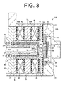
- the piston 27 includes a piston rod 29 and a first and a second piston heads 31, 33 which are integrally provided with the piston rod 29 at the opposite ends of the piston rod 29, respectively and slidable in the first and the second cylinder bores 1A, 3A, respectively.
- the first piston head 31 includes a head 39, on outer surface of which permanent magnets 35, 37 are fixed, and a first and a second spacers 41, 43 which are integrally provided with the head 39 and form a space between the inner surface of the first cylinder bore 1A and the outer surface of the permanent magnets 35, 37.
- the permanent magnets 35, 37 are ring shaped and use a rare-earth magnet. North and south poles of the permanent magnet 35 are located on the outer surface thereof and the inner surface thereof, respectively, and, on the other hand, south and north poles of the permanent magnet 37 are located on the outer surface thereof and the inner surface thereof, respectively.
- the polar character of the permanent magnets 35, 37 may be reversed.
- the permanent magnets 37, 35 In installing the permanent magnets 37, 35, firstly the second spacer 43 is press-fit on the head 39, the permanent magnets 37, 35 are press-fit on the outer surface of the head 39, and then the first spacer 41 is press-fit on the outer surface of the head 39, as shown in FIG. 3 . Thus, the permanent magnets 35, 37 are held securely on the outer surface of the head 39 between the first and the second spacers 41, 43.
- a compression chamber 45 is formed in the first cylinder bore 1A by the space outward of the first spacer 41 of the first piston head 31.
- a suction port 39A is formed through the head 39 for fluid communication between the inside of the head 39 and the compression chamber 45.
- the first spacer 41 has formed therethrough a valve hole 41A that is communicable with the suction port 39A, and houses therein a float-type suction valve 47.
- the valve hole 41A has a stop 41 B formed on the side thereof adjacent to the compression chamber 45.
- the suction valve 47 is formed in the outer periphery thereof with a plurality of engagement plates 47A that are brought into contact with the stop 41 B when the suction port 39A is opened.
- a cutout 47B is formed between any two adjacent engagement plates 47A.
- the first and the second piston heads 31, 33 are press-fit on the opposite ends of the piston rod 29.
- the diameter of the piston rod 29 is smaller than those of the first and the second piston heads 31, 33.
- the piston rod 29 has formed therethrough in axial direction thereof a suction passage 29A.
- the suction passage 29A includes also radially extending passages in the center of the piston rod 29 so as to open at the outer peripheral surface of the piston rod 29.
- the suction passage 29A communicates with the suction port 39A of the first piston head 31.
- the suction passage 29A, the suction port 39A, the suction valve 47 and the first spacer 41 cooperate to form a suction valve unit 50.
- the suction valve unit on the second piston head 33 side has substantially the same structure.
- the center housing 7 has formed on the inner peripheral surface and at the center thereof a seat 7B that protrudes into the accommodation hole 7A at the center between the opposite outer end surfaces of the first and the second cylinder blocks 1, 3. It can be also said that the seat 7B is located between the first and the second piston heads 31, 33.
- the space between the inner peripheral surface of the accommodation hole 7A and the outer peripheral surface of the piston rod 29 forms a spring chamber 7C communicating with the suction passage 29A.
- the spring chamber 7C houses therein a first and a second coil springs 49, 51 as an urging device for urging the piston 27.
- the first coil spring 49 is preloaded with one end thereof in contact with the seat 7B and the other end thereof in contact with the second spacer 43 of the first piston head 31.
- the center housing 7 and the shell 5 forms therebetween an intermediate chamber 53.
- the intermediate chamber 53 may be provided in either the center housing 7 or the shell 5.
- a communication hole 7D that connects the intermediate chamber 53 and the spring chamber 7C is formed in the center housing 7.
- the intermediate chamber 53 is communicable with the first and the second cylinder bores 1A, 3A through the suction passage 29A. Combination of the intermediate chamber 53 and the spring chamber 7C forms a suction chamber 55.
- An inlet 5A is formed through the shell 5.
- the suction chamber 55 is connected to a tube 103 shown in FIG. 2 through the inlet 5A.
- a cover 57 is fixed to the shell 5 for closing the intermediate chamber 53. Terminals (not shown) that are connected to coils 63A, 63B, 65A, 65B as will be described hereinafter are fixed to the cover 57.
- the coils 63A, 63B and 65A, 65B are provided between the shell 5 and the first and the second cylinder blocks 1, 3, with the coils 63A, 63B and 65A, 65B held by a first and a second support members 59, 61, respectively.
- the coils 63A, 63B and 65A, 65B are disposed so as to surround the first and the second piston heads 31, 33, respectively.
- the first and the second cylinder blocks 1, 3 and the first and the second support members 59, 61 are made of a magnetic material.
- the first and the second cylinder blocks 1, 3 may be made of a nonmagnetic material
- the tubes 101, 102 connect the linear electric compressor 100 to a tube 104, which is in turn connected to a condenser 105.
- the condenser 105 is connected to an expansion valve 107 and an evaporator 108 through a tube 106.
- the evaporator 108 is connected to a tube 103.
- the terminals in the intermediate chamber 53 for the coils 63A, 63B, 65A, 65B are connected to a power supply 110 through a lead wire 109.
- the power supply 110 is electrically controlled.
- the above components cooperate to form the refrigerant circuit 140.
- the power supply 110 supplies electric power to energize the coils 63A, 63B, 65A, 65B of the linear electric compressor 100 periodically thereby to generate periodically variable electromagnetic force around the coils 63A, 63B, 65A, 65B.
- the coil 63A attracts the permanent magnet 35 of the first piston head 31
- magnetic repulsion is generated between the coil 63B and the permanent magnet 37 of the first piston head 31.
- the coil 63B attracts the permanent magnet 37 of the first piston head 31.
- the piston 27 is caused to reciprocate in the first and the second cylinder bores 1A, 3A.
- the piston 27 also reciprocates by resonance due to natural frequencies of the first and the second coil springs 49, 51.
- Strokes of suction, compression and discharge of refrigerant gas are accomplished by the reciprocating movement of the piston 27.
- the following will describe the operation of the linear electric compressor. The description will focus on the movement of the first piston head 31.
- the pressure in the compression chamber 45 is reduced and, accordingly, the suction valve 47 moves within the valve hole 41A so as to open the suction port 39A. Therefore, refrigerant gas in the suction chamber 55 flows from the suction port 39A into the compression chamber 45 through clearances between the cutouts 47B of the suction valve 47 and the stop 41 B. Then, the discharge port 15A is closed by the discharge valve 19.
- the suction valve 47 moves within the valve hole 41A so as to close the suction port 39A. Accordingly, the pressure in the compression chamber 45 is increased thereby to open the discharge valve 19.
- the first piston head 31 begins its discharge stroke and the compressed refrigerant gas is discharged into the first discharge chamber 11A through the discharge port 15A.
- the first gasket 10 provided between the first end plate 11 and the first cylinder block 1 prevents the piston 27 from being exposed directly to the first discharge chamber 11A. Therefore, the piston 27 is insusceptible to the heat of the refrigerant gas in the first discharge chamber 11A.
- the second piston head 33 side when the second piston head 33 is in the compression stroke.
- refrigerant gas flowing out from the evaporator 108 through the tube 103 flows into the compression chamber 45 through the suction chamber 55. Refrigerant gas is compressed in the compression chamber 45 and then discharged into the first and the second discharge chambers 11A, 13A. Refrigerant gas in the first and the second discharge chambers 11A, 13A flows out therefrom through the tubes 101, 102 to the condenser 105, the expansion valve 107 and the evaporator 108.
- the linear electric compressor 100 which is operable to compress refrigerant gas by electrical control may be used advantageously for air conditioning for an electric vehicle and the like. For example, when the engine of a hybrid vehicle is turned off while the hybrid vehicle is at a stop, comfortable air conditioning can be achieved by the electrically controlled linear electric compressor 100,.
- the linear electric compressor 100 of the present embodiment can compress refrigerant gas twice by a single reciprocating movement of the piston 27, thus improving the performance of compressing refrigerant gas per unit time as compared with a linear electric compressor having a compression chamber only at one end of a piston rod.
- the linear electric compressor 100 includes the first and the second coil springs 49, 51 in the center of the double-headed piston 27.
- the diameter of the piston rod 29 is smaller than that of the first and the second piston heads 31, 33.
- the first and the second coil springs 49, 51 are provided in the spring chamber 7C, the diameter of which is substantially the same as that of the first and the second cylinder bores 1A, 3A. Therefore, the linear electric compressor 100 dispenses with an urging device in the compression chamber 45 and the compression chamber 45 can be made large.
- the inner diameter of the first and the second cylinder bores 1A, 3A and the accommodation hole 7A of the center housing 7 can be designed in accordance with the outer diameter of the first and the second piston heads 31, 33.
- the linear electric compressor 100 can be made smaller while achieving high performance of compressing refrigerant gas per unit time.
- the refrigerant circuit 140 employing the linear electric compressor 100 can be also made small while maintaining high compression performance.
- the electromagnetic force and the permanent magnets 35, 37 operate each other at the opposite ends of the double-headed piston 27. Therefore, it is hard for the ends of the piston 27 to deflect in radial direction of the piston 27, which makes it difficult for the first and the second piston heads 31, 33 to interfere with the inner surface of the first and the second cylinder bores 1A, 3A, respectively.
- the housing 9 of the linear electric compressor 100 includes the first and the second cylinder blocks 1, 3 and the shell 5, it is easy to install the coils 63A, 63B and 65A, 65B between the shell 5 and the respective first and the second cylinder blocks 1, 3, thus facilitating manufacturing of the linear electric compressor 100.
- the intermediate chamber 53 of the linear electric compressor 100 is formed by the shell 5 and the center housing 7 between the first and the second cylinder blocks 1, 3.
- the first and the second discharge chambers 11A, 13A are formed in the first and the second end plates 11, 13 by providing the valve units 25, respectively, and the suction valve units 50 are provided in the first and the second piston heads 31, 33, respectively.
- the spring chamber 7C and the suction passage 29A both serving also as a part of the suction chamber 55 are formed in the piston 27.
- the refrigerant circuit 200 according to the second embodiment is made by modifying a part of the refrigerant circuit 140 ( FIG 2 ) according to the first embodiment.
- the tube 104 of the first embodiment is replaced by a tube 150.
- the tube 150 is provided between the condenser 105 and the respective first and the second discharge chambers 11A, 13A ( FIG. 1 ).
- the refrigerant circuit 200 includes a flow sensor 111 as a detecting device and a control device 112.
- a throttle 70 is provided inside the tube 150.
- Reference symbols 150A and 150B designate first and second positions in the refrigerant circuit 200 that are upstream and downstream of the throttle 70, respectively, with respect to the flowing direction of refrigerant gas in the tube 150 indicated by arrow.
- An upstream tube 120 is connected to the first position 150A and a downstream tube 121 is connected to the second position 150B, respectively.
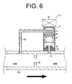
- the flow sensor 111 is provided in the tube 150 for detecting a pressure difference between the first pressure P1 and the second pressure P2 of refrigerant gas flowing through the first position 150A and the second position 150B, respectively.
- the flow sensor 111 includes a sensor body 71 and a hall device 73 as a magnetic force detecting device.
- the sensor body 71 houses a spool 75 that is movable in vertical direction.
- a moving permanent magnet 77 is fixed to the spool 75.
- a spring seat 79 is fixed to lower end of the sensor body 71 and a first spring 81 is provided between the spring seat 79 and the spool 75 for urging the spool 75 upward as viewed in the drawing.
- a second spring 83 is provided between upper inner surface of the sensor body 71 and the spool 75 for urging the spool 75 downward.
- the upstream tube 120 is connected to the sensor body 71 at a position that is higher than that of the spool 75 and the downstream tube 121 is connected to the spring seat 79, as shown in FIG. 6 .
- the spool 75 is moved upward against the urging force of the second spring 83 in the sensor body 71.
- the spool 75 is moved downward against the urging force of the first spring 81 in the sensor body 71.
- the hall device 73 is fixed to top surface of the sensor body 71.
- the hall device 73 detects the magnetic flux density that is variable in accordance with the vertical movement of the spool 75 with the moving permanent magnet 77 toward and away from the hall device 73.
- the hall device 73 is electrically connected to the control device 112 through a first control circuit 130.
- the hall device 73 generates to the control device 112 a control signal representing the detected magnetic flux density.
- the control device 112 includes a stroke computing part 113 and a voltage-frequency controlling part 114.
- the control device 112 is electrically connected to the power supply 110 through a second control circuit 131.
- the stroke computing part 113 of the control device 112 computes the present position of the piston 27 ( FIG. 1 ) based on the control signal received from the hall device 73, i.e., the flow rate of refrigerant gas flowing through the tube 150.
- the position of the piston 27 represents to the state quantity of the linear electric compressor 100.
- the state quantity of the linear electric compressor 100 can be a physical quantity influenced by the current position of the piston 27 as indicated above, a pressure or a temperature of refrigerant gas being discharged from the linear electric compressor 100 or flowing thereinto, or a combination of these state quantities.
- the physical quantity can be determined indirectly by measuring the flow rate of refrigerant gas flowing through the linear electric compressor 100 or any tube in the refrigerant circuit 200 with the aid of a flow meter.
- the physical quantity should preferably be the pressure difference between the first pressure P1 in the first position 150A and the second pressure P2 in the second position 150B that is located downstream of the first position 150A.
- the stroke computing part 113 determines the current position of the piston 27 by backward calculation of the drive frequency of the piston 27.
- the stroke computing part 113 shown in FIG. 5 generates to the voltage-frequency controlling part 114 a control signal representing the state quantity of the linear electric compressor 100.
- the voltage-frequency controlling part 114 of the control device 112 controls the voltage, the current and the current frequency of electric power supplied from the power supply 110 to the linear electric compressor 100, based on the control signal that is received from the stroke computing part 113.
- the voltage-frequency controlling part 114 can control independently the voltage, the current and the current frequency of electric power which is supplied from the power supply 110 to the linear electric compressor 100, i.e., the voltage, the current and the cycle length of current of electric power which is supplied to coils 63A, 63B, 65A, 65B.
- the same reference numerals are used for the common elements or components of the refrigerant circuit 200 and the refrigerant circuit 140 according to the first embodiment, and the description of such elements or components for the second embodiment will be omitted.
- the power supply 110 in the refrigerant circuit 200 supplies electric power to the linear electric compressor 100 based on the state quantity.
- the state quantity of the linear electric compressor 100 in the refrigerant circuit 200 is determined by detecting the physical quantity influenced by the position of the piston 27 ( FIG. 1 ) in the linear electric compressor 100.
- the electric power supplied to the linear electric compressor 100 is controlled based on the state quantity. Not only when the voltage and the current which are supplied to the coils 63A, 63B, 65A, 65B, respectively increase but also when the periodic voltage and current are kept constant, the thermal load and the pressure of refrigerant gas in the compression chamber 45 of the linear electric compressor 100 changes.
- the distance of reciprocating movement of the piston 27, i.e., the piston stroke, caused by the electromagnetic force generated by the predetermined electric power also changes.
- the first and the second pistons may collide against their corresponding valve units and the collision causes noise and vibration in the linear electric compressor 100. This may decrease the durability of the linear electric compressor 100.
- the thermal load decreases and the pressure of the refrigerant gas in the compression chamber 45 of the linear electric compressor 100 also decreases, the collision of the first and the second piston heads 31, 33 against the first and the second valve plates 15, 17, respectively, can be prevented by the refrigerant circuit 200 according to the second embodiment having the above-mentioned control based on the state quantity. Accordingly, the durability of the linear electric compressor 100 in the refrigerant circuit 200 can be also improved.
- the flow sensor 111 in the refrigerant circuit 200 can detects the pressure difference between the first pressure P1 and the second pressure P2 in the tube 150 by detecting the change of the magnetic flux density. Therefore, the flow rate of refrigerant gas flowing through the tube 150 can be detected precisely at a moderate cost.
- the flow sensor 111 which is provided in the tube 150 away from the linear electric compressor 100 is free from the influence of the magnetic flux generated by the coils 63A, 63B, 65A, 65B of the linear electric compressor 100.
- the throttle 70 is provided in the tube 150 in which high-pressure refrigerant gas flows. Therefore, pressure loss of refrigerant gas incurred in the throttle 70 does not decrease the performance of the refrigerant circuit 200.
- the other advantageous effects are the same as those in the refrigerant circuit according to the first embodiment.
- the refrigerant circuit 300 according to the third embodiment differs from the refrigerant circuit 200 of the second embodiment in that the flow sensor 111 is provided in a bend 90 of the tube 103. Accordingly, in the refrigerant circuit 300 of the third embodiment, the tube 104 that is used in the refrigerant circuit 140 of the first embodiment is used in place of the tube 150 in the refrigerant circuit 200 of the second embodiment. No throttle such as 70 is provided in the refrigerant circuit 300.
- reference symbols 130A, 130B designate first and second positions in the tube 103 of the refrigerant circuit 300 that are upstream and downstream of the bend 90, respectively, with respect to the flowing direction of refrigerant gas in the tube 103 indicated by bent arrow.
- the upstream tube 120 is connected to the first position 103A and the downstream tube 121 is connected to the second position 103B.
- the same reference numerals are used for the common elements or components of the refrigerant circuits 200 and 300 according to the second and the third embodiments, and the description of such elements or components for the third embodiment will be omitted.
- the flow sensor 111 in the refrigerant circuit 300 can detect the pressure difference between the first pressure P1 and the second pressure P2 of refrigerant gas flowing through the first position 103A and the second position 103B, respectively, based on the flow passage resistance caused by the bend 90 through which refrigerant gas flows.
- the bend 90 may not necessarily be formed by bending the tube 103 at almost a right angle.
- the bend 90 may be formed by bending the tube 103 at any angle other than a right angle. Additionally, the bend 90 may be provided at a position in which high-pressure refrigerant gas flows, e.g., at a position anywhere in the tube 104.
- the other advantageous effects are the same as those in the refrigerant circuit 200 according to the second embodiment.
- the present invention is not limited to the first through third embodiments, but may be modified within the effects of the present invention.
- the linear electric compressor 100 according to the first embodiment is used alone, but it may be used in combination with any other compressor. This is also applicable to the second and the third embodiments.
- first and the second discharge chambers 11A, 13A are formed on the first and the second end plate 11, 13 sides, respectively and a suction chamber 55 is formed in the piston 27.
- suction chambers may be formed on the first and the second end plate 11, 13 sides, respectively and a discharge chamber may be formed in the piston 27.
- the first and the second spacers 41, 43 may be made of fluororesin such as PTFE.
- the piston 27 reciprocates suitably in the first and the second cylinder bores 1A, 3A.
- the suction valve unit 50 may be of a reed type.
- any suitable sensor may be used, including a position sensor using laser or magnetic flux, a differential transformer and a proximity switch.
- a plurality of flow sensors 111 may be provided in the tubes 101-104 (150), 106.
- a pressure sensor and a temperature sensor may be used in place of the flow sensor 111.
- the stroke computing part 113 can compute the physical quantity more accurately.
- the refrigerant circuit according to the present invention may be used for a hybrid vehicle and an electric vehicle using an electric motor. It is also applicable to a vehicle equipped with an engine.
- a refrigerant circuit includes a linear electric compressor including a housing with a cylinder bore, a pair of end plates, a valve unit, a piston, an urging device for urging the piston, a coil generating electromagnetic force and a permanent magnet.
- the permanent magnet cooperates with the urging device and the coil to reciprocate the piston in the cylinder bore.
- the piston further includes a piston rod and the urging device is provided around the piston rod and a pair of piston heads integrally formed at opposite ends of the piston rod. The diameter of the piston rod is smaller than that of the piston head.
- the permanent magnet is provided on the piston head and the coil surrounds the piston head.
- the housing further includes a seat located between the pair of piston heads and the urging device is provided between the seat and each of the piston head.
Landscapes
- Engineering & Computer Science (AREA)
- Mechanical Engineering (AREA)
- General Engineering & Computer Science (AREA)
- Computer Hardware Design (AREA)
- Compressors, Vaccum Pumps And Other Relevant Systems (AREA)
- Compressor (AREA)
- Reciprocating, Oscillating Or Vibrating Motors (AREA)
Applications Claiming Priority (2)
| Application Number | Priority Date | Filing Date | Title |
|---|---|---|---|
| JP2009204288 | 2009-09-04 | ||
| JP2009283350A JP2011074910A (ja) | 2009-09-04 | 2009-12-14 | リニア電動式圧縮機及び冷凍回路 |
Publications (1)
| Publication Number | Publication Date |
|---|---|
| EP2299115A2 true EP2299115A2 (de) | 2011-03-23 |
Family
ID=43477784
Family Applications (1)
| Application Number | Title | Priority Date | Filing Date |
|---|---|---|---|
| EP10174597A Withdrawn EP2299115A2 (de) | 2009-09-04 | 2010-08-31 | Linear elektrischer Kompressor und Kühlmittelschaltung |
Country Status (3)
| Country | Link |
|---|---|
| US (1) | US20110056235A1 (de) |
| EP (1) | EP2299115A2 (de) |
| JP (1) | JP2011074910A (de) |
Cited By (3)
| Publication number | Priority date | Publication date | Assignee | Title |
|---|---|---|---|---|
| EP2699800A4 (de) * | 2011-04-18 | 2015-06-24 | Hyperspin Ltd | Fluidpumpe und verfahren zum pumpen eines fluids |
| FR3030646A1 (fr) * | 2014-12-19 | 2016-06-24 | Patrice Christian Philippe Charles Chevalier | Systeme compresseur generateur multi-etage reversible et procedes associes |
| WO2019160537A1 (en) * | 2018-02-14 | 2019-08-22 | Dresser-Rand Company | Modular linear reciprocating compressor |
Families Citing this family (18)
| Publication number | Priority date | Publication date | Assignee | Title |
|---|---|---|---|---|
| US8662029B2 (en) * | 2010-11-23 | 2014-03-04 | Etagen, Inc. | High-efficiency linear combustion engine |
| KR101065851B1 (ko) | 2011-06-01 | 2011-09-19 | 안기석 | 선형전동기를 이용한 양방향 압축기 |
| BRPI1104172A2 (pt) * | 2011-08-31 | 2015-10-13 | Whirlpool Sa | compressor linear baseado em mecanismo oscilatório ressonante |
| US8714946B2 (en) | 2012-09-13 | 2014-05-06 | General Electric Company | Linear compressor with an electro-magnetic spring |
| US9086062B2 (en) | 2012-09-13 | 2015-07-21 | General Electric Company | Linear compressor with an electro-magnetic spring |
| CN203770066U (zh) | 2013-06-28 | 2014-08-13 | Lg电子株式会社 | 线性压缩机 |
| CN103671014B (zh) * | 2013-11-21 | 2016-01-13 | 中国科学院上海技术物理研究所 | 采用短线圈径向充磁的对置式动圈直线压缩机及制造方法 |
| US20150226210A1 (en) * | 2014-02-10 | 2015-08-13 | General Electric Company | Linear compressor |
| US10502201B2 (en) * | 2015-01-28 | 2019-12-10 | Haier Us Appliance Solutions, Inc. | Method for operating a linear compressor |
| CN107762770A (zh) * | 2016-08-19 | 2018-03-06 | 青岛海尔智能技术研发有限公司 | 直线压缩机及其控制方法 |
| US10830230B2 (en) | 2017-01-04 | 2020-11-10 | Haier Us Appliance Solutions, Inc. | Method for operating a linear compressor |
| US10670008B2 (en) | 2017-08-31 | 2020-06-02 | Haier Us Appliance Solutions, Inc. | Method for detecting head crashing in a linear compressor |
| US10641263B2 (en) | 2017-08-31 | 2020-05-05 | Haier Us Appliance Solutions, Inc. | Method for operating a linear compressor |
| JP6480612B1 (ja) * | 2018-01-25 | 2019-03-13 | 日東工器株式会社 | 電磁往復動流体装置 |
| CN108462353A (zh) * | 2018-01-29 | 2018-08-28 | 广东工业大学 | 一种单缸全磁双活塞电磁发动机 |
| WO2020173480A1 (zh) * | 2019-02-28 | 2020-09-03 | 青岛海尔智能技术研发有限公司 | 一种双气缸线性压缩机和制冷设备 |
| KR102441645B1 (ko) * | 2020-08-19 | 2022-09-08 | (주)글로벌제이티에스 | 튜블러 타입 리니어 모터 |
| DE102024128320A1 (de) * | 2024-09-30 | 2026-04-02 | Viessmann Holding International GmbH | Wärmepumpe |
Citations (1)
| Publication number | Priority date | Publication date | Assignee | Title |
|---|---|---|---|---|
| JP3953735B2 (ja) | 1997-10-04 | 2007-08-08 | ズィー・アンド・ディー・リミテッド | リニアモーターコンプレッサー |
-
2009
- 2009-12-14 JP JP2009283350A patent/JP2011074910A/ja active Pending
-
2010
- 2010-08-31 EP EP10174597A patent/EP2299115A2/de not_active Withdrawn
- 2010-09-01 US US12/873,599 patent/US20110056235A1/en not_active Abandoned
Patent Citations (1)
| Publication number | Priority date | Publication date | Assignee | Title |
|---|---|---|---|---|
| JP3953735B2 (ja) | 1997-10-04 | 2007-08-08 | ズィー・アンド・ディー・リミテッド | リニアモーターコンプレッサー |
Cited By (3)
| Publication number | Priority date | Publication date | Assignee | Title |
|---|---|---|---|---|
| EP2699800A4 (de) * | 2011-04-18 | 2015-06-24 | Hyperspin Ltd | Fluidpumpe und verfahren zum pumpen eines fluids |
| FR3030646A1 (fr) * | 2014-12-19 | 2016-06-24 | Patrice Christian Philippe Charles Chevalier | Systeme compresseur generateur multi-etage reversible et procedes associes |
| WO2019160537A1 (en) * | 2018-02-14 | 2019-08-22 | Dresser-Rand Company | Modular linear reciprocating compressor |
Also Published As
| Publication number | Publication date |
|---|---|
| JP2011074910A (ja) | 2011-04-14 |
| US20110056235A1 (en) | 2011-03-10 |
Similar Documents
| Publication | Publication Date | Title |
|---|---|---|
| US20110056235A1 (en) | Linear electric compressor and refrigerant circuit | |
| CN100432430C (zh) | 往复式压缩机 | |
| US6676388B2 (en) | Gas compression apparatus for reciprocating compressor | |
| US6220393B1 (en) | Oil supply apparatus for linear compressor | |
| KR100544161B1 (ko) | 가변용량형 압축기용 제어밸브 | |
| KR20060009708A (ko) | 왕복동식 압축기 | |
| CN103375381A (zh) | 可变容量压缩机用控制阀 | |
| KR100856845B1 (ko) | 선형 모터 및 이 선형 모터를 포함하는 선형 압축기 | |
| EP1483504A1 (de) | Aufbauanordnung für einen resonierenden verdichter | |
| WO2018070281A1 (ja) | リニア圧縮機及びこれを搭載した機器 | |
| KR101484325B1 (ko) | 리니어 압축기 | |
| JP2017211137A (ja) | 電気式膨張弁 | |
| CN105041630A (zh) | 一种变排量压缩机用电磁控制阀 | |
| US7108490B2 (en) | Reciprocating compressor having anti-collision means | |
| US20080226477A1 (en) | Electromagnetic oscillating fluid pump | |
| WO2006025620A1 (en) | Linear compressor | |
| JP2011052648A (ja) | リニア電動式圧縮機 | |
| US20130115113A1 (en) | Reciprocating compressor | |
| WO2011027700A1 (ja) | リニア電動式圧縮機 | |
| WO2019017028A1 (ja) | 往復動式リニアモータ | |
| JP2011144988A (ja) | 冷凍回路 | |
| KR20030091798A (ko) | 제어밸브 | |
| JPH09292050A (ja) | 四方弁 | |
| KR101796038B1 (ko) | 가변 용량 압축기용 전자제어밸브 | |
| JPH10115473A (ja) | リニアコンプレッサ |
Legal Events
| Date | Code | Title | Description |
|---|---|---|---|
| PUAI | Public reference made under article 153(3) epc to a published international application that has entered the european phase |
Free format text: ORIGINAL CODE: 0009012 |
|
| 17P | Request for examination filed |
Effective date: 20100831 |
|
| AK | Designated contracting states |
Kind code of ref document: A2 Designated state(s): AL AT BE BG CH CY CZ DE DK EE ES FI FR GB GR HR HU IE IS IT LI LT LU LV MC MK MT NL NO PL PT RO SE SI SK SM TR |
|
| AX | Request for extension of the european patent |
Extension state: BA ME RS |
|
| STAA | Information on the status of an ep patent application or granted ep patent |
Free format text: STATUS: THE APPLICATION HAS BEEN WITHDRAWN |
|
| 18W | Application withdrawn |
Effective date: 20120118 |