EP2297884B1 - Procédé et appareil de détection de trame dans un système de communication - Google Patents
Procédé et appareil de détection de trame dans un système de communication Download PDFInfo
- Publication number
- EP2297884B1 EP2297884B1 EP09798462.9A EP09798462A EP2297884B1 EP 2297884 B1 EP2297884 B1 EP 2297884B1 EP 09798462 A EP09798462 A EP 09798462A EP 2297884 B1 EP2297884 B1 EP 2297884B1
- Authority
- EP
- European Patent Office
- Prior art keywords
- time
- reference signal
- subframe
- correlation
- signal
- Prior art date
- Legal status (The legal status is an assumption and is not a legal conclusion. Google has not performed a legal analysis and makes no representation as to the accuracy of the status listed.)
- Active
Links
- 230000006854 communication Effects 0.000 title claims description 40
- 238000004891 communication Methods 0.000 title claims description 40
- 238000000034 method Methods 0.000 title claims description 37
- 238000001514 detection method Methods 0.000 title description 4
- 230000005540 biological transmission Effects 0.000 claims description 27
- 239000002131 composite material Substances 0.000 claims description 17
- 238000012545 processing Methods 0.000 claims description 16
- 230000001902 propagating effect Effects 0.000 claims 1
- 230000002596 correlated effect Effects 0.000 description 7
- 238000005259 measurement Methods 0.000 description 7
- 238000010586 diagram Methods 0.000 description 4
- 230000008878 coupling Effects 0.000 description 3
- 238000010168 coupling process Methods 0.000 description 3
- 238000005859 coupling reaction Methods 0.000 description 3
- 238000011144 upstream manufacturing Methods 0.000 description 3
- 230000002238 attenuated effect Effects 0.000 description 2
- 230000007175 bidirectional communication Effects 0.000 description 2
- 230000000875 corresponding effect Effects 0.000 description 2
- 238000012986 modification Methods 0.000 description 2
- 230000004048 modification Effects 0.000 description 2
- 241000238876 Acari Species 0.000 description 1
- 230000001413 cellular effect Effects 0.000 description 1
- 230000001427 coherent effect Effects 0.000 description 1
- 230000003247 decreasing effect Effects 0.000 description 1
- 230000000694 effects Effects 0.000 description 1
- 238000013442 quality metrics Methods 0.000 description 1
- 238000000926 separation method Methods 0.000 description 1
- 230000003068 static effect Effects 0.000 description 1
- 238000006467 substitution reaction Methods 0.000 description 1
- 230000001360 synchronised effect Effects 0.000 description 1
Images


Classifications
-
- H—ELECTRICITY
- H04—ELECTRIC COMMUNICATION TECHNIQUE
- H04L—TRANSMISSION OF DIGITAL INFORMATION, e.g. TELEGRAPHIC COMMUNICATION
- H04L5/00—Arrangements affording multiple use of the transmission path
- H04L5/14—Two-way operation using the same type of signal, i.e. duplex
- H04L5/1469—Two-way operation using the same type of signal, i.e. duplex using time-sharing
-
- H—ELECTRICITY
- H04—ELECTRIC COMMUNICATION TECHNIQUE
- H04J—MULTIPLEX COMMUNICATION
- H04J3/00—Time-division multiplex systems
- H04J3/02—Details
- H04J3/06—Synchronising arrangements
- H04J3/0602—Systems characterised by the synchronising information used
- H04J3/0605—Special codes used as synchronising signal
- H04J3/0608—Detectors therefor, e.g. correlators, state machines
-
- H—ELECTRICITY
- H04—ELECTRIC COMMUNICATION TECHNIQUE
- H04L—TRANSMISSION OF DIGITAL INFORMATION, e.g. TELEGRAPHIC COMMUNICATION
- H04L27/00—Modulated-carrier systems
- H04L27/26—Systems using multi-frequency codes
- H04L27/2601—Multicarrier modulation systems
- H04L27/2647—Arrangements specific to the receiver only
- H04L27/2655—Synchronisation arrangements
- H04L27/2656—Frame synchronisation, e.g. packet synchronisation, time division duplex [TDD] switching point detection or subframe synchronisation
-
- H—ELECTRICITY
- H04—ELECTRIC COMMUNICATION TECHNIQUE
- H04W—WIRELESS COMMUNICATION NETWORKS
- H04W56/00—Synchronisation arrangements
- H04W56/0055—Synchronisation arrangements determining timing error of reception due to propagation delay
- H04W56/0065—Synchronisation arrangements determining timing error of reception due to propagation delay using measurement of signal travel time
- H04W56/007—Open loop measurement
- H04W56/0075—Open loop measurement based on arrival time vs. expected arrival time
- H04W56/008—Open loop measurement based on arrival time vs. expected arrival time detecting arrival of signal based on received raw signal
Definitions
- Embodiments of the invention relate to a method of determining a boundary of a transmission structure in a time-division duplexing 'TDD' structure, an apparatus for switching a TDD system, and a communications network including such apparatus.
- Time-Division Duplexing (TDD) system must be coordinated to switch between uplink and downlink communication at the proper times to enable a properly functioning TDD system.
- a host unit coordinates the switching times and the host unit transmits information to wireless terminals regarding the switching times.
- the wireless terminals use the information to determine when to switch, such that communications from the wireless terminals do not collide with communications from the host unit.
- equipment within the communication network that relays/transmits information between the host unit and the wireless terminal may also need to switch between uplink and downlink communications.
- this network equipment does not have the circuitry required to properly receive, filter, and decode the information signals from the host unit regarding when to switch between upstream and downstream communication.
- US2007/0201402 is directed to a method and system for generating a switching timing signal for separating a transmitting and receiving signal in an RF repeater for a mobile telecommunication network using TDD and OFDM modulation.
- a method of determining a boundary of a subframe in a time division duplexing (TDD) system detects a power level of a signal on at least one radio frequency, the signal comprising at least one subframe.
- a time-domain correlation is done on the detected signal with a first reference signal, wherein the first reference signal represents at least one subframe.
- the location in time of a boundary of the at least one subframe of the detected signal is determined based on the correlation of the detected signal and the first reference signal.
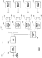
- FIG. 1 is a block diagram of one embodiment of a communication network 100.
- communication network 100 comprises a base station 102 which is communicatively coupled to a distributed antenna system (DAS) 103.
- DAS 103 is used to transport radio frequency signals between one or more upstream devices (for example, base station transceiver 102, wireless access points, or other sources of radio frequency signals) and one or more downstream wireless devices (for example, wireless terminals 112).
- base station transceiver 102 also referred to herein as "base station” 102
- base station 102 is a part of a telecommunication-service providers' infrastructure and wireless terminals 112 comprise customer premise equipment.
- an original downlink radio frequency signal is originally transmitted by base station 102 for reception by one or more wireless terminals 112 and an original uplink radio frequency signal is originally transmitted by a wireless terminal 112 for reception by base station 102.
- Base station 102 manages communication among wireless terminals 112, and between wireless terminals 112 and other communication networks (not shown) that are coupled to base station 102.
- base station 102 manages communication between wireless terminals 112 and a public switched telephone network (PSTN).
- PSTN public switched telephone network
- communication network 100 is a cellular/PCS system and base station 102 communicates with a base station controller which acts as a voice/PSTN gateway to the PSTN.
- base station 102 manages communication between wireless terminals 112 and an internet protocol (IP)-based network (such as the internet) via communication with an IP gateway.
- IP internet protocol
- base station 102 performs baseband processing on IP data from an IP gateway and places the IP data onto a channel.
- base station 102 is an IEEE 802.16 compliant base station.
- base station 102 may also meet the requirements of WiMax, WiBro, LTE, or other consortium.
- base station 102 comprises multiple functionalities including managing communications between both a PSTN and an IP-based network.
- DAS 103 comprises a hub 106 communicatively coupled to base station 102, and three remote antenna units 108-111 located remotely from and communicatively coupled to hub 106.
- Each remote antenna unit 108-111 includes one or more antennas 104 which are used to communicate wirelessly with wireless terminals 112.
- hub 106 is optically coupled to base station 102, although in other embodiments, hub 106 and base station 102 are communicatively coupled by coaxial cables, wireless antennas, or other communication medium.
- hub 106 is optically coupled to each remote antenna unit 108-111, although in other embodiments, hub 106 and remote antenna units 108-111 are communicatively coupled by coaxial cables, wireless antennas, or other communication medium.
- each of remote antenna units 108-111 includes two antennas 104, a primary antenna and a diversity antenna; although in other embodiments only a single antenna 104 or more than two antennas 104 are used at each remote antenna unit 108-111.
- DAS 103 also includes one or more expansion units 114 that are communicatively coupled between hub 106 and remote antenna units 110, 111 to, for example, provide coverage for each floor of a multi-floor building.
- Base station 102 uses DAS 103 to communicate with wireless terminals 112 via antennas 104. Bidirectional communication between base station 102 and the plurality of wireless terminals 112 is accomplished through use of a multiple access scheme.
- base station 102 and wireless terminals 112 communicate using a code-division multiple access (CDMA) scheme.
- base station 102 and wireless terminals 112 communicate using an orthogonal frequency division multiple access (OFDMA) scheme.
- CDMA code-division multiple access
- OFDMA orthogonal frequency division multiple access
- other multiple access schemes are used (e.g. TDMA, FDMA), or more than one multiple access scheme is used including, for example, CDMA for voice communications and OFDMA for data communications.
- some or all communications between base station 102 and wireless terminals 112 use a time division duplex (TDD) communication scheme.
- TDD schemes enable bi-directional communication between two devices by having uplink transmissions (from wireless terminal 112 toward base station 102) and downlink transmissions (from base station 102 toward wireless terminal 112) occur at different times.
- both uplink and downlink communications share the same frequencies.
- System 100 enables communication between wireless terminals 112 and one or more other devices which are communicatively coupled to base station via, for example, a PSTN or internet based network.
- Wireless terminals 112 transmit/receive signals to/from remote antenna units 108-111 via remote antennas 104.
- wireless terminals 112 each communicate with one remote antenna unit 108-111 at a time, except for during certain situations, for example during handoffs. For example, information which is outgoing from a wireless terminal 112 is transmitted by the wireless terminal 112 and received at, for example, remote antenna unit 108 which is communicating with the transmitting wireless terminal 112.
- Remote antenna unit 108 reproduces the signal received from wireless terminal 112 and sends the signal along with other signals received from other wireless terminals 112 transmitting to remote antenna unit 104 to hub 106.
- Hub 106 receives information from remote antenna unit 108 (and other remote antenna units 109-111, some through expansion unit 114) reproduces the signals received and sends the signals to base station 102.
- Base station 102 processes the information and transmits the information toward its destination. Incoming information from another network is received by base station 102.
- Base station 102 determines which of wireless terminals 112 is the destination of the information, generates, modulates, and transmits a signal containing the information to hub 106.
- Hub 106 receives the signal, reproduces the signal, and sends the signal to, for example, remote antenna unit 108 which is in communication with the destination wireless terminal 112.
- Remote antenna unit 108 receives the signal from hub 106, reproduces the signal, and sends the signal wirelessly to wireless terminal 112, where in the information is received and processed.
- hub 106 and remote antenna units 108-111 do not demodulate or unpack the signals transmitted by base station 102 and wireless terminals 112. Instead hub 106 and remote antenna units 108-111 act as relays, receiving and reproducing the signals received while performing only minimal processing on the signals.
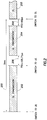
- FIG. 2 illustrates one example of a TDD transmission structure 200.
- transmission structure 200 comprises a frame (also referred to herein at "frame" 200) having a downlink (DL) subframe 202 followed by an uplink (UL) subframe 204. A portion of a second downlink subframe 205 of a subsequent TDD frame is also shown. Each start or end of a transmission is referred to herein as a transmission boundary.
- each TDD frame 200 is substantially similar in structure having a 5ms fixed duration and containing one downlink subframe followed by one uplink subframe. In some embodiments, a portion of TDD frame 200 is allocated for control data.
- TDD frame 200 may have a variable duration, and/or multiple uplink or downlink subframes may be included within each frame 200. Additionally, other embodiments may have an uplink subframe first which is followed by a downlink subframe, or a variation across frames between uplink and downlink subframes starting each frame.
- TDD frame 200 The beginning portion of TDD frame 200 is allocated to downlink subframe 202.
- a time gap (TTG) 206 occurs before the start of uplink subframe 204.
- uplink subframe 204 begins, and another time gap (RTG) 208 occurs between the end of uplink subframe 204 and the beginning of the subsequent downlink subframe 205 of the next frame.
- base station 102 is transmitting to one or more of wireless terminals 112.
- uplink subframe 204 one or more of wireless terminals 112 are transmitting to base station 102.
- TTG 206 between downlink subframe 202 and uplink subframe 204 allows time for base station 102 to switch from transmit to receive mode and for each wireless terminal 112 to switch from receive to transmit mode.
- RTG 208 allows time for base station 102 to switch from receive to transmit mode and wireless terminals 112 to switch from transmit to receive mode.
- TTG 206 and RTG 208 also allow time margin for such things as base station/mobile synchronization and propagation delay determination/adjustment.
- the RF circuitry within DAS 103 also switches between processing downlink transmissions and uplink transmissions. Similar to base station 102 and wireless terminals 112, the switching of the RF circuitry within DAS 103 occurs during time gaps TTG 206 and RTG 208.
- the RF circuitry within hub 106 as well as RF circuitry within each remote antenna unit 108-111 performs the uplink and downlink switching.
- each frame 200 has the same duty cycle, such that the duration of downlink subframe 202 and uplink subframe 204 are fixed.
- the duty cycle is variable such that the duration of downlink subframe 202 and uplink subframe 204 are variable on a frame-by-frame basis.
- the subframe durations are dynamically assigned during transmission based on system traffic, user preferences, or other parameters.
- frame 200 has 47 total frames and has predetermined downlink subframe lengths of 35, 34, and 33 symbols, and uplink subframe lengths of 12, 13, and 14 symbols as allowed by the communications protocol.
- a 35 symbol downlink subframe 202 corresponds to a 12 symbol uplink subframe 204.
- the total number of uplink and downlink symbols remains at 47. Thus, if there are fewer symbols in a downlink subframe 202, there will be more symbols in the corresponding uplink subframe 204.
- the time periods for TTG 206 and RTG 208 have a fixed duration.
- the communication structure used by system 100 is a frame which comprises two subframes as illustrated in Figure 2 , it should be understood that the scope of the present disclose is intended to include other frame/subframe structures and other communication structures as known to those skilled in the art.
- Wireless terminals 112 obtain the timing of downlink subframe 202 and uplink subframe 204 from communications sent by base station 102. In one embodiment, these communications occur on a separate control channel and wireless terminals 112 listen to the control channel to obtain the frame and subframe timing. In another embodiment, wireless terminals 112 obtain the frame and subframe timing from messages sent by base station 102 within frame 200 or by listening to current transmissions on the payload channel and ascertaining the timing directly from the transmissions. In any case, wireless terminals 112 determine at what time of each frame 200 begins, when downlink subframe 202 will end, when to switch from receiving mode to transmitting mode, and at what point to start transmitting uplink subframe 204.
- hub 106 and remote antenna units 108-111 do not have the circuitry required to demodulate and unpack signals transmitted between base station 102 and wireless terminals 112.
- hub 106 and remote antenna units 108-111 have circuitry included for independently determining the timing of the frames and subframes.
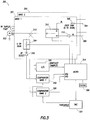
- Figure 3 illustrates one embodiment of a circuit 300 for determining the location in time of a boundary of a transmission structure in communications network 100.
- circuit 300 determines a timing of a subframe boundary (subframe timing) based on the power level of signals that are transmitted within network 100. Based on the determined subframe timing, circuit 300 determines when to switch between downlink and uplink transmission. For example, in this embodiment, circuit 300 determines the location in time of the starting boundary for downlink subframe 202. In this embodiment, determining the starting time of downlink subframe 202 also determines the start time of frame 200, because the start of downlink subframe 202 coincides with the start of frame 200. Circuit 300 then determines when to switch from uplink transmission to downlink transmission based on the determined starting boundary of downlink subframe 202.
- Circuit 300 detects signals currently being transmitted on network 100 (for example, between base station 102 and other wireless terminals not shown) and compares the power level of the detected signals with a known reference signal to determine the timing of a subframe boundary.
- the comparison is a correlation with a reference signal which comprises a signal having a power level matching an expected power level and duration of a received downlink subframe. More detail regarding the correlation process is provided below.
- circuit 300 uses the determined timing of the start of a detected frame to predict the start of subsequent frames. Circuit 300 then determines when to set switch 312 to relay downlink transmission based on the predicted start time of the upcoming frame.
- circuit 300 is set to downlink mode to relay downlink transmissions from base station 102 to wireless terminals 112 in accordance with the frame and subframe timing of network 100.
- the apparatuses and methods described herein can be used to determine the frame and/or subframe timing of a system as desired.
- the start of uplink subframe 204 is also predicted from the determined timing of the start of a frame. For example, when the frame duty cycle is fixed, the start of uplink subframe 204 is fixed relative to start of frame 200. Once the location in time of the start of a frame is determined, the start of subsequent frames as well as the start of the uplink subframes within those frames is predicted based on the known frame duration and the known time between the start of frame and the start of the uplink subframe within that frame.
- the frame duty cycle is variable, and the start of uplink subframe 204, varies across frames based on the duty cycle of each particular frame.
- frame timing is determined as described above, and the start of downlink subframe 202 is thus known because the start of downlink subframe 202 coincides with the start of frame 200.
- the start of uplink subframe 202 is determined by detecting the falling edge of downlink subframe 202 in real-time and switching from downlink mode to uplink mode based on the detected falling edge. More detail regarding real-time switching based on a falling edge of a subframe is provided in United States Patent Application Serial No. 12/144,977 titled "METHOD AND APPARATUS FOR SWITCHING IN A TDD SYSTEM".
- both hub 106 and remote antenna units 108-111 comprise circuits such as circuit 300 to determine when to switch between uplink and downlink transmission modes.
- circuit 300 is included only within hub 106.
- hub 106 determines the switching times for itself, as well as remote antenna units 108-111, and forwards control signals indicating the time for switching to remote antenna units 108-111 as described in United States Patent Application Serial No. 12/144,939 , entitled "SYSTEM AND METHOD FOR SYNCHRONIZED TIME-DIVISION DUPLEX SIGNAL SWITCHING".
- circuit 300 processes the signals of two frequency bands.
- Circuit 301 processes signals of a first frequency band and circuit 302 processes signals of a second frequency band.
- circuit 301 and 302 are similar, with the exception of minor differences to enable each circuit 301,302 to support its respective frequencies. Thus, only circuit 301 is described in detail. In other embodiments, only one frequency band is supported. In still other embodiments, more than two frequency bands are supported.
- signals are transmitted and received to/from base station 102 at RF duplex port 303.
- Signals to/from wireless terminals 112 are transmitted and received at downlink (DL) port 304 and uplink (UL) port 306 respectively.
- Downlink port 304 and uplink port 306 are coupled to one or more antennas 104 which transmit and receive wireless signals from wireless terminals 112.
- a variable resistor 308 controls the power of downlink signals transmitted from downlink port 304.
- an amplifier 310 amplifies signals received from wireless terminals 112 for further processing and transmission to base station 102.
- a switch 312 switches circuit 300 between uplink transmission (uplink mode) and downlink transmission (downlink mode) by coupling RF duplex port 303 to either downlink port 304 or uplink port 306.
- switch 312 is a single pole, double throw switch having one common connection (coupled to duplex port 303) and two switched connections (coupled to downlink port 304 and uplink port 306 respectively).
- port 303 comprises two simplex ports which operate as a duplex port. More detail regarding the configuration of circuit 300 and port 303 as simplex or duplex is provided in United States Patent Application Serial No. 12/144,913 , entitled "SYSTEM AND METHOD FOR CONFIGURABLE TIME-DIVISION DUPLEX INTERFACE".
- FIG. 4 one embodiment of a method 400 for determining the subframe timing of a signal is disclosed.
- the following discussion relates to determining the timing of downlink subframe 202, however, it should be understood that the methods and apparatus described herein could also be used with appropriate adjustments and modifications to determine the timing of uplink subframe 204.
- Method 400 begins at block 402 where the power level of a downlink signal is detected.
- the detected signal is correlated with a reference signal and, at block 406, the location in time of a boundary of a subframe in the detected downlink signal is determined from the correlation.
- the start time of subsequent downlink subframes are predicted based on the determined start time of the detected downlink subframe.
- switch 312 is set to downlink mode in time for the start of an upcoming downlink subframe.
- RF detector 316 is a root-mean-squared (RMS) detector. Prior to the downlink signal reaching RF detector 316, the signal is attenuated by attenuator 324 if necessary. More detail regarding attenuator 324 is provided below.
- RF detector 316 measures the power of the downlink signal, and an analog to digital (A/D) converter 320 reads the power level measured by RF detector 316.
- A/D analog to digital
- A/D converter 320 converts the power level from RF detector 316 into digitized samples ("snapshot samples") for microprocessor 314.
- Microprocessor 314 records the time in which each sample was collected and collects samples for a period of time such that an entire downlink subframe 202 is detected. In one embodiment, the samples are collected for a minimum of slightly more than one frame period based on the number of samples in the reference signal. In one embodiment, to reduce the chance of an uplink subframe being coupled into RF detector 316, switch 312 remains in the downlink position throughout the detection by RF detector 316.
- microprocessor 314 correlates the detected samples with a reference signal.
- the reference signal is a representation of a valid downlink subframe 202.
- the reference signal is a representation of a detected downlink subframe 202 comprising a number of symbols that is a valid subframe length.
- microprocessor 314 determines the start of downlink subframe 202 based on the results of the correlation between the detected samples and the reference signal.
- the correlation is a time-domain correlation that compares the reference signal to the detected samples by overlapping the detected samples and the reference signal, multiplying each detected sample by the value that is overlapped in the reference signal.
- the correlation result for this first point in time is then computed by summing all the products of the multiplication together.
- the reference signal is then time shifted relative to the received samples, and the multiplication and summation is repeated to obtain a correlation result for this second point in time. This process is repeated to obtain time varied correlations between the reference signal and the detected samples.
- microprocessor 314 determines the frame timing from the correlation results. For example, in one embodiment where system 100 uses a fixed duty cycle frame, the correlation at block 404 between the reference signal and the detected samples results in a correlation peak at a single point in time. The correlation peak occurs where the reference signal and the received samples align in time. A single correlation peak occurs because the subframe length of the detected subframe is the same as the subframe length of the reference signal. Since the subframe length in a fixed duty cycle system is fixed and known, the reference signal is made to represent a subframe having the same length as the subframes used by the system. Thus, there is one point in time at which the reference signal and the detected signal align. At block 406, microprocessor 314 determines the start time of the received downlink subframe based on the knowledge of the time in which the samples were detected, and the determination of the point in time at which the detected samples were aligned with the reference signal.
- system 100 uses frames having variable duty cycles.
- the correlation of block 404 may result in a correlation plateau where multiple points in time are tied for the highest correlation. This is because the subframe length of the detected subframe is unknown, and therefore, the reference signal may not match the length of the detected subframe.
- the detected subframe has a different length than the subframe of the reference signal there is not a single correlation peak when correlating with a reference signal as described with respect to fixed duty cycle frames above.
- the reference signal is correlated with both the maximum subframe length expected to be detected and the minimum subframe length expected to be detected.
- the maximum and minimum expected subframe lengths are the maximum and minimum valid subframe lengths allowed by the communication protocol.
- the detected samples are correlated with both the maximum subframe length and the minimum subframe length, by performing two correlations.
- One correlation is with a first reference signal having the longest subframe length and a second correlation is with a second reference signal having the shortest subframe length.
- the start of the downlink subframe in the first reference signal is aligned with the start of downlink subframe in the second reference signal and then the first and second reference signals are correlated with the detected signal.
- the correlation is a time-domain correlation where the detected signal is correlated against a reference signal at a first point in time and then time shifted and re-correlated at the second point in time, as so on.
- microprocessor 314 determines the start of the downlink subframe based on the composite correlation results.
- a single correlation is performed which includes both the maximum expected subframe length and the minimum expected subframe length.
- a single composite reference signal is created by adding the first reference signal and the second reference signal together and the detected signal is correlated with the composite reference signal. Then, at block 406, microprocessor 314 determines the start time of the received downlink subframe based on the correlation.
- correlation is performed over a plurality of downlink subframes 202.
- a plurality of downlink subframes 202 are detected by RF detector 316, sampled by A/D converter 320, and sent to microprocessor 314.
- Microprocessor 314 performs correlation of each downlink subframe with the reference signal(s) as described above, or correlates the downlink subframes with a lengthened reference signal comprising the number of downlink subframes detected. Since multiple subframes are correlated, multiple correlation peaks result (one peak per downlink subframe).
- the time value is extracted from each peak, and the peak time values for each frame are sorted.
- the median peak time value is selected as the start of downlink subframe.
- the correlation results for each frame are added coherently, to produce composite correlation results having a single peak and a length of one frame.
- coherent summation means that point 1 of frame 1 is added to point 1 of frame 2 and point 2 of frame 1 is added to point 2 of frame 2, and so on.
- the time value is then extracted from the single composite peak.
- an initial estimate of the peak location is made prior to coherently summing the correlation results for the frames, and the peak of each frame is moved to the center of the frame prior to summation.
- the initial estimate of the peak location is made by extracting the time value from each peak, sorting the peak time values, and choosing the median value of the sorted values as describer in the previous paragraph.
- a window is used to narrow the range of time over which the correlation is performed.
- the timing information is estimated and subsequent correlations are performed over smaller window of time. This can reduce the processing power required to perform the correlation.
- correlation is initially performed for a window of one frame length. After three correlations are performed, the timing information relating to the peak from the previous correlations is used to estimate the peak location of subsequent frames. Correlations performed on the subsequent frames are performed over a window having a length of 5% of the frame length.
- the reduced window size is determined based on the amount of drift experienced to reduce the likelihood of missing the peak of the frame being sampled with the reduced window.
- the window size and sample rate are variable and are dynamically updated based on system parameters (for example, the current drift calculation) as correlations are performed over time. More detail regarding the determination of drift is provided below.
- the start time of subsequent downlink subframes is predicted at block 408 based on the duration of each frame. For example, if the start of the received downlink subframe is determined to be at time 104 of clock 328, and 25,000 ticks of clock 328 is equal to the duration of one frame, the start of the frame immediately subsequent to the frame detected (and thus the start of the subsequent frame's downlink subframe) is at time 25,104 of clock 328. In this way, clock 328 is used to maintain the frame timing for circuit 300.
- microprocessor 314 uses the timing information to set switch 312 to downlink mode (coupling signals from RF duplex port 303 to downlink port 304) in time for the start of downlink subframe 202.
- the timing information is used to discipline the phase of clock 328 such that switch 312 is set to downlink mode in time for the start of downlink subframe 202.
- the timing information is used to adjust a counter within microprocessor 314 that is used to determine the start of a downlink subframe. For example, a counter within microprocessor 314 continuously counts down, and is set to a value at the start of each frame such that the counter reaches zero when it is time to set switch 312 to downlink mode for the start of the next frame. Once the counter reaches zero, the counter is reloaded with the same value.
- circuit 300 determines the end of uplink subframe 204 by detecting uplink signals and correlating the detected signals with an uplink reference signal.
- Time drift occurs, for example, because of differences between the frequency of clock 328 and the frequency of the received signal.
- measurements of the frame/subframe timing are made and adjustments to circuit 300 are made if necessary.
- Method 500 begins by detecting the downlink signal (502), correlating the downlink signal with a reference signal (504), and determining the location in time of a boundary of a subframe in the downlink signal (506).
- Blocks 502, 504, and 506 of Figure 5 are similar to blocks 402, 404, and 406 of Figure 4 , and are not re-described herein in detail.
- microprocessor 314, at block 508, compares the determined frame boundary with a subsequent frame boundary (for example, as determined by method 400) to determine a difference between the predicted frame boundary and the determine frame boundary. In one embodiment, the comparison at block 508 first determines a first time offset for the earlier frame. A second time offset is also determined for the subsequent frame.
- the time offsets are the determined from a single reference point in time. Thus, the two offsets can be compared to determine the difference in time between the earlier subframe boundary and the subsequent subframe boundary.
- the difference between the subsequent frame boundary and the earlier frame boundary along with the duration of time since the frame detection of the subsequent frame boundary determination is used to determine the time drift.
- the number of frames between the earlier subframe and the subsequent subframe are determined, and the difference between the earlier frame and the subsequent frame is divided by the number of frames to determine the drift across those frames.
- microprocessor 314 adjusts the time that switch 312 is set to incorporate the time drift.
- time drift is measured by re-determining the frame timing after the counter for microprocessor 314 is initially set for the frame timing as discussed with respect to method 400.
- the re-determined frame timing is then used to determine a difference between the re-determined frame timing and the counter predicted frame timing. This difference along with the amount of time since the counter was set is used to adjust the counter to account for time drift.
- the counter is adjusted such that the value stored in counter is one count higher than normal every twenty frames to account for the 1 ⁇ 2 tick error in the counter.
- the phase of clock 328 is adjusted in a similar manner to account for time drift.
- the frequency of clock 328 is adjusted based on the measured time drift, such that the frequency of clock 328 is closer to the frequency of the received signals.
- the time drift is measured periodically during the operation of circuit 300, and the counter or clock 328 are updated as needed to account for changes in the time drift.
- the duration between time drift measurements is set based on the accuracy of the frequency of clock 328 to the signal frequency. Thus, the larger the frequency difference between clock and the transmitted signals, the shorter the duration is between time drift measurements.
- the time drift is measured from the same set of samples as the initial frame timing determination of method 400.
- blocks 508, 510, and 512 are performed after blocks 402, 404, 406 and 408 and either before, after, or with block 410. In fact, in one embodiment, only one adjustment is made to the counter or clock 328 such that block 512 and 410 are included as the same step.
- samples are taken across multiple frames. The samples are split into two sections. The first section is used as a reference for determining the initial frame timing as discussed with respect to method 400. Then, the time drift is calculated using the second section as discussed with respect to method 500. In one embodiment, if the counter is not updated immediately after the initial frame timing determination, the amount of time that has elapsed during the second section and the time at which the counter is actually updated is also factored in to the counter setting.
- the drift calculations are averaged over a number of calculations to determine the adjustment needed. This reduces the effect of short term variations in the signals and clock.
- the drift calculations are ignored if the calculations are determined to be erroneous.
- signals may not be present at a time in which a drift measurement is calculated (for example, bad weather, disconnection of equipment, and others).
- Drift calculations taken during a time in which no signal is present may result in erroneous measurements, because the drift calculation will be based on noise and not an actual detected subframe.
- each drift calculation must be above a threshold quality level.
- each correlation result is normalized by dividing the correlation peak by the average power of the detected signal. This results in a quality metric for the detected signal. This normalized peak is then compared to a threshold of quality.
- the threshold is selected as 0.7. If the normalized peak is above the threshold, then the drift calculation from that peak is used. If, however, the normalized peak is equal to or below the threshold, then the drift calculation is discarded.
- Attenuator 324 reduces the dynamic range required of A/D converter 320 by attenuating the power level of high powered signals, prior to the signals reaching A/D converter 320.
- Microprocessor 314 controls attenuator 324 based on the power level of signals read by RF detector 316 and A/D converter 320. For example, in this embodiment, the signal range requirements at downlink port 304 are 25 dB. Since RF detection occurs before switch 312, the signal range seen at coupler 315 is an additional 20 dB.
- the signal range seen at coupler 315 is approximately 45 dB.
- Attenuator 324 has an attenuation of 20 dB when enabled and 0 dB when disabled.
- microprocessor 314 enables attenuator 324 to reduce the signal levels at RF detector 316 and A/D converter 320 by 20 dB.
- microprocessor 314 determines whether to enable attenuator 324 prior to analyzing the downlink signal to determine the frame/subframe timing as described in methods 400 and 500. To protect RF detector 316 and A/D convert 320, microprocessor 314 initially enables attenuator 324 prior to coupler 315 coupling any signals to attenuator 324, RF detector 316, or A/D converter 320. Microprocessor 314 then determines whether to disable attenuator 324 based on the power level of the signals received. Once attenuator 324 is enabled, A/D converter 320 samples the downlink signal over a number of frames.
- Microprocessor 314 then receives the power level from A/D converter 320 and compares the power level to an attenuator threshold. If the average power level is below the attenuator threshold, microprocessor 314 disables attenuator 324. If the average power level is equal to or above the attenuator threshold, attenuator 324 remains enabled.
- microprocessor 314 sums the power level of all samples within a fixed number of frames to determine whether to enable/disable the attenuator.
- the summation value is compared to the threshold which corresponds to an input signal level of between 0 and -5 dBm at RF detector 316. Since microprocessor 314 sums the power level of all the samples, the frame duty cycle factors in to how large the summation value is. In other words, a -25 dBm signal, for example, has two different summation values depending on the duty cycle of the frame.
- the summation value is normalized by the length of the downlink subframe.
- the length of the downlink subframe is not known or varies over the frames, thus in one embodiment, the threshold power level is normalized by both the longest expected downlink subframe and the shortest expected downlink subframe.
- the threshold of attenuator 324 is chosen as the expected power level of a sampled downlink subframe taking into account the downlink subframe length. In another embodiment, for variable duty cycle frames, the threshold is chosen as the average expected power level of a sampled downlink subframe with each sample in the frame summed together. The average is the expected power level between the maximum and minimum downlink subframe lengths.
- Attenuator 324 When attenuator 324 is disabled, attenuator 324 is re-enabled when the power level of signals rises to a threshold.
- the threshold for re-enabling attenuator 324 is the same as the threshold for disabling as discussed above.
- the threshold for re-enabling attenuator 324 is slightly higher than the threshold for disabling attenuator 324 in order to have hysterisis. In one embodiment, there is a 9 dB separation between the two thresholds to ensure hysterisis and compensate for the error in the measured power level for variable duty cycle frames.
Claims (16)
- Procédé (400) de détermination d'une limite d'une structure de transmission dans un système de duplexage par répartition dans le temps, « TDD », comprenant les étapes ci-dessous consistant à :détecter (402) un niveau de puissance d'un signal sur au moins une fréquence radio, le signal comportant au moins une sous-trame ;corréler dans le domaine temporel (404) le signal détecté avec un premier signal de référence connu prédéterminé et un second signal de référence connu prédéterminé, dans lequel le premier signal de référence est associé à une longueur de sous-trame maximale qui devrait être détectée et le second signal de référence est associé à une longueur de sous-trame minimale qui devrait être détectée ; etdéterminer (406, 408) un emplacement dans le temps d'une limite de ladite au moins une sous-trame du signal détecté, sur la base de la corrélation du signal détecté avec le premier signal de référence et le second signal de référence.
- Procédé (400) selon la revendication 1, dans lequel l'étape de corrélation dans le domaine temporel (404) du signal détecté avec un premier signal de référence connu prédéterminé et un second signal de référence connu prédéterminé comprend en outre les étapes ci-dessous consistant à :corréler, dans le domaine temporel, le signal détecté, avec le premier signal de référence, en vue de produire une première corrélation ;corréler, dans le domaine temporel, le signal détecté, avec le second signal de référence, en vue de produire une seconde corrélation ; etadditionner la première corrélation du premier signal de référence connu et la seconde corrélation du second signal de référence en vue de former une corrélation composite ;dans lequel l'étape de détermination (406, 408) de l'emplacement dans le temps d'une limite d'une sous-trame détermine l'emplacement dans le temps d'une limite d'une sous-trame sur la base de la corrélation composite.
- Procédé (400) selon la revendication 1, dans lequel l'étape de détermination (406, 408) de l'emplacement dans le temps d'une limite d'une sous-trame comprend en outre les étapes ci-dessous consistant à :corréler le premier signal de référence et le signal détecté à un premier point dans le temps en vue de calculer un premier résultat de corrélation ;corréler le second signal de référence et le signal détecté au premier point dans le temps en vue de calculer un second résultat de corrélation ;additionner le premier résultat de corrélation et le second résultat de corrélation en vue de calculer un résultat de corrélation pour le premier point dans le temps du signal détecté ;décaler dans le temps les signaux de référence relativement au signal détecté ; etrépéter les étapes de corrélation en vue de calculer un premier résultat de corrélation, de corrélation en vue de calculer un second résultat de corrélation, d'addition du premier résultat de corrélation et du second résultat de corrélation, et de décalage dans le temps, en vue d'obtenir des corrélations variées dans le temps entre les signaux de référence et les échantillons détectés.
- Procédé (400) selon la revendication 1, dans lequel l'étape de corrélation dans le domaine temporel (404) du signal détecté avec un premier signal de référence connu prédéterminé et un second signal de référence connu prédéterminé comprend en outre les étapes ci-dessous consistant à :additionner le premier signal de référence connu prédéterminé associé à la longueur de sous-trame maximale qui devrait être détectée et le second signal de référence connu prédéterminé associé à la longueur de sous-trame minimale qui devrait être détectée, en vue de former un signal de référence composite ; etcorréler, dans le domaine temporel, le signal détecté avec le signal de référence composite.
- Procédé (400) selon la revendication 1, dans lequel l'étape de détection (402) d'un signal comprend en outre les étapes ci-dessous consistant à :détecter un signal comportant une pluralité de sous-trames à travers une pluralité de trames, chaque sous-trame ayant la même position dans sa trame respective ;dans lequel l'étape de corrélation (404) du signal détecté avec un premier signal de référence comprend l'étape consistant en outre à corréler chaque sous-trame avec le premier signal de référence ; etdéterminer une limite de trame sur la base de la corrélation de chaque sous-trame.
- Procédé (400) selon revendication 5, dans lequel l'étape de détermination (406, 408) de l'emplacement dans le temps d'une limite d'une sous-trame comprend en outre les étapes ci-dessous consistant à :extraire une valeur de temps d'une crête d'un résultat de corrélation pour chacune de la pluralité de sous-trames ;trier les valeurs de temps ; etdéterminer l'emplacement dans le temps d'une limite d'une sous-trame sur la base d'une médiane des valeurs de temps.
- Procédé (400) selon revendication 5, dans lequel l'étape de détermination (406, 408) de l'emplacement dans le temps d'une limite d'une sous-trame comprend en outre les étapes ci-dessous consistant à :additionner des résultats de corrélation pour chacune de la pluralité de sous-trames en vue de produire des résultats de corrélation composite présentant une longueur d'une trame ; etdéterminer l'emplacement dans le temps d'une limite d'une sous-trame sur la base des résultats de corrélation composite.
- Procédé (400) selon la revendication 7, comprenant en outre les étapes ci-dessous consistant à :extraire une valeur de temps d'une crête d'un résultat de corrélation pour chacune de la pluralité de sous-trames ;trier les valeurs de temps ; etdécaler des résultats de corrélation de sorte qu'une médiane des valeurs de temps est centrée dans chaque trame avant l'addition des résultats de corrélation pour chacune de la pluralité de sous-trames.
- Appareil (300) pour une commutation dans un système de duplexage par répartition dans le temps, « TDD », comprenant :un commutateur (312) présentant un premier port couplé à un chemin de communication en liaison montante, et un second port couplé à un chemin de communication en liaison descendante ;un détecteur de niveau de puissance (316) configuré de manière à mesurer un niveau de puissance de signaux de fréquence radio se propageant à travers le commutateur (312) ;un dispositif de traitement (314) configuré de manière à corréler dans le domaine temporel un signal détecté par le détecteur de niveau de puissance (312) et comportant au moins une sous-trame, avec un premier signal de référence connu prédéterminé et un second signal de référence connu prédéterminé, le dispositif de traitement (314) étant configuré de manière à commander le commutateur (312) sur la base de la corrélation du signal détecté avec le premier signal de référence et le second signal de référence ;dans lequel le premier signal de référence est associé à une longueur de sous-trame maximale qui devrait être détectée, et le second signal de référence est associé à une longueur de sous-trame minimale qui devrait être détectée ; etdans lequel le dispositif de traitement (314) est en outre configuré de manière à déterminer l'emplacement dans le temps d'une limite de ladite au moins une sous-trame sur la base de la corrélation du signal détecté avec le premier signal de référence et le second signal de référence.
- Appareil (300) selon la revendication 9, dans lequel le dispositif de traitement (314) est en outre configuré de manière à commander le commutateur (312) sur la base de la détermination de l'emplacement dans le temps de la limite.
- Appareil (300) selon la revendication 10, dans lequel le dispositif de traitement (314) est en outre configuré de manière à positionner le commutateur (312) sur l'un d'un mode de liaison montante ou d'un mode de liaison descendante dans le temps, pour le début d'une sous-trame à venir, en prédisant le début de la sous-trame à venir sur la base de la durée de trame et de l'instant déterminé de la limite d'une sous-trame.
- Appareil (300) selon la revendication 9, dans lequel le dispositif de traitement (314) est en outre configuré de manière à :corréler, dans le domaine temporel, le signal détecté, avec le premier signal de référence, en vue de produire une première corrélation ;corréler, dans le domaine temporel, le signal détecté, avec le second signal de référence, en vue de produire une seconde corrélation ; etadditionner la première corrélation du premier signal de référence et la seconde corrélation du second signal de référence, en vue de former une corrélation composite ;dans lequel le dispositif de traitement (314) est en outre configuré de manière à déterminer l'emplacement dans le temps d'une limite de la sous-trame, sur la base de la corrélation composite.
- Appareil (300) selon la revendication 9, dans lequel le dispositif de traitement (314) est en outre configuré de manière à corréler, dans le domaine temporel, le signal détecté, avec le premier signal de référence et le second signal de référence, en additionnant le premier signal de référence connu prédéterminé associé à la longueur de sous-trame maximale qui devrait être détectée et le second signal de référence connu prédéterminé associé à la longueur de sous-trame minimale qui devrait être détectée, en vue de former un signal de référence composite ; et
corréler, dans le domaine temporel, le signal détecté, avec le signal de référence composite. - Appareil (300) selon la revendication 9, dans lequel le détecteur de niveau de puissance (316) est en outre configuré de manière à détecter un signal comportant une pluralité de sous-trames à travers une pluralité de trames, chaque sous-trame ayant la même position dans sa trame respective ; et
dans lequel le dispositif de traitement (314) est configuré de manière à corréler chaque sous-trame avec le premier signal de référence. - Appareil (300) selon la revendication 9, dans lequel le dispositif de traitement (314) est en outre configuré de manière à déterminer à nouveau, périodiquement, l'emplacement dans le temps d'une limite de sous-trame, et à déterminer une différence entre une limite de trame prédite et la limite de trame nouvellement déterminée ; et
dans lequel le dispositif de traitement (314) est en outre configuré de manière à ajuster une temporisation de la position du commutateur sur un mode de liaison montante ou sur un mode de liaison descendante, sur la base de la différence déterminée entre une limite de trame prédite et la limite de trame nouvellement déterminée. - Réseau de communication (100) comprenant :une station de base (102) ;un système d'antennes distribuées (103), couplé en communication à ladite station de base (102), incluant un concentrateur (106) et une ou plusieurs unités d'antenne distantes (108-111) couplées en communication audit concentrateur (106) ;un ou plusieurs terminaux sans fil (112), situés en aval dudit système d'antennes distribuées (103), lesquels sont chacun exploitables de manière à transmettre des signaux à ladite une ou auxdites plusieurs unités d'antenne distantes (108-111) et à recevoir des signaux en provenance de celles-ci ; etun montage de circuits, composé de l'appareil (300) selon l'une quelconque des revendications 12 à 15, inclus dans ledit concentrateur (106).
Priority Applications (2)
| Application Number | Priority Date | Filing Date | Title |
|---|---|---|---|
| EP17020154.5A EP3226448B1 (fr) | 2008-06-24 | 2009-06-22 | Procédé et appareil de détection de trame dans un système de communication |
| EP20189105.8A EP3751809B1 (fr) | 2008-06-24 | 2009-06-22 | Procédé et appareil de détection de trame dans un système de communication |
Applications Claiming Priority (2)
| Application Number | Priority Date | Filing Date | Title |
|---|---|---|---|
| US12/144,961 US8385373B2 (en) | 2008-06-24 | 2008-06-24 | Method and apparatus for frame detection in a communications system |
| PCT/US2009/048149 WO2010008796A2 (fr) | 2008-06-24 | 2009-06-22 | Procédé et appareil de détection de trame dans un système de communication |
Related Child Applications (3)
| Application Number | Title | Priority Date | Filing Date |
|---|---|---|---|
| EP20189105.8A Division EP3751809B1 (fr) | 2008-06-24 | 2009-06-22 | Procédé et appareil de détection de trame dans un système de communication |
| EP17020154.5A Division EP3226448B1 (fr) | 2008-06-24 | 2009-06-22 | Procédé et appareil de détection de trame dans un système de communication |
| EP17020154.5A Division-Into EP3226448B1 (fr) | 2008-06-24 | 2009-06-22 | Procédé et appareil de détection de trame dans un système de communication |
Publications (3)
| Publication Number | Publication Date |
|---|---|
| EP2297884A2 EP2297884A2 (fr) | 2011-03-23 |
| EP2297884A4 EP2297884A4 (fr) | 2015-04-01 |
| EP2297884B1 true EP2297884B1 (fr) | 2017-06-07 |
Family
ID=41431200
Family Applications (3)
| Application Number | Title | Priority Date | Filing Date |
|---|---|---|---|
| EP17020154.5A Active EP3226448B1 (fr) | 2008-06-24 | 2009-06-22 | Procédé et appareil de détection de trame dans un système de communication |
| EP09798462.9A Active EP2297884B1 (fr) | 2008-06-24 | 2009-06-22 | Procédé et appareil de détection de trame dans un système de communication |
| EP20189105.8A Active EP3751809B1 (fr) | 2008-06-24 | 2009-06-22 | Procédé et appareil de détection de trame dans un système de communication |
Family Applications Before (1)
| Application Number | Title | Priority Date | Filing Date |
|---|---|---|---|
| EP17020154.5A Active EP3226448B1 (fr) | 2008-06-24 | 2009-06-22 | Procédé et appareil de détection de trame dans un système de communication |
Family Applications After (1)
| Application Number | Title | Priority Date | Filing Date |
|---|---|---|---|
| EP20189105.8A Active EP3751809B1 (fr) | 2008-06-24 | 2009-06-22 | Procédé et appareil de détection de trame dans un système de communication |
Country Status (6)
| Country | Link |
|---|---|
| US (1) | US8385373B2 (fr) |
| EP (3) | EP3226448B1 (fr) |
| JP (1) | JP5406924B2 (fr) |
| CN (1) | CN102084614B (fr) |
| CA (1) | CA2727865A1 (fr) |
| WO (1) | WO2010008796A2 (fr) |
Families Citing this family (45)
| Publication number | Priority date | Publication date | Assignee | Title |
|---|---|---|---|---|
| US8626238B2 (en) * | 2008-06-24 | 2014-01-07 | Adc Telecommunications, Inc. | Method and apparatus for switching in a TDD system |
| US8310963B2 (en) | 2008-06-24 | 2012-11-13 | Adc Telecommunications, Inc. | System and method for synchronized time-division duplex signal switching |
| US7961689B2 (en) * | 2008-08-18 | 2011-06-14 | Adc Telecommunications, Inc. | Method and apparatus for determining an end of a subframe in a TDD system |
| EP2394378A1 (fr) | 2009-02-03 | 2011-12-14 | Corning Cable Systems LLC | Systèmes d'antennes réparties basés sur les fibres optiques, composants et procédés associés destinés à leur surveillance et à leur configuration |
| US8346091B2 (en) * | 2009-04-29 | 2013-01-01 | Andrew Llc | Distributed antenna system for wireless network systems |
| KR101584550B1 (ko) * | 2010-04-07 | 2016-01-12 | 엘지전자 주식회사 | 분산 안테나 시스템에서의 신호 송수신 방법 및 장치 |
| US9107077B2 (en) * | 2010-07-23 | 2015-08-11 | Broadcom Corporation | Method and system for time synchronization of WiMAX and LTE-TDD networks |
| US8472579B2 (en) * | 2010-07-28 | 2013-06-25 | Adc Telecommunications, Inc. | Distributed digital reference clock |
| US9252874B2 (en) | 2010-10-13 | 2016-02-02 | Ccs Technology, Inc | Power management for remote antenna units in distributed antenna systems |
| US8532242B2 (en) * | 2010-10-27 | 2013-09-10 | Adc Telecommunications, Inc. | Distributed antenna system with combination of both all digital transport and hybrid digital/analog transport |
| WO2012148940A1 (fr) * | 2011-04-29 | 2012-11-01 | Corning Cable Systems Llc | Systèmes, procédés et dispositifs pour augmenter la puissance radiofréquence (rf) dans systèmes d'antennes distribuées |
| WO2013046375A1 (fr) * | 2011-09-28 | 2013-04-04 | 富士通株式会社 | Procédé de transmission de signal sans fil, dispositif de transmission de signal sans fil, dispositif de réception de signal sans fil, dispositif formant station de base sans fil et dispositif formant terminal sans fil |
| CN103051371B (zh) * | 2011-10-13 | 2015-05-06 | 京信通信系统(中国)有限公司 | 一种WiMAX直放站同步方法及装置 |
| CN103051372B (zh) * | 2011-10-13 | 2015-07-01 | 京信通信系统(中国)有限公司 | 一种WiMAX直放站同步方法及装置 |
| US8693342B2 (en) | 2011-10-28 | 2014-04-08 | Adc Telecommunications, Inc. | Distributed antenna system using time division duplexing scheme |
| US9351277B2 (en) * | 2011-11-04 | 2016-05-24 | Intel Corporation | Timing synchronization for downlink (DL) transmissions in coordinated multipoint (CoMP) systems |
| US8744390B2 (en) * | 2012-03-29 | 2014-06-03 | Adc Telecommunications, Inc. | Systems and methods for adjusting system tests based on detected interference |
| WO2013162988A1 (fr) | 2012-04-25 | 2013-10-31 | Corning Cable Systems Llc | Architectures de système d'antenne distribué |
| WO2013166713A1 (fr) * | 2012-05-11 | 2013-11-14 | Nokia Siemens Networks Oy | Sous-ensembles de rapport d'informations d'état de canal (csi) avec une configuration flexible de liaison montante/descendante de duplexage par répartition dans le temps (tdd) |
| WO2014024192A1 (fr) * | 2012-08-07 | 2014-02-13 | Corning Mobile Access Ltd. | Distribution de services de gestion multiplexés par répartition dans le temps (tdm) dans un système d'antennes distribuées, et composants, systèmes et procédés associés |
| CN102882645B (zh) * | 2012-09-24 | 2015-03-18 | 华为技术有限公司 | 一种帧边界检测的方法及装置 |
| EP3484060B1 (fr) | 2013-02-22 | 2021-04-07 | ADC Telecommunications, Inc. | Référence maître pour interface de réseau provenant de station de base à partir d'un système d'antenne distribué |
| EP4099797A1 (fr) | 2013-02-22 | 2022-12-07 | CommScope Technologies LLC | Tête radio distante universelle |
| WO2014199380A1 (fr) | 2013-06-12 | 2014-12-18 | Corning Optical Communications Wireless, Ltd. | Duplexage par répartition temporelle (tdd) dans des systèmes de communication répartis, comprenant des systèmes d'antenne répartis (das) |
| TWI511473B (zh) * | 2013-07-01 | 2015-12-01 | Ind Tech Res Inst | 電子裝置與控制方法 |
| EP3039943A1 (fr) * | 2013-08-29 | 2016-07-06 | Corning Optical Communications Wireless Ltd. | Détection de configurations de trames à duplexage par répartition dans le temps (tdd) en liaison montante/descendante pour synchroniser des communications en liaison montante et descendante tdd entre des équipements de communication tdd |
| US9787457B2 (en) | 2013-10-07 | 2017-10-10 | Commscope Technologies Llc | Systems and methods for integrating asynchronous signals in distributed antenna system with direct digital interface to base station |
| AU2013404287B2 (en) * | 2013-10-30 | 2018-06-21 | Andrew Wireless Systems Gmbh | Switching sub-system for distributed antenna systems using time division duplexing |
| EP3095281B1 (fr) * | 2014-01-15 | 2020-04-29 | LG Electronics Inc. | Procede et appareil pour regler la puissance d'une liaison montante dans un systeme sans fil |
| CN103813438B (zh) * | 2014-02-21 | 2018-11-06 | 京信通信系统(中国)有限公司 | 一种时隙同步方法、设备及基站 |
| WO2016108447A1 (fr) | 2014-12-30 | 2016-07-07 | 주식회사 쏠리드 | Système d'antenne distribuée du type à duplexage à répartition dans le temps |
| US9832736B2 (en) * | 2015-05-08 | 2017-11-28 | Comba Telecom Technology (Guangzhou) Co., Ltd. | Method and device for gain control of active DAS relay unit and relay unit |
| US10560214B2 (en) * | 2015-09-28 | 2020-02-11 | Corning Optical Communications LLC | Downlink and uplink communication path switching in a time-division duplex (TDD) distributed antenna system (DAS) |
| US10673604B2 (en) | 2015-10-03 | 2020-06-02 | Commscope Technologies Llc | TDD timing recovery in a distributed antenna system |
| US10499269B2 (en) | 2015-11-12 | 2019-12-03 | Commscope Technologies Llc | Systems and methods for assigning controlled nodes to channel interfaces of a controller |
| US10383114B2 (en) * | 2016-03-24 | 2019-08-13 | Qualcomm Incorporated | On co-channel sidelink LTE V2V and DSRC communication |
| US10136427B2 (en) | 2016-08-08 | 2018-11-20 | Corning Optical Communications Wireless Ltd | Partitioning a time-division-based communications link for communicating multiple types of communications signals in a wireless distribution system (WDS) |
| IT201700055080A1 (it) * | 2017-05-22 | 2018-11-22 | Teko Telecom S R L | Sistema di comunicazione wireless e relativo metodo per il trattamento di dati fronthaul di uplink |
| WO2018220042A1 (fr) * | 2017-05-30 | 2018-12-06 | Andrew Wireless Systems Gmbh | Extension de la dynamique de détection de signaux tdd et extension de la robustesse vis-à-vis de signaux volatils |
| JP7005360B2 (ja) * | 2018-01-25 | 2022-01-21 | 株式会社東芝 | 通信中継装置、制御方法、および、プログラム |
| CN110417501B (zh) * | 2018-04-28 | 2020-12-18 | 华为技术有限公司 | 通信方法及通信装置 |
| JP7020993B2 (ja) | 2018-05-14 | 2022-02-16 | 株式会社東芝 | 通信装置、分散アンテナシステム及び切り替え方法 |
| EP3667959A4 (fr) * | 2018-07-23 | 2021-05-05 | SOLiD, INC. | Répéteur et procédé de fonctionnement de celui-ci |
| WO2021050866A1 (fr) | 2019-09-13 | 2021-03-18 | Commscope Technologies Llc | Système répéteur destiné à être utilisé avec une nouvelle station de base radio 5g qui utilise un duplexage par répartition dans le temps |
| JP2024007110A (ja) * | 2022-07-05 | 2024-01-18 | 株式会社東芝 | 通信装置、制御方法、及びプログラム |
Family Cites Families (19)
| Publication number | Priority date | Publication date | Assignee | Title |
|---|---|---|---|---|
| WO1996039749A1 (fr) * | 1995-06-05 | 1996-12-12 | Omnipoint Corporation | Commande de reglage de synchronisation servant a realiser des telecommunications en duplex a repartition dans le temps |
| JPH0984126A (ja) * | 1995-09-19 | 1997-03-28 | Toshiba Corp | 移動通信システムおよびこのシステムで使用される中継装置 |
| US6205133B1 (en) * | 1996-11-25 | 2001-03-20 | Ericsson Inc. | Flexible wideband architecture for use in radio communications systems |
| US5909471A (en) * | 1997-08-08 | 1999-06-01 | Arraycomm, Inc. | Method and system for rapid initial control signal detection in a wireless communications system |
| CN1160921C (zh) * | 1998-04-14 | 2004-08-04 | 弗兰霍菲尔运输应用研究公司 | 多载波系统的帧结构及帧同步 |
| JP3596452B2 (ja) * | 2000-09-28 | 2004-12-02 | 日本電信電話株式会社 | 無線中継器 |
| US7006587B1 (en) * | 2001-11-20 | 2006-02-28 | Cisco Technolgy, Inc. | Preamble aided synchronization |
| US7738437B2 (en) * | 2003-01-21 | 2010-06-15 | Nortel Networks Limited | Physical layer structures and initial access schemes in an unsynchronized communication network |
| EP1670272A1 (fr) * | 2003-09-30 | 2006-06-14 | Matsushita Electric Industrial Co., Ltd. | Procede et appareil de transmission d'informations de qualite de voie de propagation en mode comprime |
| KR100650217B1 (ko) | 2004-06-25 | 2006-11-24 | 삼성탈레스 주식회사 | Ofdma/tdd 시스템에서의 하향링크 프레임 동기획득 장치 및 방법 |
| KR20060005925A (ko) * | 2004-07-14 | 2006-01-18 | 에스케이 텔레콤주식회사 | Tdd방식과 ofdm 변조 방식을 이용하는 이동통신망의 rf 중계기에서 전송 신호를 분리하는 스위칭타이밍 신호 생성 방법 및 시스템 |
| KR100700894B1 (ko) | 2004-11-23 | 2007-03-28 | (주)씨앤드에스 마이크로 웨이브 | 티디디 방식의 중계기용 프레임 동기 획득장치 및 방법 |
| KR100641609B1 (ko) | 2004-12-01 | 2006-11-02 | (주)씨앤드에스 마이크로 웨이브 | 상·하향링크 제어장치가 구비된 오에프디엠/티디디 방식중계장치 및 상·하향링크 중계방법 |
| CN2824438Y (zh) * | 2004-12-09 | 2006-10-04 | 北京天碁科技有限公司 | 帧同步码检测装置 |
| US7616679B2 (en) * | 2006-03-29 | 2009-11-10 | Posdata Co., Ltd. | Method and apparatus for searching cells utilizing down link preamble signal |
| US7639754B2 (en) * | 2006-03-29 | 2009-12-29 | Posdata Co., Ltd. | Method of detecting a frame boundary of a received signal in digital communication system and apparatus of enabling the method |
| JP4866690B2 (ja) * | 2006-09-11 | 2012-02-01 | 富士通株式会社 | プリアンブル受信装置 |
| WO2009062115A2 (fr) * | 2007-11-09 | 2009-05-14 | Zte U.S.A., Inc. | Structure de trame ofdm/ofdma flexible pour systèmes de communication |
| JP5136085B2 (ja) * | 2008-01-25 | 2013-02-06 | 富士通株式会社 | 受信装置及び移動端末装置並びに同期タイミング検出方法 |
-
2008
- 2008-06-24 US US12/144,961 patent/US8385373B2/en active Active
-
2009
- 2009-06-22 JP JP2011514886A patent/JP5406924B2/ja not_active Expired - Fee Related
- 2009-06-22 EP EP17020154.5A patent/EP3226448B1/fr active Active
- 2009-06-22 CN CN200980124024.5A patent/CN102084614B/zh active Active
- 2009-06-22 WO PCT/US2009/048149 patent/WO2010008796A2/fr active Application Filing
- 2009-06-22 CA CA2727865A patent/CA2727865A1/fr not_active Abandoned
- 2009-06-22 EP EP09798462.9A patent/EP2297884B1/fr active Active
- 2009-06-22 EP EP20189105.8A patent/EP3751809B1/fr active Active
Also Published As
| Publication number | Publication date |
|---|---|
| CA2727865A1 (fr) | 2010-01-21 |
| EP2297884A2 (fr) | 2011-03-23 |
| EP3226448B1 (fr) | 2020-08-05 |
| CN102084614A (zh) | 2011-06-01 |
| JP2011525755A (ja) | 2011-09-22 |
| EP3751809A1 (fr) | 2020-12-16 |
| JP5406924B2 (ja) | 2014-02-05 |
| WO2010008796A2 (fr) | 2010-01-21 |
| WO2010008796A3 (fr) | 2010-04-01 |
| US20090316611A1 (en) | 2009-12-24 |
| EP3226448A1 (fr) | 2017-10-04 |
| EP2297884A4 (fr) | 2015-04-01 |
| CN102084614B (zh) | 2015-05-20 |
| EP3751809B1 (fr) | 2022-09-07 |
| US8385373B2 (en) | 2013-02-26 |
Similar Documents
| Publication | Publication Date | Title |
|---|---|---|
| EP2297884B1 (fr) | Procédé et appareil de détection de trame dans un système de communication | |
| EP2319203B1 (fr) | Procédé et appareil permettant de déterminer une fin d'une sous-trame dans un système tdd | |
| EP3313004B1 (fr) | Procédé et appareil de commutation dans un système tdd | |
| KR100590486B1 (ko) | Tdd 방식과 ofdm 변조 방식을 이용하는 이동통신망의 광중계기에서 전송 신호를 분리하는 스위칭타이밍 신호 생성 방법 및 시스템 | |
| KR20060005925A (ko) | Tdd방식과 ofdm 변조 방식을 이용하는 이동통신망의 rf 중계기에서 전송 신호를 분리하는 스위칭타이밍 신호 생성 방법 및 시스템 | |
| EP1077540A1 (fr) | Emetteur-recepteur | |
| JPWO2011077862A1 (ja) | 中継装置、中継システム、中継方法、無線通信システム、プログラム | |
| KR101048960B1 (ko) | Ofdm-tdd방식의 와이브로 시스템에서 기지국과중계기 간의 신호전달 지연시간 보상을 위한 광 중계기 및광 중계기의 신호전달 지연시간 보상 스위칭 타이밍 신호생성 방법 | |
| EP3254509B1 (fr) | Calcul de décalage de synchronisation dans des communications sans fil | |
| KR100770883B1 (ko) | TDD 방식의 Radio Over Fiber 시스템 및전송시간 제어 방법 | |
| US20060148401A1 (en) | Method and apparatus for enabling generation of a low error timing reference for a signal received via a repeater | |
| KR100690107B1 (ko) | Tdd 방식의 중계기에서 상하향링크 비율 절체 방법 | |
| KR20060036657A (ko) | 와이브로 시스템에서 tdd 방식의 rf 중계기의 시간지연 보상을 위한 스위칭 시간 결정 방법 및 그를 위한rf 중계기 | |
| KR20060031894A (ko) | 휴대 인터넷 시스템에서 tdd 중계기를 제어하는 방법및 tdd 중계기 | |
| KR20060038686A (ko) | Ofdm-tdd 방식의 와이브로 시스템에서 기지국과중계기 간의 신호전달 지연시간 보상을 위한 rf 중계기및 rf 중계기의 신호전달 지연시간 보상 스위칭 타이밍신호 생성 방법 | |
| US20240097871A1 (en) | Time division duplexing (tdd) synchronized compensation | |
| KR20140129913A (ko) | 송신 전력 제어 장치 및 방법 |
Legal Events
| Date | Code | Title | Description |
|---|---|---|---|
| PUAI | Public reference made under article 153(3) epc to a published international application that has entered the european phase |
Free format text: ORIGINAL CODE: 0009012 |
|
| 17P | Request for examination filed |
Effective date: 20110120 |
|
| AK | Designated contracting states |
Kind code of ref document: A2 Designated state(s): AT BE BG CH CY CZ DE DK EE ES FI FR GB GR HR HU IE IS IT LI LT LU LV MC MK MT NL NO PL PT RO SE SI SK TR |
|
| AX | Request for extension of the european patent |
Extension state: AL BA RS |
|
| DAX | Request for extension of the european patent (deleted) | ||
| REG | Reference to a national code |
Ref country code: DE Ref legal event code: R079 Ref document number: 602009046529 Country of ref document: DE Free format text: PREVIOUS MAIN CLASS: H04J0003020000 Ipc: H04J0003060000 |
|
| A4 | Supplementary search report drawn up and despatched |
Effective date: 20150226 |
|
| RIC1 | Information provided on ipc code assigned before grant |
Ipc: H04J 3/06 20060101AFI20150220BHEP Ipc: H04L 5/14 20060101ALI20150220BHEP Ipc: H04L 27/26 20060101ALI20150220BHEP |
|
| GRAP | Despatch of communication of intention to grant a patent |
Free format text: ORIGINAL CODE: EPIDOSNIGR1 |
|
| STAA | Information on the status of an ep patent application or granted ep patent |
Free format text: STATUS: GRANT OF PATENT IS INTENDED |
|
| INTG | Intention to grant announced |
Effective date: 20161214 |
|
| GRAS | Grant fee paid |
Free format text: ORIGINAL CODE: EPIDOSNIGR3 |
|
| GRAA | (expected) grant |
Free format text: ORIGINAL CODE: 0009210 |
|
| STAA | Information on the status of an ep patent application or granted ep patent |
Free format text: STATUS: THE PATENT HAS BEEN GRANTED |
|
| RAP1 | Party data changed (applicant data changed or rights of an application transferred) |
Owner name: COMMSCOPE TECHNOLOGIES LLC |
|
| AK | Designated contracting states |
Kind code of ref document: B1 Designated state(s): AT BE BG CH CY CZ DE DK EE ES FI FR GB GR HR HU IE IS IT LI LT LU LV MC MK MT NL NO PL PT RO SE SI SK TR |
|
| REG | Reference to a national code |
Ref country code: GB Ref legal event code: FG4D |
|
| GRAA | (expected) grant |
Free format text: ORIGINAL CODE: 0009210 |
|
| REG | Reference to a national code |
Ref country code: CH Ref legal event code: EP Ref country code: AT Ref legal event code: REF Ref document number: 899934 Country of ref document: AT Kind code of ref document: T Effective date: 20170615 |
|
| REG | Reference to a national code |
Ref country code: FR Ref legal event code: PLFP Year of fee payment: 9 |
|
| REG | Reference to a national code |
Ref country code: IE Ref legal event code: FG4D |
|
| REG | Reference to a national code |
Ref country code: DE Ref legal event code: R096 Ref document number: 602009046529 Country of ref document: DE |
|
| REG | Reference to a national code |
Ref country code: NL Ref legal event code: MP Effective date: 20170607 |
|
| REG | Reference to a national code |
Ref country code: LT Ref legal event code: MG4D |
|
| PG25 | Lapsed in a contracting state [announced via postgrant information from national office to epo] |
Ref country code: NO Free format text: LAPSE BECAUSE OF FAILURE TO SUBMIT A TRANSLATION OF THE DESCRIPTION OR TO PAY THE FEE WITHIN THE PRESCRIBED TIME-LIMIT Effective date: 20170907 Ref country code: ES Free format text: LAPSE BECAUSE OF FAILURE TO SUBMIT A TRANSLATION OF THE DESCRIPTION OR TO PAY THE FEE WITHIN THE PRESCRIBED TIME-LIMIT Effective date: 20170607 Ref country code: GR Free format text: LAPSE BECAUSE OF FAILURE TO SUBMIT A TRANSLATION OF THE DESCRIPTION OR TO PAY THE FEE WITHIN THE PRESCRIBED TIME-LIMIT Effective date: 20170908 Ref country code: LT Free format text: LAPSE BECAUSE OF FAILURE TO SUBMIT A TRANSLATION OF THE DESCRIPTION OR TO PAY THE FEE WITHIN THE PRESCRIBED TIME-LIMIT Effective date: 20170607 Ref country code: HR Free format text: LAPSE BECAUSE OF FAILURE TO SUBMIT A TRANSLATION OF THE DESCRIPTION OR TO PAY THE FEE WITHIN THE PRESCRIBED TIME-LIMIT Effective date: 20170607 Ref country code: FI Free format text: LAPSE BECAUSE OF FAILURE TO SUBMIT A TRANSLATION OF THE DESCRIPTION OR TO PAY THE FEE WITHIN THE PRESCRIBED TIME-LIMIT Effective date: 20170607 |
|
| REG | Reference to a national code |
Ref country code: AT Ref legal event code: MK05 Ref document number: 899934 Country of ref document: AT Kind code of ref document: T Effective date: 20170607 |
|
| PG25 | Lapsed in a contracting state [announced via postgrant information from national office to epo] |
Ref country code: SE Free format text: LAPSE BECAUSE OF FAILURE TO SUBMIT A TRANSLATION OF THE DESCRIPTION OR TO PAY THE FEE WITHIN THE PRESCRIBED TIME-LIMIT Effective date: 20170607 Ref country code: LV Free format text: LAPSE BECAUSE OF FAILURE TO SUBMIT A TRANSLATION OF THE DESCRIPTION OR TO PAY THE FEE WITHIN THE PRESCRIBED TIME-LIMIT Effective date: 20170607 Ref country code: BG Free format text: LAPSE BECAUSE OF FAILURE TO SUBMIT A TRANSLATION OF THE DESCRIPTION OR TO PAY THE FEE WITHIN THE PRESCRIBED TIME-LIMIT Effective date: 20170907 Ref country code: NL Free format text: LAPSE BECAUSE OF FAILURE TO SUBMIT A TRANSLATION OF THE DESCRIPTION OR TO PAY THE FEE WITHIN THE PRESCRIBED TIME-LIMIT Effective date: 20170607 |
|
| PG25 | Lapsed in a contracting state [announced via postgrant information from national office to epo] |
Ref country code: SK Free format text: LAPSE BECAUSE OF FAILURE TO SUBMIT A TRANSLATION OF THE DESCRIPTION OR TO PAY THE FEE WITHIN THE PRESCRIBED TIME-LIMIT Effective date: 20170607 Ref country code: CZ Free format text: LAPSE BECAUSE OF FAILURE TO SUBMIT A TRANSLATION OF THE DESCRIPTION OR TO PAY THE FEE WITHIN THE PRESCRIBED TIME-LIMIT Effective date: 20170607 Ref country code: EE Free format text: LAPSE BECAUSE OF FAILURE TO SUBMIT A TRANSLATION OF THE DESCRIPTION OR TO PAY THE FEE WITHIN THE PRESCRIBED TIME-LIMIT Effective date: 20170607 Ref country code: AT Free format text: LAPSE BECAUSE OF FAILURE TO SUBMIT A TRANSLATION OF THE DESCRIPTION OR TO PAY THE FEE WITHIN THE PRESCRIBED TIME-LIMIT Effective date: 20170607 Ref country code: RO Free format text: LAPSE BECAUSE OF FAILURE TO SUBMIT A TRANSLATION OF THE DESCRIPTION OR TO PAY THE FEE WITHIN THE PRESCRIBED TIME-LIMIT Effective date: 20170607 |
|
| REG | Reference to a national code |
Ref country code: CH Ref legal event code: PL |
|
| PG25 | Lapsed in a contracting state [announced via postgrant information from national office to epo] |
Ref country code: PL Free format text: LAPSE BECAUSE OF FAILURE TO SUBMIT A TRANSLATION OF THE DESCRIPTION OR TO PAY THE FEE WITHIN THE PRESCRIBED TIME-LIMIT Effective date: 20170607 Ref country code: IS Free format text: LAPSE BECAUSE OF FAILURE TO SUBMIT A TRANSLATION OF THE DESCRIPTION OR TO PAY THE FEE WITHIN THE PRESCRIBED TIME-LIMIT Effective date: 20171007 |
|
| REG | Reference to a national code |
Ref country code: DE Ref legal event code: R097 Ref document number: 602009046529 Country of ref document: DE |
|
| REG | Reference to a national code |
Ref country code: IE Ref legal event code: MM4A |
|
| PG25 | Lapsed in a contracting state [announced via postgrant information from national office to epo] |
Ref country code: MC Free format text: LAPSE BECAUSE OF FAILURE TO SUBMIT A TRANSLATION OF THE DESCRIPTION OR TO PAY THE FEE WITHIN THE PRESCRIBED TIME-LIMIT Effective date: 20170607 |
|
| PLBE | No opposition filed within time limit |
Free format text: ORIGINAL CODE: 0009261 |
|
| STAA | Information on the status of an ep patent application or granted ep patent |
Free format text: STATUS: NO OPPOSITION FILED WITHIN TIME LIMIT |
|
| PG25 | Lapsed in a contracting state [announced via postgrant information from national office to epo] |
Ref country code: LI Free format text: LAPSE BECAUSE OF NON-PAYMENT OF DUE FEES Effective date: 20170630 Ref country code: CH Free format text: LAPSE BECAUSE OF NON-PAYMENT OF DUE FEES Effective date: 20170630 Ref country code: IE Free format text: LAPSE BECAUSE OF NON-PAYMENT OF DUE FEES Effective date: 20170622 Ref country code: DK Free format text: LAPSE BECAUSE OF FAILURE TO SUBMIT A TRANSLATION OF THE DESCRIPTION OR TO PAY THE FEE WITHIN THE PRESCRIBED TIME-LIMIT Effective date: 20170607 Ref country code: LU Free format text: LAPSE BECAUSE OF NON-PAYMENT OF DUE FEES Effective date: 20170622 |
|
| 26N | No opposition filed |
Effective date: 20180308 |
|
| GBPC | Gb: european patent ceased through non-payment of renewal fee |
Effective date: 20170907 |
|
| PG25 | Lapsed in a contracting state [announced via postgrant information from national office to epo] |
Ref country code: SI Free format text: LAPSE BECAUSE OF FAILURE TO SUBMIT A TRANSLATION OF THE DESCRIPTION OR TO PAY THE FEE WITHIN THE PRESCRIBED TIME-LIMIT Effective date: 20170607 |
|
| REG | Reference to a national code |
Ref country code: BE Ref legal event code: MM Effective date: 20170630 |
|
| REG | Reference to a national code |
Ref country code: FR Ref legal event code: PLFP Year of fee payment: 10 |
|
| PG25 | Lapsed in a contracting state [announced via postgrant information from national office to epo] |
Ref country code: GB Free format text: LAPSE BECAUSE OF NON-PAYMENT OF DUE FEES Effective date: 20170907 |
|
| PG25 | Lapsed in a contracting state [announced via postgrant information from national office to epo] |
Ref country code: BE Free format text: LAPSE BECAUSE OF NON-PAYMENT OF DUE FEES Effective date: 20170630 |
|
| PG25 | Lapsed in a contracting state [announced via postgrant information from national office to epo] |
Ref country code: MT Free format text: LAPSE BECAUSE OF NON-PAYMENT OF DUE FEES Effective date: 20170622 |
|
| PG25 | Lapsed in a contracting state [announced via postgrant information from national office to epo] |
Ref country code: HU Free format text: LAPSE BECAUSE OF FAILURE TO SUBMIT A TRANSLATION OF THE DESCRIPTION OR TO PAY THE FEE WITHIN THE PRESCRIBED TIME-LIMIT; INVALID AB INITIO Effective date: 20090622 |
|
| PG25 | Lapsed in a contracting state [announced via postgrant information from national office to epo] |
Ref country code: CY Free format text: LAPSE BECAUSE OF NON-PAYMENT OF DUE FEES Effective date: 20170607 |
|
| PG25 | Lapsed in a contracting state [announced via postgrant information from national office to epo] |
Ref country code: MK Free format text: LAPSE BECAUSE OF FAILURE TO SUBMIT A TRANSLATION OF THE DESCRIPTION OR TO PAY THE FEE WITHIN THE PRESCRIBED TIME-LIMIT Effective date: 20170607 |
|
| PG25 | Lapsed in a contracting state [announced via postgrant information from national office to epo] |
Ref country code: TR Free format text: LAPSE BECAUSE OF FAILURE TO SUBMIT A TRANSLATION OF THE DESCRIPTION OR TO PAY THE FEE WITHIN THE PRESCRIBED TIME-LIMIT Effective date: 20170607 |
|
| PG25 | Lapsed in a contracting state [announced via postgrant information from national office to epo] |
Ref country code: PT Free format text: LAPSE BECAUSE OF FAILURE TO SUBMIT A TRANSLATION OF THE DESCRIPTION OR TO PAY THE FEE WITHIN THE PRESCRIBED TIME-LIMIT Effective date: 20170607 |
|
| PGFP | Annual fee paid to national office [announced via postgrant information from national office to epo] |
Ref country code: IT Payment date: 20220621 Year of fee payment: 14 |
|
| PGFP | Annual fee paid to national office [announced via postgrant information from national office to epo] |
Ref country code: FR Payment date: 20220627 Year of fee payment: 14 |
|
| PGFP | Annual fee paid to national office [announced via postgrant information from national office to epo] |
Ref country code: DE Payment date: 20220629 Year of fee payment: 14 |
|
| P01 | Opt-out of the competence of the unified patent court (upc) registered |
Effective date: 20230530 |
|
| REG | Reference to a national code |
Ref country code: DE Ref legal event code: R119 Ref document number: 602009046529 Country of ref document: DE |
|
| PG25 | Lapsed in a contracting state [announced via postgrant information from national office to epo] |
Ref country code: DE Free format text: LAPSE BECAUSE OF NON-PAYMENT OF DUE FEES Effective date: 20240103 |