EP2296922B1 - Vehicle suspension system - Google Patents
Vehicle suspension system Download PDFInfo
- Publication number
- EP2296922B1 EP2296922B1 EP09750081.3A EP09750081A EP2296922B1 EP 2296922 B1 EP2296922 B1 EP 2296922B1 EP 09750081 A EP09750081 A EP 09750081A EP 2296922 B1 EP2296922 B1 EP 2296922B1
- Authority
- EP
- European Patent Office
- Prior art keywords
- vehicle
- suspension
- suspension arm
- arm
- wheel
- Prior art date
- Legal status (The legal status is an assumption and is not a legal conclusion. Google has not performed a legal analysis and makes no representation as to the accuracy of the status listed.)
- Active
Links
Images
Classifications
-
- B—PERFORMING OPERATIONS; TRANSPORTING
- B60—VEHICLES IN GENERAL
- B60G—VEHICLE SUSPENSION ARRANGEMENTS
- B60G5/00—Resilient suspensions for a set of tandem wheels or axles having interrelated movements
- B60G5/04—Resilient suspensions for a set of tandem wheels or axles having interrelated movements with two or more pivoted arms, the movements of which are resiliently interrelated, e.g. the arms being rigid
-
- B—PERFORMING OPERATIONS; TRANSPORTING
- B60—VEHICLES IN GENERAL
- B60G—VEHICLE SUSPENSION ARRANGEMENTS
- B60G11/00—Resilient suspensions characterised by arrangement, location or kind of springs
- B60G11/006—Centrally located spring units, e.g. all wheels being connected to a common spring unit
-
- B—PERFORMING OPERATIONS; TRANSPORTING
- B60—VEHICLES IN GENERAL
- B60G—VEHICLE SUSPENSION ARRANGEMENTS
- B60G17/00—Resilient suspensions having means for adjusting the spring or vibration-damper characteristics, for regulating the distance between a supporting surface and a sprung part of vehicle or for locking suspension during use to meet varying vehicular or surface conditions, e.g. due to speed or load
- B60G17/02—Spring characteristics, e.g. mechanical springs and mechanical adjusting means
- B60G17/033—Spring characteristics, e.g. mechanical springs and mechanical adjusting means characterised by regulating means acting on more than one spring
-
- B—PERFORMING OPERATIONS; TRANSPORTING
- B60—VEHICLES IN GENERAL
- B60G—VEHICLE SUSPENSION ARRANGEMENTS
- B60G21/00—Interconnection systems for two or more resiliently-suspended wheels, e.g. for stabilising a vehicle body with respect to acceleration, deceleration or centrifugal forces
- B60G21/02—Interconnection systems for two or more resiliently-suspended wheels, e.g. for stabilising a vehicle body with respect to acceleration, deceleration or centrifugal forces permanently interconnected
- B60G21/04—Interconnection systems for two or more resiliently-suspended wheels, e.g. for stabilising a vehicle body with respect to acceleration, deceleration or centrifugal forces permanently interconnected mechanically
- B60G21/045—Interconnection systems for two or more resiliently-suspended wheels, e.g. for stabilising a vehicle body with respect to acceleration, deceleration or centrifugal forces permanently interconnected mechanically between wheels on different axles on the same side of the vehicle, i.e. the left or the right side
-
- B—PERFORMING OPERATIONS; TRANSPORTING
- B60—VEHICLES IN GENERAL
- B60G—VEHICLE SUSPENSION ARRANGEMENTS
- B60G21/00—Interconnection systems for two or more resiliently-suspended wheels, e.g. for stabilising a vehicle body with respect to acceleration, deceleration or centrifugal forces
- B60G21/02—Interconnection systems for two or more resiliently-suspended wheels, e.g. for stabilising a vehicle body with respect to acceleration, deceleration or centrifugal forces permanently interconnected
- B60G21/04—Interconnection systems for two or more resiliently-suspended wheels, e.g. for stabilising a vehicle body with respect to acceleration, deceleration or centrifugal forces permanently interconnected mechanically
- B60G21/05—Interconnection systems for two or more resiliently-suspended wheels, e.g. for stabilising a vehicle body with respect to acceleration, deceleration or centrifugal forces permanently interconnected mechanically between wheels on the same axle but on different sides of the vehicle, i.e. the left and right wheel suspensions being interconnected
-
- B—PERFORMING OPERATIONS; TRANSPORTING
- B60—VEHICLES IN GENERAL
- B60G—VEHICLE SUSPENSION ARRANGEMENTS
- B60G2204/00—Indexing codes related to suspensions per se or to auxiliary parts
- B60G2204/80—Interactive suspensions; arrangement affecting more than one suspension unit
- B60G2204/81—Interactive suspensions; arrangement affecting more than one suspension unit front and rear unit
-
- B—PERFORMING OPERATIONS; TRANSPORTING
- B60—VEHICLES IN GENERAL
- B60G—VEHICLE SUSPENSION ARRANGEMENTS
- B60G2204/00—Indexing codes related to suspensions per se or to auxiliary parts
- B60G2204/80—Interactive suspensions; arrangement affecting more than one suspension unit
- B60G2204/82—Interactive suspensions; arrangement affecting more than one suspension unit left and right unit on same axle
Definitions
- This invention relates to a vehicle suspension system which enables the body of a vehicle to be supported resiliently by three or more wheels.
- the invention relates in particular, though not exclusively, to a vehicle suspension system for a road (or off-road) vehicle and for which the properties of the suspension system may significantly affect the pitch and roll movements experienced by the vehicle body.
- leading arm suspensions for front wheels and trailing arm suspensions for rear wheels.
- the springs have been located between suspension arms at one end of the spring and the suspended mass of the vehicle or members attached to the suspended mass of the vehicle at the other or by torsion devices attached to the suspended mass of the vehicle or by elastic links between suspension arms in pairs.
- leading and trailing arm suspensions in which the suspension arms are elastically connected to each other in front and rear pairs either directly or by linkages and levers, with the rotational axes of the suspension arms being at right angles to the main longitudinal and/or transverse axes of the vehicle.
- GB1913/00965 1914 HODGSON Uses leading and trailing arms in elastically linked pairs but that link also has a connection to the main mass of the vehicle. There is no specific relationship of the suspension arms to the centre of gravity of the vehicle. The influences of power delivery, cornering and braking upon the suspension are not addressed.
- GB214080 1924 BAINES Uses indirect links between suspension arms but with no elastication in the links and there is no specific relationship of the suspension arms to the centre of gravity of the vehicle. The influences of power delivery, cornering and braking upon the suspension are not addressed.
- GB811235 1959 DAIMLER BENZ Uses suspension arms linked elastically but the link is indirect being via a hydraulic device attached to the chassis and the objectives are load re-levelling. There is no specific relationship of the suspension arms to the centre of gravity of the vehicle. The influences of power delivery, cornering and braking upon the suspension are not addressed
- WO2006016195 2006 DIMITRIOS Uses suspension arms elastically linked across a chassis but in pairs. There is no specific relationship of the suspension arms to the centre of gravity of the vehicle. The influences of power delivery, cornering and braking upon the suspension are not addressed.
- GB1179282 HALL AND LYNES.
- CITROEN 2CV Uses leading and trailing arms but linked in two pairs. There is no specific relationship of the suspension arms to the centre of gravity of the vehicle.
- the brakes are mounted inboard on the chassis and the drive input has no specific relationship with the rotational axes of the suspension arms the result of which is that the suspension performance in accelerating, cornering and braking is adverse in this respect.
- a vehicle suspension in which there is transmission of forces between vehicle wheels by means of assemblies arranged symmetrically either side of longitudinal axis of the vehicle and each consisting of a mechanical system which reverses the forces between the front axle assembly and the rear axle assembly, these connection assemblies including at the front and rear axle assemblies additional assemblies comprising springs and shock absorbers which bear on the connection elements.
- One object of the present invention is to provide an improved vehicle suspension system which, for a given rise and fall stiffness of the suspended mass of the vehicle, reduces the pitch and roll stiffness and also the pitch and roll induced by cornering, acceleration and braking thereby benefiting the ride quality.
- Another object of this invention is to provide an improved vehicle suspension system in which for any given rise and fall stiffness of the vehicle as a whole the action of the springs of any individual wheel or pair of wheels causes a reduced pitch and roll angular acceleration relative to a conventional suspension thereby improving ride comfort.
- the present invention seeks also to reduce, preferably to negligible proportions the phenomenon known as bounce steer.
- a vehicle suspension system for a vehicle comprising at least three wheels each mounted at the outer end of a respective suspension arm which is rotationally connected at an inner end to the suspended mass of the vehicle, each said arm of the vehicle suspension system having attached thereto an end of each of at least two suspension arm connectors, the other ends of said suspension arm connectors each being attached to a respective one of two other suspension arms of the suspension system, and wherein the axis of rotation of each suspension arm is oriented such that each of the suspension arm connectors attached to that arm has a turning moment about said axis and each said suspension arm connector being of the type which acts in tension or compression, and each said suspension arm connector contributing a force to the turning moment required to suspend the suspended mass of the vehicle at one suspension arm and acting in tension or compression to deliver a reaction to that force to a suspension arm at the other end of the suspension arm connector.
- the present invention provides also a vehicle comprising a suspension system and as recited in claim 10 hereof.
- each suspension arm connector By connecting each suspension arm connector to a suspension arm at a position which is spaced from the axis of rotation of that suspension arm movement of the suspension arm will generally result in the connector being subject to a compressive or tensile loading which it then transmits to another of the suspension arms to tend to cause that other suspension arm to move about it's axis of rotation.
- each of the suspension arms for the at least three wheels may have an axis of rotation which intersects a vertical plane which is parallel with the normal, longitudinal direction of travel of the vehicle and contains the centre of contact between the associated wheel and a ground surface at a point on a line containing the centre of contact of that wheel with the ground surface and a selected point in the said plane close to or at the anticipated centre of gravity of the vehicle's suspended mass as projected at right angles onto the said plane.
- At least one of the suspension arm connectors may comprise a compression resisting strut. Also at least one of the suspension arm connectors may comprise a tension resisting tie.
- the suspension arm connector may comprise a resilient member which may, for example, be elastically deformable and/or comprise a mechanical spring and/or comprise a fluid type spring.
- the connector may be in the form of a sprung link.
- each of four suspension arms has attached thereto one suspension arm connector which extends front and back relative to the normal direction of travel of the vehicle and which is attached to another suspension arm at the same side of the vehicle and a second suspension arm connector which extends across the direction of travel and which is attached to another suspension arm at the other side of the vehicle.
- the vehicle suspension system may comprise at least one suspension arm which has attached thereto one suspension arm connector which extends either in a longitudinal front and back direction relative to the normal direction of travel of the vehicle or transversely across said longitudinal direction of travel and a second suspension arm connector which extends in a direction inclined relative to each of said longitudinal and transverse directions for attachment to another suspension arm which lies displaced from said at least one suspension arm in both the longitudinal and transverse directions.
- said front and back direction and said direction across the direction of travel may be substantially perpendicular relative to one another and may, respectively, be substantially parallel and perpendicular relative to said normal direction of travel.
- each suspension arm connector shall act solely or substantially solely to transmit forces between the suspension arms of a vehicle and shall not transmit any forces directly to the suspended mass, e.g. the chassis or vehicle body.
- the objects of the invention may be achieved by having two sprung links for each wheel, each sprung link shared exclusively with another wheel thereby having no connection with the suspended mass of the vehicle other than via the suspension arms to which they are attached.
- each spring when one wheel rises or falls alone the effective length of each spring is doubled and the spring rate halved thereby reducing the instantaneous angular acceleration.
- the arms opposing the sprung links receive greater spring force thereby inducing opposing angular movement and further reducing both instantaneous angular accelerations and magnitude of angular movement in both pitch and roll.
- the links may be struts or ties depending on where they are placed.
- the present invention provides that pitch induced by braking or acceleration may be eliminated or reduced by placing the axis of rotation of each suspension arm as near as may be desired to the line of braking or accelerating resultant reaction from the road. Whilst the same could be done simultaneously for the cornering resultant reaction such a geometry would create other undesirable problems and the designer is left to choose the optimum, this invention providing a proportional move towards the cornering resultant reaction line position.
- Pitch induced by power transmission may be eliminated in this arrangement by transmitting the drive forces via the said axis.
- Bump steer may be eliminated by passing the steering action through the said axis.
- suspension arm connectors may have any degree of elasticity including substantially zero resilience thereby being substantially inelastic links.
- a vehicle suspension system for a vehicle having three or more wheels there may be provided, in accordance with the present invention, a vehicle suspension system, and a vehicle, in which each wheel is mounted at the outer end of a suspension arm and the arm is rotationally connected at its inner end to the vehicle's suspended mass each said arm having two or more sprung struts or ties, one such sprung strut or tie being exclusively attached at its sole opposing connection to another of the suspension arms and another of the said sprung struts or ties being exclusively attached at its sole opposing connection to a different one of the said suspension arms
- this arrangement characterised by the axis of rotation of each suspension arm being positioned so that both said sprung struts or ties have a lever arm about the said axis and the said axis intersecting a vertical longitudinal plane containing the centre of contact of the wheel with the road at a point on a straight line containing the centre of contact of that wheel with the road and a selected point in the said plane close to or at the anticipated centre of gravity of
- the suspension arms may be made of fabricated, cast or pressed metal, moulded composites or plastics or any other reasonably rigid material.
- said springs may be coiled metal or elastomeric tension springs for instance if placed below the axes of rotation. If placed above the axes of rotation they may be any kind of compression spring including coiled metal, elastomeric, air springs, gas springs, etc.
- the springs may also take the form of pistons acting in cylinders where the fluid displaced provides the resilience and may be connected to a central accumulator.
- the springs may also be adjustable so that the vehicle may be re-levelled to compensate for the addition of load.
- the pivots on the axes of rotation may be plain bearings, roller or ball bearings or elastomeric bearings augmenting the spring function whether by torsion or lateral displacement. They may also be simple hinges or hinges formed from flexible elastomers.
- each suspension arm connector such as a sprung strut or tie will be sized and pre-loaded according to its wheel load, the length of the arm, the distance from the spring axis to the arm rotation axis and the contribution of the other suspension arm connectors acting upon its arm.
- the performance of the suspension arm connector will be optimised when its attachments are spaced from the rotation axes of the arms proportionately to their wheel loads.
- the described action of each sprung strut or tie may be graded down to zero thereby becoming the same as conventional systems when the opposing fixing is at or near the rotation axis of the opposing arm.
- sprung struts or ties may be springs on their own or springs extended by or contained between relatively inelastic elements on the same axis or telescopic devices having springs or sprung fluids contained within telescopic devices. It will be further appreciated that sprung struts or ties may have varying degrees of springiness from full length springs between arms to solid rods or tubes having no more than their own linear elasticity. It will be further appreciated that a convenient embodiment will be achieved wherein sprung struts or ties are each shared exclusively between two suspension arms as is depicted below.
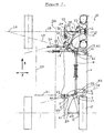
- the main suspended mass 1 of the vehicle has means 2,3,4 and 5 for holding rotational bearings into which leading suspension arm 6 and trailing suspension arm 7 are engaged by means of counterpart bearings in lugs 8 and 9 for the rear arm 7 and lugs 10 and 11 for the front arm 6.
- the longitudinal, forwards direction of normal travel of the vehicle is indicated by the arrow X, and arrow Y is the transverse direction.
- wheel hub 12 At the outer end of leading arm 6 wheel hub 12 is pivotally mounted and at the outer end of trailing arm 7 rear hub 13 (not shown) is rigidly mounted. These hubs carry front wheel assembly 14 and rear wheel assembly 15 respectively.
- leading and trailing arms 6 and 7 have upward extensions 16 and 17 respectively between which extensions is mounted sprung strut 18 by means of universal joints (or ball joints) 22.
- Other sprung struts 19, 20 and 21 are similarly mounted between the upward extensions of the other leading and trailing arms not shown.
- Front hub 12 has steering arm 23 to which is pivotally attached steering rod 24 which at its other end is pivotally engaged with rocker arm 25 pivotally mounted on the arm 6 and operated by transverse steering link 26 having means 27 for applying steering action.
- the pivot connection of rocker 25 to link 26 is arranged to be on axis 28 or as near as is practicable.
- Leading arm 6 rotates about axis 28 which is inclined to the longitudinal direction X, transverse direction Y and a vertical direction perpendicular to X and Y.
- the axis 28 is established by the positioning of chassis members 2 and 3 such that axis 28 intersects at point 30 with a vertical transverse plane 29 passing through the centre of the front wheel 14 and intersects at point 45 with a longitudinal vertical plane through the centre of the contact of wheel 14 with the road.
- Trailing arm 7 rotates about axis 38 established by the positioning of chassis members 4 and 5 such that axis 38 intersects at point 46 with a longitudinal vertical plane through the centre of contact with the ground of wheel 15.
- Leading arm 6 is shaped to accommodate wheel 14 when steered in a right hand turn as indicated by marks 37.
- Universal or constant velocity joint 31 connects half shaft 32 to disc 34 mounted on extension 33 to arm 6 and the rotation of disc 34 may be resisted by caliper assembly 35.
- Drive for the rear wheels is provided by arm 39, an extension of trailing arm 7, which carries half-shaft 40 connecting wheel 15 with chain-wheel 41 driven by chain 42 running on drive-sprocket 43.
- the bearing for sprocket 43 is mounted on a part 44 of the vehicle chassis 1 such that the centre of sprocket 43 is as close as is practicable to the axis 38.
- the vehicle is symmetrical about longitudinally extending centre-line 36, and may also have front/back symmetry where appropriate. It will be appreciated that for a four-wheel-drive vehicle, disc 34 could be replaced with a chain-wheel in a similar arrangement as for the rear wheels.
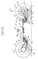
- front wheel 14 is connected via swivel hub 12 to the outer end of leading arm 6.
- Wheel 14 is braked by disc 34 and caliper assembly 35 and steered by steering rod 24 connected to rocker arm 25 operated by transverse link 26.
- Leading arm 6 is maintained in equilibrium about axis 28 which passes through lugs 10 and 11 against the upward reaction of the ground by its upward extension 16 acted upon by the combined action of sprung struts 18 and 19.
- the leading arm rotational axis 28 intersects at point 45 with line 47 in a longitudinal vertical plane through the centre of contact of wheel 14 with the ground and intersects at point 30, a selected distance from the ground, with transverse plane 29.
- Rotational axis 38 which intersects at point 46 with a longitudinal plane through the centre of contact of wheel 15 with the ground, is also arranged in this manner though not necessarily with precise symmetry.
- Rear wheel 15 is driven by chain-wheel 41 mounted on extension 39 to trailing arm 7 and connected to powered sprocket 43 by chain 42.
- Trailing arm 7 has lugs 8 and 9 through which passes its rotational axis 38.
- Arm 7 is held in equilibrium about this axis 38 against the upward reaction from the ground by upward extension 17 of arm 7 to which is attached via universal joints 22 sprung struts 18 and 21.
- each sprung strut is common to two adjacent suspension arms, thus providing an arrangement which may be termed a double linked suspension, and lines 47 and 48 are arranged to intersect a short distance from or within the zone 49 where the centre of gravity of the vehicle's suspended mass, projected onto the plane containing lines 47 and 48, is expected to be found.
Landscapes
- Engineering & Computer Science (AREA)
- Mechanical Engineering (AREA)
- Vehicle Body Suspensions (AREA)
Applications Claiming Priority (2)
| Application Number | Priority Date | Filing Date | Title |
|---|---|---|---|
| GB0809171A GB2460244A (en) | 2008-05-21 | 2008-05-21 | Vehicle suspension with linked arms |
| PCT/GB2009/001253 WO2009141603A1 (en) | 2008-05-21 | 2009-05-20 | Vehicle suspension system |
Publications (2)
| Publication Number | Publication Date |
|---|---|
| EP2296922A1 EP2296922A1 (en) | 2011-03-23 |
| EP2296922B1 true EP2296922B1 (en) | 2014-10-08 |
Family
ID=39596212
Family Applications (1)
| Application Number | Title | Priority Date | Filing Date |
|---|---|---|---|
| EP09750081.3A Active EP2296922B1 (en) | 2008-05-21 | 2009-05-20 | Vehicle suspension system |
Country Status (6)
| Country | Link |
|---|---|
| US (1) | US8317208B2 (enExample) |
| EP (1) | EP2296922B1 (enExample) |
| JP (1) | JP5702715B2 (enExample) |
| ES (1) | ES2527323T3 (enExample) |
| GB (2) | GB2460244A (enExample) |
| WO (1) | WO2009141603A1 (enExample) |
Families Citing this family (19)
| Publication number | Priority date | Publication date | Assignee | Title |
|---|---|---|---|---|
| US20100225084A1 (en) * | 2008-12-30 | 2010-09-09 | Darco Trust | Vehicle suspension system |
| DE102011082128B4 (de) * | 2011-09-05 | 2020-10-29 | Bayerische Motoren Werke Aktiengesellschaft | Fahrzeug-Radaufhängung mit über einen Umlenkhebel veränderbarer Radlast |
| FR2980398B1 (fr) | 2011-09-28 | 2014-05-02 | Univ Blaise Pascal Clermont Ii | Dispositif de suspension d'une roue, et vehicule muni d'au moins une roue equipee d'un tel dispositif de suspension |
| CA2913353C (en) * | 2012-07-03 | 2019-01-29 | Pantero Technologies Inc. | Semi-independent suspension system for a low-floor vehicle |
| WO2015187114A1 (ru) * | 2014-06-05 | 2015-12-10 | Юрий Григорьевич СИДОРЕНКО | Подвеска транспортного средства "afw" |
| DE102015112161A1 (de) * | 2015-07-24 | 2017-01-26 | FGS GmbH - Fahrzeug- und Al-Systeme | Achsvorrichtung |
| WO2017052484A1 (ru) * | 2015-09-22 | 2017-03-30 | Георгий Владимирович БЕЙЛИН | Подвеска транспортного средства "afw" |
| WO2017052486A1 (ru) * | 2015-09-22 | 2017-03-30 | Георгий Владимирович БЕЙЛИН | Подвеска транспортного средства "afw" (варианты) |
| WO2018088984A1 (ru) * | 2016-11-14 | 2018-05-17 | Георгий Владимирович БЕЙЛИН | Подвеска транспортного средства "afw-5" |
| GB201710583D0 (en) * | 2017-07-02 | 2017-08-16 | Bird Alan Bryn | Vehicle suspension |
| WO2021070186A1 (en) * | 2019-10-10 | 2021-04-15 | Ree Automotive Ltd | Dual-axle wheels suspension |
| CN111547150A (zh) * | 2020-06-12 | 2020-08-18 | 骨智医疗科技(天津) 有限公司 | 一种用于移动机器人的ppuur悬架结构 |
| CN113971312A (zh) * | 2020-07-23 | 2022-01-25 | 北京宝沃汽车股份有限公司 | 车辆悬架模型生成方法、装置、存储介质以及车辆 |
| CN112373260B (zh) * | 2020-11-26 | 2022-04-26 | 广东博智林机器人有限公司 | 减震底盘系统及移动式装置 |
| WO2022229953A1 (en) | 2021-04-26 | 2022-11-03 | Ree Automotive Ltd. | Dual-axle vehicle corner assembly |
| US11433732B1 (en) * | 2021-06-21 | 2022-09-06 | Volvo Truck Corporation | Anti-dive bar system with selective fixation |
| WO2023021510A1 (en) | 2021-08-16 | 2023-02-23 | Ree Automotive Ltd | Dual-wheels corner system with transverse suspension |
| KR20230133094A (ko) | 2022-03-10 | 2023-09-19 | 현대자동차주식회사 | 모빌리티 |
| CN119636313B (zh) * | 2025-01-02 | 2025-09-12 | 成都工业学院 | 一种横置解耦悬架 |
Family Cites Families (38)
| Publication number | Priority date | Publication date | Assignee | Title |
|---|---|---|---|---|
| GB191300965A (en) | 1912-01-26 | 1914-04-14 | Thomas Hodgson | Improvements in Motor Car and other Vehicular Spring Suspension Mechanism. |
| GB214080A (en) | 1923-04-10 | 1924-04-17 | Leonard Mortimer Baines | Improvements in or relating to spring suspensions for vehicles |
| US2067640A (en) * | 1933-01-28 | 1937-01-12 | Joseph D Madden | Stabilizer |
| FR782921A (fr) * | 1934-03-10 | 1935-07-05 | Suspension à roues conjuguées | |
| BE418100A (enExample) * | 1935-07-08 | |||
| US2166368A (en) * | 1937-05-21 | 1939-07-18 | Perron Adrian | Independent wheel suspension for automobiles |
| US2202689A (en) * | 1938-11-08 | 1940-05-28 | Eliot Samuel | Motor vehicle |
| US2318245A (en) * | 1940-09-24 | 1943-05-04 | Edwin J Mcfarland | Driving and steering mechanism for automobiles |
| BE470946A (enExample) * | 1944-02-03 | |||
| DE1028435B (de) | 1955-08-01 | 1958-04-17 | Daimler Benz Ag | Ausgleichsfederung fuer Fahrzeuge, insbesondere Kraftfahrzeuge |
| FR1222016A (fr) * | 1959-03-14 | 1960-06-07 | Installation de suspension pour véhicules | |
| DE1430938C3 (de) * | 1964-10-27 | 1972-11-16 | Daimler Benz Ag | Radaufhaengung von Kraftfahrzeugen |
| GB1179282A (en) | 1967-04-12 | 1970-01-28 | Ford Motor Co | Motor Vehicle Package. |
| FR2079967A5 (enExample) * | 1970-02-18 | 1971-11-12 | Citroen Sa | |
| US3740069A (en) | 1971-03-29 | 1973-06-19 | Moog Industries Inc | Vehicle tandem axle suspension system |
| GB1512377A (en) * | 1975-05-22 | 1978-06-01 | Bolton A | Vehicle suspensions |
| JPS5423684Y2 (enExample) * | 1975-06-27 | 1979-08-14 | ||
| US4022494A (en) * | 1975-07-07 | 1977-05-10 | Ford Motor Company | Motor vehicle rear suspension system |
| DE2553494B2 (de) * | 1975-11-28 | 1979-03-01 | Bayerische Motoren Werke Ag, 8000 Muenchen | Einzelradaufhängung für eine Hinterachse von Kraftfahrzeugen, insbesondere von Personenkraftwagen |
| FR2453037A1 (fr) | 1979-03-13 | 1980-10-31 | Ecole Nale Superieure Mecaniqu | Suspension a flexibilite variable pour vehicule |
| FR2595633B1 (fr) * | 1986-03-13 | 1988-04-29 | Marc Delery | Suspension a lames, notamment pour vehicules automobiles |
| CH676449A5 (en) | 1988-09-22 | 1991-01-31 | Leo Stahl Ag | Device to couple pairs of moving wheels of off-road vehicles |
| FR2649047B1 (fr) * | 1989-06-28 | 1991-09-13 | Delery Marc | Suspension notamment pour vehicules automobiles |
| EP0592536B1 (en) * | 1991-07-02 | 1999-05-19 | Kinetic Limited | Vehicle suspension system |
| US5562305A (en) * | 1991-12-18 | 1996-10-08 | Kinetic Limited | Vehicle suspension system |
| FR2700501B1 (fr) | 1993-01-19 | 1995-02-17 | Renault | Véhicule de franchissement d'obstacles. |
| JPH0781344A (ja) * | 1993-09-20 | 1995-03-28 | Nissan Motor Co Ltd | 前輪懸架装置 |
| AUPM448994A0 (en) * | 1994-03-15 | 1994-04-14 | Kinetic Limited | Improvements relating to vehicle suspension systems incorporating torsion bars |
| AUPO625897A0 (en) * | 1997-04-17 | 1997-05-15 | Kinetic Limited | Improvements to vehicle suspension systems |
| AUPO748897A0 (en) * | 1997-06-20 | 1997-07-17 | Kinetic Limited | Vehicle suspension system |
| GB2359527B (en) * | 2000-02-22 | 2003-05-21 | Rover Group | Vehicle suspensions |
| US6367831B1 (en) * | 2000-10-06 | 2002-04-09 | Daimlerchrysler Corporation | Manually adjustable transverse dual leaf suspension |
| US6834865B1 (en) * | 2003-07-02 | 2004-12-28 | Chih-Chin Lin | Horizontal balance control system of motor vehicle |
| WO2006016195A1 (en) | 2004-08-10 | 2006-02-16 | Dimitrios Korres | Vehicle wheel suspension system |
| JP2006327561A (ja) * | 2005-05-24 | 2006-12-07 | Ryuichi Ishikawa | 車輌の姿勢変化を減少させる方法 |
| US7625001B2 (en) * | 2006-05-12 | 2009-12-01 | Arvinmeritor Technology, Llc | Single and tandem shunted torsion bar suspensions |
| US7497452B2 (en) * | 2006-06-02 | 2009-03-03 | Husco International, Inc. | Hydro-pneumatic vehicle suspension system with a double acting cylinder and accumulators |
| GR1006455B (el) * | 2008-06-25 | 2009-06-22 | Αθανασιου Δημητριος Χατζηκακιδης | Παραμετρικο συστημα πλαισιου για οχηματα σχηματιζομενο απο τεσσερα στοιχεια αναρτησεως με εγκαρσια ραβδο στρεψεως και ομοαξονικο συστημα αποσβεστηρα μεσα σε φατνωμα που επιτρεπει την αποθηκευση κεντρικα βαρεων στοιχειων (οπως μπαταριες) |
-
2008
- 2008-05-21 GB GB0809171A patent/GB2460244A/en not_active Withdrawn
-
2009
- 2009-05-20 WO PCT/GB2009/001253 patent/WO2009141603A1/en not_active Ceased
- 2009-05-20 US US12/993,969 patent/US8317208B2/en active Active
- 2009-05-20 ES ES09750081.3T patent/ES2527323T3/es active Active
- 2009-05-20 JP JP2011510040A patent/JP5702715B2/ja active Active
- 2009-05-20 GB GB0908669A patent/GB2460169B/en active Active
- 2009-05-20 EP EP09750081.3A patent/EP2296922B1/en active Active
Also Published As
| Publication number | Publication date |
|---|---|
| GB2460169A (en) | 2009-11-25 |
| GB0809171D0 (en) | 2008-06-25 |
| EP2296922A1 (en) | 2011-03-23 |
| JP5702715B2 (ja) | 2015-04-15 |
| US8317208B2 (en) | 2012-11-27 |
| GB2460169B (en) | 2010-06-02 |
| JP2011520701A (ja) | 2011-07-21 |
| GB2460244A (en) | 2009-11-25 |
| GB0908669D0 (en) | 2009-07-01 |
| US20110084461A1 (en) | 2011-04-14 |
| WO2009141603A1 (en) | 2009-11-26 |
| ES2527323T3 (es) | 2015-01-22 |
Similar Documents
| Publication | Publication Date | Title |
|---|---|---|
| EP2296922B1 (en) | Vehicle suspension system | |
| US7976038B2 (en) | Trailing arm vehicle suspension system | |
| EP2534001B1 (en) | A vehicle with a four bar link suspension system provided with improved roll characteristics | |
| CN102216096B (zh) | 车辆悬架 | |
| AU2013251212B2 (en) | Track suspension | |
| RU2517274C2 (ru) | Независимая подвеска транспортного средства | |
| CZ261996A3 (en) | Suspension with interconnected torsional rods | |
| AU2018295425B2 (en) | Vehicle suspension | |
| US8602430B2 (en) | Vehicle air suspension | |
| US20160280037A1 (en) | Stabilizer link | |
| US2816616A (en) | Vehicle wheel suspension | |
| KR20010075191A (ko) | 제로 롤 현가 시스템 및 그 제공 방법 | |
| US6921097B2 (en) | Arrangement for wheel suspension | |
| US5184842A (en) | Vehicle suspension mechanism | |
| US9902223B2 (en) | Couplable motor vehicle with improved coupling | |
| GB2309206A (en) | Vehicle suspension system | |
| RU2509657C2 (ru) | Подвеска транспортного средства |
Legal Events
| Date | Code | Title | Description |
|---|---|---|---|
| PUAI | Public reference made under article 153(3) epc to a published international application that has entered the european phase |
Free format text: ORIGINAL CODE: 0009012 |
|
| 17P | Request for examination filed |
Effective date: 20101217 |
|
| AK | Designated contracting states |
Kind code of ref document: A1 Designated state(s): AT BE BG CH CY CZ DE DK EE ES FI FR GB GR HR HU IE IS IT LI LT LU LV MC MK MT NL NO PL PT RO SE SI SK TR |
|
| AX | Request for extension of the european patent |
Extension state: AL BA RS |
|
| DAX | Request for extension of the european patent (deleted) | ||
| 17Q | First examination report despatched |
Effective date: 20121126 |
|
| GRAP | Despatch of communication of intention to grant a patent |
Free format text: ORIGINAL CODE: EPIDOSNIGR1 |
|
| INTG | Intention to grant announced |
Effective date: 20140424 |
|
| GRAS | Grant fee paid |
Free format text: ORIGINAL CODE: EPIDOSNIGR3 |
|
| GRAA | (expected) grant |
Free format text: ORIGINAL CODE: 0009210 |
|
| RBV | Designated contracting states (corrected) |
Designated state(s): AT BE BG CH CY CZ DE DK EE ES FI FR GR HR HU IE IS IT LI LT LU LV MC MK MT NL NO PL PT RO SE SI SK TR |
|
| AK | Designated contracting states |
Kind code of ref document: B1 Designated state(s): AT BE BG CH CY CZ DE DK EE ES FI FR GR HR HU IE IS IT LI LT LU LV MC MK MT NL NO PL PT RO SE SI SK TR |
|
| REG | Reference to a national code |
Ref country code: AT Ref legal event code: REF Ref document number: 690388 Country of ref document: AT Kind code of ref document: T Effective date: 20141015 Ref country code: CH Ref legal event code: EP |
|
| REG | Reference to a national code |
Ref country code: IE Ref legal event code: FG4D |
|
| REG | Reference to a national code |
Ref country code: DE Ref legal event code: R096 Ref document number: 602009027084 Country of ref document: DE Effective date: 20141120 |
|
| REG | Reference to a national code |
Ref country code: SE Ref legal event code: TRGR |
|
| REG | Reference to a national code |
Ref country code: ES Ref legal event code: FG2A Ref document number: 2527323 Country of ref document: ES Kind code of ref document: T3 Effective date: 20150122 |
|
| REG | Reference to a national code |
Ref country code: NL Ref legal event code: VDEP Effective date: 20141008 |
|
| REG | Reference to a national code |
Ref country code: AT Ref legal event code: MK05 Ref document number: 690388 Country of ref document: AT Kind code of ref document: T Effective date: 20141008 |
|
| REG | Reference to a national code |
Ref country code: LT Ref legal event code: MG4D |
|
| PG25 | Lapsed in a contracting state [announced via postgrant information from national office to epo] |
Ref country code: NL Free format text: LAPSE BECAUSE OF FAILURE TO SUBMIT A TRANSLATION OF THE DESCRIPTION OR TO PAY THE FEE WITHIN THE PRESCRIBED TIME-LIMIT Effective date: 20141008 |
|
| PG25 | Lapsed in a contracting state [announced via postgrant information from national office to epo] |
Ref country code: NO Free format text: LAPSE BECAUSE OF FAILURE TO SUBMIT A TRANSLATION OF THE DESCRIPTION OR TO PAY THE FEE WITHIN THE PRESCRIBED TIME-LIMIT Effective date: 20150108 Ref country code: IS Free format text: LAPSE BECAUSE OF FAILURE TO SUBMIT A TRANSLATION OF THE DESCRIPTION OR TO PAY THE FEE WITHIN THE PRESCRIBED TIME-LIMIT Effective date: 20150208 Ref country code: FI Free format text: LAPSE BECAUSE OF FAILURE TO SUBMIT A TRANSLATION OF THE DESCRIPTION OR TO PAY THE FEE WITHIN THE PRESCRIBED TIME-LIMIT Effective date: 20141008 Ref country code: LT Free format text: LAPSE BECAUSE OF FAILURE TO SUBMIT A TRANSLATION OF THE DESCRIPTION OR TO PAY THE FEE WITHIN THE PRESCRIBED TIME-LIMIT Effective date: 20141008 Ref country code: PT Free format text: LAPSE BECAUSE OF FAILURE TO SUBMIT A TRANSLATION OF THE DESCRIPTION OR TO PAY THE FEE WITHIN THE PRESCRIBED TIME-LIMIT Effective date: 20150209 |
|
| PG25 | Lapsed in a contracting state [announced via postgrant information from national office to epo] |
Ref country code: PL Free format text: LAPSE BECAUSE OF FAILURE TO SUBMIT A TRANSLATION OF THE DESCRIPTION OR TO PAY THE FEE WITHIN THE PRESCRIBED TIME-LIMIT Effective date: 20141008 Ref country code: GR Free format text: LAPSE BECAUSE OF FAILURE TO SUBMIT A TRANSLATION OF THE DESCRIPTION OR TO PAY THE FEE WITHIN THE PRESCRIBED TIME-LIMIT Effective date: 20150109 Ref country code: AT Free format text: LAPSE BECAUSE OF FAILURE TO SUBMIT A TRANSLATION OF THE DESCRIPTION OR TO PAY THE FEE WITHIN THE PRESCRIBED TIME-LIMIT Effective date: 20141008 Ref country code: CY Free format text: LAPSE BECAUSE OF FAILURE TO SUBMIT A TRANSLATION OF THE DESCRIPTION OR TO PAY THE FEE WITHIN THE PRESCRIBED TIME-LIMIT Effective date: 20141008 Ref country code: HR Free format text: LAPSE BECAUSE OF FAILURE TO SUBMIT A TRANSLATION OF THE DESCRIPTION OR TO PAY THE FEE WITHIN THE PRESCRIBED TIME-LIMIT Effective date: 20141008 Ref country code: LV Free format text: LAPSE BECAUSE OF FAILURE TO SUBMIT A TRANSLATION OF THE DESCRIPTION OR TO PAY THE FEE WITHIN THE PRESCRIBED TIME-LIMIT Effective date: 20141008 |
|
| REG | Reference to a national code |
Ref country code: DE Ref legal event code: R097 Ref document number: 602009027084 Country of ref document: DE |
|
| PG25 | Lapsed in a contracting state [announced via postgrant information from national office to epo] |
Ref country code: RO Free format text: LAPSE BECAUSE OF FAILURE TO SUBMIT A TRANSLATION OF THE DESCRIPTION OR TO PAY THE FEE WITHIN THE PRESCRIBED TIME-LIMIT Effective date: 20141008 Ref country code: SK Free format text: LAPSE BECAUSE OF FAILURE TO SUBMIT A TRANSLATION OF THE DESCRIPTION OR TO PAY THE FEE WITHIN THE PRESCRIBED TIME-LIMIT Effective date: 20141008 Ref country code: DK Free format text: LAPSE BECAUSE OF FAILURE TO SUBMIT A TRANSLATION OF THE DESCRIPTION OR TO PAY THE FEE WITHIN THE PRESCRIBED TIME-LIMIT Effective date: 20141008 Ref country code: EE Free format text: LAPSE BECAUSE OF FAILURE TO SUBMIT A TRANSLATION OF THE DESCRIPTION OR TO PAY THE FEE WITHIN THE PRESCRIBED TIME-LIMIT Effective date: 20141008 |
|
| PLBE | No opposition filed within time limit |
Free format text: ORIGINAL CODE: 0009261 |
|
| STAA | Information on the status of an ep patent application or granted ep patent |
Free format text: STATUS: NO OPPOSITION FILED WITHIN TIME LIMIT |
|
| 26N | No opposition filed |
Effective date: 20150709 |
|
| REG | Reference to a national code |
Ref country code: CH Ref legal event code: PL |
|
| PG25 | Lapsed in a contracting state [announced via postgrant information from national office to epo] |
Ref country code: LI Free format text: LAPSE BECAUSE OF NON-PAYMENT OF DUE FEES Effective date: 20150531 Ref country code: CH Free format text: LAPSE BECAUSE OF NON-PAYMENT OF DUE FEES Effective date: 20150531 Ref country code: LU Free format text: LAPSE BECAUSE OF FAILURE TO SUBMIT A TRANSLATION OF THE DESCRIPTION OR TO PAY THE FEE WITHIN THE PRESCRIBED TIME-LIMIT Effective date: 20150520 Ref country code: MC Free format text: LAPSE BECAUSE OF FAILURE TO SUBMIT A TRANSLATION OF THE DESCRIPTION OR TO PAY THE FEE WITHIN THE PRESCRIBED TIME-LIMIT Effective date: 20141008 |
|
| REG | Reference to a national code |
Ref country code: IE Ref legal event code: MM4A |
|
| PG25 | Lapsed in a contracting state [announced via postgrant information from national office to epo] |
Ref country code: SI Free format text: LAPSE BECAUSE OF FAILURE TO SUBMIT A TRANSLATION OF THE DESCRIPTION OR TO PAY THE FEE WITHIN THE PRESCRIBED TIME-LIMIT Effective date: 20141008 |
|
| PG25 | Lapsed in a contracting state [announced via postgrant information from national office to epo] |
Ref country code: IE Free format text: LAPSE BECAUSE OF NON-PAYMENT OF DUE FEES Effective date: 20150520 |
|
| REG | Reference to a national code |
Ref country code: FR Ref legal event code: PLFP Year of fee payment: 8 |
|
| PGFP | Annual fee paid to national office [announced via postgrant information from national office to epo] |
Ref country code: SE Payment date: 20160509 Year of fee payment: 8 |
|
| PG25 | Lapsed in a contracting state [announced via postgrant information from national office to epo] |
Ref country code: MT Free format text: LAPSE BECAUSE OF FAILURE TO SUBMIT A TRANSLATION OF THE DESCRIPTION OR TO PAY THE FEE WITHIN THE PRESCRIBED TIME-LIMIT Effective date: 20141008 |
|
| REG | Reference to a national code |
Ref country code: FR Ref legal event code: PLFP Year of fee payment: 9 |
|
| PG25 | Lapsed in a contracting state [announced via postgrant information from national office to epo] |
Ref country code: HU Free format text: LAPSE BECAUSE OF FAILURE TO SUBMIT A TRANSLATION OF THE DESCRIPTION OR TO PAY THE FEE WITHIN THE PRESCRIBED TIME-LIMIT; INVALID AB INITIO Effective date: 20090520 Ref country code: BG Free format text: LAPSE BECAUSE OF FAILURE TO SUBMIT A TRANSLATION OF THE DESCRIPTION OR TO PAY THE FEE WITHIN THE PRESCRIBED TIME-LIMIT Effective date: 20141008 |
|
| PG25 | Lapsed in a contracting state [announced via postgrant information from national office to epo] |
Ref country code: TR Free format text: LAPSE BECAUSE OF FAILURE TO SUBMIT A TRANSLATION OF THE DESCRIPTION OR TO PAY THE FEE WITHIN THE PRESCRIBED TIME-LIMIT Effective date: 20141008 |
|
| PG25 | Lapsed in a contracting state [announced via postgrant information from national office to epo] |
Ref country code: BE Free format text: LAPSE BECAUSE OF FAILURE TO SUBMIT A TRANSLATION OF THE DESCRIPTION OR TO PAY THE FEE WITHIN THE PRESCRIBED TIME-LIMIT Effective date: 20141008 |
|
| REG | Reference to a national code |
Ref country code: SE Ref legal event code: EUG |
|
| PG25 | Lapsed in a contracting state [announced via postgrant information from national office to epo] |
Ref country code: SE Free format text: LAPSE BECAUSE OF NON-PAYMENT OF DUE FEES Effective date: 20170521 |
|
| REG | Reference to a national code |
Ref country code: FR Ref legal event code: PLFP Year of fee payment: 10 |
|
| PG25 | Lapsed in a contracting state [announced via postgrant information from national office to epo] |
Ref country code: MK Free format text: LAPSE BECAUSE OF FAILURE TO SUBMIT A TRANSLATION OF THE DESCRIPTION OR TO PAY THE FEE WITHIN THE PRESCRIBED TIME-LIMIT Effective date: 20141008 |
|
| REG | Reference to a national code |
Ref country code: DE Ref legal event code: R081 Ref document number: 602009027084 Country of ref document: DE Owner name: FREEDM LIMITED, HENLEY-IN-ARDEN, GB Free format text: FORMER OWNER: BIRD, ALAN BRYN, TAMWORTH, GB Ref country code: DE Ref legal event code: R081 Ref document number: 602009027084 Country of ref document: DE Owner name: FREEDOM LIMITED, HENLEY-IN-ARDEN, GB Free format text: FORMER OWNER: BIRD, ALAN BRYN, TAMWORTH, GB |
|
| REG | Reference to a national code |
Ref country code: DE Ref legal event code: R081 Ref document number: 602009027084 Country of ref document: DE Owner name: FREEDM LIMITED, HENLEY-IN-ARDEN, GB Free format text: FORMER OWNER: FREEDOM LIMITED, HENLEY-IN-ARDEN, WARWICKSHIRE, GB |
|
| PGFP | Annual fee paid to national office [announced via postgrant information from national office to epo] |
Ref country code: DE Payment date: 20250528 Year of fee payment: 17 |
|
| PGFP | Annual fee paid to national office [announced via postgrant information from national office to epo] |
Ref country code: ES Payment date: 20250611 Year of fee payment: 17 |
|
| PGFP | Annual fee paid to national office [announced via postgrant information from national office to epo] |
Ref country code: IT Payment date: 20250522 Year of fee payment: 17 |
|
| PGFP | Annual fee paid to national office [announced via postgrant information from national office to epo] |
Ref country code: FR Payment date: 20250526 Year of fee payment: 17 |
|
| PGFP | Annual fee paid to national office [announced via postgrant information from national office to epo] |
Ref country code: CZ Payment date: 20250506 Year of fee payment: 17 |