EP2295889A2 - Réservoir de condensation dans un cycle de pompe à chaleur - Google Patents
Réservoir de condensation dans un cycle de pompe à chaleur Download PDFInfo
- Publication number
- EP2295889A2 EP2295889A2 EP10170652A EP10170652A EP2295889A2 EP 2295889 A2 EP2295889 A2 EP 2295889A2 EP 10170652 A EP10170652 A EP 10170652A EP 10170652 A EP10170652 A EP 10170652A EP 2295889 A2 EP2295889 A2 EP 2295889A2
- Authority
- EP
- European Patent Office
- Prior art keywords
- condensation
- heat exchanger
- boiler
- heating
- store
- Prior art date
- Legal status (The legal status is an assumption and is not a legal conclusion. Google has not performed a legal analysis and makes no representation as to the accuracy of the status listed.)
- Granted
Links
Images
Classifications
-
- F—MECHANICAL ENGINEERING; LIGHTING; HEATING; WEAPONS; BLASTING
- F24—HEATING; RANGES; VENTILATING
- F24H—FLUID HEATERS, e.g. WATER OR AIR HEATERS, HAVING HEAT-GENERATING MEANS, e.g. HEAT PUMPS, IN GENERAL
- F24H4/00—Fluid heaters characterised by the use of heat pumps
- F24H4/02—Water heaters
- F24H4/04—Storage heaters
-
- F—MECHANICAL ENGINEERING; LIGHTING; HEATING; WEAPONS; BLASTING
- F24—HEATING; RANGES; VENTILATING
- F24D—DOMESTIC- OR SPACE-HEATING SYSTEMS, e.g. CENTRAL HEATING SYSTEMS; DOMESTIC HOT-WATER SUPPLY SYSTEMS; ELEMENTS OR COMPONENTS THEREFOR
- F24D11/00—Central heating systems using heat accumulated in storage masses
- F24D11/02—Central heating systems using heat accumulated in storage masses using heat pumps
- F24D11/0214—Central heating systems using heat accumulated in storage masses using heat pumps water heating system
-
- F—MECHANICAL ENGINEERING; LIGHTING; HEATING; WEAPONS; BLASTING
- F24—HEATING; RANGES; VENTILATING
- F24D—DOMESTIC- OR SPACE-HEATING SYSTEMS, e.g. CENTRAL HEATING SYSTEMS; DOMESTIC HOT-WATER SUPPLY SYSTEMS; ELEMENTS OR COMPONENTS THEREFOR
- F24D3/00—Hot-water central heating systems
- F24D3/08—Hot-water central heating systems in combination with systems for domestic hot-water supply
- F24D3/082—Hot water storage tanks specially adapted therefor
-
- F—MECHANICAL ENGINEERING; LIGHTING; HEATING; WEAPONS; BLASTING
- F28—HEAT EXCHANGE IN GENERAL
- F28D—HEAT-EXCHANGE APPARATUS, NOT PROVIDED FOR IN ANOTHER SUBCLASS, IN WHICH THE HEAT-EXCHANGE MEDIA DO NOT COME INTO DIRECT CONTACT
- F28D20/00—Heat storage plants or apparatus in general; Regenerative heat-exchange apparatus not covered by groups F28D17/00 or F28D19/00
- F28D20/0034—Heat storage plants or apparatus in general; Regenerative heat-exchange apparatus not covered by groups F28D17/00 or F28D19/00 using liquid heat storage material
- F28D20/0039—Heat storage plants or apparatus in general; Regenerative heat-exchange apparatus not covered by groups F28D17/00 or F28D19/00 using liquid heat storage material with stratification of the heat storage material
-
- F—MECHANICAL ENGINEERING; LIGHTING; HEATING; WEAPONS; BLASTING
- F28—HEAT EXCHANGE IN GENERAL
- F28G—CLEANING OF INTERNAL OR EXTERNAL SURFACES OF HEAT-EXCHANGE OR HEAT-TRANSFER CONDUITS, e.g. WATER TUBES OR BOILERS
- F28G9/00—Cleaning by flushing or washing, e.g. with chemical solvents
-
- F—MECHANICAL ENGINEERING; LIGHTING; HEATING; WEAPONS; BLASTING
- F25—REFRIGERATION OR COOLING; COMBINED HEATING AND REFRIGERATION SYSTEMS; HEAT PUMP SYSTEMS; MANUFACTURE OR STORAGE OF ICE; LIQUEFACTION SOLIDIFICATION OF GASES
- F25B—REFRIGERATION MACHINES, PLANTS OR SYSTEMS; COMBINED HEATING AND REFRIGERATION SYSTEMS; HEAT PUMP SYSTEMS
- F25B2339/00—Details of evaporators; Details of condensers
- F25B2339/04—Details of condensers
- F25B2339/047—Water-cooled condensers
-
- F—MECHANICAL ENGINEERING; LIGHTING; HEATING; WEAPONS; BLASTING
- F25—REFRIGERATION OR COOLING; COMBINED HEATING AND REFRIGERATION SYSTEMS; HEAT PUMP SYSTEMS; MANUFACTURE OR STORAGE OF ICE; LIQUEFACTION SOLIDIFICATION OF GASES
- F25B—REFRIGERATION MACHINES, PLANTS OR SYSTEMS; COMBINED HEATING AND REFRIGERATION SYSTEMS; HEAT PUMP SYSTEMS
- F25B2500/00—Problems to be solved
- F25B2500/01—Geometry problems, e.g. for reducing size
-
- F—MECHANICAL ENGINEERING; LIGHTING; HEATING; WEAPONS; BLASTING
- F25—REFRIGERATION OR COOLING; COMBINED HEATING AND REFRIGERATION SYSTEMS; HEAT PUMP SYSTEMS; MANUFACTURE OR STORAGE OF ICE; LIQUEFACTION SOLIDIFICATION OF GASES
- F25B—REFRIGERATION MACHINES, PLANTS OR SYSTEMS; COMBINED HEATING AND REFRIGERATION SYSTEMS; HEAT PUMP SYSTEMS
- F25B30/00—Heat pumps
- F25B30/02—Heat pumps of the compression type
-
- F—MECHANICAL ENGINEERING; LIGHTING; HEATING; WEAPONS; BLASTING
- F28—HEAT EXCHANGE IN GENERAL
- F28D—HEAT-EXCHANGE APPARATUS, NOT PROVIDED FOR IN ANOTHER SUBCLASS, IN WHICH THE HEAT-EXCHANGE MEDIA DO NOT COME INTO DIRECT CONTACT
- F28D20/00—Heat storage plants or apparatus in general; Regenerative heat-exchange apparatus not covered by groups F28D17/00 or F28D19/00
- F28D2020/0065—Details, e.g. particular heat storage tanks, auxiliary members within tanks
- F28D2020/0069—Distributing arrangements; Fluid deflecting means
-
- F—MECHANICAL ENGINEERING; LIGHTING; HEATING; WEAPONS; BLASTING
- F28—HEAT EXCHANGE IN GENERAL
- F28D—HEAT-EXCHANGE APPARATUS, NOT PROVIDED FOR IN ANOTHER SUBCLASS, IN WHICH THE HEAT-EXCHANGE MEDIA DO NOT COME INTO DIRECT CONTACT
- F28D20/00—Heat storage plants or apparatus in general; Regenerative heat-exchange apparatus not covered by groups F28D17/00 or F28D19/00
- F28D2020/0065—Details, e.g. particular heat storage tanks, auxiliary members within tanks
- F28D2020/0078—Heat exchanger arrangements
-
- F—MECHANICAL ENGINEERING; LIGHTING; HEATING; WEAPONS; BLASTING
- F28—HEAT EXCHANGE IN GENERAL
- F28D—HEAT-EXCHANGE APPARATUS, NOT PROVIDED FOR IN ANOTHER SUBCLASS, IN WHICH THE HEAT-EXCHANGE MEDIA DO NOT COME INTO DIRECT CONTACT
- F28D20/00—Heat storage plants or apparatus in general; Regenerative heat-exchange apparatus not covered by groups F28D17/00 or F28D19/00
- F28D2020/0065—Details, e.g. particular heat storage tanks, auxiliary members within tanks
- F28D2020/0086—Partitions
-
- Y—GENERAL TAGGING OF NEW TECHNOLOGICAL DEVELOPMENTS; GENERAL TAGGING OF CROSS-SECTIONAL TECHNOLOGIES SPANNING OVER SEVERAL SECTIONS OF THE IPC; TECHNICAL SUBJECTS COVERED BY FORMER USPC CROSS-REFERENCE ART COLLECTIONS [XRACs] AND DIGESTS
- Y02—TECHNOLOGIES OR APPLICATIONS FOR MITIGATION OR ADAPTATION AGAINST CLIMATE CHANGE
- Y02E—REDUCTION OF GREENHOUSE GAS [GHG] EMISSIONS, RELATED TO ENERGY GENERATION, TRANSMISSION OR DISTRIBUTION
- Y02E60/00—Enabling technologies; Technologies with a potential or indirect contribution to GHG emissions mitigation
- Y02E60/14—Thermal energy storage
Definitions
- the present invention relates to a condensation reservoir for use in a heat pump cycle and a heat pump cycle having a condensation reservoir.
- Heat pump systems usually comprise an evaporator and a condenser, meanwhile there are integrated condensation storages which form the storage boiler of a heating system and in which condensation heat exchanger of the heat pump circuit is integrated.
- This object is achieved by a condensation store according to claim 1 and a heat pump cycle according to claim 15.
- advantageous Further developments of the invention are the subject of the dependent claims.
- the capacitor in the condensation memory according to the invention is characterized in that it is considerably oversized, for example, by a factor of 2 is greater than would theoretically be required according to the following list.
- boiler and storage tank are used synonymously.
- fluid is meant a conventional cooling / heating means of a heat pump cycle.
- This formula is used to calculate the area of the heat exchanger in practice. It corresponds to the theoretical value according to claim 16.
- the condensation heat exchange area used according to the present invention is at least a factor of 2 times this theoretical value.
- the area is even larger than the corresponding theoretical value by at least a factor of 3, or factor 4 to factor 8 or more.
- the surface of the heat exchanger should be at least 0.7 square meters / kW heating power of the heat pump cycle, preferably more than 0.8 square meters / kW heating power, in particular more than 1 square meter / kW heating power.
- condensation point for example, from 40 - 45 degrees C so that led to low flow temperatures below the condensation point, which was at best sufficient for underfloor heating.
- the condensation point is no longer the limiting factor for the height of the flow temperature, but you can - by previous economic considerations completely outlandish - strong oversizing of the heat exchanger use the overtemperature range to boost he flow temperature in the boiler.
- the improved efficiency is achieved, in particular, in the case of large boilers which have a size of at least 200 l, preferably at least 350 l, and in particular greater than 500 l.
- This considerable size of the storage tank has the advantage that on the one hand the heat output through the oversized heat exchanger better, ie with lower losses in the boiler located in the heating and service water can be transferred.
- the large boiler content allows a relatively long maintenance of the temperature of the heating and service water stored in the boiler and thus, for example, a shutdown of the heat pump at peak times.
- the boiler is not only intended for domestic water heating but also for domestic water heating and heating.
- the large volume of heating and service water in the boiler between boiler wall and heat exchanger can be used well for effective heat transfer.
- only one boiler is needed for heating water and process water.
- the excess temperature energy portion is used much better, if in the upper part of the memory device is provided which controls the heat exchange between the condensation heat exchanger and the water in the boiler so that the differential temperature between the boiler water and the fluid is reduced in the condensation heat exchanger.
- the access of the water in the boiler is limited to the condensation heat exchanger. Because if less water comes into contact with the condensation heat exchanger, this is heated more and the fluid in the condensation heat exchanger does not cool down so quickly. In the end, in turn, a stronger heating of the water in the boiler is achieved, which in turn allows a substantial increase in the flow temperature.
- the device for reducing the flow rate of boiler water, which comes into contact with the heat exchanger can be structurally realized by the condensation heat exchanger itself or constructive in the arrangement of the heat exchanger in the boiler, eg by the tight arrangement of at least the overtemperature of the heat exchanger near the walls of the storage tank ,
- the overtemperature range of the heat exchanger is the one in which the temperature of the fluid in the condenser is above the condensation temperature.
- the device is formed in a structurally simple manner by partition walls, which preferably extend at a defined distance from the condensation heat exchanger surfaces, preferably vertically.
- partition walls which preferably extend at a defined distance from the condensation heat exchanger surfaces, preferably vertically.
- the water flows slowly between these partitions and the condensation heat exchanger in the manner of a chimney effect, which reduces the heat exchange between the heat exchanger and the heating water in the boiler and leads to a strong heating of the water temperature in the boiler via the condensation temperature of the fluid.
- partition walls which preferably extend at a defined distance from the condensation heat exchanger surfaces, preferably vertically.
- a normal exchange of the water preferably over the entire cross section of the boiler, take place.
- the opening for the flow temperature connection of a Walkerwasserniklaufs preferably opens in the upper part of the partition wall or above the partition in the boiler, where the water temperature is heated above the condensation temperature.
- the condensation heat exchanger annular parallel and at a small distance to the inner walls the boiler is arranged.
- the distance should preferably be between 2 and 20 cm.
- the fluid is preferably in helically downwardly extending flow channels, e.g. Guided pipes so that it flows slowly through the boiler in the condenser from top to bottom, while the water flows in countercurrent by the heating in the boiler from bottom to top.
- the flow channels may be provided with surface structures for improving the heat exchange in a conventional manner.
- the condensation heat exchanger has vertical sections which are connected to one another, wherein the upper section converts the excess temperature component and condensation component and the lower component the subcooling component. In the lower part, a part of the condensation heat can also be converted.
- the boiler is designed in the form of a circular cylinder and the heat exchanger is arranged annularly on the inner walls a small distance of a few centimeters and further on the inside of the heat exchanger, an annular partition is also arranged at a distance of a few centimeters ,
- the distance between the condensation heat exchanger and the inner wall of the boiler as well as between the condensation heat exchanger and the partition wall should be between 2 and 20 cm, preferably between 1 and 20 cm, preferably between 2 and 10 cm.
- the area of the condensing heat exchanger should cover at least 50%, preferably at least 60%, of the inner surface of the vertical boiler wall in the case of the condenser or condensing heat exchanger at a small distance from the inner wall of the boiler.
- the boiler In order to be able to set a desired flow temperature, the boiler should have at least one heating flow connection in its upper area and one heating flow connection in its middle area. Then, for example, a mixing fitting can be connected to these two ports, through which an arbitrary flow temperature between the center tap and the upper tap can be adjusted.
- the condensation storage preferably has a heating return connection, which opens into a known layer tube, which runs vertically in the boiler and has several outlets at different heights of the boiler.
- a laminated tube has a very large diameter of, for example, 5 - 15 cm, preferably 7-10 cm and contributes to the fact that the water flows through an exit at such a height in the boiler, in which height the same temperature as the return temperature prevails , In this way it is avoided that the cooler water is whirled up from the very bottom in the boiler again and again.
- a flushing device is arranged in the upper region of the storage tank above the condensation heat exchanger.
- the rinsing device is preferably designed as a ring tube with downwardly directed rinsing openings. Through them, a cleaning liquid or water can be sprayed with high pressure on the condensation heat exchanger to clean it of impurities.
- condensation storage is also to be used for process water treatment, it is advantageous to provide a vertically extending coiled tubing for domestic water heating in the interior of the boiler.
- the entire boiler can also be used instead of heating the water for a heating circuit for heating water for a domestic water circuit.
- the evaporator of the heat cycle can be any conventional evaporator, which is preferably arranged in the outer area of a building.
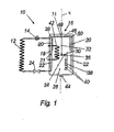
- FIG. 1 shows a heat cycle with an integrated condensation storage.
- the heat cycle 10 off FIG. 1 consists of an evaporator 12, a downstream in the direction of flow of the compressor 14, the output of which is connected to a capacitor 16 arranged in a condenser 16 capacitor.
- the condenser 18 (or condensation heat exchanger) includes an upper condensation heat exchanger section 20 and a lower condensation heat exchanger section 22 connected thereto.
- the outlet of the condenser 18 is connected to an expansion valve 24, the outlet of which is in turn connected to the evaporator 12.
- the components evaporator, compressor and expansion valve of the heat cycle 10 are known per se components and are not explained here.
- the storage tank 26 has the shape of a cylinder about the rotation axis x with a circular base.
- the two superimposed annular heat exchanger sections 20 and 22 of the capacitor 18 are arranged, which are also arranged rotationally symmetrical about the axis of rotation x except their connections.
- the two condensation heat exchanger sections 20 and 22, due to their peculiar formation, with which they cover a large proportion of the inner surface of the storage tank 26, a very large area.
- annular partition wall 28 is arranged, which is arranged rotationally symmetrical about the axis x at a small distance from the upper condensation heat exchanger section 20 and extends vertically.
- the distance between the upper condensation heat exchanger section 20 and the inner wall of the storage vessel 26 and the distance of the partition wall 28 from the upper condensation heat exchanger section 20 are comparatively small, preferably between 1 cm and 20 cm, preferably between 2 cm and 10 cm, so that a certain chimney effect is achieved in this annular area between the inner wall of the storage tank 26 and partition 28.
- the storage tank further includes a heating flow connection 30, which opens via a vertical pipe 32 with its opening 31 in the upper portion of the boiler 26, ie in a region above the partition wall 28.
- a central heating flow connection 34 in the central region of the boiler 26 is provided , between the upper heating flow connection 30 and the middle heating flow connection 34 , a mixing valve (not shown) can preferably be arranged, by means of which the flow temperature of the heating can be set individually.
- the storage tank 26 has a heating return connection 36, which is preferably large via a layer tube 38 Diameter, for example between 5 and 15 cm diameter is connected to the lower area of the storage tank.
- the connection of the layer tube 38 with the lower portion of the storage vessel 26 via many openings 40, wherein the heating water automatically enters through the opening 40 in the lower region of the storage tank 26, which corresponds to the temperature of the heating return.
- a layer tube for a heating return is known per se and is therefore not explained in detail.
- the storage tank 26 may still be provided a stainless steel coil 42 for a domestic water heating. It is also advantageous if an emptying opening 44 is provided on the floor for maintenance purposes.
- a flushing device 46 is provided in the upper region of the storage tank 26, which is connected via a flushing connection 48 with a concentric about the axis of rotation x extending annular tube, which has arranged above the condenser 18 and downwardly directed flushing openings 50.
- the upper condensing heat exchanger section 20 and the lower condensing heat exchanger section 22, which are connected to each other via a connecting line 21, occupy a large portion of the inner surface of the storage vessel 26.
- the condensation heat exchanger or condenser 18 is relative to the theoretical one required heat exchanger surface is greatly oversized, in particular at least by a factor of 2, preferably even by a factor of 3 and more. In this way, it is possible to optimally utilize the energies that can be transposed in the region of the capacitor 18 in the overtemperature range, in the condensation range and in the subcooling range, which greatly increases the effectiveness of the condensation accumulator.
- each element can preferably also be formed multiple or multiple parts.
- other features are optional, e.g. the subdivision of the condenser into an upper and a lower condensation heat exchanger section, and / or the shape of the condenser 18 and its arrangement in the storage vessel 26.
Landscapes
- Engineering & Computer Science (AREA)
- Mechanical Engineering (AREA)
- General Engineering & Computer Science (AREA)
- Physics & Mathematics (AREA)
- Thermal Sciences (AREA)
- Chemical & Material Sciences (AREA)
- Combustion & Propulsion (AREA)
- Water Supply & Treatment (AREA)
- Heat-Pump Type And Storage Water Heaters (AREA)
- Other Air-Conditioning Systems (AREA)
- Heat-Exchange Devices With Radiators And Conduit Assemblies (AREA)
Priority Applications (1)
| Application Number | Priority Date | Filing Date | Title |
|---|---|---|---|
| DE202010013659U DE202010013659U1 (de) | 2009-07-27 | 2010-07-23 | Kondensationsspeicher in einem Wärmepumpenkreislauf |
Applications Claiming Priority (1)
| Application Number | Priority Date | Filing Date | Title |
|---|---|---|---|
| DE102009034879A DE102009034879A1 (de) | 2009-07-27 | 2009-07-27 | Kondensationsspeicher in einem Wärmepumpenkreislauf |
Publications (3)
| Publication Number | Publication Date |
|---|---|
| EP2295889A2 true EP2295889A2 (fr) | 2011-03-16 |
| EP2295889A3 EP2295889A3 (fr) | 2012-04-25 |
| EP2295889B1 EP2295889B1 (fr) | 2015-04-22 |
Family
ID=42668452
Family Applications (1)
| Application Number | Title | Priority Date | Filing Date |
|---|---|---|---|
| EP10170652.1A Not-in-force EP2295889B1 (fr) | 2009-07-27 | 2010-07-23 | Cycle de pompe à chaleur avec un réservoir de condensation |
Country Status (2)
| Country | Link |
|---|---|
| EP (1) | EP2295889B1 (fr) |
| DE (2) | DE102009034879A1 (fr) |
Cited By (3)
| Publication number | Priority date | Publication date | Assignee | Title |
|---|---|---|---|---|
| EP2860469A1 (fr) * | 2013-10-11 | 2015-04-15 | Nederlandse Organisatie voor toegepast -natuurwetenschappelijk onderzoek TNO | Chauffe-eau |
| EP3037743A1 (fr) * | 2014-12-23 | 2016-06-29 | ROTEX Heating Systems GmbH | Systeme de chauffage d'eau sanitaire |
| EP4043801A1 (fr) * | 2021-02-10 | 2022-08-17 | Daikin Industries, Ltd. | Système de production de chaleur pour l'eau chaude domestique ou le chauffage central |
Families Citing this family (3)
| Publication number | Priority date | Publication date | Assignee | Title |
|---|---|---|---|---|
| DE102012017343B4 (de) * | 2012-08-29 | 2015-06-11 | Johannes Georg Mehlig | Dezentraler Warmwasser-Bereiter/ -Speicher |
| EP2980492A1 (fr) * | 2014-07-29 | 2016-02-03 | Johannes Paul Ennemoser | Réservoir thermique à écoulement libre |
| EP3892925B1 (fr) * | 2020-04-08 | 2024-02-14 | Vattenfall AB | Système de chauffage, procédé, programme informatique et support lisible par ordinateur, et dispositif de commande |
Family Cites Families (12)
| Publication number | Priority date | Publication date | Assignee | Title |
|---|---|---|---|---|
| GB1571659A (en) * | 1976-10-21 | 1980-07-16 | Dec Int | Combined storage tank and heat exchanger unit and a water heating system incorporating a said unit |
| AU3869778A (en) * | 1977-08-12 | 1980-02-14 | Mueller P Company | Condenser |
| DE3032953A1 (de) * | 1979-09-14 | 1981-04-02 | Pumpenfabrik Ernst Vogel, Stockerau, Niederösterreich | Waermepumpanlage |
| DE3142536A1 (de) * | 1981-10-27 | 1983-05-05 | Bosch-Siemens Hausgeräte GmbH, 7000 Stuttgart | Waermepumpe, insbesondere brauchwasser-waermepumpe |
| DE19731351A1 (de) * | 1997-07-22 | 1999-01-28 | Robionek Hans Joachim | Speicherwassererwärmer |
| DE20207691U1 (de) * | 2002-05-16 | 2002-09-12 | Möller, Hans, Prof. Dipl.-Ing., 44627 Herne | Multivalente Elektro-Diesel-Wärmepumpe |
| DE102004018034B4 (de) * | 2004-04-14 | 2014-07-24 | Stiebel Eltron Gmbh & Co. Kg | Verfahren zur Einschaltung einer Wärmepumpe in Verbindung mit einem Brauchwasserspeicher für Wärmepumpen |
| DE102005001511A1 (de) * | 2005-01-13 | 2006-07-27 | Paradigma Energie- Und Umwelttechnik Gmbh & Co. Kg | Thermische Schichtleiteinrichtung für Oberflächenwärmetauscher |
| DE102005051663A1 (de) * | 2005-10-28 | 2007-05-03 | Robert Kremer | Heizwasser-Schichtenspeicher mit integriertem Durchfluss-Trinkwassererwärmer aus Membran-Ovalrohr |
| DE202006009009U1 (de) * | 2006-06-08 | 2007-10-18 | Dietz, Erwin | Wärmeübertrager |
| JP2008138991A (ja) * | 2006-12-05 | 2008-06-19 | Sanyo Electric Co Ltd | 加熱タンク及び貯湯タンク |
| DE102008021804A1 (de) * | 2008-04-03 | 2009-10-08 | WISAG Gebäude- und Industrieservice Nord-West GmbH | Heizvorrichtung |
-
2009
- 2009-07-27 DE DE102009034879A patent/DE102009034879A1/de not_active Withdrawn
-
2010
- 2010-07-23 DE DE202010013659U patent/DE202010013659U1/de not_active Expired - Lifetime
- 2010-07-23 EP EP10170652.1A patent/EP2295889B1/fr not_active Not-in-force
Non-Patent Citations (1)
| Title |
|---|
| None |
Cited By (5)
| Publication number | Priority date | Publication date | Assignee | Title |
|---|---|---|---|---|
| EP2860469A1 (fr) * | 2013-10-11 | 2015-04-15 | Nederlandse Organisatie voor toegepast -natuurwetenschappelijk onderzoek TNO | Chauffe-eau |
| WO2015053630A1 (fr) * | 2013-10-11 | 2015-04-16 | Nederlandse Organisatie Voor Toegepast-Natuurwetenschappelijk Onderzoek Tno | Chauffe-eau |
| EP3037743A1 (fr) * | 2014-12-23 | 2016-06-29 | ROTEX Heating Systems GmbH | Systeme de chauffage d'eau sanitaire |
| EP4043801A1 (fr) * | 2021-02-10 | 2022-08-17 | Daikin Industries, Ltd. | Système de production de chaleur pour l'eau chaude domestique ou le chauffage central |
| WO2022172867A1 (fr) * | 2021-02-10 | 2022-08-18 | Daikin Industries, Ltd. | Système de production de chaleur pour eau chaude sanitaire ou chauffage central |
Also Published As
| Publication number | Publication date |
|---|---|
| DE202010013659U1 (de) | 2010-12-16 |
| EP2295889A3 (fr) | 2012-04-25 |
| EP2295889B1 (fr) | 2015-04-22 |
| DE102009034879A1 (de) | 2011-02-10 |
Similar Documents
| Publication | Publication Date | Title |
|---|---|---|
| EP2295889B1 (fr) | Cycle de pompe à chaleur avec un réservoir de condensation | |
| EP0099875B1 (fr) | Dispositif pour chauffer de l'eau de chauffage et de l'eau de consommation | |
| DE202006016100U1 (de) | Solarkollektorsystem | |
| AT510440B1 (de) | Fluidspeicher | |
| DE102010005992A1 (de) | Speicher zum temperaturgeschichteten Speichern von warmen Flüssigkeiten unterschiedlicher Temperatur | |
| EP2282131A2 (fr) | Procédé de chauffage d'eau potable | |
| DE19707184B4 (de) | Warmwasserspeicher | |
| DE102008059544A1 (de) | Brauchwassererwärmer, Brauchwasserversorgungssystem mit einem Brauchwassererwärmer sowie Verfahren zu deren Betrieb | |
| DE102010044535B4 (de) | Warmwasserbereitungsanlage und Verfahren zum Betreiben einer Warmwasserbereitungsanlage | |
| EP3705789B1 (fr) | Système d'alimentation en eau et son procédé de fonctionnement | |
| EP1724415A2 (fr) | Accumulateur controllé avec deux zones pour la préparation d'eau chaude sanitaire fraîche | |
| EP2815196A2 (fr) | Échangeur de chaleur pour une installation de chauffage ou un système de fourniture de chaleur | |
| AT518182B1 (de) | Vorrichtung zum Erwärmen von Brauchwasser | |
| DE202013001469U1 (de) | Brauchwasser-Kombispeicher | |
| DE102006002727A1 (de) | Schichtenwärmespeichervorrichtung und Verfahren zur Warmwasserbereitung | |
| DE202010009468U1 (de) | Speicher mit Direktkondensation | |
| AT519250B1 (de) | Wärmetauscher zum Erwärmen von Brauchwasser | |
| EP3502606B1 (fr) | Dispositif de fourniture d'eau de chauffage et / ou d'eau chaude sanitaire | |
| DE102010018086A1 (de) | Wärmeübertragungseinrichtung | |
| DE3024652A1 (de) | Fernheiz-warmwasserbereiter | |
| DE102008018705A1 (de) | Pufferspeicher | |
| DE3227925A1 (de) | Heizungsanlage | |
| DE102022129808A1 (de) | Warmwasserstation | |
| AT517021A1 (de) | Wärmetausch-Einrichtung | |
| EP3945268A1 (fr) | Système de pompe à chaleur |
Legal Events
| Date | Code | Title | Description |
|---|---|---|---|
| PUAI | Public reference made under article 153(3) epc to a published international application that has entered the european phase |
Free format text: ORIGINAL CODE: 0009012 |
|
| AK | Designated contracting states |
Kind code of ref document: A2 Designated state(s): AL AT BE BG CH CY CZ DE DK EE ES FI FR GB GR HR HU IE IS IT LI LT LU LV MC MK MT NL NO PL PT RO SE SI SK SM TR |
|
| AX | Request for extension of the european patent |
Extension state: BA ME RS |
|
| PUAL | Search report despatched |
Free format text: ORIGINAL CODE: 0009013 |
|
| AK | Designated contracting states |
Kind code of ref document: A3 Designated state(s): AL AT BE BG CH CY CZ DE DK EE ES FI FR GB GR HR HU IE IS IT LI LT LU LV MC MK MT NL NO PL PT RO SE SI SK SM TR |
|
| AX | Request for extension of the european patent |
Extension state: BA ME RS |
|
| RIC1 | Information provided on ipc code assigned before grant |
Ipc: F24H 4/04 20060101AFI20120322BHEP |
|
| 17P | Request for examination filed |
Effective date: 20121025 |
|
| 17Q | First examination report despatched |
Effective date: 20130708 |
|
| REG | Reference to a national code |
Ref country code: DE Ref legal event code: R079 Ref document number: 502010009379 Country of ref document: DE Free format text: PREVIOUS MAIN CLASS: F24H0004040000 Ipc: F25B0030020000 |
|
| RIC1 | Information provided on ipc code assigned before grant |
Ipc: F28D 20/00 20060101ALI20140904BHEP Ipc: F24H 4/04 20060101ALI20140904BHEP Ipc: F25B 30/02 20060101AFI20140904BHEP Ipc: F28G 9/00 20060101ALI20140904BHEP |
|
| GRAP | Despatch of communication of intention to grant a patent |
Free format text: ORIGINAL CODE: EPIDOSNIGR1 |
|
| INTG | Intention to grant announced |
Effective date: 20141117 |
|
| GRAS | Grant fee paid |
Free format text: ORIGINAL CODE: EPIDOSNIGR3 |
|
| GRAA | (expected) grant |
Free format text: ORIGINAL CODE: 0009210 |
|
| AK | Designated contracting states |
Kind code of ref document: B1 Designated state(s): AL AT BE BG CH CY CZ DE DK EE ES FI FR GB GR HR HU IE IS IT LI LT LU LV MC MK MT NL NO PL PT RO SE SI SK SM TR |
|
| REG | Reference to a national code |
Ref country code: GB Ref legal event code: FG4D Free format text: NOT ENGLISH |
|
| REG | Reference to a national code |
Ref country code: CH Ref legal event code: EP |
|
| REG | Reference to a national code |
Ref country code: AT Ref legal event code: REF Ref document number: 723472 Country of ref document: AT Kind code of ref document: T Effective date: 20150515 |
|
| REG | Reference to a national code |
Ref country code: IE Ref legal event code: FG4D Free format text: LANGUAGE OF EP DOCUMENT: GERMAN |
|
| REG | Reference to a national code |
Ref country code: DE Ref legal event code: R096 Ref document number: 502010009379 Country of ref document: DE Effective date: 20150603 |
|
| REG | Reference to a national code |
Ref country code: NL Ref legal event code: VDEP Effective date: 20150422 |
|
| REG | Reference to a national code |
Ref country code: LT Ref legal event code: MG4D |
|
| PG25 | Lapsed in a contracting state [announced via postgrant information from national office to epo] |
Ref country code: NL Free format text: LAPSE BECAUSE OF FAILURE TO SUBMIT A TRANSLATION OF THE DESCRIPTION OR TO PAY THE FEE WITHIN THE PRESCRIBED TIME-LIMIT Effective date: 20150422 |
|
| PG25 | Lapsed in a contracting state [announced via postgrant information from national office to epo] |
Ref country code: PT Free format text: LAPSE BECAUSE OF FAILURE TO SUBMIT A TRANSLATION OF THE DESCRIPTION OR TO PAY THE FEE WITHIN THE PRESCRIBED TIME-LIMIT Effective date: 20150824 Ref country code: NO Free format text: LAPSE BECAUSE OF FAILURE TO SUBMIT A TRANSLATION OF THE DESCRIPTION OR TO PAY THE FEE WITHIN THE PRESCRIBED TIME-LIMIT Effective date: 20150722 Ref country code: LT Free format text: LAPSE BECAUSE OF FAILURE TO SUBMIT A TRANSLATION OF THE DESCRIPTION OR TO PAY THE FEE WITHIN THE PRESCRIBED TIME-LIMIT Effective date: 20150422 Ref country code: HR Free format text: LAPSE BECAUSE OF FAILURE TO SUBMIT A TRANSLATION OF THE DESCRIPTION OR TO PAY THE FEE WITHIN THE PRESCRIBED TIME-LIMIT Effective date: 20150422 Ref country code: FI Free format text: LAPSE BECAUSE OF FAILURE TO SUBMIT A TRANSLATION OF THE DESCRIPTION OR TO PAY THE FEE WITHIN THE PRESCRIBED TIME-LIMIT Effective date: 20150422 Ref country code: ES Free format text: LAPSE BECAUSE OF FAILURE TO SUBMIT A TRANSLATION OF THE DESCRIPTION OR TO PAY THE FEE WITHIN THE PRESCRIBED TIME-LIMIT Effective date: 20150422 |
|
| PGFP | Annual fee paid to national office [announced via postgrant information from national office to epo] |
Ref country code: DE Payment date: 20150728 Year of fee payment: 6 |
|
| PG25 | Lapsed in a contracting state [announced via postgrant information from national office to epo] |
Ref country code: GR Free format text: LAPSE BECAUSE OF FAILURE TO SUBMIT A TRANSLATION OF THE DESCRIPTION OR TO PAY THE FEE WITHIN THE PRESCRIBED TIME-LIMIT Effective date: 20150723 Ref country code: IS Free format text: LAPSE BECAUSE OF FAILURE TO SUBMIT A TRANSLATION OF THE DESCRIPTION OR TO PAY THE FEE WITHIN THE PRESCRIBED TIME-LIMIT Effective date: 20150822 Ref country code: LV Free format text: LAPSE BECAUSE OF FAILURE TO SUBMIT A TRANSLATION OF THE DESCRIPTION OR TO PAY THE FEE WITHIN THE PRESCRIBED TIME-LIMIT Effective date: 20150422 |
|
| PGFP | Annual fee paid to national office [announced via postgrant information from national office to epo] |
Ref country code: AT Payment date: 20150722 Year of fee payment: 6 |
|
| REG | Reference to a national code |
Ref country code: DE Ref legal event code: R097 Ref document number: 502010009379 Country of ref document: DE |
|
| PG25 | Lapsed in a contracting state [announced via postgrant information from national office to epo] |
Ref country code: EE Free format text: LAPSE BECAUSE OF FAILURE TO SUBMIT A TRANSLATION OF THE DESCRIPTION OR TO PAY THE FEE WITHIN THE PRESCRIBED TIME-LIMIT Effective date: 20150422 Ref country code: DK Free format text: LAPSE BECAUSE OF FAILURE TO SUBMIT A TRANSLATION OF THE DESCRIPTION OR TO PAY THE FEE WITHIN THE PRESCRIBED TIME-LIMIT Effective date: 20150422 |
|
| PLBE | No opposition filed within time limit |
Free format text: ORIGINAL CODE: 0009261 |
|
| STAA | Information on the status of an ep patent application or granted ep patent |
Free format text: STATUS: NO OPPOSITION FILED WITHIN TIME LIMIT |
|
| PG25 | Lapsed in a contracting state [announced via postgrant information from national office to epo] |
Ref country code: SK Free format text: LAPSE BECAUSE OF FAILURE TO SUBMIT A TRANSLATION OF THE DESCRIPTION OR TO PAY THE FEE WITHIN THE PRESCRIBED TIME-LIMIT Effective date: 20150422 Ref country code: RO Free format text: LAPSE BECAUSE OF NON-PAYMENT OF DUE FEES Effective date: 20150422 Ref country code: PL Free format text: LAPSE BECAUSE OF FAILURE TO SUBMIT A TRANSLATION OF THE DESCRIPTION OR TO PAY THE FEE WITHIN THE PRESCRIBED TIME-LIMIT Effective date: 20150422 Ref country code: MC Free format text: LAPSE BECAUSE OF FAILURE TO SUBMIT A TRANSLATION OF THE DESCRIPTION OR TO PAY THE FEE WITHIN THE PRESCRIBED TIME-LIMIT Effective date: 20150422 Ref country code: CZ Free format text: LAPSE BECAUSE OF FAILURE TO SUBMIT A TRANSLATION OF THE DESCRIPTION OR TO PAY THE FEE WITHIN THE PRESCRIBED TIME-LIMIT Effective date: 20150422 |
|
| REG | Reference to a national code |
Ref country code: CH Ref legal event code: PL |
|
| GBPC | Gb: european patent ceased through non-payment of renewal fee |
Effective date: 20150723 |
|
| 26N | No opposition filed |
Effective date: 20160125 |
|
| PG25 | Lapsed in a contracting state [announced via postgrant information from national office to epo] |
Ref country code: LU Free format text: LAPSE BECAUSE OF FAILURE TO SUBMIT A TRANSLATION OF THE DESCRIPTION OR TO PAY THE FEE WITHIN THE PRESCRIBED TIME-LIMIT Effective date: 20150723 |
|
| REG | Reference to a national code |
Ref country code: IE Ref legal event code: MM4A |
|
| PG25 | Lapsed in a contracting state [announced via postgrant information from national office to epo] |
Ref country code: LI Free format text: LAPSE BECAUSE OF NON-PAYMENT OF DUE FEES Effective date: 20150731 Ref country code: IT Free format text: LAPSE BECAUSE OF FAILURE TO SUBMIT A TRANSLATION OF THE DESCRIPTION OR TO PAY THE FEE WITHIN THE PRESCRIBED TIME-LIMIT Effective date: 20150422 Ref country code: GB Free format text: LAPSE BECAUSE OF NON-PAYMENT OF DUE FEES Effective date: 20150723 Ref country code: CH Free format text: LAPSE BECAUSE OF NON-PAYMENT OF DUE FEES Effective date: 20150731 |
|
| REG | Reference to a national code |
Ref country code: FR Ref legal event code: ST Effective date: 20160331 |
|
| PG25 | Lapsed in a contracting state [announced via postgrant information from national office to epo] |
Ref country code: FR Free format text: LAPSE BECAUSE OF NON-PAYMENT OF DUE FEES Effective date: 20150731 Ref country code: SI Free format text: LAPSE BECAUSE OF FAILURE TO SUBMIT A TRANSLATION OF THE DESCRIPTION OR TO PAY THE FEE WITHIN THE PRESCRIBED TIME-LIMIT Effective date: 20150422 |
|
| PG25 | Lapsed in a contracting state [announced via postgrant information from national office to epo] |
Ref country code: IE Free format text: LAPSE BECAUSE OF NON-PAYMENT OF DUE FEES Effective date: 20150723 |
|
| REG | Reference to a national code |
Ref country code: DE Ref legal event code: R119 Ref document number: 502010009379 Country of ref document: DE |
|
| REG | Reference to a national code |
Ref country code: AT Ref legal event code: MM01 Ref document number: 723472 Country of ref document: AT Kind code of ref document: T Effective date: 20160723 |
|
| PG25 | Lapsed in a contracting state [announced via postgrant information from national office to epo] |
Ref country code: MT Free format text: LAPSE BECAUSE OF FAILURE TO SUBMIT A TRANSLATION OF THE DESCRIPTION OR TO PAY THE FEE WITHIN THE PRESCRIBED TIME-LIMIT Effective date: 20150422 |
|
| PG25 | Lapsed in a contracting state [announced via postgrant information from national office to epo] |
Ref country code: DE Free format text: LAPSE BECAUSE OF NON-PAYMENT OF DUE FEES Effective date: 20170201 |
|
| PG25 | Lapsed in a contracting state [announced via postgrant information from national office to epo] |
Ref country code: HU Free format text: LAPSE BECAUSE OF FAILURE TO SUBMIT A TRANSLATION OF THE DESCRIPTION OR TO PAY THE FEE WITHIN THE PRESCRIBED TIME-LIMIT; INVALID AB INITIO Effective date: 20100723 Ref country code: AT Free format text: LAPSE BECAUSE OF NON-PAYMENT OF DUE FEES Effective date: 20160723 Ref country code: SM Free format text: LAPSE BECAUSE OF FAILURE TO SUBMIT A TRANSLATION OF THE DESCRIPTION OR TO PAY THE FEE WITHIN THE PRESCRIBED TIME-LIMIT Effective date: 20150422 Ref country code: BG Free format text: LAPSE BECAUSE OF FAILURE TO SUBMIT A TRANSLATION OF THE DESCRIPTION OR TO PAY THE FEE WITHIN THE PRESCRIBED TIME-LIMIT Effective date: 20150422 |
|
| PG25 | Lapsed in a contracting state [announced via postgrant information from national office to epo] |
Ref country code: CY Free format text: LAPSE BECAUSE OF FAILURE TO SUBMIT A TRANSLATION OF THE DESCRIPTION OR TO PAY THE FEE WITHIN THE PRESCRIBED TIME-LIMIT Effective date: 20150422 Ref country code: SE Free format text: LAPSE BECAUSE OF FAILURE TO SUBMIT A TRANSLATION OF THE DESCRIPTION OR TO PAY THE FEE WITHIN THE PRESCRIBED TIME-LIMIT Effective date: 20150422 |
|
| PG25 | Lapsed in a contracting state [announced via postgrant information from national office to epo] |
Ref country code: BE Free format text: LAPSE BECAUSE OF NON-PAYMENT OF DUE FEES Effective date: 20150731 |
|
| PG25 | Lapsed in a contracting state [announced via postgrant information from national office to epo] |
Ref country code: TR Free format text: LAPSE BECAUSE OF FAILURE TO SUBMIT A TRANSLATION OF THE DESCRIPTION OR TO PAY THE FEE WITHIN THE PRESCRIBED TIME-LIMIT Effective date: 20150422 |
|
| PG25 | Lapsed in a contracting state [announced via postgrant information from national office to epo] |
Ref country code: MK Free format text: LAPSE BECAUSE OF FAILURE TO SUBMIT A TRANSLATION OF THE DESCRIPTION OR TO PAY THE FEE WITHIN THE PRESCRIBED TIME-LIMIT Effective date: 20150422 |
|
| PG25 | Lapsed in a contracting state [announced via postgrant information from national office to epo] |
Ref country code: AL Free format text: LAPSE BECAUSE OF FAILURE TO SUBMIT A TRANSLATION OF THE DESCRIPTION OR TO PAY THE FEE WITHIN THE PRESCRIBED TIME-LIMIT Effective date: 20150422 |