EP2295889A2 - Kondensationsspeicher in einem Wärmepumpenkreislauf - Google Patents
Kondensationsspeicher in einem Wärmepumpenkreislauf Download PDFInfo
- Publication number
- EP2295889A2 EP2295889A2 EP10170652A EP10170652A EP2295889A2 EP 2295889 A2 EP2295889 A2 EP 2295889A2 EP 10170652 A EP10170652 A EP 10170652A EP 10170652 A EP10170652 A EP 10170652A EP 2295889 A2 EP2295889 A2 EP 2295889A2
- Authority
- EP
- European Patent Office
- Prior art keywords
- condensation
- heat exchanger
- boiler
- heating
- store
- Prior art date
- Legal status (The legal status is an assumption and is not a legal conclusion. Google has not performed a legal analysis and makes no representation as to the accuracy of the status listed.)
- Granted
Links
- 238000003860 storage Methods 0.000 title claims description 38
- 230000005494 condensation Effects 0.000 claims abstract description 101
- 238000009833 condensation Methods 0.000 claims abstract description 100
- 238000010438 heat treatment Methods 0.000 claims abstract description 42
- XLYOFNOQVPJJNP-UHFFFAOYSA-N water Substances O XLYOFNOQVPJJNP-UHFFFAOYSA-N 0.000 claims abstract description 38
- 239000002826 coolant Substances 0.000 claims abstract 2
- 239000012530 fluid Substances 0.000 claims description 17
- 238000005192 partition Methods 0.000 claims description 16
- 238000002156 mixing Methods 0.000 claims description 3
- 239000008236 heating water Substances 0.000 description 12
- 239000003990 capacitor Substances 0.000 description 7
- 238000011010 flushing procedure Methods 0.000 description 5
- 238000012546 transfer Methods 0.000 description 3
- 238000004140 cleaning Methods 0.000 description 2
- 238000001816 cooling Methods 0.000 description 2
- 230000000694 effects Effects 0.000 description 2
- 238000012423 maintenance Methods 0.000 description 2
- 238000000034 method Methods 0.000 description 2
- 102000001690 Factor VIII Human genes 0.000 description 1
- 108010054218 Factor VIII Proteins 0.000 description 1
- 230000015572 biosynthetic process Effects 0.000 description 1
- 230000001419 dependent effect Effects 0.000 description 1
- 238000011161 development Methods 0.000 description 1
- 230000018109 developmental process Effects 0.000 description 1
- 238000005265 energy consumption Methods 0.000 description 1
- 230000002631 hypothermal effect Effects 0.000 description 1
- 239000012535 impurity Substances 0.000 description 1
- 239000007788 liquid Substances 0.000 description 1
- 230000014759 maintenance of location Effects 0.000 description 1
- 238000013021 overheating Methods 0.000 description 1
- 229910001220 stainless steel Inorganic materials 0.000 description 1
- 239000010935 stainless steel Substances 0.000 description 1
- 238000004781 supercooling Methods 0.000 description 1
- 239000002352 surface water Substances 0.000 description 1
- 239000006200 vaporizer Substances 0.000 description 1
Images
Classifications
-
- F—MECHANICAL ENGINEERING; LIGHTING; HEATING; WEAPONS; BLASTING
- F24—HEATING; RANGES; VENTILATING
- F24H—FLUID HEATERS, e.g. WATER OR AIR HEATERS, HAVING HEAT-GENERATING MEANS, e.g. HEAT PUMPS, IN GENERAL
- F24H4/00—Fluid heaters characterised by the use of heat pumps
- F24H4/02—Water heaters
- F24H4/04—Storage heaters
-
- F—MECHANICAL ENGINEERING; LIGHTING; HEATING; WEAPONS; BLASTING
- F24—HEATING; RANGES; VENTILATING
- F24D—DOMESTIC- OR SPACE-HEATING SYSTEMS, e.g. CENTRAL HEATING SYSTEMS; DOMESTIC HOT-WATER SUPPLY SYSTEMS; ELEMENTS OR COMPONENTS THEREFOR
- F24D11/00—Central heating systems using heat accumulated in storage masses
- F24D11/02—Central heating systems using heat accumulated in storage masses using heat pumps
- F24D11/0214—Central heating systems using heat accumulated in storage masses using heat pumps water heating system
-
- F—MECHANICAL ENGINEERING; LIGHTING; HEATING; WEAPONS; BLASTING
- F24—HEATING; RANGES; VENTILATING
- F24D—DOMESTIC- OR SPACE-HEATING SYSTEMS, e.g. CENTRAL HEATING SYSTEMS; DOMESTIC HOT-WATER SUPPLY SYSTEMS; ELEMENTS OR COMPONENTS THEREFOR
- F24D3/00—Hot-water central heating systems
- F24D3/08—Hot-water central heating systems in combination with systems for domestic hot-water supply
- F24D3/082—Hot water storage tanks specially adapted therefor
-
- F—MECHANICAL ENGINEERING; LIGHTING; HEATING; WEAPONS; BLASTING
- F28—HEAT EXCHANGE IN GENERAL
- F28D—HEAT-EXCHANGE APPARATUS, NOT PROVIDED FOR IN ANOTHER SUBCLASS, IN WHICH THE HEAT-EXCHANGE MEDIA DO NOT COME INTO DIRECT CONTACT
- F28D20/00—Heat storage plants or apparatus in general; Regenerative heat-exchange apparatus not covered by groups F28D17/00 or F28D19/00
- F28D20/0034—Heat storage plants or apparatus in general; Regenerative heat-exchange apparatus not covered by groups F28D17/00 or F28D19/00 using liquid heat storage material
- F28D20/0039—Heat storage plants or apparatus in general; Regenerative heat-exchange apparatus not covered by groups F28D17/00 or F28D19/00 using liquid heat storage material with stratification of the heat storage material
-
- F—MECHANICAL ENGINEERING; LIGHTING; HEATING; WEAPONS; BLASTING
- F28—HEAT EXCHANGE IN GENERAL
- F28G—CLEANING OF INTERNAL OR EXTERNAL SURFACES OF HEAT-EXCHANGE OR HEAT-TRANSFER CONDUITS, e.g. WATER TUBES OR BOILERS
- F28G9/00—Cleaning by flushing or washing, e.g. with chemical solvents
-
- F—MECHANICAL ENGINEERING; LIGHTING; HEATING; WEAPONS; BLASTING
- F25—REFRIGERATION OR COOLING; COMBINED HEATING AND REFRIGERATION SYSTEMS; HEAT PUMP SYSTEMS; MANUFACTURE OR STORAGE OF ICE; LIQUEFACTION SOLIDIFICATION OF GASES
- F25B—REFRIGERATION MACHINES, PLANTS OR SYSTEMS; COMBINED HEATING AND REFRIGERATION SYSTEMS; HEAT PUMP SYSTEMS
- F25B2339/00—Details of evaporators; Details of condensers
- F25B2339/04—Details of condensers
- F25B2339/047—Water-cooled condensers
-
- F—MECHANICAL ENGINEERING; LIGHTING; HEATING; WEAPONS; BLASTING
- F25—REFRIGERATION OR COOLING; COMBINED HEATING AND REFRIGERATION SYSTEMS; HEAT PUMP SYSTEMS; MANUFACTURE OR STORAGE OF ICE; LIQUEFACTION SOLIDIFICATION OF GASES
- F25B—REFRIGERATION MACHINES, PLANTS OR SYSTEMS; COMBINED HEATING AND REFRIGERATION SYSTEMS; HEAT PUMP SYSTEMS
- F25B2500/00—Problems to be solved
- F25B2500/01—Geometry problems, e.g. for reducing size
-
- F—MECHANICAL ENGINEERING; LIGHTING; HEATING; WEAPONS; BLASTING
- F25—REFRIGERATION OR COOLING; COMBINED HEATING AND REFRIGERATION SYSTEMS; HEAT PUMP SYSTEMS; MANUFACTURE OR STORAGE OF ICE; LIQUEFACTION SOLIDIFICATION OF GASES
- F25B—REFRIGERATION MACHINES, PLANTS OR SYSTEMS; COMBINED HEATING AND REFRIGERATION SYSTEMS; HEAT PUMP SYSTEMS
- F25B30/00—Heat pumps
- F25B30/02—Heat pumps of the compression type
-
- F—MECHANICAL ENGINEERING; LIGHTING; HEATING; WEAPONS; BLASTING
- F28—HEAT EXCHANGE IN GENERAL
- F28D—HEAT-EXCHANGE APPARATUS, NOT PROVIDED FOR IN ANOTHER SUBCLASS, IN WHICH THE HEAT-EXCHANGE MEDIA DO NOT COME INTO DIRECT CONTACT
- F28D20/00—Heat storage plants or apparatus in general; Regenerative heat-exchange apparatus not covered by groups F28D17/00 or F28D19/00
- F28D2020/0065—Details, e.g. particular heat storage tanks, auxiliary members within tanks
- F28D2020/0069—Distributing arrangements; Fluid deflecting means
-
- F—MECHANICAL ENGINEERING; LIGHTING; HEATING; WEAPONS; BLASTING
- F28—HEAT EXCHANGE IN GENERAL
- F28D—HEAT-EXCHANGE APPARATUS, NOT PROVIDED FOR IN ANOTHER SUBCLASS, IN WHICH THE HEAT-EXCHANGE MEDIA DO NOT COME INTO DIRECT CONTACT
- F28D20/00—Heat storage plants or apparatus in general; Regenerative heat-exchange apparatus not covered by groups F28D17/00 or F28D19/00
- F28D2020/0065—Details, e.g. particular heat storage tanks, auxiliary members within tanks
- F28D2020/0078—Heat exchanger arrangements
-
- F—MECHANICAL ENGINEERING; LIGHTING; HEATING; WEAPONS; BLASTING
- F28—HEAT EXCHANGE IN GENERAL
- F28D—HEAT-EXCHANGE APPARATUS, NOT PROVIDED FOR IN ANOTHER SUBCLASS, IN WHICH THE HEAT-EXCHANGE MEDIA DO NOT COME INTO DIRECT CONTACT
- F28D20/00—Heat storage plants or apparatus in general; Regenerative heat-exchange apparatus not covered by groups F28D17/00 or F28D19/00
- F28D2020/0065—Details, e.g. particular heat storage tanks, auxiliary members within tanks
- F28D2020/0086—Partitions
-
- Y—GENERAL TAGGING OF NEW TECHNOLOGICAL DEVELOPMENTS; GENERAL TAGGING OF CROSS-SECTIONAL TECHNOLOGIES SPANNING OVER SEVERAL SECTIONS OF THE IPC; TECHNICAL SUBJECTS COVERED BY FORMER USPC CROSS-REFERENCE ART COLLECTIONS [XRACs] AND DIGESTS
- Y02—TECHNOLOGIES OR APPLICATIONS FOR MITIGATION OR ADAPTATION AGAINST CLIMATE CHANGE
- Y02E—REDUCTION OF GREENHOUSE GAS [GHG] EMISSIONS, RELATED TO ENERGY GENERATION, TRANSMISSION OR DISTRIBUTION
- Y02E60/00—Enabling technologies; Technologies with a potential or indirect contribution to GHG emissions mitigation
- Y02E60/14—Thermal energy storage
Definitions
- the present invention relates to a condensation reservoir for use in a heat pump cycle and a heat pump cycle having a condensation reservoir.
- Heat pump systems usually comprise an evaporator and a condenser, meanwhile there are integrated condensation storages which form the storage boiler of a heating system and in which condensation heat exchanger of the heat pump circuit is integrated.
- This object is achieved by a condensation store according to claim 1 and a heat pump cycle according to claim 15.
- advantageous Further developments of the invention are the subject of the dependent claims.
- the capacitor in the condensation memory according to the invention is characterized in that it is considerably oversized, for example, by a factor of 2 is greater than would theoretically be required according to the following list.
- boiler and storage tank are used synonymously.
- fluid is meant a conventional cooling / heating means of a heat pump cycle.
- This formula is used to calculate the area of the heat exchanger in practice. It corresponds to the theoretical value according to claim 16.
- the condensation heat exchange area used according to the present invention is at least a factor of 2 times this theoretical value.
- the area is even larger than the corresponding theoretical value by at least a factor of 3, or factor 4 to factor 8 or more.
- the surface of the heat exchanger should be at least 0.7 square meters / kW heating power of the heat pump cycle, preferably more than 0.8 square meters / kW heating power, in particular more than 1 square meter / kW heating power.
- condensation point for example, from 40 - 45 degrees C so that led to low flow temperatures below the condensation point, which was at best sufficient for underfloor heating.
- the condensation point is no longer the limiting factor for the height of the flow temperature, but you can - by previous economic considerations completely outlandish - strong oversizing of the heat exchanger use the overtemperature range to boost he flow temperature in the boiler.
- the improved efficiency is achieved, in particular, in the case of large boilers which have a size of at least 200 l, preferably at least 350 l, and in particular greater than 500 l.
- This considerable size of the storage tank has the advantage that on the one hand the heat output through the oversized heat exchanger better, ie with lower losses in the boiler located in the heating and service water can be transferred.
- the large boiler content allows a relatively long maintenance of the temperature of the heating and service water stored in the boiler and thus, for example, a shutdown of the heat pump at peak times.
- the boiler is not only intended for domestic water heating but also for domestic water heating and heating.
- the large volume of heating and service water in the boiler between boiler wall and heat exchanger can be used well for effective heat transfer.
- only one boiler is needed for heating water and process water.
- the excess temperature energy portion is used much better, if in the upper part of the memory device is provided which controls the heat exchange between the condensation heat exchanger and the water in the boiler so that the differential temperature between the boiler water and the fluid is reduced in the condensation heat exchanger.
- the access of the water in the boiler is limited to the condensation heat exchanger. Because if less water comes into contact with the condensation heat exchanger, this is heated more and the fluid in the condensation heat exchanger does not cool down so quickly. In the end, in turn, a stronger heating of the water in the boiler is achieved, which in turn allows a substantial increase in the flow temperature.
- the device for reducing the flow rate of boiler water, which comes into contact with the heat exchanger can be structurally realized by the condensation heat exchanger itself or constructive in the arrangement of the heat exchanger in the boiler, eg by the tight arrangement of at least the overtemperature of the heat exchanger near the walls of the storage tank ,
- the overtemperature range of the heat exchanger is the one in which the temperature of the fluid in the condenser is above the condensation temperature.
- the device is formed in a structurally simple manner by partition walls, which preferably extend at a defined distance from the condensation heat exchanger surfaces, preferably vertically.
- partition walls which preferably extend at a defined distance from the condensation heat exchanger surfaces, preferably vertically.
- the water flows slowly between these partitions and the condensation heat exchanger in the manner of a chimney effect, which reduces the heat exchange between the heat exchanger and the heating water in the boiler and leads to a strong heating of the water temperature in the boiler via the condensation temperature of the fluid.
- partition walls which preferably extend at a defined distance from the condensation heat exchanger surfaces, preferably vertically.
- a normal exchange of the water preferably over the entire cross section of the boiler, take place.
- the opening for the flow temperature connection of a Walkerwasserniklaufs preferably opens in the upper part of the partition wall or above the partition in the boiler, where the water temperature is heated above the condensation temperature.
- the condensation heat exchanger annular parallel and at a small distance to the inner walls the boiler is arranged.
- the distance should preferably be between 2 and 20 cm.
- the fluid is preferably in helically downwardly extending flow channels, e.g. Guided pipes so that it flows slowly through the boiler in the condenser from top to bottom, while the water flows in countercurrent by the heating in the boiler from bottom to top.
- the flow channels may be provided with surface structures for improving the heat exchange in a conventional manner.
- the condensation heat exchanger has vertical sections which are connected to one another, wherein the upper section converts the excess temperature component and condensation component and the lower component the subcooling component. In the lower part, a part of the condensation heat can also be converted.
- the boiler is designed in the form of a circular cylinder and the heat exchanger is arranged annularly on the inner walls a small distance of a few centimeters and further on the inside of the heat exchanger, an annular partition is also arranged at a distance of a few centimeters ,
- the distance between the condensation heat exchanger and the inner wall of the boiler as well as between the condensation heat exchanger and the partition wall should be between 2 and 20 cm, preferably between 1 and 20 cm, preferably between 2 and 10 cm.
- the area of the condensing heat exchanger should cover at least 50%, preferably at least 60%, of the inner surface of the vertical boiler wall in the case of the condenser or condensing heat exchanger at a small distance from the inner wall of the boiler.
- the boiler In order to be able to set a desired flow temperature, the boiler should have at least one heating flow connection in its upper area and one heating flow connection in its middle area. Then, for example, a mixing fitting can be connected to these two ports, through which an arbitrary flow temperature between the center tap and the upper tap can be adjusted.
- the condensation storage preferably has a heating return connection, which opens into a known layer tube, which runs vertically in the boiler and has several outlets at different heights of the boiler.
- a laminated tube has a very large diameter of, for example, 5 - 15 cm, preferably 7-10 cm and contributes to the fact that the water flows through an exit at such a height in the boiler, in which height the same temperature as the return temperature prevails , In this way it is avoided that the cooler water is whirled up from the very bottom in the boiler again and again.
- a flushing device is arranged in the upper region of the storage tank above the condensation heat exchanger.
- the rinsing device is preferably designed as a ring tube with downwardly directed rinsing openings. Through them, a cleaning liquid or water can be sprayed with high pressure on the condensation heat exchanger to clean it of impurities.
- condensation storage is also to be used for process water treatment, it is advantageous to provide a vertically extending coiled tubing for domestic water heating in the interior of the boiler.
- the entire boiler can also be used instead of heating the water for a heating circuit for heating water for a domestic water circuit.
- the evaporator of the heat cycle can be any conventional evaporator, which is preferably arranged in the outer area of a building.
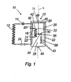
- FIG. 1 shows a heat cycle with an integrated condensation storage.
- the heat cycle 10 off FIG. 1 consists of an evaporator 12, a downstream in the direction of flow of the compressor 14, the output of which is connected to a capacitor 16 arranged in a condenser 16 capacitor.
- the condenser 18 (or condensation heat exchanger) includes an upper condensation heat exchanger section 20 and a lower condensation heat exchanger section 22 connected thereto.
- the outlet of the condenser 18 is connected to an expansion valve 24, the outlet of which is in turn connected to the evaporator 12.
- the components evaporator, compressor and expansion valve of the heat cycle 10 are known per se components and are not explained here.
- the storage tank 26 has the shape of a cylinder about the rotation axis x with a circular base.
- the two superimposed annular heat exchanger sections 20 and 22 of the capacitor 18 are arranged, which are also arranged rotationally symmetrical about the axis of rotation x except their connections.
- the two condensation heat exchanger sections 20 and 22, due to their peculiar formation, with which they cover a large proportion of the inner surface of the storage tank 26, a very large area.
- annular partition wall 28 is arranged, which is arranged rotationally symmetrical about the axis x at a small distance from the upper condensation heat exchanger section 20 and extends vertically.
- the distance between the upper condensation heat exchanger section 20 and the inner wall of the storage vessel 26 and the distance of the partition wall 28 from the upper condensation heat exchanger section 20 are comparatively small, preferably between 1 cm and 20 cm, preferably between 2 cm and 10 cm, so that a certain chimney effect is achieved in this annular area between the inner wall of the storage tank 26 and partition 28.
- the storage tank further includes a heating flow connection 30, which opens via a vertical pipe 32 with its opening 31 in the upper portion of the boiler 26, ie in a region above the partition wall 28.
- a central heating flow connection 34 in the central region of the boiler 26 is provided , between the upper heating flow connection 30 and the middle heating flow connection 34 , a mixing valve (not shown) can preferably be arranged, by means of which the flow temperature of the heating can be set individually.
- the storage tank 26 has a heating return connection 36, which is preferably large via a layer tube 38 Diameter, for example between 5 and 15 cm diameter is connected to the lower area of the storage tank.
- the connection of the layer tube 38 with the lower portion of the storage vessel 26 via many openings 40, wherein the heating water automatically enters through the opening 40 in the lower region of the storage tank 26, which corresponds to the temperature of the heating return.
- a layer tube for a heating return is known per se and is therefore not explained in detail.
- the storage tank 26 may still be provided a stainless steel coil 42 for a domestic water heating. It is also advantageous if an emptying opening 44 is provided on the floor for maintenance purposes.
- a flushing device 46 is provided in the upper region of the storage tank 26, which is connected via a flushing connection 48 with a concentric about the axis of rotation x extending annular tube, which has arranged above the condenser 18 and downwardly directed flushing openings 50.
- the upper condensing heat exchanger section 20 and the lower condensing heat exchanger section 22, which are connected to each other via a connecting line 21, occupy a large portion of the inner surface of the storage vessel 26.
- the condensation heat exchanger or condenser 18 is relative to the theoretical one required heat exchanger surface is greatly oversized, in particular at least by a factor of 2, preferably even by a factor of 3 and more. In this way, it is possible to optimally utilize the energies that can be transposed in the region of the capacitor 18 in the overtemperature range, in the condensation range and in the subcooling range, which greatly increases the effectiveness of the condensation accumulator.
- each element can preferably also be formed multiple or multiple parts.
- other features are optional, e.g. the subdivision of the condenser into an upper and a lower condensation heat exchanger section, and / or the shape of the condenser 18 and its arrangement in the storage vessel 26.
Landscapes
- Engineering & Computer Science (AREA)
- Mechanical Engineering (AREA)
- General Engineering & Computer Science (AREA)
- Physics & Mathematics (AREA)
- Thermal Sciences (AREA)
- Chemical & Material Sciences (AREA)
- Combustion & Propulsion (AREA)
- Water Supply & Treatment (AREA)
- Heat-Pump Type And Storage Water Heaters (AREA)
- Other Air-Conditioning Systems (AREA)
- Heat-Exchange Devices With Radiators And Conduit Assemblies (AREA)
Abstract
Description
- Die vorliegende Erfindung betrifft einen Kondensationsspeicher zur Verwendung in einem Wärmepumpenkreislauf und einen Wärmepumpenkreislauf mit einem Kondensationsspeicher.
- Wärmepumpensysteme umfassen üblicherweise einen Verdampfer und einen Kondensator, wobei inzwischen integrierte Kondensationsspeicher existieren, welche den Speicherkessel eines Heizungssystems bilden und in welchem Kondensationswärmetauscher des Wärmepumpenkreislaufs integriert ist.
- Das Problem bei herkömmlichen verdampferbasierten Wärmepumpensystemen besteht darin, dass die Vorlauftemperatur des Heizwassers begrenzt ist durch die Kondensationstemperatur des Fluids im Wärmepumpenkreislaufs. Daher muss zur Erzielung einer vernünftigen Vorlauftemperatur des Heizkreislaufes die Kondensationstemperatur des Wärmepumpenkreislaufs angehoben werden, was energetisch sehr ungünstig ist, oder man erzielt nur Vorlauftemperaturen die allenfalls für Fußbodenheizungen ausreichend ist.
- Es ist Aufgabe der Erfindung, einen Kondensationsspeicher für ein verdampferbasiertes Wärmepumpensystem zu schaffen, der bei geringer Kondensationstemperatur eine höhere Vorlauftemperatur des Heizwassers ermöglicht als bisher. Diese Aufgabe wird durch einen Kondensationsspeicher gemäß Anspruch 1 und einen Wärmepumpenkreislauf gemäß Anspruch 15 gelöst. vorteilhafte Weiterbildungen der Erfindung sind Gegenstand der Unteransprüche.
Der Kondensator in dem erfindungsgemäßen Kondensationsspeicher zeichnet sich darin aus, dass er beträchtlich überdimensioniert ist, so z.B. um den Faktor 2 größer ist, als es theoretisch gemäß nachfolgender Aufstellung erforderlich wäre. - Nachfolgend werden die Begriffe Wärmetauscher, Kondensationswärmetauscher und Kondensator synonym verwendet. In gleicher Weise werden die Begriffe Kessel und Speicherkessel synonym verwendet. Mit dem Ausdruck "Fluid" wird ein herkömmliches Kühl-/Wärmemittel eines Wärmepumpenkreislaufs bezeichnet.
- Die theoretisch benötigte Fläche eines Kondensators (oder Kondensationswärmetauschers) errechnet sich nach folgender Formel:

mit - A
- = Kontaktfläche des Wärmetauschers (m2)
- Q
- = Wärmefluss m · cp · dt Wärmeleistung (kJ/h · K)
- K
- = Wärmedurchgangszahl des Wärmetauschers
- m
- = Massestrom (l/h)
- dt
- = Temperaturdifferenz des Mediums vor/hinter Wärmetauscher (K)
- Δtm
- = mittlere Temperaturdifferenz zwischen dem Fluid und dem Heiz- wasser (K) in einem Gegenstromwärmetauscher nach folgender Formel: tm=( Tg- Tk)/ln( Tg/ TK), mit Tg = größere Differenz- temperatur zwischen den Medien an einer Seite des Wärmtauschers und Tk = kleinere Differenztemperatur zwischen den Medien an der anderen Seite des Wärmetauschers
- Cp
- = Spezifische Wärmekapazität von Wasser (4,182 k J/kgK)
- Mit dieser Formel wird in der Praxis die Fläche Wärmetauschers errechnet. Sie entspricht dem theoretischen Wert gemäß Anspruch 16.
- Vorzugsweise beträgt die gemäß der vorliegenden Erfindung verwendete Kondensationswärmetauscherfläche jedoch mindestens Faktor 2 mal diesem theoretischen Wert. Vorzugsweise ist die Fläche sogar mindestens um den Faktor 3, oder Faktor 4 bis Faktor 8 oder mehr größer als der entsprechende theoretische Wert.
- Man kann die Überdimensionierung des Kondensationswärmetauschers auch in anderer aber analoger Weise beschreiben. So sollte die Fläche des Wärmetauschers wenigstens 0,7 qm/ kW Heizleistung des Wärmepumpenkreislaufs betragen, vorzugsweise mehr als 0,8 qm/kW Heizleistung, insbesondere mehr als 1 qm/kW Heizleistung.
- Nachfolgend wird der im Kondensator abgreifbare Energiegehalt des Fluids betrachtet. In einem Kondensationsspeicher wird Energie durch ein Fluid bzw. Wärmeübertragungsmittel eingeführt, welches beispielsweise beim Eintritt in den Kondensator eine Temperatur von 82° C hat. Die Kondensationstemperatur liegt so beispielsweise bei 50° C und das Kondensat hat eine Temperatur von 45° C bei einer Außentemperatur von 16° C. Die im Rahmen der Entwärmung des Fluids und Kondensation erzielbaren Energieanteile liegen wie folgt:
- Übertemperatur 20 %,
- Kondensation 72 %,
- Unterkühlung 8 %.
- Durch die Überdimensionierung des Kondensationswärmetauschers wird nun sowohl der Übertemperaturanteil, d.h. der Bereich vom Eintritt des Fluids bis zum Erreichen der Kondensationstemperatur aufgrund der stark vergrößerten Kontaktfläche mit dem im Speicher befindlichen Heizwasser abgegriffen, wodurch zum einen der Übertemperaturenergieanteil von 20 % vollständig genutzt werden und zum anderen - und das ist wirklich das Revolutionäre an dem Erfindungskonzept - das Wasser im Heizungskessel über die Temperatur des Kondensationspunktes erwärmt werden kann. Diese 20% Übertemperaturenergieanteil werden vollständig zur Erhöhung der Vorlauftemperatur des Heiz- und/oder Bauchwassers genutzt.
- Es kann somit durch die Erfindung eine Vorlauftemperatur im Kessel erzielt werden kann, die höher liegt als der Kondensationspunkt des Fluids im Wärmepumpenkreislauf. Dies ist aus ökonomischer Sicht äußerst vorteilhaft, weil man bislang die Kondensationstemperatur im Kondensationswärmetauscher auf einen Punkt einstellen musste, der über der zu erzielenden Vorlauftemperatur lag, was energetisch sehr nachteilig ist. Denn je niedriger der Kondensationspunkt ist, desto wirtschaftlicher arbeitet die Anlage. Die Erhöhung des Kondensationspunktes wäre beispielsweise mit einem erhöhten Energieaufwand von 30% verbunden.
- Wenn man bislang einen niedrigeren Kondensationspunkt wählte, beispielsweise von 40 - 45 Grad C so führte das zu niedrigen Vorlauftemperaturen unterhalb des Kondensationspunktes, die allenfalls für Fußbodenheizungen ausreichend war.
- Mit der Erfindung ist der Kondensationspunkt nicht mehr der begrenzende Faktor für die Höhe der Vorlauftemperatur, sondern man kann durch die - nach bisherigen wirtschaftlichen Überlegungen völlig abwegige - starke Überdimensionierung des Wärmetauschers den Übertemperaturbereich zum Boosten er Vorlauftemperatur im Kessel nutzen.
- In gleicher Weise wird das Fluid nach der Kondensation in dem überdimensionierten Wärmetauscher noch lange im Wärmekontakt mit dem Heizwasser im Speicher weitergeführt, so dass auch der Unterkühlungsenergieanteil von 8 % weitgehend genutzt wird. Hieraus ergibt sich auch ein insgesamt wesentlich verbesserter Wirkungsgrad.
- Der verbesserte Wirkungsgrad wird insbesondere bei großen Kesseln erzielt, welche eine Größe von mindestens 200 1, vorzugsweise mindestens 350 1, und insbesondere größer als 500 1 haben. Diese erhebliche Größe des Speicherkessels hat den Vorteil, dass zum einen die Heizleistung durch den überdimensionierten Wärmetauscher besser, d.h. mit geringeren Verlusten in das im Kessel befindliche Heizungs- und Brauchwasser übertragen werden kann. Zum anderen erlaubt der große Kesselinhalt ein relativ langes Aufrechterhalten der Temperatur des im Kessel gespeicherten Heizungs- und Brauchwassers und somit zum Beispiel eine Abschaltung der Wärmepumpe zu Stromspitzenzeiten.
- Vorzugsweise ist der Kessel nicht nur für die Brauchwassererwärmung sondern für die Brauchwassererwärmung als auch für die Heizung vorgesehen. Auf diese Weise kann das große Volumen des im Kessel zwischen Kesselwand und Wärmetauscher befindlichen Heizungs- und Brauchwassers gut für eine effektive Wärmeübertragung genutzt werden. Zum anderen wird nur ein Kessel für die Heizungswasser- und Brauchwasseraufbereitung benötigt.
- Insbesondere der Übertemperaturenergieanteil wird bedeutend besser genutzt, wenn im oberen Bereich des Speichers eine Einrichtung vorgesehen ist, die den Wärmeaustausch zwischen dem Kondensationswärmetauscher und dem Wasser im Kessel so steuert, dass die Differenztemperatur zwischen dem Kesselwasser und dem Fluid im Kondensationswärmetauscher herabgesetzt wird. Hierfür wird der Zugang des Wassers im Kessel zu dem Kondensationswärmetauscher begrenzt. Denn wenn weniger Wasser in Kontakt mit dem Kondensationswärmetauscher kommt, wird dieses stärker erwärmt und das Fluid im Kondensationswärmetauscher kühlt nicht so schnell ab. Im Endeffekt wird hierbei wiederum eine stärkere Erwärmung des Wassers im Kessel erreicht, die wiederum eine wesentliche Erhöhung der Vorlauftemperatur ermöglicht.
- Die Einrichtung zur Verringerung der Strömungsmenge an Kesselwasser, die in Kontakt mit dem Wärmtauscher kommt, kann konstruktiv durch den Kondensationswärmetauscher selber realisiert werden oder konstruktiv in der Anordnung des Wärmetauschers im Kessel, z.B. durch die dichte Anordnung zumindest des Übertemperaturbereichs des Wärmetauschers nahe den Wänden des Speicherkessels. Der Übertemperaturbereich des Wärmetauschers ist derjenige, in welchem die Temperatur des Fluids im Kondensator oberhalb der Kondensationstemperatur liegt.
- Vorzugsweise ist die Einrichtung in konstruktiv einfacher Weise durch Trennwände gebildet, die sich vorzugsweise in einem definierten Abstand zu den Kondensationswärmetauscherflächen, vorzugsweise senkrecht erstrecken. Auf diese Weise strömt das Wasser zwischen diesen Trennwänden und dem Kondensationswärmetauscher in Art eines Kamineffekts langsam nach oben, was den Wärmeaustausch zwischen dem Wärmetauscher und dem Heizwasser im Kessel herabsetzt und zu einer starken Erwärmung der Wassertemperatur im Kessel über die Kondensationstemperatur des Fluids führt. Eine derartige Anordnung mit Trennwänden ist konstruktiv einfach zu realisieren und sehr effektiv.
- Vorzugsweise kann oben oberhalb der Trennwände und unterhalb der Trennwände ein normaler Austausch des Wassers, vorzugsweise über den gesamten Querschnitt des Kessels stattfinden.
- Die Öffnung für den Vorlauftemperatur-Anschluss eines Heizwasserkreislaufs mündet vorzugsweise im oberen Bereich der Tennwand oder oberhalb der Trennwand in den Kessel, wo die Wassertemperatur über die Kondensationstemperatur erwärmt ist.
- Um eine große flächige Anordnung des Kondensationswärmetauschers im Kessel zu realisieren, ist es vorteilhaft, wenn der Kondensationswärmetauscher ringförmig parallel und in einem geringen Abstand zu den Innenwänden des Kessels angeordnet ist. Der Abstand sollte vorzugsweise zwischen 2 und 20 cm liegen.
- In dem, z.B. ringförmigen, Kondensationswärmetauscher ist das Fluid vorzugsweise in sich schraubenfömig nach unten erstreckenden Strömungskanälen, z.B. Rohren geführt, so dass es den Kessel langsam in dem Kondensator von oben nach unten durchströmt, während das Wasser im Gegenstrom durch die Aufheizung im Kessel von unten nach oben strömt. Die Strömungskanäle können mit Flächenstrukturen zur Verbesserung des Wärmeaustauschs in an sich bekannter Weise versehen sein.
- Um eine insbesondere gute Energieausnutzung des Übertemperaturanteils und des Unterkühlungsanteils zu gewährleisten ist es vorteilhaft, wenn der Kondensationswärmetauscher vertikale Abschnitte aufweist, die miteinander verbunden sind, wobei im oberen Abschnitt der Übertemperaturanteil und Kondensationsanteil und im unteren Anteil der Unterkühlungsanteil umgesetzt wird. Im unteren Teil kann auch noch ein Teil der Kondensationswärme umgesetzt werden.
- Besonders vorteilhaft ist es, wenn der Kessel in der Form eines kreisrunden Zylinders ausgebildet ist und der Wärmetauscher ringförmig an den Innenwänden einen geringen Abstand von wenigen Zentimetern angeordnet ist und weiterhin an der Innenseite des Wärmetauschers eine ringförmige Trennwand ebenfalls mit einem Abstand von wenigen Zentimetern angeordnet ist.
- Der Abstand zwischen dem Kondensationswärmetauscher und der Innenwand des Kessels als auch zwischen dem Kondensationswärmetauscher und der Trennwand sollte zwischen 2 und 20 cm, vorzugsweise zwischen 1 und 20 cm, vorzugsweise zwischen 2 und 10 cm liegen.
- Die Fläche des Kondensationswärmetauschers sollte im Falle der Anordnung des Kondensators bzw. Kondensationswärmetauschers in einem geringen Abstand von der Innenwand des Kessels wenigstens 50 %, vorzugsweise wenigstens 60 % der Innenfläche der vertikalen Kesselwand überdecken.
- Um eine gewünschte Vorlauftemperatur einstellen zu können, sollte der Kessel mindestens einen Heizungsvorlaufanschluss in seinem oberen Bereich und einen Heizungsvorlaufanschluss in seinem mittleren Bereich aufweisen. An diese beiden Anschlüsse kann dann beispielsweise eine Mischarmatur angeschlossen werden, durch welche eine beliebige Vorlauftemperatur zwischen dem Mittelabgriff und dem oberen Abgriff eingestellt werden kann.
- Weiterhin hat der Kondensationsspeicher vorzugsweise einen Heizungsrücklaufanschluss, der in ein an sich bekanntes Schichtrohr mündet, welches vertikal in dem Kessel verläuft und mehrere Austritte in unterschiedlicher Höhe des Kessels aufweist. Ein derartiges Schichtrohr hat einen sehr großen Durchmesser von beispielsweise 5 - 15 cm, vorzugsweise 7-10 cm und trägt dazu bei, dass das Wasser durch einen Austritt in einer solchen Höhe in den Kessel einströmt, in welcher Höhe die gleiche Temperatur wie die Rücklauftemperatur herrscht. Auf diese Weise wird vermieden, dass das kühlere Wasser von ganz unten im Kessel immer wieder nach oben aufgewirbelt wird.
- Vorzugsweise ist im oberen Bereich des Speicherkessels oberhalb des Kondensationswärmetauschers eine Spüleinrichtung angeordnet. Die Spüleinrichtung ist vorzugsweise als Ringrohr mit nach unten ausgerichteten Spülöffnungen ausgebildet. Durch sie kann eine Reinigungsflüssigkeit oder auch Wasser mit Hochdruck auf den Kondensationswärmetauscher gesprüht werden, um diesen von Verunreinigungen zu reinigen.
- Wenn der Kondensationsspeicher auch zur Brauchwasseraufbereitung genutzt werden soll, ist es vorteilhaft, in dem Kesselinneren eine sich vertikal erstreckende Rohrwendel für eine Brauchwassererwärmung vorzusehen. Der gesamte Kessel kann natürlich auch statt für Erwärmung des Wassers für einen Heizkreislauf auch zur Wassererwärmung für einen Brauchwasserkreislauf verwendet werden.
- Der Verdampfer des Wärmekreislaufes kann jeder übliche Verdampfer sein, der vorzugsweise im Außenbereich eines Gebäudes angeordnet wird.
- Die Erfindung wird nun beispielsweise anhand der schematischen Zeichnung beschrieben. Es soll hierbei klargestellt sein, dass die technischen Merkmale der Ausführungsform nicht alle gleichzeitig realisiert sein müssen, sondern optional sind, soweit sie sich nicht gegenseitig bedingen, was jedoch ausdrücklich in der Figurenbeschreibung zum Ausdruck gebracht wird.
-
Figur 1 zeigt einen Wärmekreislauf mit einem integrierten Kondensationsspeicher. - Der Wärmekreislauf 10 aus
Figur 1 besteht aus einem Verdampfer 12, einem in Flussrichtung des Fluids folgenden Kompressor 14, dessen Ausgang mit einem in einem Kondensationsspeicher 16 angeordneten Kondensator 18 verbunden ist. Der Kondensator 18 (bzw. Kondensationswärmetauscher) enthält einen oberen Kondensationswärmetauscherabschnitt 20, und einen mit diesem verbundenen unteren Kondensationswärmetauscherabschnitt 22. Der Ausgang des Kondensators 18 ist mit einem Expansionsventil 24 verbunden, dessen Ausgang wiederum mit dem Verdampfer 12 verbunden ist. Die Komponenten Verdampfer, Kompressor und Expansionsventil des Wärmekreislaufs 10 sind an sich bekannte Komponenten und werden hier nicht näher erläutert. - Neu ist der in einem Speicherkessel 26 integrierte Kondensator 18, der zusammen mit dem Speicherkessel 26 einen integrierten Kondensationsspeicher 16 bildet.
- Der Speicherkessel 26 hat die Form eines Zylinders um die Rotationsachse x mit kreisförmiger Grundfläche. In einem geringen Abstand von der Innenwand des Kessels sind die zwei übereinander angeordneten ringförmigen Wärmetauscherabschnitte 20 und 22 des Kondensators 18 angeordnet, die ausgenommen ihrer Anschlüsse ebenfalls rotationssymmetrisch um die Rotationsachse x angeordnet sind,. Die beiden Kondensationswärmetauscherabschnitte 20 und 22 haben aufgrund ihrer eigenartigen Ausbildung, mit der sie einen großen Anteil der Innenfläche des Speicherkessels 26 abdecken, eine sehr große Fläche.
- Innerhalb des oberen ringförmigen Kondensationswärmetauscherabschnitts 20 ist eine ringförmige Trennwand 28 angeordnet, die rotationssymmetrisch um die Achse x in einem geringen Abstand von dem oberen Kondensationswärmetauscherabschnitt 20 angeordnet ist und sich senkrecht erstreckt. Der Abstand zwischen dem oberen Kondensationswärmetauscherabschnitt 20 und der Innenwand des Speicherkessels 26 als auch der Abstand der Trennwand 28 von dem oberen Kondensationswärmetauscherabschnitt 20 sind vergleichsweise gering, vorzugsweise zwischen 1 cm und 20 cm, vorzugsweise zwischen 2 cm und 10 cm, so dass eine gewisse Kaminwirkung in diesem ringförmigen Bereich zwischen Innenwand des Speicherkessels 26 und Trennwand 28 erzielt wird. Hierdurch ist der Wärmeaustausch des oberen Kondensationswärmetauscherabschnitts 20 mit dem im Speicherkessel vorhandenen Heizungswasser geringer, weil die mittlere Temperaturdifferenz zwischen den Ein/Ausströmtemperaturen des Fluids und des Heizwassers geringer gehalten werden, so dass eine bessere, insbesondere vollständige, Ausnutzung der Energie im Überhitzungsbereich zur Erhöhung der Vorlauftemperatur bzw. des Wassers im Kessel über den Kondensationspunkt hinaus realisiert wird. Der Speicherkessel enthält weiterhin einen Heizungsvorlaufanschluss 30, der über ein senkrechtes Rohr 32 mit seiner Öffnung 31 in den oberen Abschnitt des Kessels 26 mündet, d.h. in einen Bereich oberhalb der Trennwand 28. Des Weiteren ist ein mittlerer Heizungsvorlaufanschluss 34 im mittleren Bereich des Kessels 26 vorgesehen. Zwischen dem oberen Heizungsvorlaufanschluss 30 und dem mittleren Heizungsvorlaufanschluss 34 kann vorzugsweise eine Mischarmatur (nicht dargestellt) angeordnet werden, durch welche die Vorlauftemperatur der Heizung individuell eingestellt werden kann. Des Weiteren verfügt der Speicherkessel 26 über einen Heizungsrücklaufanschluss 36, der vorzugsweise über ein Schichtrohr 38 großen Durchmessers, z.B. zwischen 5 und 15 cm Durchmesser mit dem unteren Bereich des Speicherkessels verbunden ist. Die Verbindung des Schichtrohrs 38 mit dem unteren Bereich des Speicherkessels 26 erfolgt über viele Öffnungen 40, wobei das Heizwasser selbsttätig durch die Öffnung 40 in den unteren Bereich des Speicherkessels 26 eintritt, die der Temperatur des Heizungsrücklaufs entspricht. Ein derartiges Schichtrohr für einen Heizungsrücklauf ist an sich bekannt und wird daher nicht näher erläutert.
- Optional kann in dem Speicherkessel 26 noch eine Edelstahlwendel 42 für eine Brauchwassererwärmung vorgesehen sein. Ebenso ist es vorteilhaft, wenn am Boden eine Entleerungsöffnung 44 für Wartungszwecke vorgesehen ist.
- Vorzugsweise ist im oberen Bereich des Speicherkessels 26 eine Spüleinrichtung 46 vorgesehen, die über einen Spülanschluss 48 mit einem konzentrisch um die Rotationsachse x verlaufenden Ringrohr verbunden ist, welches über dem Kondensator 18 angeordnete und nach unten gerichtete Spülöffnungen 50 aufweist.
- Durch die Betätigung der Entleerungsöffnung 44 und der Spüleinrichtung 46 lässt sich mit geringem Aufwand eine einfache Reinigung des Heizungskessels vornehmen.
- Wie auf dem Bild zu sehen ist, nehmen der obere Kondensationswärmetauscherabschnitt 20 und der untere Kondensationswärmetauscherabschnitt 22, die über eine Verbindungsleitung 21 miteinander verbunden sind, einen großen Anteil der Innenfläche des Speicherkessels 26 ein. Dies kommt daher, dass der Kondensationswärmetauscher oder Kondensator 18 relativ zur theoretisch erforderlichen Wärmetauscherfläche stark überdimensioniert ist, insbesondere mindestens um den Faktor 2, vorzugsweise sogar um den Faktor 3 und mehr. Auf diese Weise ist es möglich, die im Bereich des Kondensators 18 übertragbaren Energien im Übertemperaturbereich, im Kondensationsbereich und im Unterkühlungsbereich optimal auszuschöpfen, was die Effektivität des Kondensationsspeichers stark heraufsetzt.
- Insbesondere durch die Anordnung der oberen ringförmigen Trennwand 28 auf der Innenseite des oberen Kondensationswärmetauscherabschnitts 20 ist es möglich, den Wärmeaustausch mit dem im Speicherkessel 26 vorhandenen Wasser aufgrund einer Verringerung der mittleren Temperaturdifferenz (Siehe Seite 1) herabzusetzen, so dass die Energieausbeute gerade im Übertemperaturbereich des Kondensators 18 erheblich verbessert wird. Die vorliegende Erfindung ist nicht auf das dargestellte Ausführungsbeispiel beschränkt, sondern kann innerhalb des Schutzbereichs der beigefügten Ansprüche variiert werden.
- Es wird weiterhin darauf hingewiesen, dass aus Gründen der Klarheit alle Elemente des Wärmekreislaufs und der Elemente des Kondensationsspeichers einfach dargestellt sind. Jedes Element kann vorzugsweise auch mehrfach oder mehrteilig ausgebildet sein. Darüber hinaus sind weitere Merkmale optional, z.B. die Unterteilung des Kondensators in einen oberen und einen unteren Kondensationswärmetauscherabschnitt, und/oder die Form des Kondensators 18 und dessen Anordnung im Speicherkessel 26.
Claims (15)
- Kondensationsspeicher (16) zur Verwendung in einem Wärmepumpenkreislauf, umfassend einen Speicherkessel (26) für Wasser eines Heizungs- oder Brauchwassersystems,
einen in dem Speicherkessel angeordneten und von dem Kühlmittel des Wärmepumpenkreislaufes durchströmten Kondensationswärmetauscher (18), welcher Speicherkessel (26) eine Größe von 200 bis 10001 aufweist, und bei dem die Fläche des Kondensationswärmetauschers wenigstens 0,7 qm/kW Heizleistung beträgt. - Kondensationsspeicher (16) nach Anspruch 1, dadurch gekennzeichnet, dass der Speicherkessel eine Größe von wenigstens 3501, insbesondere wenigstens 5001 aufweist.
- Kondensationsspeicher (16) nach Anspruch 1 oder 2, dadurch gekennzeichnet, dass in dem Bereich des Kondensationswärmetauschers, in welchem das Fluid eine Temperatur oberhalb der Kondensationstemperatur aufweist, eine Einrichtung (28) vorgesehen ist, die den Zugang des Wassers im Speicherkessel (26) zu dem Kondensationswärmetauscher (18) begrenzt.
- Kondensationsspeicher (16) nach Anspruch 3, dadurch gekennzeichnet, dass die Einrichtung durch wenigstens eine Trennwand (28) gebildet ist, welche insbesondere in einem definierten Abstand zum Kondensationswärmetauscher (18) angeordnet ist.
- Kondensationsspeicher nach Anspruch 3 oder 4, dadurch gekennzeichnet, dass die Öffnung (31) des der Vorlauftemperatur-Anschlusses (30) im oberen Bereich oder oberhalb der Einrichtung (28) angeordnet ist.
- Kondensationsspeicher (16) nach einem der vorhergehenden Ansprüche, dadurch gekennzeichnet
dass der Kondensationswärmetauscher (18) konzentrisch um die Kesselachse (x) im Randbereich des Kessels angeordnet ist. - Kondensationsspeicher (16) nach Anspruch 5 und 6, dass der Kondensationswärmetauscher (18) zwischen der Kesselwand und der Trennwand (28) angeordnet ist.
- Kondensationsspeicher (16) nach Anspruch 6 oder 7, dass der Kondensationswärmetauscher (18) ringförmig ausgebildet ist.
- Kondensationsspeicher (16) nach Anspruch 8, dass sich der Kondensationswärmetauscher (18) sich über wenigstens 50%, vorzugsweise wenigstens 60% der Fläche der vertikalen Kesselwand erstreckt.
- Kondensationsspeicher (16) nach einem der vorhergehenden Ansprüche, dadurch gekennzeichnet, dass der Kessel (26) mindestens einen oberen Heizungsvorlauf-Anschluss (30) im oberen Bereich und einen mittleren Heizungsvorlauf-Anschluss (34) im mittleren Bereich des Kessels (26) aufweist.
- Kondensationsspeicher (16) nach Anspruch 10, dadurch gekennzeichnet, dass die beiden Heizungsvorlauf-Anschlüsse (30, 34) mit einer Mischarmatur zum Einstellen einer gewünschten Vorlauftemperatur verbunden sind.
- Kondensationsspeicher (16) nach einem der vorhergehenden Ansprüche, dadurch gekennzeichnet, dass der Heizungsrücklauf-Anschluss (36) in ein Schichtrohr (38) mündet, das vertikal in dem Kessel (26) verläuft und mehrere Austritte (40) in unterschiedlicher Höhe des Kessels aufweist.
- Kondensationsspeicher (16) nach einem der vorhergehenden Ansprüche, dadurch gekennzeichnet, dass der Innenraum des Kessels (26) mit einem Heizungskreislauf verbunden ist, und dass innerhalb des Kessels eine sich vertikal erstreckende Rohrwendel (42) für eine Brauchwassererwärmung angeordnet ist.
- Wärmepumpenkreislauf (10) umfassend einen Verdampfer (12), einen Kompressor (14), ein Expansionsventil (24) und einen Kondensationsspeicher (16) nach einem der vorhergehenden Ansprüche.
- Wärmepumpenkreislauf (10) nach Anspruch 14, dadurch gekennzeichnet, dass die Größe der Fläche des Kondensationswärmetauschers (18) in dem Kondensationsspeicher (16) wenigstens dem zweifachen, insbesondere mehr als dem Dreifachen des theoretischen Wertes für die notwendige Fläche des Wärmepumpenkreislaufs entspricht.
Priority Applications (1)
| Application Number | Priority Date | Filing Date | Title |
|---|---|---|---|
| DE202010013659U DE202010013659U1 (de) | 2009-07-27 | 2010-07-23 | Kondensationsspeicher in einem Wärmepumpenkreislauf |
Applications Claiming Priority (1)
| Application Number | Priority Date | Filing Date | Title |
|---|---|---|---|
| DE102009034879A DE102009034879A1 (de) | 2009-07-27 | 2009-07-27 | Kondensationsspeicher in einem Wärmepumpenkreislauf |
Publications (3)
| Publication Number | Publication Date |
|---|---|
| EP2295889A2 true EP2295889A2 (de) | 2011-03-16 |
| EP2295889A3 EP2295889A3 (de) | 2012-04-25 |
| EP2295889B1 EP2295889B1 (de) | 2015-04-22 |
Family
ID=42668452
Family Applications (1)
| Application Number | Title | Priority Date | Filing Date |
|---|---|---|---|
| EP10170652.1A Not-in-force EP2295889B1 (de) | 2009-07-27 | 2010-07-23 | Wärmepumpenkreislauf mit einem Kondensationsspeicherkessel |
Country Status (2)
| Country | Link |
|---|---|
| EP (1) | EP2295889B1 (de) |
| DE (2) | DE102009034879A1 (de) |
Cited By (3)
| Publication number | Priority date | Publication date | Assignee | Title |
|---|---|---|---|---|
| EP2860469A1 (de) * | 2013-10-11 | 2015-04-15 | Nederlandse Organisatie voor toegepast -natuurwetenschappelijk onderzoek TNO | Warmwasserbereiter |
| EP3037743A1 (de) * | 2014-12-23 | 2016-06-29 | ROTEX Heating Systems GmbH | Heizsystem für brauchwasser |
| EP4043801A1 (de) * | 2021-02-10 | 2022-08-17 | Daikin Industries, Ltd. | System zur erzeugung von wärme für brauchwarmwasser oder zentralheizung |
Families Citing this family (3)
| Publication number | Priority date | Publication date | Assignee | Title |
|---|---|---|---|---|
| DE102012017343B4 (de) * | 2012-08-29 | 2015-06-11 | Johannes Georg Mehlig | Dezentraler Warmwasser-Bereiter/ -Speicher |
| EP2980492A1 (de) * | 2014-07-29 | 2016-02-03 | Johannes Paul Ennemoser | Druckloser thermischer systemspeicher |
| EP3892925B1 (de) | 2020-04-08 | 2024-02-14 | Vattenfall AB | Heizsystem, verfahren, computerprogramm, computerlesbares medium und steuervorrichtung |
Family Cites Families (12)
| Publication number | Priority date | Publication date | Assignee | Title |
|---|---|---|---|---|
| GB1571659A (en) * | 1976-10-21 | 1980-07-16 | Dec Int | Combined storage tank and heat exchanger unit and a water heating system incorporating a said unit |
| AU3869778A (en) * | 1977-08-12 | 1980-02-14 | Mueller P Company | Condenser |
| DE3032953A1 (de) * | 1979-09-14 | 1981-04-02 | Pumpenfabrik Ernst Vogel, Stockerau, Niederösterreich | Waermepumpanlage |
| DE3142536A1 (de) * | 1981-10-27 | 1983-05-05 | Bosch-Siemens Hausgeräte GmbH, 7000 Stuttgart | Waermepumpe, insbesondere brauchwasser-waermepumpe |
| DE19731351A1 (de) * | 1997-07-22 | 1999-01-28 | Robionek Hans Joachim | Speicherwassererwärmer |
| DE20207691U1 (de) * | 2002-05-16 | 2002-09-12 | Möller, Hans, Prof. Dipl.-Ing., 44627 Herne | Multivalente Elektro-Diesel-Wärmepumpe |
| DE102004018034B4 (de) * | 2004-04-14 | 2014-07-24 | Stiebel Eltron Gmbh & Co. Kg | Verfahren zur Einschaltung einer Wärmepumpe in Verbindung mit einem Brauchwasserspeicher für Wärmepumpen |
| DE102005001511A1 (de) * | 2005-01-13 | 2006-07-27 | Paradigma Energie- Und Umwelttechnik Gmbh & Co. Kg | Thermische Schichtleiteinrichtung für Oberflächenwärmetauscher |
| DE102005051663A1 (de) * | 2005-10-28 | 2007-05-03 | Robert Kremer | Heizwasser-Schichtenspeicher mit integriertem Durchfluss-Trinkwassererwärmer aus Membran-Ovalrohr |
| DE202006009009U1 (de) * | 2006-06-08 | 2007-10-18 | Dietz, Erwin | Wärmeübertrager |
| JP2008138991A (ja) * | 2006-12-05 | 2008-06-19 | Sanyo Electric Co Ltd | 加熱タンク及び貯湯タンク |
| DE102008021804A1 (de) * | 2008-04-03 | 2009-10-08 | WISAG Gebäude- und Industrieservice Nord-West GmbH | Heizvorrichtung |
-
2009
- 2009-07-27 DE DE102009034879A patent/DE102009034879A1/de not_active Withdrawn
-
2010
- 2010-07-23 EP EP10170652.1A patent/EP2295889B1/de not_active Not-in-force
- 2010-07-23 DE DE202010013659U patent/DE202010013659U1/de not_active Expired - Lifetime
Non-Patent Citations (1)
| Title |
|---|
| None |
Cited By (7)
| Publication number | Priority date | Publication date | Assignee | Title |
|---|---|---|---|---|
| EP2860469A1 (de) * | 2013-10-11 | 2015-04-15 | Nederlandse Organisatie voor toegepast -natuurwetenschappelijk onderzoek TNO | Warmwasserbereiter |
| WO2015053630A1 (en) * | 2013-10-11 | 2015-04-16 | Nederlandse Organisatie Voor Toegepast-Natuurwetenschappelijk Onderzoek Tno | Water heater |
| EP3037743A1 (de) * | 2014-12-23 | 2016-06-29 | ROTEX Heating Systems GmbH | Heizsystem für brauchwasser |
| EP4043801A1 (de) * | 2021-02-10 | 2022-08-17 | Daikin Industries, Ltd. | System zur erzeugung von wärme für brauchwarmwasser oder zentralheizung |
| WO2022172867A1 (en) * | 2021-02-10 | 2022-08-18 | Daikin Industries, Ltd. | System for producing heat for domestic hot water or central heating |
| JP2024508107A (ja) * | 2021-02-10 | 2024-02-22 | ダイキン工業株式会社 | 家庭用温水またはセントラルヒーティングのための熱を生成するシステム |
| JP7574461B2 (ja) | 2021-02-10 | 2024-10-28 | ダイキン工業株式会社 | 家庭用温水またはセントラルヒーティングのための熱を生成するシステム |
Also Published As
| Publication number | Publication date |
|---|---|
| EP2295889A3 (de) | 2012-04-25 |
| DE102009034879A1 (de) | 2011-02-10 |
| DE202010013659U1 (de) | 2010-12-16 |
| EP2295889B1 (de) | 2015-04-22 |
Similar Documents
| Publication | Publication Date | Title |
|---|---|---|
| EP2295889B1 (de) | Wärmepumpenkreislauf mit einem Kondensationsspeicherkessel | |
| EP0099875B1 (de) | Vorrichtung zur Erwärmung von Heizungswasser und von Brauchwasser | |
| AT510440B1 (de) | Fluidspeicher | |
| AT508481B1 (de) | Verfahren zur erwärmung von brauchwasser | |
| DE102010005992A1 (de) | Speicher zum temperaturgeschichteten Speichern von warmen Flüssigkeiten unterschiedlicher Temperatur | |
| DE19707184B4 (de) | Warmwasserspeicher | |
| DE102010044535B4 (de) | Warmwasserbereitungsanlage und Verfahren zum Betreiben einer Warmwasserbereitungsanlage | |
| EP3705789B1 (de) | Wasserversorgungssystem und verfahren zum betreiben eines solchen | |
| DE102008059544A1 (de) | Brauchwassererwärmer, Brauchwasserversorgungssystem mit einem Brauchwassererwärmer sowie Verfahren zu deren Betrieb | |
| DE202013006209U1 (de) | Mischvorrichtung | |
| DE202006016100U1 (de) | Solarkollektorsystem | |
| EP3502606B1 (de) | Vorrichtung zur bereitstellung von heiz- und/oder brauchwarmwasser | |
| AT518182B1 (de) | Vorrichtung zum Erwärmen von Brauchwasser | |
| DE202013001469U1 (de) | Brauchwasser-Kombispeicher | |
| EP2815196A2 (de) | Wärmetauscher für eine heizungsanlage oder ein wärmeversorgungssystem | |
| EP1724415A2 (de) | Geregelter Zwei-Zonen-Pufferspeicher für frische Trinkwassererwärmung | |
| DE102018221410A1 (de) | Heizeinrichtung für Wasser | |
| DE102010018086A1 (de) | Wärmeübertragungseinrichtung | |
| EP4636319A1 (de) | Vorrichtung zur erwärmung von brauchwarmwasser | |
| DE102008018705A1 (de) | Pufferspeicher | |
| DE3024652A1 (de) | Fernheiz-warmwasserbereiter | |
| DE3227925A1 (de) | Heizungsanlage | |
| EP4616126A1 (de) | Warmwasserstation | |
| DE102006002727A1 (de) | Schichtenwärmespeichervorrichtung und Verfahren zur Warmwasserbereitung | |
| AT517021A1 (de) | Wärmetausch-Einrichtung |
Legal Events
| Date | Code | Title | Description |
|---|---|---|---|
| PUAI | Public reference made under article 153(3) epc to a published international application that has entered the european phase |
Free format text: ORIGINAL CODE: 0009012 |
|
| AK | Designated contracting states |
Kind code of ref document: A2 Designated state(s): AL AT BE BG CH CY CZ DE DK EE ES FI FR GB GR HR HU IE IS IT LI LT LU LV MC MK MT NL NO PL PT RO SE SI SK SM TR |
|
| AX | Request for extension of the european patent |
Extension state: BA ME RS |
|
| PUAL | Search report despatched |
Free format text: ORIGINAL CODE: 0009013 |
|
| AK | Designated contracting states |
Kind code of ref document: A3 Designated state(s): AL AT BE BG CH CY CZ DE DK EE ES FI FR GB GR HR HU IE IS IT LI LT LU LV MC MK MT NL NO PL PT RO SE SI SK SM TR |
|
| AX | Request for extension of the european patent |
Extension state: BA ME RS |
|
| RIC1 | Information provided on ipc code assigned before grant |
Ipc: F24H 4/04 20060101AFI20120322BHEP |
|
| 17P | Request for examination filed |
Effective date: 20121025 |
|
| 17Q | First examination report despatched |
Effective date: 20130708 |
|
| REG | Reference to a national code |
Ref country code: DE Ref legal event code: R079 Ref document number: 502010009379 Country of ref document: DE Free format text: PREVIOUS MAIN CLASS: F24H0004040000 Ipc: F25B0030020000 |
|
| RIC1 | Information provided on ipc code assigned before grant |
Ipc: F28D 20/00 20060101ALI20140904BHEP Ipc: F24H 4/04 20060101ALI20140904BHEP Ipc: F25B 30/02 20060101AFI20140904BHEP Ipc: F28G 9/00 20060101ALI20140904BHEP |
|
| GRAP | Despatch of communication of intention to grant a patent |
Free format text: ORIGINAL CODE: EPIDOSNIGR1 |
|
| INTG | Intention to grant announced |
Effective date: 20141117 |
|
| GRAS | Grant fee paid |
Free format text: ORIGINAL CODE: EPIDOSNIGR3 |
|
| GRAA | (expected) grant |
Free format text: ORIGINAL CODE: 0009210 |
|
| AK | Designated contracting states |
Kind code of ref document: B1 Designated state(s): AL AT BE BG CH CY CZ DE DK EE ES FI FR GB GR HR HU IE IS IT LI LT LU LV MC MK MT NL NO PL PT RO SE SI SK SM TR |
|
| REG | Reference to a national code |
Ref country code: GB Ref legal event code: FG4D Free format text: NOT ENGLISH |
|
| REG | Reference to a national code |
Ref country code: CH Ref legal event code: EP |
|
| REG | Reference to a national code |
Ref country code: AT Ref legal event code: REF Ref document number: 723472 Country of ref document: AT Kind code of ref document: T Effective date: 20150515 |
|
| REG | Reference to a national code |
Ref country code: IE Ref legal event code: FG4D Free format text: LANGUAGE OF EP DOCUMENT: GERMAN |
|
| REG | Reference to a national code |
Ref country code: DE Ref legal event code: R096 Ref document number: 502010009379 Country of ref document: DE Effective date: 20150603 |
|
| REG | Reference to a national code |
Ref country code: NL Ref legal event code: VDEP Effective date: 20150422 |
|
| REG | Reference to a national code |
Ref country code: LT Ref legal event code: MG4D |
|
| PG25 | Lapsed in a contracting state [announced via postgrant information from national office to epo] |
Ref country code: NL Free format text: LAPSE BECAUSE OF FAILURE TO SUBMIT A TRANSLATION OF THE DESCRIPTION OR TO PAY THE FEE WITHIN THE PRESCRIBED TIME-LIMIT Effective date: 20150422 |
|
| PG25 | Lapsed in a contracting state [announced via postgrant information from national office to epo] |
Ref country code: PT Free format text: LAPSE BECAUSE OF FAILURE TO SUBMIT A TRANSLATION OF THE DESCRIPTION OR TO PAY THE FEE WITHIN THE PRESCRIBED TIME-LIMIT Effective date: 20150824 Ref country code: NO Free format text: LAPSE BECAUSE OF FAILURE TO SUBMIT A TRANSLATION OF THE DESCRIPTION OR TO PAY THE FEE WITHIN THE PRESCRIBED TIME-LIMIT Effective date: 20150722 Ref country code: LT Free format text: LAPSE BECAUSE OF FAILURE TO SUBMIT A TRANSLATION OF THE DESCRIPTION OR TO PAY THE FEE WITHIN THE PRESCRIBED TIME-LIMIT Effective date: 20150422 Ref country code: HR Free format text: LAPSE BECAUSE OF FAILURE TO SUBMIT A TRANSLATION OF THE DESCRIPTION OR TO PAY THE FEE WITHIN THE PRESCRIBED TIME-LIMIT Effective date: 20150422 Ref country code: FI Free format text: LAPSE BECAUSE OF FAILURE TO SUBMIT A TRANSLATION OF THE DESCRIPTION OR TO PAY THE FEE WITHIN THE PRESCRIBED TIME-LIMIT Effective date: 20150422 Ref country code: ES Free format text: LAPSE BECAUSE OF FAILURE TO SUBMIT A TRANSLATION OF THE DESCRIPTION OR TO PAY THE FEE WITHIN THE PRESCRIBED TIME-LIMIT Effective date: 20150422 |
|
| PGFP | Annual fee paid to national office [announced via postgrant information from national office to epo] |
Ref country code: DE Payment date: 20150728 Year of fee payment: 6 |
|
| PG25 | Lapsed in a contracting state [announced via postgrant information from national office to epo] |
Ref country code: GR Free format text: LAPSE BECAUSE OF FAILURE TO SUBMIT A TRANSLATION OF THE DESCRIPTION OR TO PAY THE FEE WITHIN THE PRESCRIBED TIME-LIMIT Effective date: 20150723 Ref country code: IS Free format text: LAPSE BECAUSE OF FAILURE TO SUBMIT A TRANSLATION OF THE DESCRIPTION OR TO PAY THE FEE WITHIN THE PRESCRIBED TIME-LIMIT Effective date: 20150822 Ref country code: LV Free format text: LAPSE BECAUSE OF FAILURE TO SUBMIT A TRANSLATION OF THE DESCRIPTION OR TO PAY THE FEE WITHIN THE PRESCRIBED TIME-LIMIT Effective date: 20150422 |
|
| PGFP | Annual fee paid to national office [announced via postgrant information from national office to epo] |
Ref country code: AT Payment date: 20150722 Year of fee payment: 6 |
|
| REG | Reference to a national code |
Ref country code: DE Ref legal event code: R097 Ref document number: 502010009379 Country of ref document: DE |
|
| PG25 | Lapsed in a contracting state [announced via postgrant information from national office to epo] |
Ref country code: EE Free format text: LAPSE BECAUSE OF FAILURE TO SUBMIT A TRANSLATION OF THE DESCRIPTION OR TO PAY THE FEE WITHIN THE PRESCRIBED TIME-LIMIT Effective date: 20150422 Ref country code: DK Free format text: LAPSE BECAUSE OF FAILURE TO SUBMIT A TRANSLATION OF THE DESCRIPTION OR TO PAY THE FEE WITHIN THE PRESCRIBED TIME-LIMIT Effective date: 20150422 |
|
| PLBE | No opposition filed within time limit |
Free format text: ORIGINAL CODE: 0009261 |
|
| STAA | Information on the status of an ep patent application or granted ep patent |
Free format text: STATUS: NO OPPOSITION FILED WITHIN TIME LIMIT |
|
| PG25 | Lapsed in a contracting state [announced via postgrant information from national office to epo] |
Ref country code: SK Free format text: LAPSE BECAUSE OF FAILURE TO SUBMIT A TRANSLATION OF THE DESCRIPTION OR TO PAY THE FEE WITHIN THE PRESCRIBED TIME-LIMIT Effective date: 20150422 Ref country code: RO Free format text: LAPSE BECAUSE OF NON-PAYMENT OF DUE FEES Effective date: 20150422 Ref country code: PL Free format text: LAPSE BECAUSE OF FAILURE TO SUBMIT A TRANSLATION OF THE DESCRIPTION OR TO PAY THE FEE WITHIN THE PRESCRIBED TIME-LIMIT Effective date: 20150422 Ref country code: MC Free format text: LAPSE BECAUSE OF FAILURE TO SUBMIT A TRANSLATION OF THE DESCRIPTION OR TO PAY THE FEE WITHIN THE PRESCRIBED TIME-LIMIT Effective date: 20150422 Ref country code: CZ Free format text: LAPSE BECAUSE OF FAILURE TO SUBMIT A TRANSLATION OF THE DESCRIPTION OR TO PAY THE FEE WITHIN THE PRESCRIBED TIME-LIMIT Effective date: 20150422 |
|
| REG | Reference to a national code |
Ref country code: CH Ref legal event code: PL |
|
| GBPC | Gb: european patent ceased through non-payment of renewal fee |
Effective date: 20150723 |
|
| 26N | No opposition filed |
Effective date: 20160125 |
|
| PG25 | Lapsed in a contracting state [announced via postgrant information from national office to epo] |
Ref country code: LU Free format text: LAPSE BECAUSE OF FAILURE TO SUBMIT A TRANSLATION OF THE DESCRIPTION OR TO PAY THE FEE WITHIN THE PRESCRIBED TIME-LIMIT Effective date: 20150723 |
|
| REG | Reference to a national code |
Ref country code: IE Ref legal event code: MM4A |
|
| PG25 | Lapsed in a contracting state [announced via postgrant information from national office to epo] |
Ref country code: LI Free format text: LAPSE BECAUSE OF NON-PAYMENT OF DUE FEES Effective date: 20150731 Ref country code: IT Free format text: LAPSE BECAUSE OF FAILURE TO SUBMIT A TRANSLATION OF THE DESCRIPTION OR TO PAY THE FEE WITHIN THE PRESCRIBED TIME-LIMIT Effective date: 20150422 Ref country code: GB Free format text: LAPSE BECAUSE OF NON-PAYMENT OF DUE FEES Effective date: 20150723 Ref country code: CH Free format text: LAPSE BECAUSE OF NON-PAYMENT OF DUE FEES Effective date: 20150731 |
|
| REG | Reference to a national code |
Ref country code: FR Ref legal event code: ST Effective date: 20160331 |
|
| PG25 | Lapsed in a contracting state [announced via postgrant information from national office to epo] |
Ref country code: FR Free format text: LAPSE BECAUSE OF NON-PAYMENT OF DUE FEES Effective date: 20150731 Ref country code: SI Free format text: LAPSE BECAUSE OF FAILURE TO SUBMIT A TRANSLATION OF THE DESCRIPTION OR TO PAY THE FEE WITHIN THE PRESCRIBED TIME-LIMIT Effective date: 20150422 |
|
| PG25 | Lapsed in a contracting state [announced via postgrant information from national office to epo] |
Ref country code: IE Free format text: LAPSE BECAUSE OF NON-PAYMENT OF DUE FEES Effective date: 20150723 |
|
| REG | Reference to a national code |
Ref country code: DE Ref legal event code: R119 Ref document number: 502010009379 Country of ref document: DE |
|
| REG | Reference to a national code |
Ref country code: AT Ref legal event code: MM01 Ref document number: 723472 Country of ref document: AT Kind code of ref document: T Effective date: 20160723 |
|
| PG25 | Lapsed in a contracting state [announced via postgrant information from national office to epo] |
Ref country code: MT Free format text: LAPSE BECAUSE OF FAILURE TO SUBMIT A TRANSLATION OF THE DESCRIPTION OR TO PAY THE FEE WITHIN THE PRESCRIBED TIME-LIMIT Effective date: 20150422 |
|
| PG25 | Lapsed in a contracting state [announced via postgrant information from national office to epo] |
Ref country code: DE Free format text: LAPSE BECAUSE OF NON-PAYMENT OF DUE FEES Effective date: 20170201 |
|
| PG25 | Lapsed in a contracting state [announced via postgrant information from national office to epo] |
Ref country code: HU Free format text: LAPSE BECAUSE OF FAILURE TO SUBMIT A TRANSLATION OF THE DESCRIPTION OR TO PAY THE FEE WITHIN THE PRESCRIBED TIME-LIMIT; INVALID AB INITIO Effective date: 20100723 Ref country code: AT Free format text: LAPSE BECAUSE OF NON-PAYMENT OF DUE FEES Effective date: 20160723 Ref country code: SM Free format text: LAPSE BECAUSE OF FAILURE TO SUBMIT A TRANSLATION OF THE DESCRIPTION OR TO PAY THE FEE WITHIN THE PRESCRIBED TIME-LIMIT Effective date: 20150422 Ref country code: BG Free format text: LAPSE BECAUSE OF FAILURE TO SUBMIT A TRANSLATION OF THE DESCRIPTION OR TO PAY THE FEE WITHIN THE PRESCRIBED TIME-LIMIT Effective date: 20150422 |
|
| PG25 | Lapsed in a contracting state [announced via postgrant information from national office to epo] |
Ref country code: CY Free format text: LAPSE BECAUSE OF FAILURE TO SUBMIT A TRANSLATION OF THE DESCRIPTION OR TO PAY THE FEE WITHIN THE PRESCRIBED TIME-LIMIT Effective date: 20150422 Ref country code: SE Free format text: LAPSE BECAUSE OF FAILURE TO SUBMIT A TRANSLATION OF THE DESCRIPTION OR TO PAY THE FEE WITHIN THE PRESCRIBED TIME-LIMIT Effective date: 20150422 |
|
| PG25 | Lapsed in a contracting state [announced via postgrant information from national office to epo] |
Ref country code: BE Free format text: LAPSE BECAUSE OF NON-PAYMENT OF DUE FEES Effective date: 20150731 |
|
| PG25 | Lapsed in a contracting state [announced via postgrant information from national office to epo] |
Ref country code: TR Free format text: LAPSE BECAUSE OF FAILURE TO SUBMIT A TRANSLATION OF THE DESCRIPTION OR TO PAY THE FEE WITHIN THE PRESCRIBED TIME-LIMIT Effective date: 20150422 |
|
| PG25 | Lapsed in a contracting state [announced via postgrant information from national office to epo] |
Ref country code: MK Free format text: LAPSE BECAUSE OF FAILURE TO SUBMIT A TRANSLATION OF THE DESCRIPTION OR TO PAY THE FEE WITHIN THE PRESCRIBED TIME-LIMIT Effective date: 20150422 |
|
| PG25 | Lapsed in a contracting state [announced via postgrant information from national office to epo] |
Ref country code: AL Free format text: LAPSE BECAUSE OF FAILURE TO SUBMIT A TRANSLATION OF THE DESCRIPTION OR TO PAY THE FEE WITHIN THE PRESCRIBED TIME-LIMIT Effective date: 20150422 |