EP2295786B1 - Connection arrangement - Google Patents
Connection arrangement Download PDFInfo
- Publication number
- EP2295786B1 EP2295786B1 EP10168213.6A EP10168213A EP2295786B1 EP 2295786 B1 EP2295786 B1 EP 2295786B1 EP 10168213 A EP10168213 A EP 10168213A EP 2295786 B1 EP2295786 B1 EP 2295786B1
- Authority
- EP
- European Patent Office
- Prior art keywords
- pressure
- face
- connection
- accordance
- fluid
- Prior art date
- Legal status (The legal status is an assumption and is not a legal conclusion. Google has not performed a legal analysis and makes no representation as to the accuracy of the status listed.)
- Active
Links
- 239000012530 fluid Substances 0.000 claims description 27
- 239000000446 fuel Substances 0.000 claims description 10
- 230000003247 decreasing effect Effects 0.000 claims 1
- 238000002347 injection Methods 0.000 description 7
- 239000007924 injection Substances 0.000 description 7
- 238000007789 sealing Methods 0.000 description 6
- 238000003860 storage Methods 0.000 description 5
- 239000003921 oil Substances 0.000 description 4
- 238000002485 combustion reaction Methods 0.000 description 2
- 239000007788 liquid Substances 0.000 description 2
- XLYOFNOQVPJJNP-UHFFFAOYSA-N water Substances O XLYOFNOQVPJJNP-UHFFFAOYSA-N 0.000 description 2
- 150000001875 compounds Chemical class 0.000 description 1
- 230000001419 dependent effect Effects 0.000 description 1
- 230000000694 effects Effects 0.000 description 1
- 239000010720 hydraulic oil Substances 0.000 description 1
- 238000004519 manufacturing process Methods 0.000 description 1
- 238000000034 method Methods 0.000 description 1
- 238000005476 soldering Methods 0.000 description 1
- 238000003466 welding Methods 0.000 description 1
Images

Classifications
-
- F—MECHANICAL ENGINEERING; LIGHTING; HEATING; WEAPONS; BLASTING
- F02—COMBUSTION ENGINES; HOT-GAS OR COMBUSTION-PRODUCT ENGINE PLANTS
- F02M—SUPPLYING COMBUSTION ENGINES IN GENERAL WITH COMBUSTIBLE MIXTURES OR CONSTITUENTS THEREOF
- F02M47/00—Fuel-injection apparatus operated cyclically with fuel-injection valves actuated by fluid pressure
- F02M47/02—Fuel-injection apparatus operated cyclically with fuel-injection valves actuated by fluid pressure of accumulator-injector type, i.e. having fuel pressure of accumulator tending to open, and fuel pressure in other chamber tending to close, injection valves and having means for periodically releasing that closing pressure
-
- F—MECHANICAL ENGINEERING; LIGHTING; HEATING; WEAPONS; BLASTING
- F01—MACHINES OR ENGINES IN GENERAL; ENGINE PLANTS IN GENERAL; STEAM ENGINES
- F01L—CYCLICALLY OPERATING VALVES FOR MACHINES OR ENGINES
- F01L9/00—Valve-gear or valve arrangements actuated non-mechanically
- F01L9/10—Valve-gear or valve arrangements actuated non-mechanically by fluid means, e.g. hydraulic
-
- F—MECHANICAL ENGINEERING; LIGHTING; HEATING; WEAPONS; BLASTING
- F02—COMBUSTION ENGINES; HOT-GAS OR COMBUSTION-PRODUCT ENGINE PLANTS
- F02M—SUPPLYING COMBUSTION ENGINES IN GENERAL WITH COMBUSTIBLE MIXTURES OR CONSTITUENTS THEREOF
- F02M47/00—Fuel-injection apparatus operated cyclically with fuel-injection valves actuated by fluid pressure
- F02M47/04—Fuel-injection apparatus operated cyclically with fuel-injection valves actuated by fluid pressure using fluid, other than fuel, for injection-valve actuation
-
- F—MECHANICAL ENGINEERING; LIGHTING; HEATING; WEAPONS; BLASTING
- F02—COMBUSTION ENGINES; HOT-GAS OR COMBUSTION-PRODUCT ENGINE PLANTS
- F02M—SUPPLYING COMBUSTION ENGINES IN GENERAL WITH COMBUSTIBLE MIXTURES OR CONSTITUENTS THEREOF
- F02M55/00—Fuel-injection apparatus characterised by their fuel conduits or their venting means; Arrangements of conduits between fuel tank and pump F02M37/00
- F02M55/004—Joints; Sealings
- F02M55/005—Joints; Sealings for high pressure conduits, e.g. connected to pump outlet or to injector inlet
-
- F—MECHANICAL ENGINEERING; LIGHTING; HEATING; WEAPONS; BLASTING
- F02—COMBUSTION ENGINES; HOT-GAS OR COMBUSTION-PRODUCT ENGINE PLANTS
- F02M—SUPPLYING COMBUSTION ENGINES IN GENERAL WITH COMBUSTIBLE MIXTURES OR CONSTITUENTS THEREOF
- F02M55/00—Fuel-injection apparatus characterised by their fuel conduits or their venting means; Arrangements of conduits between fuel tank and pump F02M37/00
- F02M55/02—Conduits between injection pumps and injectors, e.g. conduits between pump and common-rail or conduits between common-rail and injectors
-
- F—MECHANICAL ENGINEERING; LIGHTING; HEATING; WEAPONS; BLASTING
- F02—COMBUSTION ENGINES; HOT-GAS OR COMBUSTION-PRODUCT ENGINE PLANTS
- F02M—SUPPLYING COMBUSTION ENGINES IN GENERAL WITH COMBUSTIBLE MIXTURES OR CONSTITUENTS THEREOF
- F02M2200/00—Details of fuel-injection apparatus, not otherwise provided for
- F02M2200/95—Fuel injection apparatus operating on particular fuels, e.g. biodiesel, ethanol, mixed fuels
Definitions
- the invention relates to a connection arrangement with a pressure accumulator according to the preamble of the independent claim.
- the invention further relates to a large diesel engine with such a with such a connection arrangement.
- large diesel engines which may be configured as two-stroke or four-stroke engines, and often as drive units for ships or in stationary operation, e.g. be used to drive large generators for generating electrical energy.
- the fuel which is transported to the injection nozzles with a pressure of up to more than 1000 bar, and on the other a hydraulic medium, commonly referred to as servo oil becomes.
- the hydraulic medium is used for example hydraulic actuation of the exhaust valves.
- These media are conveyed by pumps in accumulators, which are designed as pressure pipes and often extend along the entire cylinder area. From these pressure accumulators, which are also referred to as accumulators, the medium passes to the injectors or to the control or actuating devices for the hydraulic components.
- connection between the pressure accumulators and the devices that require the medium are often based on screwed connections, in which the device is screwed directly onto the wall of the pressure accumulator, or on high pressure lines, which are pressed by a thread sealingly into a corresponding outlet bore of the pressure accumulator. Also, welded or soldered connections are known.
- the object of the invention is to propose another, structurally simple and reliable high-pressure connection with which a pressurized fluid can be conducted from a pressure accumulator to a device. Furthermore, such a connection arrangement should be proposed. In particular, the high-pressure connection should be suitable for use in large diesel engines.
- the active surface means the vertical projection of the respective end face onto that plane which is perpendicular to the longitudinal axis, that is to say the surface which is decisive for the force exerted by the fluid on the end face. Since the effective area for the second end surface is greater than for the first end surface, but the pressure exerted by the fluid is substantially equal on both end surfaces, a larger force acts on the second end surface by the fluid than on the first end surface by the fluid the high-pressure connection is pressed with its first end surface sealingly into the seat. Thus, a high-pressure-tight connection can be realized, which is sealed by the pressurized fluid. In principle, neither screws nor welds are necessary for this sealing function.
- the first end surface is designed as a conical surface or truncated cone surface. With this geometry of the first end surface, a particularly good sealing effect can be achieved at the connection to the pressure accumulator.
- the second end surface is designed as a circular surface. This is on the one hand structurally simple and maximizes the effective area of the second end face for a given diameter of the second end face.
- the seal between the high-pressure connection and the pressure accumulator is effected mainly by the pressure of the fluid on the second end surface. Since their effective area is greater than the effective area of the first end surface, results in a force which presses the first end surface sealingly against the seat surface of the pressure accumulator.
- the pressure accumulator is designed as a pressure tube.
- the device is fastened laterally to the pressure accumulator with respect to the normal position of use. This makes it possible to avoid pressure surges that are in the operating state of the device occur, for example, by opening, closing or switching valves, lead to a force in the pressure tube.
- a further advantageous measure is when a holder is provided which surrounds the pressure accumulator, wherein the high-pressure connection is attached to the holder.
- the high-pressure connection is attached to the holder.
- the second end surface of the high pressure connection is disposed in a bore of the device.
- the fluid can exert a particularly good pressure on the second end surface.
- the high-pressure connection is received without thread from the device, so that the force can be optimally transmitted from the second to the first end face.
- the pressure accumulator is a pressure tube for hydraulic medium or fuel in a large diesel engine.
- the invention further proposes a large diesel engine with a connection arrangement according to the invention.
- the pressure accumulator is a pressure tube for hydraulic medium or fuel, wherein the pressure tube is supported by the device and wherein the pressure tube is fixed laterally relative to the normal position of use of the device. In this way, it is achieved that pressure surges in the device are derived in their support and do not lead to a significant force into the pressure tube.
- a particularly relevant application in practice is when the device is a valve control unit for the hydraulic control of an exhaust valve.
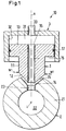
- Fig. 1 shows in a sectional view of a first embodiment of a connection arrangement according to the invention, which is provided overall with the reference numeral 10, and which includes an embodiment of the high-pressure connection, which is generally designated by the reference numeral 1.
- the connection assembly 10 comprises a pressure accumulator 2 for a fluid and an only indicated device 3, which is operated by means of the pressurized fluid.
- the fluid may be any gaseous or liquid medium used in pressurized working processes, such as hydraulic oil or servo oil for hydraulically actuating or controlling pistons, valves or the like, fuel for injection into the cylinder of an internal combustion engine, or water must be transported under pressure.
- hydraulic oil or servo oil for hydraulically actuating or controlling pistons, valves or the like, fuel for injection into the cylinder of an internal combustion engine, or water must be transported under pressure.
- the device 3 may be any device operated by means of a pressurized fluid, for example a control valve, a hydraulically operated piston, a pump, or a pressure line carrying the fluid.
- the pressure accumulator 2 for example, tubular, in particular cylindrical, be designed as a pressure tube with a cylinder axis L, as well as the pressure accumulators, which are used today in common rail systems.
- the pressure accumulator 2 comprises a wall 21, the inside of which has a storage space 22 for the pressurized fluid.
- the pressure accumulator 2 comprises at least one connecting bore 23, which extends from the storage space 22 radially outwardly through the wall 21, and which opens into a seat surface 24.
- the seat 24 is conical.
- a plurality of connecting bores 23 are provided in the tubular pressure accumulator 2 of a common rail system, which are shown in relation to the cylinder axis L according to ( Fig. 1 ) are arranged one behind the other. Since it is sufficient for the understanding, the following explanations are limited to only one connection hole 23.
- the high-pressure connection 1 comprises a body 11 which extends in the direction of a longitudinal axis A from a first end surface 12 to a second end surface 13.
- the first end surface 12 is configured for sealing engagement with the seat surface 24.
- the first end surface 12 is designed as a conical surface or as a frustoconical surface.
- the associated cone angle of the first end face 12 can be the same size as the cone surface belonging to the seat surface 24 or-depending on the material-also somewhat smaller.
- Fig. 1 It is understood that in the operating state, the high-pressure connection 1 is pressed with its first end face 12 in the seat surface 24, so as to create a high-pressure-tight connection between the pressure accumulator 2 and the high-pressure connection 1 , If the cone angle associated with the first seat surface 12 is undersized compared to the seat surface 24, the first end surface 12 deforms in the operating state by the prevailing pressure and adapts to the seat surface 24.
- the first end face 12 has an inlet opening 14, through which the fluid from the storage space 22 of the pressure accumulator 2 can flow into the high-pressure connection 1. From the inlet opening 14 extends a centrally disposed passage bore 15 in the direction of the longitudinal axis A up to an outlet opening 16, which is provided in the second end face 13.
- the second end face 13 is configured in this embodiment as a circular surface or as an annular surface.
- the second end face 13 is designed such that it can be received by the device 3.
- the device 3 has a cavity or bore 31 which is bounded by a wall 32, and which the second end surface 13 receives.
- the body 11 of the high-pressure connection 1 has a groove which extends over the entire circumference, and in which a sealing element 17, for example an O-ring, inserted between the wall 32 and the body 11 seals.
- the first and second end surfaces 12 and 13 each have an effective area. This means the effective area over which the pressure which acts on the respective end face 12, 13 can produce a force in the direction of the longitudinal axis-that is to say upward or downward as shown.
- the active surface is thus the vertical projection of the respective end face 12, 13 on the plane which is perpendicular to the longitudinal axis A.
- the effective area is the same size as the cross-sectional area at the in Fig. 1 indicated by the arrow W1 point.
- the effective area is the same size as the second end face 13.
- the effective area of the second end face 13 is greater than the effective area of the first end face 12.
- the pressurized fluid flows from the storage space 22 of the pressure accumulator 2 through the connection bore 23 and the passage bore 15 in the part of the bore 31 of the device 3, which is located above the second end face 13 as shown. From there, the fluid may, for example, flow through a channel 33 in order to be available in the device 3.
- the second end surface 13 is acted upon by the fluid at substantially the same pressure, which also prevails in the storage space 22. Since the second end face 13 has an effective area which is larger than the effective area of the first end face 12, in any case a result in the direction of the longitudinal axis - according to the drawing down - directed force, which presses the first end surface 12 sealingly against the seat surface 24. Thus, a sealing function caused by the pressure of the fluid can be achieved.
- the fuel injection, the gas exchange, possibly the water injection and auxiliary system with common rail systems are operated.
- the respective fluid for.
- a hydraulic medium such as servo oil for actuating the exhaust valves or a working medium for controlling the injection under high pressure in a pressure accumulator promoted, which is also referred to as an accumulator.
- the accumulators are each designed as a tube-like, closed at both ends components that extend approximately at the level of the cylinder heads along the engine.
- the pressure can be up to 2000 bar, for example.
- the pressure of the hydraulic medium eg servo oil
- the pressure of the hydraulic medium can be up to 300 bar.
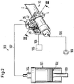
- Fig. 2 shows in a partially schematic representation of those essential for the understanding of the invention parts of an embodiment of a large diesel engine according to the invention, which is provided overall with the reference numeral 100.
- this embodiment is a slow-current, longitudinally-flushed 2-stroke large diesel engine 100 with a cross-head drive.
- the large diesel engine 100 comprises a second exemplary embodiment of a connection arrangement 10 according to the invention, which in FIG Fig. 3 can be seen in a sectional view. The section is taken along the section line III-III in Fig. 2 ,
- the large diesel engine 100 usually includes a plurality of cylinders 101, of which in Fig. 1 only one can be seen.
- a piston 102 is arranged to be movable back and forth.
- the piston 102 is connected via a piston rod 103 with a crosshead, not shown, which in turn is connected via a push rod with a crankshaft (not shown).
- an exhaust valve 104 is provided, which is hydraulically actuated in a conventional manner. This actuation takes place via a common rail system which comprises the second exemplary embodiment of the connection arrangement 10 according to the invention.
- the common rail system for the control of the exhaust valve 104 includes the pressure accumulator 2, which is designed as a pressure tube for the hydraulic medium.
- the device 3 is here a valve control unit 3, which via the high-pressure connection 1 (see Fig. 3 ) is connected to the connection bore 23 of the pressure accumulator 2.
- the second end face 13 of the high-pressure connection 1 is analogous to that in FIG Fig. 1 shown arranged in the bore 31 of the valve control unit 3. In this case, the high-pressure connection 1 is received without thread from the valve control unit.
- the valve control unit 3 comprises an electrically piloted main control valve 35 and an electromagnetic pilot valve 36, which is controlled by a control unit 105 via a signal line 106. As soon as the pilot control valve 36 opens the main control valve 35, the hydraulic medium can flow from the pressure accumulator 2 through a pressure line 107 to the outlet valve 104 in order to open it.
- a pump 108 is provided which conveys the hydraulic medium from a reservoir, not shown, via a line 109 into the pressure accumulator 2.
- valve control unit 3 If only one valve control unit 3 is shown, it is understood, however, that for each cylinder 101 a respective valve control unit 3 is provided which is connected in each case via a high-pressure connection 1 to a separate connection bore 23 of the pressure accumulator 2.
- the accumulator 2 is connected via a holder 4 with the valve control unit 3 (see also Fig. 3 ).
- the holder 4 surrounds the pressure accumulator 2 in the manner of a pipe clamp.
- a flange 18 is provided on the body 11, which is provided with two unthreaded holes for receiving first screws 41.
- the first screws 41 which engage in threaded holes in the holder 4, the high-pressure connection 1 is attached to the holder 4, namely here screwed.
- the first end surface 12 is pressed into the seat surface 24, so that already a seal between the high-pressure connection 1 and the pressure accumulator 2 takes place. As a result, at least one primary seal is achieved.
- the second end face 13 is inserted into the bore 31, wherein the designed as an O-ring sealing member 17 between the wall 32 of the bore 31 and the body 11 of the high-pressure connection 1 seals. Then, the valve control unit 3 is mounted by means of second screws 42 to the Hält ceremonies 4 and tightened.
- the hydraulic medium also acts on the second end face 13 of the high-pressure connection, which is located in the bore 31 of the valve control unit 3 (see also FIG Fig. 1 ) is arranged, with pressure. Since the effective area of the second end face 13 is greater than the effective area of the first end face 12, the high-pressure connection 1 is pressed with its first end face 12 sealingly into the seat surface 24 of the pressure accumulator 2.
- connection assembly 10 comprising the pressure accumulator 2, the high-pressure connection 1, the valve control unit 3 and the holder 4 is preferably carried out only via the valve control unit 3. Since - as already mentioned - a plurality of valve control units 3 are provided supported the connection assembly 10 over several locations.
- the valve control unit 3 is fixedly attached to the large diesel engine 100 or to a support 5 provided therefor, as shown in FIG Fig. 3 is indicated.
- the pressure accumulator 2 is with respect to its normal position of use, which the representation in Fig. 2 and Fig. 3 corresponds, mounted on the bracket 4 laterally adjacent to the valve control unit 3.
- the designed as a pressure tube pressure accumulator 2 has no direct support on the engine or on the motor housing, but is supported only on the valve control units 3.
- a further advantage is that due to the holders 4, the pressure accumulator 2 no longer has to have a plane surface on its outside, which on the one hand increases the mechanical stability and on the other hand simplifies production.
- the wall 21 of the accumulator 2 is free of holes and free of tapped holes, because both the first mounting screws 41 and the second mounting screws 42 engage in the holder 4, but not in the wall 21 of the pressure accumulator 2. This increases the mechanical stability the accumulator 2 quite considerably, which can lead to the pressure accumulator 2 can be made despite the same operating pressure with a thinner wall 21.
Description
Die Erfindung betrifft eine Verbindungsanordnung mit einem Druckspeicher gemäss dem Oberbegriff des unabhängigen Anspruchs. Die Erfindung betrifft ferner einen Grossdieselmotor mit einer solchen mit einer solchen Verbindungsanordnung.The invention relates to a connection arrangement with a pressure accumulator according to the preamble of the independent claim. The invention further relates to a large diesel engine with such a with such a connection arrangement.
In Vorrichtungen, in denen Fluide, insbesondere Flüssigkeiten, unter hohem Druck geführt werden müssen, benötigt man zwischen den einzelnen Komponenten Verbindungen, die dem hohen Druck standhalten und zudem dicht sein müssen. Als Beispiel seien hier Grossdieselmotoren genannt, die als Zweitakt- oder als Viertakt-Maschinen ausgestaltet sein können, und die häufig als Antriebsaggregate für Schiffe oder auch im stationären Betrieb, z.B. zum Antrieb grosser Generatoren zur Erzeugung elektrischer Energie eingesetzt werden.In devices in which fluids, in particular liquids, must be conducted under high pressure, it is necessary between the individual components compounds that withstand the high pressure and also must be tight. As an example may be mentioned here large diesel engines, which may be configured as two-stroke or four-stroke engines, and often as drive units for ships or in stationary operation, e.g. be used to drive large generators for generating electrical energy.
In modernen Grossdieselmotoren sind es insbesondere zwei Medien, die unter sehr hohen Drücken transportiert werden, zum einen der Brennstoff, der mit einem Druck von bis zu mehr als 1000 bar zu den Einspritzdüsen transportiert wird, und zum anderen ein Hydraulikmedium, das üblicherweise als Servoöl bezeichnet wird. Das Hydraulikmedium dient beispielsweise der hydraulischen Betätigung der Auslassventile. Diese Medien werden von Pumpen in Druckspeicher gefördert, die als Druckrohre ausgestaltet sind und sich oft entlang des gesamten Zylinderbereichs erstrecken. Aus diesen Druckspeichern, die auch als Akkumulatoren bezeichnet werden, gelangt das Medium zu den Einspritzorganen oder zu den Steuer- bzw. Betätigungsvorrichtungen für die hydraulischen Komponenten.
Die Verbindung zwischen den Druckspeichern und den Vorrichtungen, die das Medium benötigen, basieren häufig auf Verschraubungen, bei denen die Vorrichtung direkt auf die Wandung des Druckspeichers aufgeschraubt wird, oder auf Hochdruckleitungen, die über ein Gewinde dichtend in eine entsprechende Auslassbohrung des Druckspeichers eingepresst werden. Auch sind geschweisste oder gelötete Verbindungen bekannt.
Die Aufgabe der Erfindung ist es, eine andere, konstruktiv einfache und zuverlässige Hochdruckverbindung vorzuschlagen, mit der ein unter Druck stehendes Fluid von einem Druckspeicher zu einer Vorrichtung geführt werden kann. Ferner soll eine derartige Verbindungsanordnung vorgeschlagen werden. Insbesondere soll die Hochdruckverbindung für den Einsatz in Grossdieselmotoren geeignet sein.
Die diese Aufgaben lösenden Gegenstände der Erfindung sind durch die Merkmale des unabhängigen Anspruchs gekennzeichnet.In modern large diesel engines, there are two media in particular, which are transported under very high pressures, on the one hand, the fuel, which is transported to the injection nozzles with a pressure of up to more than 1000 bar, and on the other a hydraulic medium, commonly referred to as servo oil becomes. The hydraulic medium is used for example hydraulic actuation of the exhaust valves. These media are conveyed by pumps in accumulators, which are designed as pressure pipes and often extend along the entire cylinder area. From these pressure accumulators, which are also referred to as accumulators, the medium passes to the injectors or to the control or actuating devices for the hydraulic components.
The connection between the pressure accumulators and the devices that require the medium are often based on screwed connections, in which the device is screwed directly onto the wall of the pressure accumulator, or on high pressure lines, which are pressed by a thread sealingly into a corresponding outlet bore of the pressure accumulator. Also, welded or soldered connections are known.
The object of the invention is to propose another, structurally simple and reliable high-pressure connection with which a pressurized fluid can be conducted from a pressure accumulator to a device. Furthermore, such a connection arrangement should be proposed. In particular, the high-pressure connection should be suitable for use in large diesel engines.
The objects of the invention solving these objects are characterized by the features of the independent claim.
Mit der Wirkfläche ist dabei die senkrechte Projektion der jeweiligen Endfläche auf diejenige Ebene gemeint, die senkrecht zur Längsachse liegt, also die Fläche, welche für die von dem Fluid auf die Endfläche ausgeübte Kraft massgeblich ist. Da die Wirkfläche für die zweite Endfläche grösser ist als für die erste Endfläche, der von dem Fluid ausgeübte Druck aber im wesentlichen auf beiden Endflächen gleich ist, wirkt im Betriebszustand durch das Fluid auf die zweite Endfläche eine grössere Kraft als auf die erste Endfläche, sodass die Hochdruckverbindung mit ihrer ersten Endfläche dichtend in die Sitzfläche gepresst wird. Somit lässt sich eine hochdruckdichte Verbindung realisieren, die durch das unter Druck stehende Fluid abgedichtet wird. Prinzipiell sind für diese Dichtfunktion weder Schrauben noch Verschweissungen notwendig. Die erste Endfläche ist wie erwähnt als Kegelfläche oder Kegelstumpffläche ausgestaltet. Mit dieser Geometrie der ersten Endfläche lässt sich eine besonders gute Dichtwirkung an der Verbindung mit dem Druckspeicher erzielen.
Vorteilhafterweise ist die zweite Endfläche als Kreisfläche ausgestaltet. Dies ist zum einen konstruktiv einfach und maximiert die Wirkfläche der zweiten Endfläche bei vorgegebenem Durchmesser der zweiten Endfläche.In this case, the active surface means the vertical projection of the respective end face onto that plane which is perpendicular to the longitudinal axis, that is to say the surface which is decisive for the force exerted by the fluid on the end face. Since the effective area for the second end surface is greater than for the first end surface, but the pressure exerted by the fluid is substantially equal on both end surfaces, a larger force acts on the second end surface by the fluid than on the first end surface by the fluid the high-pressure connection is pressed with its first end surface sealingly into the seat. Thus, a high-pressure-tight connection can be realized, which is sealed by the pressurized fluid. In principle, neither screws nor welds are necessary for this sealing function. As mentioned, the first end surface is designed as a conical surface or truncated cone surface. With this geometry of the first end surface, a particularly good sealing effect can be achieved at the connection to the pressure accumulator.
Advantageously, the second end surface is designed as a circular surface. This is on the one hand structurally simple and maximizes the effective area of the second end face for a given diameter of the second end face.
Bei dieser Verbindungsanordnung erfolgt die Abdichtung zwischen der Hochdruckverbindung und dem Druckspeicher hauptsächlich durch den Druck des Fluids auf die zweite Endfläche. Da deren Wirkfläche grösser ist als die Wirkfläche der ersten Endfläche, resultiert eine Kraft, welche die erste Endfläche dichtend gegen die Sitzfläche des Druckspeichers presst.In this connection arrangement, the seal between the high-pressure connection and the pressure accumulator is effected mainly by the pressure of the fluid on the second end surface. Since their effective area is greater than the effective area of the first end surface, results in a force which presses the first end surface sealingly against the seat surface of the pressure accumulator.
Ein für die Praxis wichtiger Anwendungsfall ist es, dass der Druckspeicher als Druckrohr ausgestaltet ist.An important application in practice is that the pressure accumulator is designed as a pressure tube.
Konstruktiv ist es vorgesehen, dass die Vorrichtung bezüglich der normalen Gebrauchslage seitlich am Druckspeicher befestigt ist. Damit lässt es sich vermeiden, dass Druckschläge, die im Betriebszustand der Vorrichtung auftreten, beispielsweise durch das Öffnen, Schliessen oder Schalten von Ventilen, zu einer Krafteinleitung in das Druckrohr führen.It is structurally provided that the device is fastened laterally to the pressure accumulator with respect to the normal position of use. This makes it possible to avoid pressure surges that are in the operating state of the device occur, for example, by opening, closing or switching valves, lead to a force in the pressure tube.
Eine weitere vorteilhafte Massnahme ist es, wenn eine Halterung vorgesehen ist, welche den Druckspeicher umgreift, wobei die Hochdruckverbindung an der Halterung befestigt ist. Somit lässt es sich vermeiden, die Hochdruckverbindung unmittelbar in der Wandung des Druckspeichers festzuschrauben.A further advantageous measure is when a holder is provided which surrounds the pressure accumulator, wherein the high-pressure connection is attached to the holder. Thus, it is possible to avoid screwing the high pressure connection directly in the wall of the pressure accumulator.
Vorzugsweise ist die zweite Endfläche der Hochdruckverbindung in einer Bohrung der Vorrichtung angeordnet. Durch diese Massnahme ist es möglich, dass das Fluid besonders gut einen Druck auf die zweite Endfläche ausüben kann.Preferably, the second end surface of the high pressure connection is disposed in a bore of the device. By this measure, it is possible that the fluid can exert a particularly good pressure on the second end surface.
Vorteilhafterweise ist die Hochdruckverbindung ohne Gewinde von der Vorrichtung aufgenommen, sodass sich die Kraft optimal von der zweiten auf die erste Endfläche übertragen kann.Advantageously, the high-pressure connection is received without thread from the device, so that the force can be optimally transmitted from the second to the first end face.
Bei einer bevorzugten Anwendung ist der Druckspeicher ein Druckrohr für Hydraulikmedium oder Brennstoff in einem Grossdieselmotor.
Durch die Erfindung wird ferner ein Grossdieselmotor vorgeschlagen mit einer erfindungsgemässen Verbindungsanordnung.
Bei einem erfindungsgemässen Grossdieselmotor ist der Druckspeicher ein Druckrohr für Hydraulikmedium oder Brennstoff, wobei das Druckrohr über die Vorrichtung abgestützt ist und wobei das Druckrohr bezüglich der normalen Gebrauchslage seitlich an der Vorrichtung befestigt ist. Hierdurch wird nämlich erreicht, dass Druckschläge in der Vorrichtung in deren Abstützung abgeleitet werden und nicht zu einer wesentlichen Krafteinleitung in das Druckrohr führen.In a preferred application, the pressure accumulator is a pressure tube for hydraulic medium or fuel in a large diesel engine.
The invention further proposes a large diesel engine with a connection arrangement according to the invention.
In a large diesel engine according to the invention, the pressure accumulator is a pressure tube for hydraulic medium or fuel, wherein the pressure tube is supported by the device and wherein the pressure tube is fixed laterally relative to the normal position of use of the device. In this way, it is achieved that pressure surges in the device are derived in their support and do not lead to a significant force into the pressure tube.
Eine für die Praxis besonders relevante Anwendung ist es, wenn die Vorrichtung eine Ventilsteuereinheit für die hydraulische Ansteuerung eines Auslassventils ist.A particularly relevant application in practice is when the device is a valve control unit for the hydraulic control of an exhaust valve.
Weitere vorteilhafte Massnahmen und bevorzugte Ausgestaltungen der Erfindung ergeben sich aus den abhängigen Ansprüchen.Further advantageous measures and preferred embodiments of the invention will become apparent from the dependent claims.
Im Folgenden wird die Erfindung anhand von Ausführungsbeispielen und anhand der Zeichnung näher erläutert. In der schematischen, nicht massstäblichen Zeichnung zeigen teilweise im Schnitt:
- Fig. 1:
- ein erstes Ausführungsbeispiel einer erfindungsgemässen Verbindungsanordnung mit einem Ausführungsbeispiel der Hochdruckverbindung,
- Fig. 2:
- ein Ausführungsbeispiel eines erfindungsgemässen Grossdieselmotors mit einem zweiten Ausführungsbeispiel einer erfindungsgemässen Verbindungsanordnung, und
- Fig. 3:
- eine Schnittdarstellung des zweiten Ausführungsbeispiel entlang der Schnittlinie III-III in
Fig. 2 .
- Fig. 1:
- A first embodiment of an inventive connection arrangement with an embodiment of the high-pressure connection,
- Fig. 2:
- an embodiment of a large diesel engine according to the invention with a second embodiment of a connection arrangement according to the invention, and
- 3:
- a sectional view of the second embodiment along the section line III-III in
Fig. 2 ,
Das Fluid kann jedes gasförmige oder flüssige Medium sein, das in Arbeitsprozessen unter Druck eingesetzt wird, beispielsweise ein Hydrauliköl oder ein Servoöl zur hydraulischen Betätigung oder Ansteuerung von Kolben, Ventilen oder ähnlichem, Brennstoff für die Einspritzung in den Zylinder einer Brennkraftmaschine, oder Wasser, das unter Druck befördert werden muss.The fluid may be any gaseous or liquid medium used in pressurized working processes, such as hydraulic oil or servo oil for hydraulically actuating or controlling pistons, valves or the like, fuel for injection into the cylinder of an internal combustion engine, or water must be transported under pressure.
Die Vorrichtung 3 kann jede beliebige Vorrichtung sein, die mittels eines unter Druck stehenden Fluids betrieben wird, beispielsweise ein Steuerventil, ein hydraulisch betriebener Kolben, eine Pumpe, oder eine Druckleitung, welche das Fluid führt.The
Der Druckspeicher 2 kann beispielsweise rohrförmig, insbesondere zylindrisch, als Druckrohr mit einer Zylinderachse L ausgestaltet sein, so wie die Druckspeicher, die heute in Common Rail Systemen eingesetzt werden. Der Druckspeicher 2 umfasst eine Wandung 21, deren Innenseite einen Speicherraum 22 für das unter Druck stehende Fluid aufweist. Der Druckspeicher 2 umfasst mindestens eine Anschlussbohrung 23, die sich vom Speicherraum 22 radial nach aussen durch die Wandung 21 erstreckt, und die in eine Sitzfläche 24 mündet. Die Sitzfläche 24 ist konisch ausgestaltet.The
Typischerweise sind bei dem rohrförmigen Druckspeicher 2 eines Common Rail Systems mehrere Anschlussbohrungen 23 vorgesehen, die bezüglich der Zylinderachse L darstellungsgemäss (
Die Hochdruckverbindung 1 umfasst einen Körper 11, der sich in Richtung einer Längsachse A von einer ersten Endfläche 12 zu einer zweiten Endfläche 13 erstreckt. Die erste Endfläche 12 ist zum dichtenden Zusammenwirken mit der Sitzfläche 24 ausgestaltet. Im vorliegenden Ausführungsbeispiel ist die erste Endfläche 12 als Kegelfläche bzw. als Kegelstumpffläche ausgestaltet. Dabei kann der zugehörige Konuswinkel der ersten Endfläche 12 gleich gross sein wie der zu der Sitzfläche 24 gehörende Konuswinkel oder - je nach Material - auch etwas kleiner.The high-
Die erste Endfläche 12 weist eine Einlassöffnung 14 auf, durch welche das Fluid aus dem Speicherraum 22 des Druckspeichers 2 in die Hochdruckverbindung 1 strömen kann. Von der Einlassöffnung 14 erstreckt sich eine zentral angeordnete Durchlassbohrung 15 in Richtung der Längsachse A bis zu einer Auslassöffnung 16, welche in der zweiten Endfläche 13 vorgesehen ist. Die zweite Endfläche 13 ist bei diesem Ausführungsbeispiel als Kreisfläche bzw. als Ringfläche ausgestaltet.The
Die zweite Endfläche 13 ist so ausgestaltet, dass sie von der Vorrichtung 3 aufgenommen werden kann. Die Vorrichtung 3 weist eine Kavität oder eine Bohrung 31 auf, welche von einer Wand 32 begrenzt wird, und welche die zweite Endfläche 13 aufnimmt. Darstellungsgermäss unterhalb der zweiten Endfläche 13 weist der Körper 11 der Hochdruckverbindung 1 eine Nut auf, die sich über den gesamten Umfang erstreckt, und in welche ein Dichtelement 17, beispielsweise ein O-Ring, eingelegt ist, das zwischen der Wand 32 und dem Körper 11 abdichtet.The
Die erste und die zweite Endfläche 12 bzw. 13 haben jeweils eine Wirkfläche. Damit ist die effektive Fläche gemeint, über die der Druck, welcher auf die jeweilige Endfläche 12, 13 wirkt, eine Kraft in Richtung der Längsachse - also darstellungsgemäss nach oben oder nach unten - erzeugen kann. Die Wirkfläche ist somit die senkrechte Projektion der jeweiligen Endfläche 12, 13 auf die Ebene, die senkrecht zur Längsachse A liegt. Für die erste Endfläche 12 ist die Wirkfläche gleich gross wie die Querschnittsfläche an der in
Erfindungsgemäss ist die Wirkfläche der zweiten Endfläche 13 grösser als die Wirkfläche der ersten Endfläche 12.According to the invention, the effective area of the
Im Betriebszustand strömt das unter Druck stehende Fluid aus dem Speicherraum 22 des Druckspeichers 2 durch die Anschlussbohrung 23 und die Durchlassbohrung 15 in den Teil der Bohrung 31 der Vorrichtung 3, der sich darstellungsgemäss oberhalb der zweiten Endfläche 13 befindet. Von dort kann das Fluid beispielsweise durch einen Kanal 33 strömen, um in der Vorrichtung 3 zur Verfügung zu stehen.In the operating state, the pressurized fluid flows from the
Die zweite Endfläche 13 ist durch das Fluid im Wesentlichen mit dem gleichen Druck beaufschlagt, der auch im Speicherraum 22 herrscht. Da die zweite Endfläche 13 eine Wirkfläche hat, die grösser ist als die Wirkfläche der ersten Endfläche 12, resultiert auf jeden Fall eine in Richtung der Längsachse - darstellungsgemäss nach unten - gerichtete Kraft, welche die erste Endfläche 12 dichtend gegen die Sitzfläche 24 presst. Somit lässt sich eine Dichtfunktion erzielen, die durch den Druck des Fluids verursacht wird.The
Für diese Dichtung ist im Prinzip keine Verschraubung und auch keine andere Befestigung, z. B. durch Schweissen oder Löten vonnöten. Es versteht sich aber, dass zusätzlich Schrauben oder andere Befestigungs- oder Führungsmittel vorgesehen sein können, beispielsweise um die Hochdruckverbindung 1 in der Richtung der Längsachse A zu führen oder um Verkippungen der Hochdruckverbindung 1 zu vermeiden oder um eine primäre Abdichtung zu erzielen. Dies wird beispielhaft anhand des zweiten Ausführungsbeispiels erläutert.For this seal is in principle no screwing and no other attachment, z. B. by welding or soldering needed. However, it is understood that additional screws or other fastening or guiding means may be provided, for example, to guide the high-
Bei dem zweiten Ausführungsbeispiel wird auf den für die Praxis wichtigen Anwendungsfall eines Grossdieselmotors Bezug genommen. In modernen Grossdieselmotoren werden die Brennstoffeinspritzung, der Gaswechsel, gegebenenfalls die Wassereinspritzung und Hilfssystem mit Common Rail Systemen betrieben. Dabei wird mittels Pumpen das jeweilige Fluid, z. B. der Brennstoff für die Einspritzung, ein Hydraulikmedium wie Servoöl zur Betätigung der Auslassventile oder ein Arbeitsmedium zur Steuerung der Einspritzung unter Hochdruck in einen Druckspeicher gefördert, der auch als Akkumulator bezeichnet wird. Mit dem unter Druck stehenden Fluid aus dem jeweiligen Akkumulator werden dann sämtliche Zylinder der Brennkraftmaschine versorgt bzw. die Ventile und die Brennstoffeinspritzvorrichtungen angesteuert. Üblicherweise sind die Druckspeicher jeweils als rohrähnliche, an beiden Enden geschlossene Bauteile ausgestaltet, die sich etwa auf Höhe der Zylinderköpfe entlang des Motors erstrecken.In the second embodiment, reference is made to the important application in practice of a large diesel engine. In modern large diesel engines, the fuel injection, the gas exchange, possibly the water injection and auxiliary system with common rail systems are operated. In this case, by means of pumps the respective fluid, for. As the fuel for injection, a hydraulic medium such as servo oil for actuating the exhaust valves or a working medium for controlling the injection under high pressure in a pressure accumulator promoted, which is also referred to as an accumulator. With the pressurized fluid from the respective accumulator all cylinders of the internal combustion engine are then supplied or actuated the valves and the fuel injectors. Usually, the accumulators are each designed as a tube-like, closed at both ends components that extend approximately at the level of the cylinder heads along the engine.
Die höchsten Drücke treten typischerweise im Common Rail System für die Brennstoffeinspritzung auf. Im zugehörigen Druckspeicher kann der Druck beispielsweise bis 2000 bar betragen. Im Druckspeicher des Common Rail Systems für die Betätigung der Auslassventile kann der Druck des Hydraulikmediums (z. B. Servoöl) bis 300 bar betragen.The highest pressures typically occur in the common rail fuel injection system. In the associated pressure accumulator, the pressure can be up to 2000 bar, for example. In the pressure accumulator of the common rail system for the actuation of the exhaust valves, the pressure of the hydraulic medium (eg servo oil) can be up to 300 bar.
Von der Funktion her gleiche oder gleichwertige Teile sind in
Der Grossdieselmotor 100 umfasst üblicherweise mehrere Zylinder 101, von denen in
An jedem Zylinder ist ein Auslassventil 104 vorgesehen, das in an sich bekannter Weise hydraulisch betätigt wird. Diese Betätigung erfolgt über ein Common Rail System, welches das zweite Ausführungsbeispiel der erfindungsgemässen Verbindungsanordnung 10 umfasst. Das Common Rail System für die Ansteuerung des Auslassventils 104 umfasst den Druckspeicher 2, der als Druckrohr für das Hydraulikmedium ausgestaltet ist.On each cylinder, an
Die Vorrichtung 3 ist hier eine Ventilsteuereinheit 3, welche über die Hochdruckverbindung 1 (siehe
Ferner ist eine Pumpe 108 vorgesehen, welche das Hydraulikmedium aus einem nicht dargestellten Vorratsbehälter über eine Leitung 109 in den Druckspeicher 2 fördert.Furthermore, a
In
Der Druckspeicher 2 ist über eine Halterung 4 mit der Ventilsteuereinheit 3 verbunden (siehe auch
Zum Verbinden der Hochdruckverbindung 1 mit der Ventilsteuereinheit 3 wird die zweite Endfläche 13 in die Bohrung 31 eingeführt, wobei das als O-Ring ausgestaltete Dichtelement 17 zwischen der Wand 32 der Bohrung 31 und dem Körper 11 der Hochdruckverbindung 1 abdichtet. Dann wird die Ventilsteuereinheit 3 mittels zweiter Schrauben 42 an der Hälterung 4 montiert und festgeschraubt.For connecting the high-
Im Betriebszustand beaufschlagt das Hydraulikmedium auch die zweite Endfläche 13 der Hochdruckverbindung, die in der Bohrung 31 der Ventilsteuereinheit 3 (siehe auch
Die gesamte Abstützung der Verbindungsanordnung 10 umfassend den Druckspeicher 2, die Hochdruckverbindung 1, die Ventilsteuereinheit 3 und die Halterung 4 erfolgt vorzugsweise nur über die Ventilsteuereinheit 3. Da - wie bereits erwähnt - mehrere Ventilsteuereinheiten 3 vorgesehen sind, ist die Verbindungsanordnung 10 über mehrere Stellen abgestützt. Die Ventilsteuereinheit 3 ist fest am Grossdieselmotor 100 bzw. an einer dafür vorgesehenen Auflage 5 befestigt, wie dies in
Es ist Stand der Technik, den Druckspeicher fest am Motor zu montieren, beispielsweise auf einer Auflage, und zwar so, dass die Anschlussbohrungen bezüglich der normalen Gebrauchslage vertikal nach oben weisen. Die Vorrichtungen 3 bzw. die Ventilsteuereinheiten 3 befinden sich dann oben auf dem Druckspeicher. Dazu muss der Druckspeicher an seiner Oberseite eine plane Fläche für die Montage der Ventilsteuereinheiten aufweisen, die mit Schrauben auf dieser planen Fläche festmontiert werden. Diese Schrauben greifen dann in die Wandung des Druckspeichers ein, das heisst die Wandung des Druckspeichers muss mit Gewindebohrungen versehen werden. Bei dieser vertikalen Anordnung gehen die dynamischen Kräfte, die beispielsweise beim Schalten der Ventilsteuereinheiten auftreten, durch den Druckspeicher in die Auflage. Die gesamte Anordnung wird über den Druckspeicher abgestützt.It is state of the art to mount the pressure accumulator firmly on the engine, for example on a support, in such a way that the connection bores point vertically upwards relative to the normal position of use. The
Gegenüber diesem Stand der Technik hat die Anordnung des Druckspeichers 2 seitlich an der Vorrichtung 3 bzw. der Ventilsteuereinheit 3 einige Vorteile:
- So werden die dynamischen Kräfte, die beispielsweise beim Schalten der Ventilsteuereinheiten 3 auftreten, im wesentlichen nicht in
den Druckspeicher 2 eingeleitet, sondern werdenvon der Ventilsteuereinheit 3 direkt auf dieAuflage 5 übertragen. Dies reduziert die mechanische Belastung desDruckspeichers 2 deutlich.
- Thus, the dynamic forces that occur, for example, when switching the
valve control units 3, essentially not introduced into thepressure accumulator 2, but are transmitted from thevalve control unit 3 directly to thesupport 5. This significantly reduces the mechanical load on thepressure accumulator 2.
Ein weiterer Vorteil ist es, dass durch die Halterungen 4 bedingt, der Druckspeicher 2 keine plane Fläche mehr an seiner Aussenseite aufweisen muss, was einerseits die mechanische Stabilität erhöht und andererseits die Herstellung vereinfacht.A further advantage is that due to the
Ferner ist die Wandung 21 des Druckspeichers 2 frei von Bohrungen und frei von Gewindebohrungen, denn sowohl die ersten Befestigungsschrauben 41 als auch die zweiten Befestigungsschrauben 42 greifen in die Halterung 4, nicht aber in die Wandung 21 des Druckspeichers 2. Hierdurch erhöht sich die mechanische Stabilität des Druckspeichers 2 ganz erheblich, was dazu führen kann, dass der Druckspeicher 2 trotz gleichem Betriebsdrucks mit einer dünneren Wandung 21 gefertigt werden kann.Furthermore, the
Claims (9)
- A connection arrangement having a pressure reservoir (2) for a pressurized fluid, an apparatus (3) which is operated by means of the fluid and a high pressure connection (1) through which the fluid can arrive at the apparatus (3) from the pressure reservoir (2), wherein the pressure reservoir (2) is made as a pressure pipe and has at least one connection bore (23) which opens into a seating surface (24), wherein the apparatus (3) is laterally fastened to the pressure reservoir (2) made as a pressure pipe with regards to the normal position of operation., so that the support of the pressure reservoir (2) is effected only via the apparatus (3), wherein the high pressure connection includes a body (11) which extends in the direction of a longitudinal axis (A) from a first end face (12) to a second end face (13), wherein the first end face (12) is adapted to sealingly cooperate with the seating surface (24) and has an inlet opening (14) and wherein the second end face (13) has an outlet opening (16) which is connected to the inlet opening (14) via a passage bore (15), wherein the high pressure connection (1) contacts the seating surface (24) with its first end face (12) and is received with its second end face (13) by a cavity of the apparatus (3), such that the fluid can flow from the pressure reservoir (2) via the passage bore (15) of the high pressure connection (1) into the apparatus (3), wherein the second end face (13) has an active surface for the fluid which is larger than the active surface of the first end face (12), wherein the first end face (12) is made as a conical surface or a frustoconical surface extending in the direction away from the second end face (13) with tapering decreasing diameter.
- A connection arrangement in accordance with any one of the preceding claims, wherein the second end face (13) is made as a circular surface.
- A connection arrangement in accordance with any one of claims 1-2, in which a mounting (4) is provided which surrounds the pressure reservoir (2), wherein the high pressure connection (1) is attached to the mounting (4).
- A connection arrangement in accordance with any one of claims -1-3, in which the second end face (13) of the high pressure connection (1) is arranged in a bore (31) of the apparatus (3).
- A connection arrangement in accordance with any one of the preceding claims,, in which the high pressure connection (1) is received by the apparatus (3) without a thread.
- A connection arrangement in accordance with any one of the preceding claims,, in which the pressure reservoir (2) is a pressure pipe for a hydraulic medium or fuel in a large diesel engine (100).
- A large diesel engine having a connection arrangement in accordance with any one of the preceding claims,.
- A large diesel engine in accordance with claim 7, in which the pressure reservoir (2) is a pressure pipe for a hydraulic medium or a fuel, wherein the pressure pipe is supported via the apparatus (3) and wherein the pressure pipe is laterally fastened to the apparatus (3) with regards to the normal position of operation.
- A large diesel engine in accordance with claim 7 or 8, wherein the apparatus (3) is a valve control unit for the hydraulic actuation of an outlet valve (104).
Priority Applications (1)
| Application Number | Priority Date | Filing Date | Title |
|---|---|---|---|
| EP10168213.6A EP2295786B1 (en) | 2009-08-04 | 2010-07-02 | Connection arrangement |
Applications Claiming Priority (2)
| Application Number | Priority Date | Filing Date | Title |
|---|---|---|---|
| EP09167159 | 2009-08-04 | ||
| EP10168213.6A EP2295786B1 (en) | 2009-08-04 | 2010-07-02 | Connection arrangement |
Publications (2)
| Publication Number | Publication Date |
|---|---|
| EP2295786A1 EP2295786A1 (en) | 2011-03-16 |
| EP2295786B1 true EP2295786B1 (en) | 2016-04-13 |
Family
ID=41508721
Family Applications (1)
| Application Number | Title | Priority Date | Filing Date |
|---|---|---|---|
| EP10168213.6A Active EP2295786B1 (en) | 2009-08-04 | 2010-07-02 | Connection arrangement |
Country Status (4)
| Country | Link |
|---|---|
| EP (1) | EP2295786B1 (en) |
| JP (1) | JP5715354B2 (en) |
| KR (1) | KR101711652B1 (en) |
| BR (1) | BRPI1002285A2 (en) |
Families Citing this family (2)
| Publication number | Priority date | Publication date | Assignee | Title |
|---|---|---|---|---|
| EP2511517B1 (en) * | 2011-04-15 | 2015-04-01 | Wärtsilä Schweiz AG | A high pressure fluid rail |
| RU2553917C1 (en) * | 2014-04-28 | 2015-06-20 | Федеральное государственное унитарное предприятие "Центральный ордена Трудового Красного Знамени научно-исследовательский автомобильный и автомоторный институт "НАМИ" | Device for liquid fuel supply into diesel engine nozzles |
Family Cites Families (12)
| Publication number | Priority date | Publication date | Assignee | Title |
|---|---|---|---|---|
| US2712458A (en) * | 1950-06-05 | 1955-07-05 | Lipson Leonard | Pipe couplings |
| DE1295936B (en) * | 1964-12-10 | 1969-05-22 | Le Nii Khim Maschinos | Pipe seal |
| JP2527268Y2 (en) * | 1990-05-11 | 1997-02-26 | 三菱重工業株式会社 | Valve train for internal combustion engine |
| JPH09133280A (en) * | 1995-11-08 | 1997-05-20 | Kanzaki Kokyukoki Mfg Co Ltd | Fluid connecting device |
| JP3882964B2 (en) * | 1996-11-30 | 2007-02-21 | 臼井国際産業株式会社 | Connection structure of branch connection in common rail |
| DE19936535A1 (en) * | 1999-08-03 | 2001-02-15 | Bosch Gmbh Robert | High pressure fuel accumulator |
| JP4212752B2 (en) * | 2000-02-18 | 2009-01-21 | 株式会社オティックス | Common rail |
| JP2003148283A (en) * | 2001-11-06 | 2003-05-21 | Denso Corp | Valve unit and fuel injection device using the same |
| DE10161438B4 (en) * | 2001-12-14 | 2004-07-15 | Man B&W Diesel A/S | reciprocating engine |
| JP4075838B2 (en) * | 2003-06-27 | 2008-04-16 | 株式会社デンソー | Piping joint device |
| DE602005002368T2 (en) * | 2005-07-08 | 2008-05-29 | C.R.F. Società Consortile per Azioni, Orbassano | Arrangement for connecting a fuel reservoir for fuel under pressure and at least one injector, for an internal combustion engine |
| JP2007056816A (en) * | 2005-08-26 | 2007-03-08 | Usui Kokusai Sangyo Kaisha Ltd | Connection structure for branched connection pipe |
-
2010
- 2010-07-02 EP EP10168213.6A patent/EP2295786B1/en active Active
- 2010-07-29 BR BRPI1002285-6A patent/BRPI1002285A2/en not_active IP Right Cessation
- 2010-08-02 KR KR1020100074540A patent/KR101711652B1/en active IP Right Grant
- 2010-08-02 JP JP2010173879A patent/JP5715354B2/en active Active
Also Published As
| Publication number | Publication date |
|---|---|
| KR101711652B1 (en) | 2017-03-02 |
| CN101988451A (en) | 2011-03-23 |
| KR20110014111A (en) | 2011-02-10 |
| JP2011033190A (en) | 2011-02-17 |
| JP5715354B2 (en) | 2015-05-07 |
| BRPI1002285A2 (en) | 2012-06-05 |
| EP2295786A1 (en) | 2011-03-16 |
Similar Documents
| Publication | Publication Date | Title |
|---|---|---|
| EP1485609B1 (en) | Device for injecting fuel to stationary internal combustion engines | |
| AT412228B (en) | FUEL RAIL | |
| DE19535368C2 (en) | Fuel injection device for internal combustion engines | |
| EP1636483B1 (en) | Valve for controlling liquids | |
| EP2295786B1 (en) | Connection arrangement | |
| EP1918570B1 (en) | Fuel injector with accumulator volume segment | |
| DE4225350A1 (en) | Fuel injection pump for internal combustion engines | |
| DE4405432C1 (en) | High pressure accumulator as fuel distribution pipe, especially for an internal combustion engine with common-rail system | |
| EP1685323B1 (en) | Device for damping pressure surges | |
| EP1262657A2 (en) | Fuel injection system for internal combustion engines, in particular for diesel engines | |
| DE19952513A1 (en) | Fuel injection system for internal combustion engines with constant leakage oil pressure in the injector | |
| DE102019207390B4 (en) | Cylinder head for an internal combustion engine with a fuel rail and an injector, method of assembly and use therefor | |
| EP1407134A1 (en) | High-pressure fuel device | |
| EP2836696B1 (en) | Injector of a modular common-rail fuel injection system with throughflow limiter | |
| EP1117923A1 (en) | High-pressure fuel accumulator | |
| DE10309311B4 (en) | Fuel high pressure storage | |
| WO2014026846A1 (en) | Thread connection for connecting components conducting high pressure medium | |
| DE102018201279B4 (en) | High-pressure connection for a high-pressure fuel pump of a fuel injection system and high-pressure fuel pump | |
| DE19938999C2 (en) | Injector with a lubricated transmission element | |
| EP1319128B1 (en) | Fuel injection valve for internal combustion engines | |
| DE10047805B4 (en) | valve assembly | |
| DE10020506B4 (en) | Device for supplying fuel to injection valves of an internal combustion engine | |
| DE102012110240A1 (en) | Fuel injection injector for internal combustion engines | |
| DE10050599B4 (en) | Injection valve with a pump piston | |
| EP1426607A1 (en) | Pressure accumulator for a Common Rail system |
Legal Events
| Date | Code | Title | Description |
|---|---|---|---|
| PUAI | Public reference made under article 153(3) epc to a published international application that has entered the european phase |
Free format text: ORIGINAL CODE: 0009012 |
|
| AK | Designated contracting states |
Kind code of ref document: A1 Designated state(s): AL AT BE BG CH CY CZ DE DK EE ES FI FR GB GR HR HU IE IS IT LI LT LU LV MC MK MT NL NO PL PT RO SE SI SK SM TR |
|
| AX | Request for extension of the european patent |
Extension state: BA ME RS |
|
| 17P | Request for examination filed |
Effective date: 20110916 |
|
| 17Q | First examination report despatched |
Effective date: 20120206 |
|
| GRAP | Despatch of communication of intention to grant a patent |
Free format text: ORIGINAL CODE: EPIDOSNIGR1 |
|
| INTG | Intention to grant announced |
Effective date: 20151104 |
|
| GRAS | Grant fee paid |
Free format text: ORIGINAL CODE: EPIDOSNIGR3 |
|
| GRAA | (expected) grant |
Free format text: ORIGINAL CODE: 0009210 |
|
| INTG | Intention to grant announced |
Effective date: 20160217 |
|
| AK | Designated contracting states |
Kind code of ref document: B1 Designated state(s): AL AT BE BG CH CY CZ DE DK EE ES FI FR GB GR HR HU IE IS IT LI LT LU LV MC MK MT NL NO PL PT RO SE SI SK SM TR |
|
| REG | Reference to a national code |
Ref country code: GB Ref legal event code: FG4D Free format text: NOT ENGLISH |
|
| REG | Reference to a national code |
Ref country code: AT Ref legal event code: REF Ref document number: 790435 Country of ref document: AT Kind code of ref document: T Effective date: 20160415 Ref country code: CH Ref legal event code: EP |
|
| REG | Reference to a national code |
Ref country code: IE Ref legal event code: FG4D Free format text: LANGUAGE OF EP DOCUMENT: GERMAN |
|
| REG | Reference to a national code |
Ref country code: DE Ref legal event code: R096 Ref document number: 502010011416 Country of ref document: DE |
|
| REG | Reference to a national code |
Ref country code: LT Ref legal event code: MG4D |
|
| REG | Reference to a national code |
Ref country code: NL Ref legal event code: MP Effective date: 20160413 |
|
| PG25 | Lapsed in a contracting state [announced via postgrant information from national office to epo] |
Ref country code: NL Free format text: LAPSE BECAUSE OF FAILURE TO SUBMIT A TRANSLATION OF THE DESCRIPTION OR TO PAY THE FEE WITHIN THE PRESCRIBED TIME-LIMIT Effective date: 20160413 Ref country code: LT Free format text: LAPSE BECAUSE OF FAILURE TO SUBMIT A TRANSLATION OF THE DESCRIPTION OR TO PAY THE FEE WITHIN THE PRESCRIBED TIME-LIMIT Effective date: 20160413 Ref country code: PL Free format text: LAPSE BECAUSE OF FAILURE TO SUBMIT A TRANSLATION OF THE DESCRIPTION OR TO PAY THE FEE WITHIN THE PRESCRIBED TIME-LIMIT Effective date: 20160413 Ref country code: NO Free format text: LAPSE BECAUSE OF FAILURE TO SUBMIT A TRANSLATION OF THE DESCRIPTION OR TO PAY THE FEE WITHIN THE PRESCRIBED TIME-LIMIT Effective date: 20160713 Ref country code: FI Free format text: LAPSE BECAUSE OF FAILURE TO SUBMIT A TRANSLATION OF THE DESCRIPTION OR TO PAY THE FEE WITHIN THE PRESCRIBED TIME-LIMIT Effective date: 20160413 |
|
| PG25 | Lapsed in a contracting state [announced via postgrant information from national office to epo] |
Ref country code: GR Free format text: LAPSE BECAUSE OF FAILURE TO SUBMIT A TRANSLATION OF THE DESCRIPTION OR TO PAY THE FEE WITHIN THE PRESCRIBED TIME-LIMIT Effective date: 20160714 Ref country code: LV Free format text: LAPSE BECAUSE OF FAILURE TO SUBMIT A TRANSLATION OF THE DESCRIPTION OR TO PAY THE FEE WITHIN THE PRESCRIBED TIME-LIMIT Effective date: 20160413 Ref country code: HR Free format text: LAPSE BECAUSE OF FAILURE TO SUBMIT A TRANSLATION OF THE DESCRIPTION OR TO PAY THE FEE WITHIN THE PRESCRIBED TIME-LIMIT Effective date: 20160413 Ref country code: SE Free format text: LAPSE BECAUSE OF FAILURE TO SUBMIT A TRANSLATION OF THE DESCRIPTION OR TO PAY THE FEE WITHIN THE PRESCRIBED TIME-LIMIT Effective date: 20160413 Ref country code: PT Free format text: LAPSE BECAUSE OF FAILURE TO SUBMIT A TRANSLATION OF THE DESCRIPTION OR TO PAY THE FEE WITHIN THE PRESCRIBED TIME-LIMIT Effective date: 20160816 Ref country code: ES Free format text: LAPSE BECAUSE OF FAILURE TO SUBMIT A TRANSLATION OF THE DESCRIPTION OR TO PAY THE FEE WITHIN THE PRESCRIBED TIME-LIMIT Effective date: 20160413 |
|
| PG25 | Lapsed in a contracting state [announced via postgrant information from national office to epo] |
Ref country code: IT Free format text: LAPSE BECAUSE OF FAILURE TO SUBMIT A TRANSLATION OF THE DESCRIPTION OR TO PAY THE FEE WITHIN THE PRESCRIBED TIME-LIMIT Effective date: 20160413 Ref country code: BE Free format text: LAPSE BECAUSE OF NON-PAYMENT OF DUE FEES Effective date: 20160731 |
|
| REG | Reference to a national code |
Ref country code: DE Ref legal event code: R097 Ref document number: 502010011416 Country of ref document: DE |
|
| PG25 | Lapsed in a contracting state [announced via postgrant information from national office to epo] |
Ref country code: RO Free format text: LAPSE BECAUSE OF FAILURE TO SUBMIT A TRANSLATION OF THE DESCRIPTION OR TO PAY THE FEE WITHIN THE PRESCRIBED TIME-LIMIT Effective date: 20160413 Ref country code: DK Free format text: LAPSE BECAUSE OF FAILURE TO SUBMIT A TRANSLATION OF THE DESCRIPTION OR TO PAY THE FEE WITHIN THE PRESCRIBED TIME-LIMIT Effective date: 20160413 Ref country code: SK Free format text: LAPSE BECAUSE OF FAILURE TO SUBMIT A TRANSLATION OF THE DESCRIPTION OR TO PAY THE FEE WITHIN THE PRESCRIBED TIME-LIMIT Effective date: 20160413 Ref country code: CZ Free format text: LAPSE BECAUSE OF FAILURE TO SUBMIT A TRANSLATION OF THE DESCRIPTION OR TO PAY THE FEE WITHIN THE PRESCRIBED TIME-LIMIT Effective date: 20160413 Ref country code: EE Free format text: LAPSE BECAUSE OF FAILURE TO SUBMIT A TRANSLATION OF THE DESCRIPTION OR TO PAY THE FEE WITHIN THE PRESCRIBED TIME-LIMIT Effective date: 20160413 |
|
| PLBE | No opposition filed within time limit |
Free format text: ORIGINAL CODE: 0009261 |
|
| STAA | Information on the status of an ep patent application or granted ep patent |
Free format text: STATUS: NO OPPOSITION FILED WITHIN TIME LIMIT |
|
| PG25 | Lapsed in a contracting state [announced via postgrant information from national office to epo] |
Ref country code: SM Free format text: LAPSE BECAUSE OF FAILURE TO SUBMIT A TRANSLATION OF THE DESCRIPTION OR TO PAY THE FEE WITHIN THE PRESCRIBED TIME-LIMIT Effective date: 20160413 |
|
| REG | Reference to a national code |
Ref country code: CH Ref legal event code: PL |
|
| 26N | No opposition filed |
Effective date: 20170116 |
|
| GBPC | Gb: european patent ceased through non-payment of renewal fee |
Effective date: 20160713 |
|
| PG25 | Lapsed in a contracting state [announced via postgrant information from national office to epo] |
Ref country code: MC Free format text: LAPSE BECAUSE OF FAILURE TO SUBMIT A TRANSLATION OF THE DESCRIPTION OR TO PAY THE FEE WITHIN THE PRESCRIBED TIME-LIMIT Effective date: 20160413 |
|
| PG25 | Lapsed in a contracting state [announced via postgrant information from national office to epo] |
Ref country code: FR Free format text: LAPSE BECAUSE OF NON-PAYMENT OF DUE FEES Effective date: 20160801 Ref country code: LI Free format text: LAPSE BECAUSE OF NON-PAYMENT OF DUE FEES Effective date: 20160731 Ref country code: CH Free format text: LAPSE BECAUSE OF NON-PAYMENT OF DUE FEES Effective date: 20160731 |
|
| REG | Reference to a national code |
Ref country code: FR Ref legal event code: ST Effective date: 20170331 |
|
| REG | Reference to a national code |
Ref country code: IE Ref legal event code: MM4A |
|
| PG25 | Lapsed in a contracting state [announced via postgrant information from national office to epo] |
Ref country code: GB Free format text: LAPSE BECAUSE OF NON-PAYMENT OF DUE FEES Effective date: 20160713 Ref country code: SI Free format text: LAPSE BECAUSE OF FAILURE TO SUBMIT A TRANSLATION OF THE DESCRIPTION OR TO PAY THE FEE WITHIN THE PRESCRIBED TIME-LIMIT Effective date: 20160413 |
|
| PG25 | Lapsed in a contracting state [announced via postgrant information from national office to epo] |
Ref country code: IE Free format text: LAPSE BECAUSE OF NON-PAYMENT OF DUE FEES Effective date: 20160702 |
|
| PG25 | Lapsed in a contracting state [announced via postgrant information from national office to epo] |
Ref country code: LU Free format text: LAPSE BECAUSE OF NON-PAYMENT OF DUE FEES Effective date: 20160702 |
|
| REG | Reference to a national code |
Ref country code: AT Ref legal event code: MM01 Ref document number: 790435 Country of ref document: AT Kind code of ref document: T Effective date: 20160702 |
|
| PG25 | Lapsed in a contracting state [announced via postgrant information from national office to epo] |
Ref country code: AT Free format text: LAPSE BECAUSE OF NON-PAYMENT OF DUE FEES Effective date: 20160702 |
|
| PG25 | Lapsed in a contracting state [announced via postgrant information from national office to epo] |
Ref country code: HU Free format text: LAPSE BECAUSE OF FAILURE TO SUBMIT A TRANSLATION OF THE DESCRIPTION OR TO PAY THE FEE WITHIN THE PRESCRIBED TIME-LIMIT; INVALID AB INITIO Effective date: 20100702 Ref country code: CY Free format text: LAPSE BECAUSE OF FAILURE TO SUBMIT A TRANSLATION OF THE DESCRIPTION OR TO PAY THE FEE WITHIN THE PRESCRIBED TIME-LIMIT Effective date: 20160413 |
|
| PG25 | Lapsed in a contracting state [announced via postgrant information from national office to epo] |
Ref country code: TR Free format text: LAPSE BECAUSE OF FAILURE TO SUBMIT A TRANSLATION OF THE DESCRIPTION OR TO PAY THE FEE WITHIN THE PRESCRIBED TIME-LIMIT Effective date: 20160413 Ref country code: MK Free format text: LAPSE BECAUSE OF FAILURE TO SUBMIT A TRANSLATION OF THE DESCRIPTION OR TO PAY THE FEE WITHIN THE PRESCRIBED TIME-LIMIT Effective date: 20160413 Ref country code: MT Free format text: LAPSE BECAUSE OF FAILURE TO SUBMIT A TRANSLATION OF THE DESCRIPTION OR TO PAY THE FEE WITHIN THE PRESCRIBED TIME-LIMIT Effective date: 20160413 Ref country code: IS Free format text: LAPSE BECAUSE OF FAILURE TO SUBMIT A TRANSLATION OF THE DESCRIPTION OR TO PAY THE FEE WITHIN THE PRESCRIBED TIME-LIMIT Effective date: 20160413 |
|
| PG25 | Lapsed in a contracting state [announced via postgrant information from national office to epo] |
Ref country code: BG Free format text: LAPSE BECAUSE OF FAILURE TO SUBMIT A TRANSLATION OF THE DESCRIPTION OR TO PAY THE FEE WITHIN THE PRESCRIBED TIME-LIMIT Effective date: 20160413 |
|
| PG25 | Lapsed in a contracting state [announced via postgrant information from national office to epo] |
Ref country code: AL Free format text: LAPSE BECAUSE OF FAILURE TO SUBMIT A TRANSLATION OF THE DESCRIPTION OR TO PAY THE FEE WITHIN THE PRESCRIBED TIME-LIMIT Effective date: 20160413 |
|
| PGFP | Annual fee paid to national office [announced via postgrant information from national office to epo] |
Ref country code: DE Payment date: 20230719 Year of fee payment: 14 |