JP4212752B2 - Common rail - Google Patents
Common rail Download PDFInfo
- Publication number
- JP4212752B2 JP4212752B2 JP2000041036A JP2000041036A JP4212752B2 JP 4212752 B2 JP4212752 B2 JP 4212752B2 JP 2000041036 A JP2000041036 A JP 2000041036A JP 2000041036 A JP2000041036 A JP 2000041036A JP 4212752 B2 JP4212752 B2 JP 4212752B2
- Authority
- JP
- Japan
- Prior art keywords
- hole
- primary
- branch
- rail
- branch connection
- Prior art date
- Legal status (The legal status is an assumption and is not a legal conclusion. Google has not performed a legal analysis and makes no representation as to the accuracy of the status listed.)
- Expired - Fee Related
Links
Images


Classifications
-
- F—MECHANICAL ENGINEERING; LIGHTING; HEATING; WEAPONS; BLASTING
- F02—COMBUSTION ENGINES; HOT-GAS OR COMBUSTION-PRODUCT ENGINE PLANTS
- F02M—SUPPLYING COMBUSTION ENGINES IN GENERAL WITH COMBUSTIBLE MIXTURES OR CONSTITUENTS THEREOF
- F02M55/00—Fuel-injection apparatus characterised by their fuel conduits or their venting means; Arrangements of conduits between fuel tank and pump F02M37/00
- F02M55/02—Conduits between injection pumps and injectors, e.g. conduits between pump and common-rail or conduits between common-rail and injectors
- F02M55/025—Common rails
Landscapes
- Engineering & Computer Science (AREA)
- Chemical & Material Sciences (AREA)
- Combustion & Propulsion (AREA)
- Mechanical Engineering (AREA)
- General Engineering & Computer Science (AREA)
- Fuel-Injection Apparatus (AREA)
Description
【0001】
【発明の属する技術分野】
本発明は、エンジンのコモンレール式燃料噴射装置におけるコモンレールに関するものである。
【0002】
【従来の技術】
図9及び図10は従来のコモンレール式燃料噴射装置におけるコモンレール50を示し、主管51に主管長方向に延びるレール穴52が形成されている。主管51の一端は圧力センサ7の接続部53となっており、主管51の他端は圧力制御弁6の接続部54となっている。主管51の管側面の1箇所にはレール穴52に交差開口する分岐穴55が形成され、主管51の同箇所から分岐した分岐接続部56には分岐穴55から延びる連通穴57が形成され、該分岐接続部56が燃料吸入パイプ3の接続部となっている。また、主管51の管側面の他方側の複数箇所にはレール穴52に交差開口する複数の分岐穴58が形成され、主管51の同箇所から分岐した分岐接続部59には各分岐穴58から延びる連通穴60が形成され、該分岐接続部59が燃料排出パイプ5の接続部となっている。
【0003】
【発明が解決しようとする課題】
従来のコモンレール50は、エンジンの気筒数に応じた数の分岐接続部59が、主管長方向に所定間隔をおいて直列に形成されているため、エンジンの多気筒化(例えば4気筒から6気筒〜12気筒へ)に伴って分岐接続部59の数が多くなると、コモンレール50が主管長方向に大型化し、エンジン搭載スペース上、困難となる。
【0004】
また、本出願人は先に、コモンレールの高圧化対応として、主管のレール穴の細径化を提案しているが(特願平11−196987:本出願時において未公開)、同案においてはレール穴の細径化により内容積調整部(貯留室)の設置が必要となるため、やはりコモンレール50が主管長方向に大型化する。
【0005】
本発明の第一の目的は、上記課題を解決し、コモンレールを主管長方向にコンパクト化し、エンジン搭載スペースを削減してエンジンの多気筒化に対応することにある。また、第二の目的は、分岐穴の穴周囲部に集中する応力を低減し、超高圧化のニーズに対応することにある。
【0006】
【課題を解決するための手段】
上記目的を達成するために、本発明に係るコモンレールは、主管にレール穴と該レール穴に開口する一次分岐穴とを形成し、主管から分岐した一次分岐接続部に一次分岐穴から延びる一次連通穴と該一次連通穴に開口する二次分岐穴とを形成し、一次分岐接続部から分岐した二次分岐接続部に二次分岐穴から延びる二次連通穴を形成し、レール穴を内径が相対的に小さい主通路部と内径が相対的に大きい内容積調整部とから構成し、一次分岐穴を主通路部に開口して内容積調整部には開口しないように配置したことを特徴とする。
本発明に係る別のコモンレールは、主管にレール穴と該レール穴に開口する一次分岐穴とを形成し、主管から分岐した一次分岐接続部に一次分岐穴から延びる一次連通穴と該一次連通穴に開口する二次分岐穴とを形成し、一次分岐接続部から分岐した二次分岐接続部に二次分岐穴から延びる二次連通穴を形成し、一次分岐接続部及び二次分岐接続部の接続相手としては、次の(1)〜(3)のいずれかの態様であることを特徴とする。
(1)一次分岐接続部を燃料吸入パイプ又は燃料排出パイプの接続部とし、二次分岐接続部を燃料吸入パイプ又は燃料排出パイプの接続部とした態様。
(2)一次分岐接続部を圧力制御弁又は圧力センサの接続部とし、二次分岐接続部を燃料吸入パイプ又は燃料排出パイプの接続部とした態様。
(3)一次分岐接続部を燃料吸入パイプ又は燃料排出パイプの接続部とし、二次分岐接続部を圧力制御弁又は圧力センサの接続部とした態様。
また、レール穴を内径が相対的に小さい主通路部と内径が相対的に大きい内容積調整部とから構成し、一次分岐穴を主通路部に開口して内容積調整部には開口しないように配置することもできる。
【0007】
ここで、主管と一次分岐接続部と二次分岐接続部とを一体形成することが好ましい。一体形成の方法は、特に限定されないが、鍛造又は鋳造を例示することができる。
【0008】
また、レール穴の内径よりも一次連通穴の内径を小さくすることが好ましい。一次連通穴の内径を小さくすると、燃料圧力により負荷される一次連通穴の内周面の応力が小さくなり、二次分岐穴の穴周囲部に集中する応力が低減されるからである。
【0009】
また、主通路部と内容積調整部との数及び配置の仕方は、特に限定されず、一つの主通路部と一つの内容積調整部とを単純に並べた配置や、一つの主通路部を二つの内容積調整部で挟むようにした配置を例示することができる。
【0011】
【発明の実施の形態】
[第一実施形態]
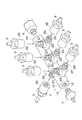
図1〜図4は、本発明を6気筒ディーゼルエンジンのコモンレールに具体化した第一実施形態を示している。図4はコモンレール式燃料噴射装置全体の概略を示し、コモンレール1の管側部には、燃料ポンプ2から延びる燃料吸入パイプ3とインジェクタ4へ延びる燃料排出パイプ5とが接続され、コモンレール1の端部には、圧力制御弁(リリーフバルブ)6と圧力センサ7とが接続される。燃料ポンプ2とインジェクタ4は電子制御装置8により制御される。
【0012】
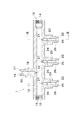
図1〜図3に示すように、コモンレール1の主管10には、主管長方向に延びるレール穴11が形成されている。主管10の一端はレール穴11に続く雌ねじ12が形成されて圧力センサ7の接続部13となっており、主管10の他端はレール穴11に続く雌ねじ14が形成されて圧力制御弁6の接続部15となっている。
【0013】
主管10の管側面の一方側の1箇所には、レール穴11の途中箇所に交差開口する分岐穴16が形成されている。主管10の同箇所から分岐した分岐接続部17には、分岐穴16から延びる連通穴18が形成されている。分岐接続部17は、端面に連通穴18から続くテーパー状のシール面19が開口するとともに、端部外周に雄ねじ20が形成されることにより、燃料吸入パイプ3の接続部となっている。すなわち、燃料吸入パイプ3の端部に取り付けられたカラー(図示略:但し、後述するカラー31と同様)の凸球面状のシール面をシール面19に密着させ、該カラーに係合する接続部材35の雌ねじ36を雄ねじ20に螺合させて接続する。
【0014】
主管10の管側面の他方側の3箇所には、レール穴11の途中箇所に交差開口する3つの一次分岐穴21が形成されている。主管10の同箇所から分岐した(すなわち主管長方向に所定間隔をおいて直列に形成された)3つの一次分岐接続部22には、各一次分岐穴21から延びる一次連通穴23と該一次連通穴23の途中箇所に開口する二次分岐穴24とが形成されている。一次分岐接続部22は、端面に一次連通穴23から続くテーパー状のシール面25が開口するとともに、端部外周に雄ねじ26が形成されることにより、燃料排出パイプ5の接続部となっている。すなわち、燃料排出パイプ5の端部に取り付けられたカラー31の凸球面状のシール面32をシール面25に密着させ、該カラー31に係合する接続部材35の雌ねじ36を雄ねじ26に螺合させて接続する。
【0015】
各一次分岐接続部22の途中箇所から分岐した二次分岐接続部27には各二次分岐穴24から延びる二次連通穴28が形成されている。二次分岐接続部27は、端面に二次連通穴28から続くテーパー状のシール面29が開口するとともに、端部外周に雄ねじ30が形成されることにより、燃料排出パイプ5の接続部となっている。すなわち、燃料排出パイプ5の端部に取り付けられたカラー31の凸球面状のシール面32をシール面29に密着させ、該カラー31に係合する接続部材35の雌ねじ36を雄ねじ30に螺合させて接続する。
【0016】
なお、主管10と分岐接続部17と一次分岐接続部22と二次分岐接続部27とは、鍛造により一体形成されている。
【0017】
以上のように構成されたコモンレール1によれば、一次分岐接続部22にさらに二次分岐接続部27を設けたことにより、主管長方向に直列に形成される一次分岐接続部22の数を気筒数よりも減らすことができるので、コモンレール1を主管長方向にコンパクト化し、エンジン搭載スペースを削減してエンジン多気筒化に対応することができる。
【0018】
また、一次分岐穴21と二次分岐穴24とは互いに影響し合わないように離れている。さらに、レール穴11の内径よりも一次連通穴23の内径が小さくなっているため、燃料圧力による一次連通穴23の内周面の応力が小さくなり、二次分岐穴24の穴周囲部に集中する応力が低減される。これにより、超高圧化のニーズに対応することができる。
【0019】
[第二実施形態]
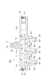
図5〜図7に示す第二実施形態のコモンレール40は、第一実施形態のコモンレール1に対して、一次分岐接続部22及び二次分岐接続部27(内部の各穴21,23,24,28も含む)の数を一つ増やし、その増やした一次分岐接続部22を(一次連通穴23に続く雌ねじ41を形成することにより)圧力制御弁6の接続部とするとともに、二次分岐接続部27を燃料吸入パイプ3の接続部としたものである。この変更に伴い、主管10の端の雌ねじ14はメクラ雄ねじ42により塞がれ、第一実施形態では形成されていた分岐接続部17(内部の各穴16,18も含む)は形成されていない。なお、該一次分岐接続部22には圧力センサ7を接続するようにしてもよい。
【0020】
本実施形態によっても、第一実施形態とほぼ同様の効果が得られる。すなわち、第一実施形態に対して一次分岐接続部22の数は1つ増えるが、圧力制御弁6が主管長方向に突出しなくなるため、コモンレール40を主管長方向にコンパクト化できる。
【0021】
[第三実施形態]
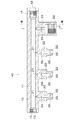
図8に示す第三実施形態のコモンレール45は、第一実施形態のコモンレールに対して、レール穴11を内径が相対的に小さい主通路部11aと内径が相対的に大きい内容積調整部(貯留室)11bとから構成し、一次分岐穴21を主通路部11aに開口して内容積調整部11bには開口しないように左側に偏在配置したものである。レール穴11の内容積は第一実施形態のレール穴11の内容積と略同一であるが、主通路部11aの内径は第一実施形態のレール穴11より細径化されており、内容積調整部11bの内径は第一実施形態のレール穴11より太径化されている。
【0022】
本実施形態によれば、主通路部11aの細径化により内容積調整部11bの設置が必要となるが、第一実施形態と同じく一次分岐接続部22の数を減らすことができるので、結果としてコモンレール45を主管長方向にコンパクト化できる。さらに、主通路部11aの細径化により、加圧燃料による主通路部11aの内周面の応力が小さくなるので、一次分岐穴21の穴周囲部に集中する応力が低減される。よって、超高圧化のニーズに対応することができる。
【0023】
なお、本発明は前記実施形態に限定されるものではなく、例えば以下のように、発明の趣旨から逸脱しない範囲で適宜変更して具体化することもできる。
(1)一次分岐接続部22及び二次分岐接続部27の数を、気筒数に応じて適宜変更すること。
(2)1つの一次分岐接続部22について二以上の二次分岐接続部27(内部の各穴も含む)を形成すること。
【0024】
【発明の効果】
以上詳述した通り、本発明のコモンレールによれば、コモンレールを主管長方向にコンパクト化でき、エンジン搭載スペースを削減してエンジンの多気筒化に対応することができる。さらに、レール穴を主通路部と内容積調整部とから構成し、一次分岐穴を主通路部に開口して内容積調整部には開口しないように配置したもの、又は、レール穴の内径よりも一次連通穴の内径を小さくしたものによれば、分岐穴の穴周囲部に集中する応力を低減でき、超高圧化のニーズに対応することができる。
【図面の簡単な説明】
【図1】本発明の第一実施形態に係るコモンレールの斜視図である。
【図2】同コモンレールの断面図である。
【図3】図2のIII−III線断面図である。
【図4】コモンレール式燃料噴射装置の概略図である。
【図5】本発明の第二実施形態に係るコモンレールの斜視図である。
【図6】同コモンレールの断面図である。
【図7】図6のVII−VII線断面図である。
【図8】本発明の第三実施形態に係るコモンレールの断面図である。
【図9】従来例に係るコモンレールの断面図である。
【図10】同コモンレールの断面図である。
【符号の説明】
1 コモンレール
3 燃料吸入パイプ
5 燃料排出パイプ
6 圧力制御弁
7 圧力センサ
10 主管
11 レール穴
11a 主通路部
11b 内容積調整部
21 一次分岐穴
22 一次分岐接続部
23 一次連通穴
24 二次分岐穴
27 二次分岐接続部
28 二次連通穴
31 カラー
35 接続部材
40 コモンレール
45 コモンレール[0001]
BACKGROUND OF THE INVENTION
The present invention relates to a common rail in an engine common rail fuel injection device.
[0002]
[Prior art]
9 and 10 show a
[0003]
[Problems to be solved by the invention]
In the conventional
[0004]
In addition, the present applicant has previously proposed a reduction in the diameter of the rail hole of the main pipe as a countermeasure for the high pressure of the common rail (Japanese Patent Application No. 11-196987: not disclosed at the time of this application). Since the inner volume adjusting part (reservoir chamber) needs to be installed by reducing the diameter of the rail hole, the
[0005]
A first object of the present invention is to solve the above problems, to make the common rail compact in the main pipe length direction, to reduce the engine mounting space, and to cope with the increase in the number of cylinders in the engine. The second object is to reduce the stress concentrated on the peripheral part of the branch hole and meet the need for ultra high pressure.
[0006]
[Means for Solving the Problems]
To achieve the above object, a common rail according to the present invention forms a primary component岐穴to open the rail hole and the rail holes in the main pipe, primary extending from the primary branch hole in the primary branch connection portion which is branched from the main pipe A communication hole and a secondary branch hole that opens to the primary communication hole are formed, a secondary communication hole that extends from the secondary branch hole is formed in the secondary branch connection part branched from the primary branch connection part, and the rail hole has an inner diameter. Is composed of a relatively small main passage portion and an internal volume adjustment portion having a relatively large inner diameter, and is arranged so that the primary branch hole is opened in the main passage portion and not in the internal volume adjustment portion. And
Another common rail according to the present invention forms a rail hole in the main pipe and a primary branch hole opened in the rail hole, and the primary communication hole and the primary communication hole extend from the primary branch hole to the primary branch connection portion branched from the main pipe. A secondary branch hole extending from the secondary branch hole is formed in the secondary branch connection portion branched from the primary branch connection portion, and the primary branch connection portion and the secondary branch connection portion are formed. The connection partner is any one of the following (1) to (3).
(1) A mode in which the primary branch connection portion is a connection portion of the fuel intake pipe or the fuel discharge pipe, and the secondary branch connection portion is a connection portion of the fuel intake pipe or the fuel discharge pipe.
(2) A mode in which the primary branch connection portion is a pressure control valve or pressure sensor connection portion and the secondary branch connection portion is a fuel intake pipe or fuel discharge pipe connection.
(3) A mode in which the primary branch connection portion is a fuel intake pipe or fuel discharge pipe connection portion, and the secondary branch connection portion is a pressure control valve or pressure sensor connection portion.
Further, the rail hole is composed of a main passage portion having a relatively small inner diameter and an inner volume adjusting portion having a relatively large inner diameter, and the primary branch hole is opened in the main passage portion so as not to be opened in the inner volume adjusting portion. It can also be arranged.
[0007]
Here, it is preferable to integrally form the main pipe, the primary branch connection portion, and the secondary branch connection portion. Although the method of integral formation is not specifically limited, Forging or casting can be illustrated.
[0008]
In addition, it is preferable to make the inner diameter of the primary communication hole smaller than the inner diameter of the rail hole. This is because if the inner diameter of the primary communication hole is reduced, the stress on the inner peripheral surface of the primary communication hole that is loaded by the fuel pressure is reduced, and the stress concentrated around the hole of the secondary branch hole is reduced.
[0009]
In addition , the number and arrangement of the main passage portions and the internal volume adjustment portions are not particularly limited, and an arrangement in which one main passage portion and one internal volume adjustment portion are simply arranged or one main passage portion is provided. An arrangement in which the two are sandwiched between two inner volume adjusting portions can be exemplified.
[0011]
DETAILED DESCRIPTION OF THE INVENTION
[First embodiment]
1 to 4 show a first embodiment in which the present invention is embodied in a common rail of a 6-cylinder diesel engine. FIG. 4 shows an outline of the entire common rail type fuel injection apparatus. A
[0012]
As shown in FIGS. 1 to 3, a
[0013]
A
[0014]
Three
[0015]
A
[0016]
In addition, the
[0017]
According to the
[0018]
Further, the
[0019]
[Second Embodiment]
The
[0020]
Also according to the present embodiment, substantially the same effect as the first embodiment can be obtained. That is, although the number of primary
[0021]
[Third embodiment]
The
[0022]
According to the present embodiment, it is necessary to install the internal
[0023]
In addition, this invention is not limited to the said embodiment, For example, it can also be suitably changed and embodied as follows, for example in the range which does not deviate from the meaning of invention.
(1) The number of primary
(2) Forming two or more secondary branch connection portions 27 (including internal holes) for one primary
[0024]
【The invention's effect】
As described above in detail, according to the common rail of the present invention, the common rail can be made compact in the main pipe length direction, and the engine mounting space can be reduced to cope with the increase in the number of cylinders in the engine. Furthermore, the rail hole is composed of a main passage portion and an internal volume adjusting portion, and the primary branch hole is opened in the main passage portion but not in the internal volume adjusting portion, or from the inner diameter of the rail hole However, if the inner diameter of the primary communication hole is made smaller , the stress concentrated around the branch hole can be reduced, and the need for an ultra-high pressure can be met .
[Brief description of the drawings]
FIG. 1 is a perspective view of a common rail according to a first embodiment of the present invention.
FIG. 2 is a cross-sectional view of the common rail.
3 is a cross-sectional view taken along line III-III in FIG.
FIG. 4 is a schematic view of a common rail fuel injection device.
FIG. 5 is a perspective view of a common rail according to a second embodiment of the present invention.
FIG. 6 is a sectional view of the common rail.
7 is a cross-sectional view taken along line VII-VII in FIG.
FIG. 8 is a cross-sectional view of a common rail according to a third embodiment of the present invention.
FIG. 9 is a cross-sectional view of a common rail according to a conventional example.
FIG. 10 is a sectional view of the common rail.
[Explanation of symbols]
DESCRIPTION OF
Claims (7)
Priority Applications (1)
| Application Number | Priority Date | Filing Date | Title |
|---|---|---|---|
| JP2000041036A JP4212752B2 (en) | 2000-02-18 | 2000-02-18 | Common rail |
Applications Claiming Priority (1)
| Application Number | Priority Date | Filing Date | Title |
|---|---|---|---|
| JP2000041036A JP4212752B2 (en) | 2000-02-18 | 2000-02-18 | Common rail |
Publications (3)
| Publication Number | Publication Date |
|---|---|
| JP2001227430A JP2001227430A (en) | 2001-08-24 |
| JP2001227430A5 JP2001227430A5 (en) | 2006-09-21 |
| JP4212752B2 true JP4212752B2 (en) | 2009-01-21 |
Family
ID=18564325
Family Applications (1)
| Application Number | Title | Priority Date | Filing Date |
|---|---|---|---|
| JP2000041036A Expired - Fee Related JP4212752B2 (en) | 2000-02-18 | 2000-02-18 | Common rail |
Country Status (1)
| Country | Link |
|---|---|
| JP (1) | JP4212752B2 (en) |
Cited By (1)
| Publication number | Priority date | Publication date | Assignee | Title |
|---|---|---|---|---|
| WO2017025348A1 (en) * | 2015-08-10 | 2017-02-16 | Delphi International Operations Luxembourg S.À R.L. | Novel fuel rail for injection system |
Families Citing this family (10)
| Publication number | Priority date | Publication date | Assignee | Title |
|---|---|---|---|---|
| JP4199709B2 (en) * | 2004-08-03 | 2008-12-17 | 臼井国際産業株式会社 | Fuel delivery pipe |
| EP1741923B1 (en) * | 2005-07-08 | 2009-09-02 | C.R.F. Societa Consortile per Azioni | A connection system of a tubular rail for high-pressure fuel |
| JP5236410B2 (en) * | 2008-09-24 | 2013-07-17 | 臼井国際産業株式会社 | Common rail |
| EP2295786B1 (en) * | 2009-08-04 | 2016-04-13 | Wärtsilä Schweiz AG | Connection arrangement |
| JP2011047280A (en) * | 2009-08-25 | 2011-03-10 | Denso Corp | Fuel injection valve |
| JP2011220262A (en) * | 2010-04-12 | 2011-11-04 | Otics Corp | Fuel delivery pipe |
| DE102011075050A1 (en) * | 2011-05-02 | 2012-11-08 | Robert Bosch Gmbh | fuel distributor |
| DE102011075058A1 (en) * | 2011-05-02 | 2012-11-08 | Robert Bosch Gmbh | fuel distributor |
| GB2570114A (en) * | 2018-01-10 | 2019-07-17 | Delphi Tech Ip Ltd | Fuel common rail |
| JP7337725B2 (en) * | 2020-02-14 | 2023-09-04 | 臼井国際産業株式会社 | Fuel pressure sensor connection structure |
-
2000
- 2000-02-18 JP JP2000041036A patent/JP4212752B2/en not_active Expired - Fee Related
Cited By (2)
| Publication number | Priority date | Publication date | Assignee | Title |
|---|---|---|---|---|
| WO2017025348A1 (en) * | 2015-08-10 | 2017-02-16 | Delphi International Operations Luxembourg S.À R.L. | Novel fuel rail for injection system |
| US10539108B2 (en) | 2015-08-10 | 2020-01-21 | Delphi Technologies Ip Limited | Fuel rail for injection system |
Also Published As
| Publication number | Publication date |
|---|---|
| JP2001227430A (en) | 2001-08-24 |
Similar Documents
| Publication | Publication Date | Title |
|---|---|---|
| US7341033B2 (en) | Cylinder head cover | |
| JP4212752B2 (en) | Common rail | |
| US20090159041A1 (en) | Intake port structure for engine | |
| US5878719A (en) | Injector mounting structure for engines | |
| KR101681363B1 (en) | Gas exchange valve arrangement and cylinder head | |
| JP4391003B2 (en) | Outboard motor | |
| EP2169211A1 (en) | Throttle body having fuel injection valve | |
| GB2416373A (en) | Fuel feed for an internal combustion engine with direct injection | |
| JPH11148443A (en) | Fuel system mounting structure of internal combustion engine | |
| EP1069300A2 (en) | Internal combustion engine with cylinder head having bolt and port arrangement | |
| JP4227393B2 (en) | Injector body | |
| JP4226732B2 (en) | Common rail | |
| JPH0426644Y2 (en) | ||
| US5950602A (en) | Fuel supply piping structure of direct-injection type diesel engine | |
| US7631631B2 (en) | Oil communication manifold for an internal combustion engine | |
| JP2002089404A (en) | Common rail | |
| JP3882661B2 (en) | Fuel injection device | |
| JP3031470B2 (en) | 4 cycle engine | |
| JPH0216004Y2 (en) | ||
| US8899263B2 (en) | Return line connector | |
| US11313260B1 (en) | Engine having cylinder block casting with oil spray jet gallery and oil admission valve for selective oil jet spraying to cylinders | |
| JPS603293Y2 (en) | Valve seat oil supply device for intake valves in internal combustion engines | |
| KR100233735B1 (en) | V-type engine cylinder head oil supply system | |
| JPS6212868Y2 (en) | ||
| JP2518666Y2 (en) | Intake pressure detection device for internal combustion engine |
Legal Events
| Date | Code | Title | Description |
|---|---|---|---|
| A521 | Written amendment |
Free format text: JAPANESE INTERMEDIATE CODE: A523 Effective date: 20060809 |
|
| A621 | Written request for application examination |
Free format text: JAPANESE INTERMEDIATE CODE: A621 Effective date: 20060809 |
|
| A977 | Report on retrieval |
Free format text: JAPANESE INTERMEDIATE CODE: A971007 Effective date: 20080305 |
|
| A131 | Notification of reasons for refusal |
Free format text: JAPANESE INTERMEDIATE CODE: A131 Effective date: 20080311 |
|
| A521 | Written amendment |
Free format text: JAPANESE INTERMEDIATE CODE: A523 Effective date: 20080502 |
|
| TRDD | Decision of grant or rejection written | ||
| A01 | Written decision to grant a patent or to grant a registration (utility model) |
Free format text: JAPANESE INTERMEDIATE CODE: A01 Effective date: 20081014 |
|
| A01 | Written decision to grant a patent or to grant a registration (utility model) |
Free format text: JAPANESE INTERMEDIATE CODE: A01 |
|
| A61 | First payment of annual fees (during grant procedure) |
Free format text: JAPANESE INTERMEDIATE CODE: A61 Effective date: 20081029 |
|
| FPAY | Renewal fee payment (event date is renewal date of database) |
Free format text: PAYMENT UNTIL: 20111107 Year of fee payment: 3 |
|
| R150 | Certificate of patent or registration of utility model |
Free format text: JAPANESE INTERMEDIATE CODE: R150 |
|
| FPAY | Renewal fee payment (event date is renewal date of database) |
Free format text: PAYMENT UNTIL: 20111107 Year of fee payment: 3 |
|
| FPAY | Renewal fee payment (event date is renewal date of database) |
Free format text: PAYMENT UNTIL: 20141107 Year of fee payment: 6 |
|
| R250 | Receipt of annual fees |
Free format text: JAPANESE INTERMEDIATE CODE: R250 |
|
| R250 | Receipt of annual fees |
Free format text: JAPANESE INTERMEDIATE CODE: R250 |
|
| R250 | Receipt of annual fees |
Free format text: JAPANESE INTERMEDIATE CODE: R250 |
|
| LAPS | Cancellation because of no payment of annual fees |