EP2295284B1 - Fahrzeugsitz - Google Patents
Fahrzeugsitz Download PDFInfo
- Publication number
- EP2295284B1 EP2295284B1 EP10009381.4A EP10009381A EP2295284B1 EP 2295284 B1 EP2295284 B1 EP 2295284B1 EP 10009381 A EP10009381 A EP 10009381A EP 2295284 B1 EP2295284 B1 EP 2295284B1
- Authority
- EP
- European Patent Office
- Prior art keywords
- vehicle seat
- access position
- seat
- rail
- backrest
- Prior art date
- Legal status (The legal status is an assumption and is not a legal conclusion. Google has not performed a legal analysis and makes no representation as to the accuracy of the status listed.)
- Not-in-force
Links
- 238000006073 displacement reaction Methods 0.000 claims description 8
- 238000006243 chemical reaction Methods 0.000 claims 3
- 230000004913 activation Effects 0.000 claims 1
- 230000005540 biological transmission Effects 0.000 description 2
- 230000010354 integration Effects 0.000 description 1
- 210000001364 upper extremity Anatomy 0.000 description 1
Images

Classifications
-
- B—PERFORMING OPERATIONS; TRANSPORTING
- B60—VEHICLES IN GENERAL
- B60N—SEATS SPECIALLY ADAPTED FOR VEHICLES; VEHICLE PASSENGER ACCOMMODATION NOT OTHERWISE PROVIDED FOR
- B60N2/00—Seats specially adapted for vehicles; Arrangement or mounting of seats in vehicles
- B60N2/02—Seats specially adapted for vehicles; Arrangement or mounting of seats in vehicles the seat or part thereof being movable, e.g. adjustable
- B60N2/04—Seats specially adapted for vehicles; Arrangement or mounting of seats in vehicles the seat or part thereof being movable, e.g. adjustable the whole seat being movable
- B60N2/12—Seats specially adapted for vehicles; Arrangement or mounting of seats in vehicles the seat or part thereof being movable, e.g. adjustable the whole seat being movable slidable and tiltable
-
- B—PERFORMING OPERATIONS; TRANSPORTING
- B60—VEHICLES IN GENERAL
- B60N—SEATS SPECIALLY ADAPTED FOR VEHICLES; VEHICLE PASSENGER ACCOMMODATION NOT OTHERWISE PROVIDED FOR
- B60N2/00—Seats specially adapted for vehicles; Arrangement or mounting of seats in vehicles
- B60N2/02—Seats specially adapted for vehicles; Arrangement or mounting of seats in vehicles the seat or part thereof being movable, e.g. adjustable
- B60N2/04—Seats specially adapted for vehicles; Arrangement or mounting of seats in vehicles the seat or part thereof being movable, e.g. adjustable the whole seat being movable
- B60N2/06—Seats specially adapted for vehicles; Arrangement or mounting of seats in vehicles the seat or part thereof being movable, e.g. adjustable the whole seat being movable slidable
- B60N2/07—Slide construction
- B60N2/0722—Constructive details
- B60N2/0727—Stop members for limiting sliding movement
Definitions
- the invention relates to a vehicle seat, in particular for a motor vehicle, with at least one use position and access to an arranged behind it further vehicle seat facilitating access position (easy-entry position).
- Such a seat is according to the preamble of claim 1 of the FR 2 867 428 A1 known.
- the invention has for its object to provide a secure and wide-opening access position with simple means.
- the catch of the seat is arranged on a lower rail, wherein the lower rail can be fastened to a floor structure of a motor vehicle.
- the rotatable lever of the seat is arranged on an unlocking means, wherein the vehicle seat is unlocked for transfer from the use position to the access position by the unlocking means.
- the unlocking means is actuated by a force means, wherein the power means preferably comprises a handle with a cable. This is advantageous a particularly simple and inexpensive operation of the unlocking possible.
- the lock in the access position can be unlocked by pulling back the vehicle seat.
- a particularly comfortable unlocking by sitting on the rear seat occupant is advantageous possible.
- the backrest during the transfer of the vehicle seat from the use position in the access position on the seat structure is pivotally. As a result, advantageously a larger access space for the occupants can be reached.
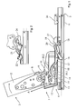
- the vehicle seat 1 illustrated in the figures comprises a backrest structure 2 for the backrest 3 and a rudimentary seat structure 4 for the seat part.
- the seat structure 4 is displaceably arranged on a rail system 5 with a lower rail 6 and an upper rail 7 along a first axis X in and against the direction of travel (-X / X direction of the vehicle).
- the backrest 3 is about an axis of rotation 8 from its slightly reclined position of use ( Fig. 1 ) forward (arrow B) in a forward inclined non-use position ( Fig. 3 and 4 ) pivotable.
- the backrest structure 2 is rotatably connected to a below the axis of rotation 8 downwardly projecting lever 9, which in turn is provided with a laterally projecting pin 10.
- the seat structure 4 has a fitting plate 12, which is pivotable about an axis of rotation 11 and is provided with an arcuate, open-ended link 13.
- the axis of rotation 11 is located at the front end of the fitting plate 12, the rear end by means of a force from their in Fig. 1 shown starting position in the direction of arrow A in the in Fig. 3 and 4 shown functional position can be raised.
- the force means may consist, for example, of a Bowden cable operatively connected to a handle.
- the link 13 In the raised position of the fitting plate 12, the link 13 extends coaxially to the axis of rotation 8 of the backrest 3 with a radius which corresponds to the distance between the axis of rotation 8 and bolt 10.
- the backrest 3 When lifting the fitting plate 12, the backrest 3 is unlocked and can be pivoted about the axis of rotation 8 to the front, wherein the bolt 10 enters the slot 13 and 13 limits the pivotal movement with reaching the end of the slide (see Fig. 3 ).
- an angle piece 14 is also rotatably mounted about an axis of rotation 15, which has two projecting from the axis of rotation 15 legs 16.1, 16.2.
- the legs 16.1, 16.2 close in the embodiment an angle of about 125 °, wherein the leg 16.1 in the in Fig. 1 shown starting position protrudes approximately horizontally forward, while the leg 16.2 is directed obliquely upwards and backwards, thereby partially covering the front part of the gate 13.
- the angle piece 14 by contact of the bolt 10 with the leg 16.2 to the rear (in the view on the left side of the seat Fig. 1 ie counterclockwise), whereby the forwardly directed leg 16.1 is raised ( Fig. 3 ).
- the leg 16.1 acts on a further lever 17 which is rotatably mounted about an axis of rotation 18 on the upper rail 7 and unlocks the rail lock 19 when actuated.
- the vehicle seat 1 can now move from the intermediate position Fig. 3 in the access position Fig. 4 to be moved forward.
- a located on the front leg of the lever 17 locking bolt 20 acts in the front end position on a latch 26, which holds the vehicle seat 1 releasably in the access position.
- the locking bolt 20 is disengaged from the detent 26.
- a rotary lever 22 rotatably mounted on the seat structure 4 (FIG. Fig.
Landscapes
- Engineering & Computer Science (AREA)
- Aviation & Aerospace Engineering (AREA)
- Transportation (AREA)
- Mechanical Engineering (AREA)
- Seats For Vehicles (AREA)
Description
- Die Erfindung betrifft einen Fahrzeugsitz, insbesondere für ein Kraftfahrzeug, mit mindestens einer Gebrauchsstellung und einer den Zugang zu einem dahinter angeordneten weiteren Fahrzeugsitz erleichternden Zugangsstellung (Easy-Entry-Position).
- Ein derartiger Sitz ist nach dem Oberbegriff des Anspruchs 1 aus der
FR 2 867 428 A1 - Der Erfindung liegt die Aufgabe zugrunde, eine sichere und weit öffnende Zugangsstellung mit einfachen Mitteln bereitzustellen.
- Gelöst wird diese Aufgabe erfindungsgemäß durch einen Fahrzeugsitz nach Anspruch 1.
- Bevorzugt ist vorgesehen, dass die Raste des Sitzes an einer Unterschiene angeordnet ist, wobei die Unterschiene an einer Bodenstruktur eines Kraftfahrzeugs befestigbar ist. Dadurch ist vorteilhaft eine besonders einfache Integration des Verschiebungsbegrenzungsmittels in ein herkömmliches Schienensystem mit Oberschiene und Unterschiene möglich.
- Bevorzugt ist vorgesehen, dass der drehbare Hebel des Sitzes an einem Entriegelungsmittel angeordnet ist, wobei der Fahrzeugsitz zur Überführung aus der Gebrauchsstellung in die Zugangsstellung durch das Entriegelungsmittel entriegelbar ist. Dadurch ist vorteilhaft keine Anordnung des Verschiebungsbegrenzungsmittels im Innem der Unter- und Oberschiene notwendig, sodass eine vergleichsweise einfache Realisierung der Verschiebungsbegrenzung möglich ist.
- Bevorzugt ist vorgesehen, dass das Entriegelungsmittel durch ein Kraftmittel betätigbar ist, wobei das Kraftmittel bevorzugt eine Handhabe mit einem Seilzug aufweist. Dadurch ist vorteilhaft eine besonders einfache und kostengünstige Betätigung des Entriegelungsmittels möglich.
- Bevorzugt ist vorgesehen, dass die Verriegelung in der Zugangsstellung durch Zurückziehen des Fahrzeugsitzes entriegelbar ist. Dadurch ist vorteilhaft eine besonders komfortable Entriegelung durch den auf der Rücksitzbank sitzenden Insassen möglich.
- Bevorzugt ist vorgesehen, dass die Rückenlehne beim Überführen des Fahrzeugsitzes aus der Gebrauchsstellung in die Zugangsstellung auf die Sitzstruktur schwenkbar ist. Dadurch ist vorteilhaft ein größerer Zugangsraum für die Insassen erreichbar.
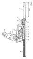
- Die Figuren stellen beispielhaft und schematisch eine Ausführung der Erfindung dar.
- Es zeigen:
- Figur 1
- eine seitliche Ansicht der Struktur eines erfindungsgemäßen Fahrzeugsitzes in Gebrauchsstellung;
- Figur 2
- den in
Fig. 1 gezeigten Mechanismus in rückseitiger Ansicht; - Figur 3
- den Fahrzeugsitz nach
Fig. 1 in einer Zwischenstellung; - Figur 4
- den Fahrzeugsitz nach
Fig. 1 in Zugangsstellung (Easy-Entry). - Der in den Figuren dargestellte Fahrzeugsitz 1 umfasst eine Lehnenstruktur 2 für die Rückenlehne 3 und eine rudimentär dargestellte Sitzstruktur 4 für das Sitzteil. Die Sitzstruktur 4 ist auf einem Schienensystem 5 mit einer Unterschiene 6 und einer Oberschiene 7 entlang einer ersten Achse X in und gegen die Fahrtrichtung (-X/X-Richtung des Fahrzeugs) verschieblich angeordnet.
- Die Rückenlehne 3 ist um eine Drehachse 8 aus ihrer leicht nach hinten geneigten Gebrauchsstellung (
Fig. 1 ) nach vorne (Pfeil B) in eine nach vorne geneigte Nichtgebrauchstellung (Fig. 3 und4 ) schwenkbar. Die Lehnenstruktur 2 ist drehfest mit einem unterhalb der Drehachse 8 nach unten auskragenden Hebel 9 verbunden, der seinerseits mit einem seitlich auskragenden Bolzen 10 versehen ist. - Die Sitzstruktur 4 weist eine um eine Drehachse 11 schwenkbare Beschlagplatte 12 auf, die mit einer bogenförmigen, nach vorne offenen Kulisse 13 ausgestattet ist. Die Drehachse 11 befindet sich am vorderen Ende der Beschlagplatte 12, deren hinteres Ende mittels eines Kraftmittels aus ihrer in
Fig. 1 gezeigten Ausgangsstellung in Richtung des Pfeils A in die inFig. 3 und4 gezeigte Funktionsstellung angehoben werden kann. Das Kraftmittel kann beispielsweise aus einem mit einer Handhabe wirkverbundenen Bowdenzug bestehen. In angehobener Stellung der Beschlagplatte 12 verläuft die Kulisse 13 koaxial zur Drehachse 8 der Rückenlehne 3 mit einem Radius, welcher dem Abstand zwischen Drehachse 8 und Bolzen 10 entspricht. - Beim Anheben der Beschlagplatte 12 wird die Rückenlehne 3 entriegelt und kann um die Drehachse 8 nach vorne geschwenkt werden, wobei der Bolzen 10 in die Kulisse 13 einläuft und mit Erreichen des Endes der Kulisse 13 die Schwenkbewegung begrenzt (siehe
Fig. 3 ). - An der Beschlagplatte 12 ist ferner ein Winkelstück 14 um eine Drehachse 15 drehbar gelagert, das zwei von der Drehachse 15 abragende Schenkel 16.1, 16.2 aufweist. Die Schenkel 16.1, 16.2 schließen im Ausführungsbeispiel einen Winkel von von etwa 125° ein, wobei der Schenkel 16.1 in der in
Fig. 1 gezeigten Ausgangsstellung etwa waagerecht nach vorne ragt, während der Schenkel 16.2 schräg nach oben und hinten gerichtet ist und dabei den vorderen Teil der Kulisse 13 teilweise überdeckt. Beim Vorklappen der Rückenlehne wird das Winkelstück 14 durch Kontakt des Bolzens 10 mit dem Schenkel 16.2 nach hinten (in der Ansicht auf die linke Sitzseite nachFig. 1 also gegen den Uhrzeigersinn) verdreht, wobei der nach vorne gerichtete Schenkel 16.1 angehoben wird (Fig. 3 ). Dabei wirkt der Schenkel 16.1 auf einen weiteren Hebel 17 ein, der um eine Drehachse 18 drehbar an der Oberschiene 7 gelagert ist und bei Betätigung die Schienenverriegelung 19 entsperrt. Der Fahrzeugsitz 1 kann nun aus der Zwischenstellung nachFig. 3 in die Zugangsstellung nachFig. 4 nach vorne verschoben werden. Ein am vorderen Schenkel des Hebels 17 befindlicher Verriegelungsbolzen 20 wirkt dabei in vorderer Endstellung auf auf eine Raste 26 ein, welche den Fahrzeugsitz 1 lösbar in der Zugangsstellung hält. Beim Zurückziehen des Fahrzeugsitzes 1 gerät der Verriegelungsbolzen 20 außer Eingriff mit der Raste 26. Ferner kommt ein an der Sitzstruktur 4 drehbar gelagerter Drehhebel 22 (Fig. 2 ) in Kontakt mit einer beidseits rampenförmig ausgebildeten Nockenplatte 27. Der Kontur der Nockenplatte 27 folgend wird der Drehhebel 22 verdreht und verlagert dabei eine Übertragungsstange 23, welche mit ihrem anderen Ende gegensinnig auf einen schwenkbaren Sperrnocken 24 wirkt. Der Spermocken 24 sperrt den Bolzen 10 bei vorgeklappter Rückenlehne 3 in der Kulisse 13, so dass ein Zurückklappen der Rückenlehne 3 erst dann möglich ist, wenn der Fahrzeugsitz 1 wieder zurückgezogen worden ist. Alle Komponenten drehen nun in die Ausgangsstellung nachFig. 1 zurück. -
- 1
- Fahrzeugsitz
- 2
- Lehnenstruktur
- 3
- Rückenlehne
- 4
- Sitzstruktur
- 5
- Schienensystem
- 6
- Unterschiene
- 7
- Oberschiene
- 8
- Drehachse
- 9
- Hebel
- 10
- Bolzen
- 11
- Drehachse
- 12
- Beschlagplatte
- 13
- Kulisse
- 14
- Winkelstück
- 15
- Drehachse
- 16.1, 16.2
- Schenkel
- 17
- Hebel
- 18
- Drehachse
- 19
- Schienenverriegelung
- 20
- Verriegelungsbolzen
- 21
- Aktuierungshebel
- 22
- Drehhebel
- 23
- Übertragungsstange
- 24
- Spermocken
- 25
- Nockenplatte
- 26
- Raste
- 27
- Nockenplatte
Claims (6)
- Fahrzeugsitz (1), wobei der Fahrzeugsitz (1) aus einer Gebrauchsstellung in eine Zugangsstellung überführbar ist, wobei der Fahrzeugsitz (1) eine Lehnenstruktur (2) für die Rückenlehne (3) und eine Sitzstruktur (4) aufweist, wobei der Fahrzeugsitz (1) entlang einer Achse (X) verschieblich auf einem eine Oberschiene (7) und eine Unterschiene (6) umfassenden Schienensystem (5) gelagert ist, dadurch gekennzeichnet, dass der Fahrzeugsitz (1) ein Verschiebungsbegrenzungsmittel aufweist, wobei das Verschiebungsbegrenzungsmittel eine Verschiebung des Fahrzeugsitzes (1) entlang der Achse (X) beim Überführen des Fahrzeugsitzes (1) aus der Gebrauchsstellung in die Zugangsstellung begrenzt, wobei wobei der Fahrzeugsitz (1) in der Zugangsstellung durch das Verschiebungsbegrenzungsmittel verriegelbar ist, wobei das Verschiebungsbegrenzungsmittel eine Raste (26) und einen Verriegelungsbolzen (20) aufweist, wobei in der Zugangsstellung die Raste (26) mit dem Verriegelungsbolzen (20) zusammenwirkt,
dadurch gekennzeichnet, dass
der Fahrzeugsitz einen an der Oberschiene (7) gelagerten und um eine Drehachse (18) zwischen einem vorderen und einem hinteren Schenkel drehbaren Hebel (17) aufweist, der bei Betätigung eine Schienenverriegelung (19) des Fahrzeugsitzes (1) entsperrt, wobei am vorderen Schenkel des Hebels (17) der Verriegelungsbolzen (20) angeordnet ist und in der Zugangsstellung auf die Raste (26) einwirkt. - Fahrzeugsitz (1) nach Anspruch 1, dadurch gekennzeichnet, dass die Raste (26) an der Unterschiene (6) angeordnet ist, wobei die Unterschiene (6) an einer Bodenstruktur eines Kraftfahrzeugs befestigbar ist.
- Fahrzeugsitz (1) nach einem der vorhergehenden Ansprüche, dadurch gekennzeichnet, dass der drehbare Hebel (17) an einem Entriegelungsmittel angeordnet ist, wobei der Fahrzeugsitz (1) zur Überführung aus der Gebrauchsstellung in die Zugangsstellung durch das Entriegelungsmittel entriegelbar ist.
- Fahrzeugsitz (1) nach Anspruch 3, dadurch gekennzeichnet, dass das Entriegelungsmittel durch ein Kraftmittel betätigbar ist, wobei das Kraftmittel bevorzugt eine Handhabe mit einem Seilzug aufweist.
- Fahrzeugsitz (1) nach einem der vorhergehenden Ansprüche, dadurch gekennzeichnet, dass die Verriegelung in der Zugangsstellung durch Zurückziehen des Fahrzeugsitzes (1) entriegelbar ist.
- Fahrzeugsitz (1) nach einem der vorhergehenden Ansprüche, dadurch gekennzeichnet, dass die Rückenlehne (3) beim Überführen des Fahrzeugsitzes (1) aus der Gebrauchsstellung in die Zugangsstellung auf die Sitzstruktur (4) schwenkbar ist.
Applications Claiming Priority (1)
| Application Number | Priority Date | Filing Date | Title |
|---|---|---|---|
| DE102009040750 | 2009-09-10 |
Publications (3)
| Publication Number | Publication Date |
|---|---|
| EP2295284A2 EP2295284A2 (de) | 2011-03-16 |
| EP2295284A3 EP2295284A3 (de) | 2012-12-19 |
| EP2295284B1 true EP2295284B1 (de) | 2016-10-05 |
Family
ID=43303868
Family Applications (1)
| Application Number | Title | Priority Date | Filing Date |
|---|---|---|---|
| EP10009381.4A Not-in-force EP2295284B1 (de) | 2009-09-10 | 2010-09-09 | Fahrzeugsitz |
Country Status (1)
| Country | Link |
|---|---|
| EP (1) | EP2295284B1 (de) |
Families Citing this family (3)
| Publication number | Priority date | Publication date | Assignee | Title |
|---|---|---|---|---|
| DE102013214175B4 (de) * | 2013-04-30 | 2014-11-06 | Johnson Controls Components Gmbh & Co. Kg | Längseinstellbarer fahrzeugsitz |
| DE102016204645B4 (de) * | 2015-11-30 | 2023-05-17 | Adient Us Llc | Fahrzeugsitz, insbesondere kraftfahrzeugsitz |
| DE102020118582A1 (de) * | 2020-07-14 | 2022-01-20 | Faurecia Autositze Gmbh | Verstellbarer kraftfahrzeugsitz |
Family Cites Families (2)
| Publication number | Priority date | Publication date | Assignee | Title |
|---|---|---|---|---|
| DE102004057106B4 (de) * | 2004-03-11 | 2018-03-08 | Adient Luxembourg Holding S.à.r.l. | Vorverlagerbarer Kraftfahrzeugsitz |
| FR2888539B1 (fr) * | 2005-07-12 | 2008-11-07 | Faurecia Sieges Automobile | Siege de vehicule coulissant et glissiere pour un tel siege |
-
2010
- 2010-09-09 EP EP10009381.4A patent/EP2295284B1/de not_active Not-in-force
Also Published As
| Publication number | Publication date |
|---|---|
| EP2295284A3 (de) | 2012-12-19 |
| EP2295284A2 (de) | 2011-03-16 |
Similar Documents
| Publication | Publication Date | Title |
|---|---|---|
| DE69902629T2 (de) | Drehgelenkmechanismus für multifunktionelle anwendungen an einem kraftfahrzeugsitz | |
| DE10339788B4 (de) | Flach zusammenfaltbarer Fahrzeugsitz | |
| EP1915275B1 (de) | Lehnenklappung | |
| EP3325310B1 (de) | Fahrzeugsitz | |
| EP2768697B1 (de) | Verriegelungs- und neigungsverstellanordnung, insbesondere lehnenschloss | |
| DE102013215028B4 (de) | Easy-Entry-System für einen Fahrzeugsitz und Fahrzeugsitz | |
| EP3033247A1 (de) | Easy-entry-verstellmechanismus für dive-down-fahrzeugsitze beziehungsweise sitzanlagen | |
| EP3077249B1 (de) | Vorschwenkmechanismus für einen fahrzeugsitz und fahrzeugsitz | |
| WO2016001096A1 (de) | Lehnenversteller für einen sitz und fahrzeugsitz | |
| DE102008006980A1 (de) | Fahrzeugsitzeinrichtung | |
| DE102007029495B4 (de) | Fahrzeugsitz | |
| DE102013221925B3 (de) | Beschlag mit einem Vorschwenkmechanismus und einer Easy-Entry-Klinke, Easy-Entry-Klinke für einen solchen Beschlag sowie Fahrzeugsitz mit einem solchen Beschlag | |
| EP3162620B1 (de) | Längseinsteller für einen fahrzeugsitz, fahrzeugsitz | |
| DE10313807B4 (de) | Fahrzeugsitz | |
| DE10207179C1 (de) | Fahrzeugsitz | |
| DE102006001530B4 (de) | Kraftfahrzeugsitz mit Easy-Entry-Funktion | |
| WO2008116436A1 (de) | Fahrzeugsitz | |
| EP3694744B1 (de) | Fahrzeugsitz mit einem easy-entry-mechanismus | |
| DE102009035229A1 (de) | Verstellvorrichtung für die Rückenlehne eines Fahrzeugsitzes, Fahr-zeugsitz mit einer solchen Verstellvorrichtung und Sitzanordnung mit einem solchen Fahrzeugsitz | |
| EP2295284A2 (de) | Fahrzeugsitz | |
| DE102010045418A1 (de) | Schwenksitz | |
| DE102013000164B4 (de) | Fahrzeugsitz, insbesondere für einen Pkw | |
| DE102004002144B4 (de) | Fahrzeugsitz | |
| DE102010021538A1 (de) | Fahrzeugsitz, insbesondere Kraftfahrzeugsitz | |
| WO2017092910A1 (de) | Fahrzeugsitz, insbesondere kraftfahrzeugsitz |
Legal Events
| Date | Code | Title | Description |
|---|---|---|---|
| PUAI | Public reference made under article 153(3) epc to a published international application that has entered the european phase |
Free format text: ORIGINAL CODE: 0009012 |
|
| AK | Designated contracting states |
Kind code of ref document: A2 Designated state(s): AL AT BE BG CH CY CZ DE DK EE ES FI FR GB GR HR HU IE IS IT LI LT LU LV MC MK MT NL NO PL PT RO SE SI SK SM TR |
|
| AX | Request for extension of the european patent |
Extension state: BA ME RS |
|
| PUAL | Search report despatched |
Free format text: ORIGINAL CODE: 0009013 |
|
| AK | Designated contracting states |
Kind code of ref document: A3 Designated state(s): AL AT BE BG CH CY CZ DE DK EE ES FI FR GB GR HR HU IE IS IT LI LT LU LV MC MK MT NL NO PL PT RO SE SI SK SM TR |
|
| AX | Request for extension of the european patent |
Extension state: BA ME RS |
|
| RIC1 | Information provided on ipc code assigned before grant |
Ipc: B60N 2/07 20060101AFI20121115BHEP Ipc: B60N 2/12 20060101ALI20121115BHEP |
|
| 17P | Request for examination filed |
Effective date: 20130619 |
|
| RBV | Designated contracting states (corrected) |
Designated state(s): AL AT BE BG CH CY CZ DE DK EE ES FI FR GB GR HR HU IE IS IT LI LT LU LV MC MK MT NL NO PL PT RO SE SI SK SM TR |
|
| 17Q | First examination report despatched |
Effective date: 20131213 |
|
| GRAP | Despatch of communication of intention to grant a patent |
Free format text: ORIGINAL CODE: EPIDOSNIGR1 |
|
| INTG | Intention to grant announced |
Effective date: 20160406 |
|
| GRAS | Grant fee paid |
Free format text: ORIGINAL CODE: EPIDOSNIGR3 |
|
| GRAA | (expected) grant |
Free format text: ORIGINAL CODE: 0009210 |
|
| AK | Designated contracting states |
Kind code of ref document: B1 Designated state(s): AL AT BE BG CH CY CZ DE DK EE ES FI FR GB GR HR HU IE IS IT LI LT LU LV MC MK MT NL NO PL PT RO SE SI SK SM TR |
|
| REG | Reference to a national code |
Ref country code: GB Ref legal event code: FG4D Free format text: NOT ENGLISH |
|
| REG | Reference to a national code |
Ref country code: CH Ref legal event code: EP |
|
| REG | Reference to a national code |
Ref country code: AT Ref legal event code: REF Ref document number: 834301 Country of ref document: AT Kind code of ref document: T Effective date: 20161015 |
|
| REG | Reference to a national code |
Ref country code: IE Ref legal event code: FG4D Free format text: LANGUAGE OF EP DOCUMENT: GERMAN |
|
| REG | Reference to a national code |
Ref country code: DE Ref legal event code: R096 Ref document number: 502010012498 Country of ref document: DE |
|
| REG | Reference to a national code |
Ref country code: NL Ref legal event code: MP Effective date: 20161005 |
|
| REG | Reference to a national code |
Ref country code: LT Ref legal event code: MG4D |
|
| PG25 | Lapsed in a contracting state [announced via postgrant information from national office to epo] |
Ref country code: LV Free format text: LAPSE BECAUSE OF FAILURE TO SUBMIT A TRANSLATION OF THE DESCRIPTION OR TO PAY THE FEE WITHIN THE PRESCRIBED TIME-LIMIT Effective date: 20161005 |
|
| PG25 | Lapsed in a contracting state [announced via postgrant information from national office to epo] |
Ref country code: NO Free format text: LAPSE BECAUSE OF FAILURE TO SUBMIT A TRANSLATION OF THE DESCRIPTION OR TO PAY THE FEE WITHIN THE PRESCRIBED TIME-LIMIT Effective date: 20170105 Ref country code: GR Free format text: LAPSE BECAUSE OF FAILURE TO SUBMIT A TRANSLATION OF THE DESCRIPTION OR TO PAY THE FEE WITHIN THE PRESCRIBED TIME-LIMIT Effective date: 20170106 Ref country code: LT Free format text: LAPSE BECAUSE OF FAILURE TO SUBMIT A TRANSLATION OF THE DESCRIPTION OR TO PAY THE FEE WITHIN THE PRESCRIBED TIME-LIMIT Effective date: 20161005 Ref country code: SE Free format text: LAPSE BECAUSE OF FAILURE TO SUBMIT A TRANSLATION OF THE DESCRIPTION OR TO PAY THE FEE WITHIN THE PRESCRIBED TIME-LIMIT Effective date: 20161005 |
|
| PG25 | Lapsed in a contracting state [announced via postgrant information from national office to epo] |
Ref country code: PL Free format text: LAPSE BECAUSE OF FAILURE TO SUBMIT A TRANSLATION OF THE DESCRIPTION OR TO PAY THE FEE WITHIN THE PRESCRIBED TIME-LIMIT Effective date: 20161005 Ref country code: IS Free format text: LAPSE BECAUSE OF FAILURE TO SUBMIT A TRANSLATION OF THE DESCRIPTION OR TO PAY THE FEE WITHIN THE PRESCRIBED TIME-LIMIT Effective date: 20170205 Ref country code: FI Free format text: LAPSE BECAUSE OF FAILURE TO SUBMIT A TRANSLATION OF THE DESCRIPTION OR TO PAY THE FEE WITHIN THE PRESCRIBED TIME-LIMIT Effective date: 20161005 Ref country code: NL Free format text: LAPSE BECAUSE OF FAILURE TO SUBMIT A TRANSLATION OF THE DESCRIPTION OR TO PAY THE FEE WITHIN THE PRESCRIBED TIME-LIMIT Effective date: 20161005 Ref country code: PT Free format text: LAPSE BECAUSE OF FAILURE TO SUBMIT A TRANSLATION OF THE DESCRIPTION OR TO PAY THE FEE WITHIN THE PRESCRIBED TIME-LIMIT Effective date: 20170206 Ref country code: ES Free format text: LAPSE BECAUSE OF FAILURE TO SUBMIT A TRANSLATION OF THE DESCRIPTION OR TO PAY THE FEE WITHIN THE PRESCRIBED TIME-LIMIT Effective date: 20161005 Ref country code: HR Free format text: LAPSE BECAUSE OF FAILURE TO SUBMIT A TRANSLATION OF THE DESCRIPTION OR TO PAY THE FEE WITHIN THE PRESCRIBED TIME-LIMIT Effective date: 20161005 |
|
| REG | Reference to a national code |
Ref country code: DE Ref legal event code: R097 Ref document number: 502010012498 Country of ref document: DE |
|
| PG25 | Lapsed in a contracting state [announced via postgrant information from national office to epo] |
Ref country code: EE Free format text: LAPSE BECAUSE OF FAILURE TO SUBMIT A TRANSLATION OF THE DESCRIPTION OR TO PAY THE FEE WITHIN THE PRESCRIBED TIME-LIMIT Effective date: 20161005 Ref country code: DK Free format text: LAPSE BECAUSE OF FAILURE TO SUBMIT A TRANSLATION OF THE DESCRIPTION OR TO PAY THE FEE WITHIN THE PRESCRIBED TIME-LIMIT Effective date: 20161005 Ref country code: CZ Free format text: LAPSE BECAUSE OF FAILURE TO SUBMIT A TRANSLATION OF THE DESCRIPTION OR TO PAY THE FEE WITHIN THE PRESCRIBED TIME-LIMIT Effective date: 20161005 Ref country code: RO Free format text: LAPSE BECAUSE OF FAILURE TO SUBMIT A TRANSLATION OF THE DESCRIPTION OR TO PAY THE FEE WITHIN THE PRESCRIBED TIME-LIMIT Effective date: 20161005 Ref country code: SK Free format text: LAPSE BECAUSE OF FAILURE TO SUBMIT A TRANSLATION OF THE DESCRIPTION OR TO PAY THE FEE WITHIN THE PRESCRIBED TIME-LIMIT Effective date: 20161005 |
|
| PLBE | No opposition filed within time limit |
Free format text: ORIGINAL CODE: 0009261 |
|
| STAA | Information on the status of an ep patent application or granted ep patent |
Free format text: STATUS: NO OPPOSITION FILED WITHIN TIME LIMIT |
|
| PG25 | Lapsed in a contracting state [announced via postgrant information from national office to epo] |
Ref country code: BG Free format text: LAPSE BECAUSE OF FAILURE TO SUBMIT A TRANSLATION OF THE DESCRIPTION OR TO PAY THE FEE WITHIN THE PRESCRIBED TIME-LIMIT Effective date: 20170105 Ref country code: IT Free format text: LAPSE BECAUSE OF FAILURE TO SUBMIT A TRANSLATION OF THE DESCRIPTION OR TO PAY THE FEE WITHIN THE PRESCRIBED TIME-LIMIT Effective date: 20161005 Ref country code: SM Free format text: LAPSE BECAUSE OF FAILURE TO SUBMIT A TRANSLATION OF THE DESCRIPTION OR TO PAY THE FEE WITHIN THE PRESCRIBED TIME-LIMIT Effective date: 20161005 |
|
| 26N | No opposition filed |
Effective date: 20170706 |
|
| REG | Reference to a national code |
Ref country code: FR Ref legal event code: PLFP Year of fee payment: 8 |
|
| PG25 | Lapsed in a contracting state [announced via postgrant information from national office to epo] |
Ref country code: SI Free format text: LAPSE BECAUSE OF FAILURE TO SUBMIT A TRANSLATION OF THE DESCRIPTION OR TO PAY THE FEE WITHIN THE PRESCRIBED TIME-LIMIT Effective date: 20161005 |
|
| REG | Reference to a national code |
Ref country code: CH Ref legal event code: PL |
|
| GBPC | Gb: european patent ceased through non-payment of renewal fee |
Effective date: 20170909 |
|
| PG25 | Lapsed in a contracting state [announced via postgrant information from national office to epo] |
Ref country code: MC Free format text: LAPSE BECAUSE OF FAILURE TO SUBMIT A TRANSLATION OF THE DESCRIPTION OR TO PAY THE FEE WITHIN THE PRESCRIBED TIME-LIMIT Effective date: 20161005 |
|
| REG | Reference to a national code |
Ref country code: IE Ref legal event code: MM4A |
|
| REG | Reference to a national code |
Ref country code: BE Ref legal event code: MM Effective date: 20170930 |
|
| PG25 | Lapsed in a contracting state [announced via postgrant information from national office to epo] |
Ref country code: LU Free format text: LAPSE BECAUSE OF NON-PAYMENT OF DUE FEES Effective date: 20170909 |
|
| PG25 | Lapsed in a contracting state [announced via postgrant information from national office to epo] |
Ref country code: GB Free format text: LAPSE BECAUSE OF NON-PAYMENT OF DUE FEES Effective date: 20170909 Ref country code: LI Free format text: LAPSE BECAUSE OF NON-PAYMENT OF DUE FEES Effective date: 20170930 Ref country code: IE Free format text: LAPSE BECAUSE OF NON-PAYMENT OF DUE FEES Effective date: 20170909 Ref country code: CH Free format text: LAPSE BECAUSE OF NON-PAYMENT OF DUE FEES Effective date: 20170930 |
|
| PG25 | Lapsed in a contracting state [announced via postgrant information from national office to epo] |
Ref country code: BE Free format text: LAPSE BECAUSE OF NON-PAYMENT OF DUE FEES Effective date: 20170930 |
|
| REG | Reference to a national code |
Ref country code: FR Ref legal event code: PLFP Year of fee payment: 9 |
|
| PG25 | Lapsed in a contracting state [announced via postgrant information from national office to epo] |
Ref country code: MT Free format text: LAPSE BECAUSE OF FAILURE TO SUBMIT A TRANSLATION OF THE DESCRIPTION OR TO PAY THE FEE WITHIN THE PRESCRIBED TIME-LIMIT Effective date: 20161005 |
|
| REG | Reference to a national code |
Ref country code: AT Ref legal event code: MM01 Ref document number: 834301 Country of ref document: AT Kind code of ref document: T Effective date: 20170909 |
|
| PG25 | Lapsed in a contracting state [announced via postgrant information from national office to epo] |
Ref country code: AT Free format text: LAPSE BECAUSE OF NON-PAYMENT OF DUE FEES Effective date: 20170909 |
|
| PG25 | Lapsed in a contracting state [announced via postgrant information from national office to epo] |
Ref country code: HU Free format text: LAPSE BECAUSE OF FAILURE TO SUBMIT A TRANSLATION OF THE DESCRIPTION OR TO PAY THE FEE WITHIN THE PRESCRIBED TIME-LIMIT; INVALID AB INITIO Effective date: 20100909 |
|
| REG | Reference to a national code |
Ref country code: DE Ref legal event code: R081 Ref document number: 502010012498 Country of ref document: DE Owner name: ADIENT US LLC, PLYMOUTH, US Free format text: FORMER OWNER: JOHNSON CONTROLS GMBH, 51399 BURSCHEID, DE Ref country code: DE Ref legal event code: R081 Ref document number: 502010012498 Country of ref document: DE Owner name: ADIENT LUXEMBOURG HOLDING S.A R.L., LU Free format text: FORMER OWNER: JOHNSON CONTROLS GMBH, 51399 BURSCHEID, DE |
|
| PG25 | Lapsed in a contracting state [announced via postgrant information from national office to epo] |
Ref country code: CY Free format text: LAPSE BECAUSE OF NON-PAYMENT OF DUE FEES Effective date: 20161005 |
|
| PG25 | Lapsed in a contracting state [announced via postgrant information from national office to epo] |
Ref country code: MK Free format text: LAPSE BECAUSE OF FAILURE TO SUBMIT A TRANSLATION OF THE DESCRIPTION OR TO PAY THE FEE WITHIN THE PRESCRIBED TIME-LIMIT Effective date: 20161005 |
|
| PG25 | Lapsed in a contracting state [announced via postgrant information from national office to epo] |
Ref country code: TR Free format text: LAPSE BECAUSE OF FAILURE TO SUBMIT A TRANSLATION OF THE DESCRIPTION OR TO PAY THE FEE WITHIN THE PRESCRIBED TIME-LIMIT Effective date: 20161005 |
|
| PG25 | Lapsed in a contracting state [announced via postgrant information from national office to epo] |
Ref country code: AL Free format text: LAPSE BECAUSE OF FAILURE TO SUBMIT A TRANSLATION OF THE DESCRIPTION OR TO PAY THE FEE WITHIN THE PRESCRIBED TIME-LIMIT Effective date: 20161005 |
|
| REG | Reference to a national code |
Ref country code: DE Ref legal event code: R082 Ref document number: 502010012498 Country of ref document: DE Representative=s name: LIEDHEGENER, RALF, DIPL.-ING., DE |
|
| REG | Reference to a national code |
Ref country code: DE Ref legal event code: R081 Ref document number: 502010012498 Country of ref document: DE Owner name: ADIENT US LLC, PLYMOUTH, US Free format text: FORMER OWNER: ADIENT LUXEMBOURG HOLDING S.A R.L., LUXEMBOURG, LU |
|
| PGFP | Annual fee paid to national office [announced via postgrant information from national office to epo] |
Ref country code: DE Payment date: 20220928 Year of fee payment: 13 |
|
| PGFP | Annual fee paid to national office [announced via postgrant information from national office to epo] |
Ref country code: FR Payment date: 20220926 Year of fee payment: 13 |
|
| REG | Reference to a national code |
Ref country code: DE Ref legal event code: R119 Ref document number: 502010012498 Country of ref document: DE |
|
| PG25 | Lapsed in a contracting state [announced via postgrant information from national office to epo] |
Ref country code: FR Free format text: LAPSE BECAUSE OF NON-PAYMENT OF DUE FEES Effective date: 20230930 Ref country code: DE Free format text: LAPSE BECAUSE OF NON-PAYMENT OF DUE FEES Effective date: 20240403 |