EP2294956A1 - Schneidbrett für Haushaltszwecke - Google Patents
Schneidbrett für Haushaltszwecke Download PDFInfo
- Publication number
- EP2294956A1 EP2294956A1 EP10401156A EP10401156A EP2294956A1 EP 2294956 A1 EP2294956 A1 EP 2294956A1 EP 10401156 A EP10401156 A EP 10401156A EP 10401156 A EP10401156 A EP 10401156A EP 2294956 A1 EP2294956 A1 EP 2294956A1
- Authority
- EP
- European Patent Office
- Prior art keywords
- cutting surface
- collecting container
- cutting
- chopping board
- spacer elements
- Prior art date
- Legal status (The legal status is an assumption and is not a legal conclusion. Google has not performed a legal analysis and makes no representation as to the accuracy of the status listed.)
- Granted
Links
Images

Classifications
-
- A—HUMAN NECESSITIES
- A47—FURNITURE; DOMESTIC ARTICLES OR APPLIANCES; COFFEE MILLS; SPICE MILLS; SUCTION CLEANERS IN GENERAL
- A47J—KITCHEN EQUIPMENT; COFFEE MILLS; SPICE MILLS; APPARATUS FOR MAKING BEVERAGES
- A47J47/00—Kitchen containers, stands or the like, not provided for in other groups of this subclass; Cutting-boards, e.g. for bread
- A47J47/005—Cutting boards
Definitions
- the invention relates to a cutting board for household purposes according to the preamble of claim 1.
- Chopping boards for household purposes are known in various embodiments. They are made of different materials and differ in their shape and size. A common feature of the cutting boards is that they have a flat surface for cutting or otherwise processing food such as food. Meat, vegetables, herbs, fruits, bread products and other foods. Conventional cutting boards offer the possibility of storing the cut or processed food in an edge area. Other embodiments provide below the cutting surface slidably mounted drip pans, so that over the respective narrow side of the cutting surface either the cut food or waste accumulated can be disposed of.
- a chopping board which has a drawer disposed below the cutting surface for receiving waste.
- This drawer is slidably mounted and is completely withdrawn from the storage to carry the waste incurred during the cutting process by means of the drawer to a waste container and can dispose of.
- the invention has for its object to further develop a cutting board, which has a simple structure and yet takes into account the disadvantages described and in particular the time required when working with a cutting board can be reduced.
- the cutting board according to the invention has at least two spacers below the narrow sides of the cutting surface and the spacer elements each have two opposing guide grooves for receiving at least two receptacles, there is the advantage that transported over the broad side of the cutting surface, the finished clippings as well as the waste in a collecting container can be, without clippings or parts of the waste fall next to the collection container.
- the respectively opposite guide grooves extend to receive the collecting container in a direction parallel to the cutting surface.
- the guide grooves are formed and arranged at such a distance from each other that they standardized in commercial household appliances, especially steamer, use can find using cooking containers, so that the user of the cutting board the finished cut into the arranged below the cutting surface container be able to carry and directly without having to make another Umhellrea that can give finished clippings in the household appliance for further treatment.
- the cutting surface of the cutting board has longitudinal grooves in the edge region of the narrow sides and at least in the edge region of a broad side adjacent to the narrow side, thus ensuring that the liquid emerging from the cut material during the cutting process can not flow out of the cutting surface in an uncontrolled manner.
- the interconnected longitudinal grooves form a U-shaped juice channel.
- foot or support elements are arranged on the undersides of the spacer elements, so that a secure and non-slip stand of the cutting board is ensured on various surfaces. It is also conceivable that the foot or support elements are designed to be height adjustable, so that advantageously in the lower guide grooves deeper-sized collecting container can be stored.
- the cutting board according to the invention and / or the spacer elements may be made of wood, plastic, glass, ceramic, stone or metal.
- the at least one collecting container displaceably mounted in the guide grooves adjacent to the underside of the cutting surface, is designed like a sieve in the bottom region and the collecting container displaceably mounted in the underlying guide grooves is closed in the bottom region, so that the cut material to be cut, such as e.g. Vegetables, fruits, is transported into the upper receptacle and the still exiting juice through the sieve-like bottom area emerge and can be absorbed by the underlying collection container.
- the cut material to be cut such as e.g. Vegetables, fruits
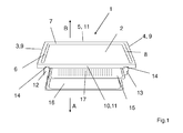
- FIG. 1 shows a first schematically illustrated embodiment of the cutting board 1 according to the invention in a perspective view.
- the cutting board 2 has a rectangular cutting surface 2.
- the cutting surface 2 is formed over the entire surface and smooth and has in the edge region of their narrow sides 3, 4 and in the edge region of the upper broad side 5 interconnected juice channels 6, 7, 8.
- This juice grooves 6, 7, 8 are formed trough-like, form a U-shape and serve to flow over the cutting edge 9 of the narrow sides 3, 4 or on the cutting edge 11 of the upper broad side 5 of the cutting surface 2 liquid can not flow unhindered, the when cutting from the clippings, such as fruit, vegetables or meat can escape.
- the spacer elements 12, 13 are connected via a connection, preferably with a dovetail joint 14 releasably connected to the underside of the cutting surface 2 and point in FIG. 2 Guide grooves to be shown in more detail, in which a first and a second receptacle 15, 16 are slidably mounted. Characterized in that the filling takes place in particular on the broad side 5, 10 of the cutting surface 2, a comparison with the filling of the collecting container 15, 16 on the narrow sides 3, 4 of the cutting surface 2 more uniform filling of the collecting container 15, 16 carried, so that less clippings during Transporting the cuttings of the cutting surface 2 next to the collecting container 15 falls. It is also conceivable that the spacer elements 12, 13 are connected via not shown plug-in connections or the like with the cutting surface 2.
- the collecting container 15, 16 are to the arrows indicated by the arrows A and B wide sides 5, 10 of the cutting board 1 partially or completely withdrawn.
- the size of the guide grooves slidably mounted in the collecting container 15, 16 is fixed by the distance between the guide grooves to each other in length, but the width is variably selectable, so that in the respective opposite guide not only a collecting container 15, 16, but also a plurality, preferably in each case two separate collecting container 15, 16 can be stored. Furthermore, the capacity of the respective collecting container depending on the height distance of the guide grooves have different dimensions.
- a collecting container 15, 16 is mounted in the respective guide grooves, which is dimensioned such that it is completely covered by the cutting surface 2, so that advantageously a collecting container 15, 16 for receiving finished cut and the other collecting container 15, 16th for receiving waste.
- the upper collecting container 15 is partially pulled out of the guide grooves, so that the finished material to be cut can be conveyed over the cutting edge 11 into the withdrawn collecting container 15.
- the upper collecting container 15 is designed in the ground area 17 sieve-like, so that the liquid emerging from the clippings can flow through the bottom area in the arranged below flat-sized collecting container 16.
- Such an embodiment is particularly advantageous if the spacing of the respective guide grooves in height and in width is chosen such that commercially available cooking containers, such as those used in a steamer, can be used as collecting containers 15, 16 beneath the cutting surface 2.
- the collecting container 15, 16 or Gar notioner with the clippings can then be transported for further processing directly into the domestic appliance, not shown, without the user further intermediate steps, such as the otherwise necessary decanting of the finished cuttings from the collecting container 15, 16 in a corresponding cooking container, are necessary.
- the collected in the lower and flatter container 16 can then be easily disposed of by removing the collection container by the user.
- the collecting container 15, 16 are preferably made of plastic or metal.
- the cutting surface 2 has on the narrow sides 3, 4 a projection to the underlying spacer elements 12, 13, so that in addition under the cutting surface edges 9, 11 of the narrow sides 3, 5 more not shown here collecting container for receiving clippings or waste can be placed , It is also conceivable that the supernatant is not present.
- cutting board 1 and / or the spacer elements 12, 13 of wood, plastic, glass, ceramic, stone or metal can be made according to the invention.
- FIG. 2 shows a further schematically illustrated embodiment of the cutting board 1 in a perspective view.
- the cutting surface 2 increasing spacers 12, 13 are connected via a dovetail joint 14 releasably connected thereto.
- foot or support elements 18 are arranged at least in the respective end region, so that a secure and non-slip state of the cutting board 1 is ensured on various surfaces.
- the first pair of parallel opposing guide grooves 19, 21 is disposed directly below the cutting surface 2.
- the two further guide grooves 20,22 are spaced in the lower edge region of the spacer elements 12, 13.
- the guide grooves 19, 20, 21, 22 have been milled into the spacer elements in the present case. It is also conceivable to mount separate guide rails on the spacer elements 12, 13, in which the collecting containers 15, 16 are displaceably mounted.
Landscapes
- Engineering & Computer Science (AREA)
- Food Science & Technology (AREA)
- Devices For Warming Or Keeping Food Or Tableware Hot (AREA)
Abstract
Description
- Die Erfindung bezieht sich auf ein Schneidbrett für Haushaltszwecke nach dem Oberbegriff von Anspruch 1.
- Schneidbretter für Haushaltszwecke sind in verschiedenen Ausführungsformen bekannt. Sie bestehen aus unterschiedlichen Materialien und unterscheiden sich in ihrer Form und Größe. Ein Einheitsmerkmal der Schneidbretter ist darin zu sehen, dass sie eine plane Oberfläche zum Schneiden oder sonstigen Bearbeiten von Lebensmitteln, wie z.B. Fleisch, Gemüse, Kräuter, Obst, Brotwaren und anderer Lebensmittel aufweisen. Übliche Schneidbretter bieten die Möglichkeit, das geschnittene bzw. bearbeitete Lebensmittel in einem Randbereich zu lagern. Andere Ausführungsformen sehen unterhalb der Schneidfläche verschiebbar gelagerte Auffangschalen vor, damit über die jeweilige Schmalseite der Schneidoberfläche entweder das geschnittene Lebensmittel oder die anfallenden Abfälle entsorgt werden können.
- Aus der
DE 20 2006 016 445 U1 ist ein Schneidbrett bekannt, das eine unterhalb der Schneidfläche angeordnete Schublade zum Aufnehmen von Abfall aufweist. Diese Schublade ist verschiebbar gelagert und ist vollständig aus der Lagerung herausziehbar, um den während des Schneidevorgangs anfallenden Abfall mittels der Schublade zu einem Abfallbehälter befördern und entsorgen zu können. - Nachteilig ist, dass bei der Beförderung des fertigen Schnittgutes über die Schmalseiten der Schneidfläche häufig Schnittgutteile neben den unter der Schmalseite angeordneten Sammelbehälter fallen und teilweise nicht mehr nutzbar sind. Zudem bedeutet das Entsorgen solcher Schnittgutteile einen zusätzlichen Zeitaufwand für den Benutzer eines solchen Schneidbretts.
- Demgemäß liegt der Erfindung die Aufgabe zugrunde, ein Schneidbrett derart weiterzuentwickeln, das einen einfachen Aufbau aufweist und dennoch den beschriebenen Nachteilen Rechnung trägt und insbesondere der Zeitaufwand beim Arbeiten mit einem Schneidbrett verringert werden kann.
- Die Aufgabe wird gelöst durch die Merkmale des unabhängigen Anspruchs 1. Weitere vorteilhafte Ausgestaltungen der Erfindungen ergeben sich aus den weiteren Unteransprüchen.
- Indem das erfindungsgemäße Schneidbrett wenigstens zwei Abstandselemente unterhalb der Schmalseiten der Schneidfläche aufweist und die Abstandselemente jeweils zwei sich gegenüberliegende Führungsnuten zur Aufnahme von wenigstens zwei Auffangbehälter aufweisen, besteht der Vorteil, dass über die Breitseite der Schneidfläche das fertige Schnittgut wie auch der Abfall in einem Auffangbehälter befördert werden kann, ohne dass Schnittgutteile oder Teile des Abfalls neben den Auffangbehälter fallen. Um einen konstruktiv einfachen Aufbau des Schneidbretts realisieren zu können, verlaufen die jeweils sich gegenüberliegenden Führungsnuten zur Aufnahme der Auffangbehälter in paralleler Richtung zur Schneidfläche.
- Um die Weiterbehandlung des Schnittgutes und das Entsorgen des Abfalls besonders einfach gestalten zu können, sind die in den Führungsnuten aufgenommenen Auffangbehälter von dem Schneidbrett vollständig entkoppelbar.
- In einer vorteilhaften Weiterbildung der Erfindung sind die Führungsnuten ausgebildet und in einem solchen Abstand zueinander angeordnet, dass sie standardisierte in handelsüblichen Haushaltgeräten, insbesondere Dampfgarer, Verwendung findende Garbehälter aufnehmen können, so dass der Benutzer des Schneidbretts das fertige Schnittgut in den unterhalb der Schneidfläche angeordneten Behälter befördern kann und direkt ohne einen weiteren Umfüllprozess vornehmen zu müssen, das fertige Schnittgut in das Haushaltgerät zur weiteren Behandlung geben kann.
- Dadurch, dass die unterhalb der Schneidfläche angeordneten Abstandselemente lösbar mit dieser verbunden sind, ist in vorteilhafter Weiterbildung der Erfindung eine optimale Reinigung des Schneidbretts gewährleistbar. Die lösbare Verbindung wird in vorteilhafter Weise mittels einer Schwalbenschwanzverbindung realisiert.
- In einer vorteilhaften Weiterbildung der Erfindung weist die Schneidfläche des Schneidbretts im Randbereich der Schmalseiten und wenigstens im Randbereich einer an die Schmalseite angrenzenden Breitseite Längsnuten auf, so ist sichergestellt, dass die während des Schneideprozesses aus dem Schnittgut austretende Flüssigkeit nicht unkontrolliert von der Schneidfläche abfließen kann. Im einfachsten Fall bilden die untereinander verbundenen Längsnuten eine U-förmige Saftrinne.
- Vorzugsweise sind an den Unterseiten der Abstandselemente Fuß- bzw. Stützelemente angeordnet, so dass ein sicherer und rutschfester Stand des Schneidbretts auf diversen Oberflächen gewährleistet ist. Denkbar ist zudem, dass die Fuß- bzw. Stützelemente höhenverstellbar ausgeführt sind, so dass vorteilhaft in den unteren Führungsnuten tiefer dimensionierte Auffangbehälter gelagert werden können.
- Um den verschiedensten praktischen und ästhetischen Einsatzzwecken gerecht zu werden, kann das erfindungsgemäße Schneidbrett und/oder die Abstandselemente aus Holz, Kunststoff, Glas, Keramik, Stein oder Metall hergestellt sein.
- In einer vorteilhaften Weiterbildung der Erfindung ist der wenigstens eine in den an die Unterseite der Schneidfläche angrenzenden Führungsnuten verschiebbar gelagerte Auffangbehälter im Bodenbereich siebartig und der in den darunterliegenden Führungsnuten verschiebbar gelagerte Auffangbehälter im Bodenbereich verschlossen ausgebildet, so dass das geschnittene Schnittgut, wie z.B. Gemüse, Obst, in den oberen Auffangbehälter befördert wird und der weiterhin austretende Saft durch den siebartig ausgebildeten Bodenbereich austreten und vom im darunter liegenden Auffangbehälter aufgenommen werden kann.
- Weitere vorteilhafte Ausgestaltungen der Erfindung sind Gegenstand weiterer Unteransprüche und werden nachfolgend anhand von Zeichnungen näher erläutert.
- Im Folgenden werden mit Verweis auf die Figuren bevorzugte Ausführungsbeispiele der Erfindung dargestellt. Es zeigen:
- Figur 1
- eine erste schematisch dargestellte Ausführungsform des erfindungsgemäßen Schneidbretts in perspektivischer Ansicht,
- Figur 2
- eine weitere schematisch dargestellte Ausführungsform des Schneidbretts in perspektivischer Ansicht.
-
Figur 1 zeigt eine erste schematisch dargestellte Ausführungsform des erfindungsgemäßen Schneidbretts 1 in perspektivischer Ansicht. Das Schneidbrett 1 umfasst eine rechteckig ausgebildete Schneidfläche 2. Die Schneidfläche 2 ist vollflächig und glatt ausgebildet und weist im Randbereich ihrer Schmalseiten 3, 4 und im Randbereich der oberen Breitseite 5 untereinander verbundene Saftrinnen 6, 7, 8 auf. Diese Saftrinnen 6, 7, 8 sind muldenartig ausgeführt, bilden eine U-Form und dienen dazu, dass über den Schneidflächenrand 9 der Schmalseiten 3, 4 bzw. über den Schneidflächenrand 11 der oberen Breitseite 5 der Schneidfläche 2 Flüssigkeit nicht ungehindert abfließen kann, die beim Schneidevorgang aus dem Schnittgut, wie z.B. Obst, Gemüse oder Fleisch, austreten kann. - Im Randbereich der unteren Breitseite 10 der Schneidfläche 2 ist dagegen keine Saftrinne vorgesehen, um die Beförderung des Schnittguts bzw. des Abfalls über den Schneidflächenrand 11 der unteren Breitseite 10 der Schneidfläche 2 nicht zu behindern. Unterhalb der Schmalseiten 3, 4 der Schneidfläche 2 sind, parallel zu einander beabstandet, die Schneidfläche 2 erhöhenden Abstandselemente 12, 13 angeordnet.
- Die Abstandselemente 12, 13 sind über eine Verbindung, vorzugsweise mit einer Schwalbenschwanzverbindung 14 lösbar mit der Unterseite der Schneidfläche 2 verbunden und weisen in
Figur 2 noch näher darzustellende Führungsnuten auf, in denen ein erster und ein zweiter Aufnahmebehälter 15, 16 verschiebbar gelagert sind. Dadurch, dass die Befüllung insbesondere über die Breitseite 5, 10 der Schneidfläche 2 erfolgt, kann eine gegenüber der Befüllung der Auffangbehälter 15, 16 über die Schmalseiten 3, 4 der Schneidfläche 2 gleichmäßigere Befüllung der Auffangbehälter 15, 16 erfolgen, so dass weniger Schnittgut beim Befördern des Schnittguts von der Schneidfläche 2 neben dem Auffangbehälter 15 fällt. Denkbar ist zudem, dass die Abstandselemente 12, 13 über nicht dargestellte Steckverbindungen oder dergleichen mit der Schneidfläche 2 verbunden sind. - Zwischenrasterungen in den Führungsnuten sind nicht vorgesehen, so dass die Entnahme der Auffangbehälter 15, 16 aus den Führungsnuten, auch bei voll beladenen Auffangbehältern 15, 16 ohne ein Verschütten möglich ist. Die Auffangbehälter 15, 16 sind zu den mit den Pfeilen A und B angedeuteten Breitseiten 5, 10 des Schneidbretts 1 teilweise oder vollkommen herausziehbar. Die Größe der in den Führungsnuten verschiebbar gelagerten Auffangbehälter 15, 16 ist durch den Abstand der Führungsnuten zueinander in der Länge fest vorgegeben, jedoch ist die Breite variabel wählbar, so dass in den jeweiligen sich gegenüberliegenden Führungsnuten nicht nur ein Auffangbehälter 15, 16, sondern auch mehrere, vorzugsweise jeweils zwei separate Auffangbehälter 15, 16 gelagert werden können. Im Weiteren kann das Fassungsvermögen der jeweiligen Auffangbehälter in Abhängigkeit vom Höhenabstand der Führungsnuten verschiedene Dimensionen aufweisen. In der Regel ist in den jeweiligen Führungsnuten ein Auffangbehälter 15, 16 gelagert, der derart dimensioniert ist, dass er von der Schneidfläche 2 vollflächig abgedeckt ist, so dass vorteilhaft ein Auffangbehälter 15, 16 zur Aufnahme von fertigen Schnittgut und der andere Auffangbehälter 15, 16 zur Aufnahme von Abfall dient. Im dargestellten Ausführungsbeispiel ist der obere Auffangbehälter 15 teilweise aus den Führungsnuten herausgezogen, so dass das fertige Schnittgut über den Schneidflächenrand 11 in den herausgezogenen Auffangbehälter 15 befördert werden kann. Der obere Auffangbehälter 15 ist im Bodenbereich 17 siebartig ausgeführt, damit die aus dem Schnittgut austretende Flüssigkeit durch den Bodenbereich in den darunter angeordneten flacher dimensionierten Auffangbehälter 16 abfließen kann. Besonders vorteilhaft ist eine solche Ausführungsform, wenn der Abstand der jeweiligen Führungsnuten in der Höhe und in der Breite derart gewählt ist, dass handelsübliche Garbehälter, wie sie beispielsweise in einem Dampfgarer Verwendung finden, als Auffangbehälter 15, 16 unterhalb der Schneidfläche 2 genutzt werden können. Der Auffangbehälter 15, 16 bzw. Garbehälter mit dem Schnittgut kann dann zur weiteren Verarbeitung direkt in das nicht dargestellte Hausgerät befördert werden, ohne dass vom Benutzer weitere Zwischenschritte, wie das ansonsten notwendige Umfüllen des fertigen Schnittguts vom Auffangbehälter 15, 16 in einen entsprechenden Garbehälter, notwendig sind. Die im unteren und flacher ausgeführten Auffangbehälter 16 aufgefangene Flüssigkeit kann dann vom Benutzer durch Herausziehen des Auffangbehälters bequem entsorgt werden. Die Auffangbehälter 15, 16 bestehen vorzugsweise aus Kunststoff oder Metall. Die Schneidfläche 2 weist an den Schmalseiten 3, 4 einen Überstand zu den darunter liegenden Abstandselementen 12, 13 auf, so dass zusätzlich unter den Schneidflächenrändern 9, 11 der Schmalseiten 3, 5 weitere hier nicht dargestellte Auffangbehälter zur Aufnahme von Schnittgut oder Abfall platziert werden können. Denkbar ist auch, dass der Überstand nicht vorhanden ist.
- Um den verschiedensten praktischen und ästhetischen Einsatzzwecken gerecht zu werden, können das erfindungsgemäße Schneidbrett 1 und/oder die Abstandselemente 12, 13 aus Holz, Kunststoff, Glas, Keramik, Stein oder Metall hergestellt sein.
-
Figur 2 zeigt eine weitere schematisch dargestellte Ausführungsform des Schneidbretts 1 in perspektivischer Ansicht. Die die Schneidfläche 2 erhöhenden Abstandselemente 12, 13 sind über eine Schwalbenschwanzverbindung 14 lösbar mit dieser verbunden. Unterhalb der Abstandselemente 12, 13 sind wenigstens im jeweiligen Endbereich Fuß- bzw. Stützelemente 18 angeordnet, so dass ein sicherer und rutschfester Stand des Schneidbretts 1 auf diversen Oberflächen gewährleistet ist. Das erste Paar sich parallel gegenüberliegender Führungsnuten 19, 21 ist direkt unterhalb der Schneidfläche 2 angeordnet. Die zwei weiteren Führungsnuten 20,22 befinden sich beabstandet im unteren Randbereich der Abstandselemente 12, 13. Die Führungsnuten 19, 20, 21, 22 sind vorliegend in die Abstandselemente eingefräst worden. Denkbar ist es auch, separate Führungsschienen an den Abstandselementen 12, 13 zu montieren, in denen die Auffangbehälter 15, 16 verschiebbar gelagert sind. - Es liegt im Rahmen des Könnens eines Fachmanns, die beschriebenen Ausführungsbeispiele in nicht dargestellter Weise abzuwandeln, um die dargestellten Effekte zu erzielen, ohne dabei den Rahmen der Erfindung zu verlassen.
-
- 1
- Schneidbrett
- 2
- Schneidfläche
- 3
- Schmalseite
- 4
- Schmalseite
- 5
- obere Breitseite
- 6
- Saftrinne
- 7
- Saftrinne
- 8
- Saftrinne
- 9
- Schneidflächenrand
- 10
- untere Breitseite
- 11
- Schneidflächenrand
- 12
- Abstandselement
- 13
- Abstandselement
- 14
- Schwalbenschwanzverbindung
- 15
- Auffangbehälter
- 16
- Auffangbehälter
- 17
- Bodenbereich
- 18
- Fuß- bzw. Stützelemente
- 19
- Führungsnut
- 20
- Führungsnut
- 21
- Führungsnut
- 22
- Führungsnut
Claims (11)
- Schneidbrett (1) für Haushaltszwecke bestehend aus einer Schneidfläche (2) mit wenigstens zwei die Schneidfläche (2) zur Auflagefläche erhöhenden Abstandselementen (12, 13) und mit wenigstens einen unterhalb der Schneidfläche (2) angeordneten in Führungsnuten (19, 20, 21, 22) verschiebbar gelagerten Auffangbehälter (15, 16)
dadurch gekennzeichnet,
dass die wenigstens zwei Abstandselemente (15, 16) unterhalb der Schmalseiten (3, 4) der Schneidfläche (2) angeordnet sind und die Abstandselemente (12, 13) jeweils zwei sich gegenüberliegende Führungsnuten (19, 20, 21, 22) zur Aufnahme von wenigstens einem Auffangbehälter (15, 16) aufweisen. - Schneidbrett (1) für Haushaltszwecke nach Anspruch 1,
dadurch gekennzeichnet,
dass die jeweils zwei sich gegenüberliegenden Führungsnuten (19, 20, 21, 22) zur Aufnahme von wenigstens einem Auffangbehälter (15, 16) in paralleler Richtung zur Schneidfläche (2) verlaufen. - Schneidbrett (1) für Haushaltszwecke nach Anspruch 1,
dadurch gekennzeichnet,
dass die Auffangbehälter (15, 16) von dem Schneidbrett (1) vollständig entkoppelbar sind. - Schneidbrett (1) für Haushaltszwecke nach wenigstens einem der vorhergehenden Ansprüche,
dadurch gekennzeichnet,
dass die Führungsnuten (19, 20, 21, 22) ausgebildet sind, standardisierte in handelsüblichen Haushaltgeräten, insbesondere Dampfgarer, Verwendung findende Garbehälter (15, 16) aufzunehmen. - Schneidbrett (1) für Haushaltszwecke nach wenigstens einem der vorhergehenden Ansprüche,
dadurch gekennzeichnet,
dass die Abstandselemente (12, 13) lösbar mit der Schneidfläche (2) verbunden sind. - Schneidbrett (1) für Haushaltszwecke nach wenigstens einem der vorhergehenden Ansprüche,
dadurch gekennzeichnet,
dass die Abstandselemente (12, 13) mittels einer Schwalbenschwanzverbindung (14) mit der Schneidfläche (2) verbunden sind. - Schneidbrett (1) für Haushaltszwecke nach wenigstens einem der vorhergehenden Ansprüche,
dadurch gekennzeichnet,
dass die Schneidfläche (2) im Randbereich der Schmalseiten (3, 4) und wenigstens im Randbereich einer an die Schmalseite (3, 4) angrenzenden Breitseite (5, 10) Längsnuten aufweist. - Schneidbrett (1) für Haushaltszwecke nach wenigstens einem der vorhergehenden Ansprüche,
dadurch gekennzeichnet,
dass die Längsnuten untereinander verbunden sind und eine U-Form bilden. - Schneidbrett (1) für Haushaltszwecke, nach wenigstens einem der vorhergehenden Ansprüche,
dadurch gekennzeichnet,
dass an den Unterseiten der Abstandselemente (12, 13) Fuß- bzw. Stützelemente (18) angeordnet sind. - Schneidbrett (1) für Haushaltszwecke nach wenigstens einem der vorhergehenden Ansprüche,
dadurch gekennzeichnet,.
dass das Schneidbrett (1) und/oder die Abstandselemente (12, 13) aus Holz, Kunststoff, Glas, Keramik, Stein oder Metall hergestellt sind. - Schneidbrett (1) für Haushaltzwecke nach wenigstens einem der vorhergehenden Ansprüche,
dadurch gekennzeichnet,
dass der wenigstens eine, in den an die Schneidfläche (2) angrenzende Führungsnuten (19, 21 verschiebbar gelagerte Auffangbehälter (15) im Bodenbereich (17) flüssigkeitsdurchlässig und der in den weiteren Führungsnuten (20, 22) gelagerte Auffangbehälter (16) flüssigkeitsundurchlässig ausgebildet ist.
Applications Claiming Priority (1)
| Application Number | Priority Date | Filing Date | Title |
|---|---|---|---|
| DE102009044007A DE102009044007A1 (de) | 2009-09-15 | 2009-09-15 | Schneidbrett für Haushaltszwecke |
Publications (2)
| Publication Number | Publication Date |
|---|---|
| EP2294956A1 true EP2294956A1 (de) | 2011-03-16 |
| EP2294956B1 EP2294956B1 (de) | 2014-08-06 |
Family
ID=43382393
Family Applications (1)
| Application Number | Title | Priority Date | Filing Date |
|---|---|---|---|
| EP20100401156 Not-in-force EP2294956B1 (de) | 2009-09-15 | 2010-09-06 | Schneidbrett für Haushaltszwecke |
Country Status (2)
| Country | Link |
|---|---|
| EP (1) | EP2294956B1 (de) |
| DE (1) | DE102009044007A1 (de) |
Cited By (3)
| Publication number | Priority date | Publication date | Assignee | Title |
|---|---|---|---|---|
| US20130049275A1 (en) * | 2011-08-26 | 2013-02-28 | SPOS Specialty Products Online Store Ltd. | Cutting board |
| FR3027784A1 (fr) * | 2014-11-05 | 2016-05-06 | James Dagan | Planche a hacher et decouper les aliments-coulissant sur le plat |
| US20220192430A1 (en) * | 2020-12-21 | 2022-06-23 | Kohler Co. | Knife holder and cutting board for drying rack |
Citations (5)
| Publication number | Priority date | Publication date | Assignee | Title |
|---|---|---|---|---|
| JPS5419161U (de) | 1977-07-11 | 1979-02-07 | ||
| JPS602444U (ja) * | 1983-06-17 | 1985-01-10 | 本多 幸治 | ひき出し付爼 |
| JPH062444U (ja) | 1992-05-26 | 1994-01-14 | ヤマハ株式会社 | 入力装置 |
| JP2003125956A (ja) * | 2001-10-29 | 2003-05-07 | Kitto Japan:Kk | 調理用具 |
| DE202006016445U1 (de) | 2006-10-26 | 2007-04-05 | Ziad, Assassa | Schneidbrett mit Schublade zur Abfallaufnahme |
-
2009
- 2009-09-15 DE DE102009044007A patent/DE102009044007A1/de not_active Ceased
-
2010
- 2010-09-06 EP EP20100401156 patent/EP2294956B1/de not_active Not-in-force
Patent Citations (5)
| Publication number | Priority date | Publication date | Assignee | Title |
|---|---|---|---|---|
| JPS5419161U (de) | 1977-07-11 | 1979-02-07 | ||
| JPS602444U (ja) * | 1983-06-17 | 1985-01-10 | 本多 幸治 | ひき出し付爼 |
| JPH062444U (ja) | 1992-05-26 | 1994-01-14 | ヤマハ株式会社 | 入力装置 |
| JP2003125956A (ja) * | 2001-10-29 | 2003-05-07 | Kitto Japan:Kk | 調理用具 |
| DE202006016445U1 (de) | 2006-10-26 | 2007-04-05 | Ziad, Assassa | Schneidbrett mit Schublade zur Abfallaufnahme |
Cited By (7)
| Publication number | Priority date | Publication date | Assignee | Title |
|---|---|---|---|---|
| US20130049275A1 (en) * | 2011-08-26 | 2013-02-28 | SPOS Specialty Products Online Store Ltd. | Cutting board |
| FR3027784A1 (fr) * | 2014-11-05 | 2016-05-06 | James Dagan | Planche a hacher et decouper les aliments-coulissant sur le plat |
| FR3027785A1 (fr) * | 2014-11-05 | 2016-05-06 | Dagan James Gerard | Planche a hacher et decouper coulissante sur le plat |
| US20220192430A1 (en) * | 2020-12-21 | 2022-06-23 | Kohler Co. | Knife holder and cutting board for drying rack |
| CN114711650A (zh) * | 2020-12-21 | 2022-07-08 | 科勒公司 | 用于晾干搁架的刀具保持架和切割板 |
| US12075949B2 (en) * | 2020-12-21 | 2024-09-03 | Kohler Co. | Knife holder and cutting board for drying rack |
| US12697000B2 (en) | 2020-12-21 | 2026-08-04 | Kohler Co. | Knife holder and cutting board for drying rack |
Also Published As
| Publication number | Publication date |
|---|---|
| EP2294956B1 (de) | 2014-08-06 |
| DE102009044007A1 (de) | 2011-03-31 |
Similar Documents
| Publication | Publication Date | Title |
|---|---|---|
| DE202008002233U1 (de) | Küchenhobel | |
| WO2016193317A1 (de) | Halteblock für ein besteckablagesystem für ein oder mehrere besteckteile sowie besteckablagesystem mit wenigstens zwei halteblöcken | |
| EP2294956B1 (de) | Schneidbrett für Haushaltszwecke | |
| EP1932459A2 (de) | Küchen-Utensil mit Schneidebrett | |
| EP1056384B1 (de) | Gemüsehobel | |
| DE102006059484B4 (de) | Küchen-Utensil mit Schneidebrett | |
| EP1856339B1 (de) | Becken, insbesondere Spülbecken | |
| EP0900543B1 (de) | Spüle mit Spülbecken und Einhängebehälter | |
| DE202006016445U1 (de) | Schneidbrett mit Schublade zur Abfallaufnahme | |
| DE3500495A1 (de) | Kuechengeraet zum schneiden von gemuese, insbesondere kartoffeln in streifen | |
| DE202009005281U1 (de) | Schneidbrett für Haushaltszwecke | |
| DE3744318C1 (en) | Supporting device for kitchen utensils | |
| DE202009006708U1 (de) | Auffangbehälter für Schnittgut | |
| DE202020101227U1 (de) | Schneidbrett | |
| EP1486152A1 (de) | Elektrisches Tischraclettegerät | |
| DE102007044306B3 (de) | Küchen-Utensil mit Schneidebrett | |
| EP1459668A1 (de) | Schneidbrett für Lebensmittel | |
| DE9401751U1 (de) | Arbeitsmittelsystem für die Lebensmittel-Zubereitung | |
| CH720381A1 (de) | Schneidbrett | |
| CH720827A2 (de) | Schneidbrett | |
| EP4388951A1 (de) | Schneidbrett | |
| WO2018206031A1 (de) | Scherenaufsatz und schere | |
| DE102012102677A1 (de) | Aufnahmevorrichtung für Gargutträger | |
| DE202006006858U1 (de) | Bereithaltungsvorrichtung für Messer und andere Küchenarbeitsgeräte | |
| DE20207341U1 (de) | Schale aus Metall für offene Lebensmittel |
Legal Events
| Date | Code | Title | Description |
|---|---|---|---|
| PUAI | Public reference made under article 153(3) epc to a published international application that has entered the european phase |
Free format text: ORIGINAL CODE: 0009012 |
|
| AK | Designated contracting states |
Kind code of ref document: A1 Designated state(s): AL AT BE BG CH CY CZ DE DK EE ES FI FR GB GR HR HU IE IS IT LI LT LU LV MC MK MT NL NO PL PT RO SE SI SK SM TR |
|
| AX | Request for extension of the european patent |
Extension state: BA ME RS |
|
| 17P | Request for examination filed |
Effective date: 20110805 |
|
| 17Q | First examination report despatched |
Effective date: 20120718 |
|
| GRAP | Despatch of communication of intention to grant a patent |
Free format text: ORIGINAL CODE: EPIDOSNIGR1 |
|
| GRAJ | Information related to disapproval of communication of intention to grant by the applicant or resumption of examination proceedings by the epo deleted |
Free format text: ORIGINAL CODE: EPIDOSDIGR1 |
|
| GRAP | Despatch of communication of intention to grant a patent |
Free format text: ORIGINAL CODE: EPIDOSNIGR1 |
|
| INTG | Intention to grant announced |
Effective date: 20140403 |
|
| INTG | Intention to grant announced |
Effective date: 20140414 |
|
| GRAS | Grant fee paid |
Free format text: ORIGINAL CODE: EPIDOSNIGR3 |
|
| GRAA | (expected) grant |
Free format text: ORIGINAL CODE: 0009210 |
|
| AK | Designated contracting states |
Kind code of ref document: B1 Designated state(s): AL AT BE BG CH CY CZ DE DK EE ES FI FR GB GR HR HU IE IS IT LI LT LU LV MC MK MT NL NO PL PT RO SE SI SK SM TR |
|
| REG | Reference to a national code |
Ref country code: GB Ref legal event code: FG4D Free format text: NOT ENGLISH |
|
| REG | Reference to a national code |
Ref country code: DE Ref legal event code: R084 Ref document number: 502010007597 Country of ref document: DE |
|
| REG | Reference to a national code |
Ref country code: AT Ref legal event code: REF Ref document number: 680574 Country of ref document: AT Kind code of ref document: T Effective date: 20140815 Ref country code: CH Ref legal event code: EP |
|
| REG | Reference to a national code |
Ref country code: IE Ref legal event code: FG4D Free format text: LANGUAGE OF EP DOCUMENT: GERMAN |
|
| REG | Reference to a national code |
Ref country code: DE Ref legal event code: R096 Ref document number: 502010007597 Country of ref document: DE Effective date: 20140918 |
|
| REG | Reference to a national code |
Ref country code: DE Ref legal event code: R084 Ref document number: 502010007597 Country of ref document: DE Effective date: 20140813 |
|
| REG | Reference to a national code |
Ref country code: NL Ref legal event code: VDEP Effective date: 20140806 |
|
| REG | Reference to a national code |
Ref country code: LT Ref legal event code: MG4D |
|
| PG25 | Lapsed in a contracting state [announced via postgrant information from national office to epo] |
Ref country code: ES Free format text: LAPSE BECAUSE OF FAILURE TO SUBMIT A TRANSLATION OF THE DESCRIPTION OR TO PAY THE FEE WITHIN THE PRESCRIBED TIME-LIMIT Effective date: 20140806 Ref country code: BG Free format text: LAPSE BECAUSE OF FAILURE TO SUBMIT A TRANSLATION OF THE DESCRIPTION OR TO PAY THE FEE WITHIN THE PRESCRIBED TIME-LIMIT Effective date: 20141106 Ref country code: SE Free format text: LAPSE BECAUSE OF FAILURE TO SUBMIT A TRANSLATION OF THE DESCRIPTION OR TO PAY THE FEE WITHIN THE PRESCRIBED TIME-LIMIT Effective date: 20140806 Ref country code: PT Free format text: LAPSE BECAUSE OF FAILURE TO SUBMIT A TRANSLATION OF THE DESCRIPTION OR TO PAY THE FEE WITHIN THE PRESCRIBED TIME-LIMIT Effective date: 20141209 Ref country code: FI Free format text: LAPSE BECAUSE OF FAILURE TO SUBMIT A TRANSLATION OF THE DESCRIPTION OR TO PAY THE FEE WITHIN THE PRESCRIBED TIME-LIMIT Effective date: 20140806 Ref country code: LT Free format text: LAPSE BECAUSE OF FAILURE TO SUBMIT A TRANSLATION OF THE DESCRIPTION OR TO PAY THE FEE WITHIN THE PRESCRIBED TIME-LIMIT Effective date: 20140806 Ref country code: NO Free format text: LAPSE BECAUSE OF FAILURE TO SUBMIT A TRANSLATION OF THE DESCRIPTION OR TO PAY THE FEE WITHIN THE PRESCRIBED TIME-LIMIT Effective date: 20141106 Ref country code: GR Free format text: LAPSE BECAUSE OF FAILURE TO SUBMIT A TRANSLATION OF THE DESCRIPTION OR TO PAY THE FEE WITHIN THE PRESCRIBED TIME-LIMIT Effective date: 20141107 |
|
| PG25 | Lapsed in a contracting state [announced via postgrant information from national office to epo] |
Ref country code: CY Free format text: LAPSE BECAUSE OF FAILURE TO SUBMIT A TRANSLATION OF THE DESCRIPTION OR TO PAY THE FEE WITHIN THE PRESCRIBED TIME-LIMIT Effective date: 20140806 Ref country code: HR Free format text: LAPSE BECAUSE OF FAILURE TO SUBMIT A TRANSLATION OF THE DESCRIPTION OR TO PAY THE FEE WITHIN THE PRESCRIBED TIME-LIMIT Effective date: 20140806 Ref country code: NL Free format text: LAPSE BECAUSE OF FAILURE TO SUBMIT A TRANSLATION OF THE DESCRIPTION OR TO PAY THE FEE WITHIN THE PRESCRIBED TIME-LIMIT Effective date: 20140806 Ref country code: PL Free format text: LAPSE BECAUSE OF FAILURE TO SUBMIT A TRANSLATION OF THE DESCRIPTION OR TO PAY THE FEE WITHIN THE PRESCRIBED TIME-LIMIT Effective date: 20140806 Ref country code: IS Free format text: LAPSE BECAUSE OF FAILURE TO SUBMIT A TRANSLATION OF THE DESCRIPTION OR TO PAY THE FEE WITHIN THE PRESCRIBED TIME-LIMIT Effective date: 20141206 Ref country code: LV Free format text: LAPSE BECAUSE OF FAILURE TO SUBMIT A TRANSLATION OF THE DESCRIPTION OR TO PAY THE FEE WITHIN THE PRESCRIBED TIME-LIMIT Effective date: 20140806 |
|
| PG25 | Lapsed in a contracting state [announced via postgrant information from national office to epo] |
Ref country code: EE Free format text: LAPSE BECAUSE OF FAILURE TO SUBMIT A TRANSLATION OF THE DESCRIPTION OR TO PAY THE FEE WITHIN THE PRESCRIBED TIME-LIMIT Effective date: 20140806 Ref country code: SK Free format text: LAPSE BECAUSE OF FAILURE TO SUBMIT A TRANSLATION OF THE DESCRIPTION OR TO PAY THE FEE WITHIN THE PRESCRIBED TIME-LIMIT Effective date: 20140806 Ref country code: DK Free format text: LAPSE BECAUSE OF FAILURE TO SUBMIT A TRANSLATION OF THE DESCRIPTION OR TO PAY THE FEE WITHIN THE PRESCRIBED TIME-LIMIT Effective date: 20140806 Ref country code: IT Free format text: LAPSE BECAUSE OF FAILURE TO SUBMIT A TRANSLATION OF THE DESCRIPTION OR TO PAY THE FEE WITHIN THE PRESCRIBED TIME-LIMIT Effective date: 20140806 Ref country code: RO Free format text: LAPSE BECAUSE OF FAILURE TO SUBMIT A TRANSLATION OF THE DESCRIPTION OR TO PAY THE FEE WITHIN THE PRESCRIBED TIME-LIMIT Effective date: 20140806 Ref country code: CZ Free format text: LAPSE BECAUSE OF FAILURE TO SUBMIT A TRANSLATION OF THE DESCRIPTION OR TO PAY THE FEE WITHIN THE PRESCRIBED TIME-LIMIT Effective date: 20140806 |
|
| REG | Reference to a national code |
Ref country code: CH Ref legal event code: PL |
|
| REG | Reference to a national code |
Ref country code: DE Ref legal event code: R097 Ref document number: 502010007597 Country of ref document: DE |
|
| PG25 | Lapsed in a contracting state [announced via postgrant information from national office to epo] |
Ref country code: MC Free format text: LAPSE BECAUSE OF FAILURE TO SUBMIT A TRANSLATION OF THE DESCRIPTION OR TO PAY THE FEE WITHIN THE PRESCRIBED TIME-LIMIT Effective date: 20140806 |
|
| PLBE | No opposition filed within time limit |
Free format text: ORIGINAL CODE: 0009261 |
|
| STAA | Information on the status of an ep patent application or granted ep patent |
Free format text: STATUS: NO OPPOSITION FILED WITHIN TIME LIMIT |
|
| REG | Reference to a national code |
Ref country code: IE Ref legal event code: MM4A |
|
| REG | Reference to a national code |
Ref country code: FR Ref legal event code: ST Effective date: 20150529 |
|
| PG25 | Lapsed in a contracting state [announced via postgrant information from national office to epo] |
Ref country code: BE Free format text: LAPSE BECAUSE OF NON-PAYMENT OF DUE FEES Effective date: 20140930 |
|
| 26N | No opposition filed |
Effective date: 20150507 |
|
| GBPC | Gb: european patent ceased through non-payment of renewal fee |
Effective date: 20141106 |
|
| PG25 | Lapsed in a contracting state [announced via postgrant information from national office to epo] |
Ref country code: CH Free format text: LAPSE BECAUSE OF NON-PAYMENT OF DUE FEES Effective date: 20140930 Ref country code: LI Free format text: LAPSE BECAUSE OF NON-PAYMENT OF DUE FEES Effective date: 20140930 |
|
| PG25 | Lapsed in a contracting state [announced via postgrant information from national office to epo] |
Ref country code: FR Free format text: LAPSE BECAUSE OF NON-PAYMENT OF DUE FEES Effective date: 20141006 Ref country code: IE Free format text: LAPSE BECAUSE OF NON-PAYMENT OF DUE FEES Effective date: 20140906 |
|
| PG25 | Lapsed in a contracting state [announced via postgrant information from national office to epo] |
Ref country code: GB Free format text: LAPSE BECAUSE OF NON-PAYMENT OF DUE FEES Effective date: 20141106 |
|
| PG25 | Lapsed in a contracting state [announced via postgrant information from national office to epo] |
Ref country code: SI Free format text: LAPSE BECAUSE OF FAILURE TO SUBMIT A TRANSLATION OF THE DESCRIPTION OR TO PAY THE FEE WITHIN THE PRESCRIBED TIME-LIMIT Effective date: 20140806 |
|
| PG25 | Lapsed in a contracting state [announced via postgrant information from national office to epo] |
Ref country code: SM Free format text: LAPSE BECAUSE OF FAILURE TO SUBMIT A TRANSLATION OF THE DESCRIPTION OR TO PAY THE FEE WITHIN THE PRESCRIBED TIME-LIMIT Effective date: 20140806 |
|
| PG25 | Lapsed in a contracting state [announced via postgrant information from national office to epo] |
Ref country code: MT Free format text: LAPSE BECAUSE OF FAILURE TO SUBMIT A TRANSLATION OF THE DESCRIPTION OR TO PAY THE FEE WITHIN THE PRESCRIBED TIME-LIMIT Effective date: 20140806 |
|
| PG25 | Lapsed in a contracting state [announced via postgrant information from national office to epo] |
Ref country code: HU Free format text: LAPSE BECAUSE OF FAILURE TO SUBMIT A TRANSLATION OF THE DESCRIPTION OR TO PAY THE FEE WITHIN THE PRESCRIBED TIME-LIMIT; INVALID AB INITIO Effective date: 20100906 Ref country code: LU Free format text: LAPSE BECAUSE OF NON-PAYMENT OF DUE FEES Effective date: 20140906 Ref country code: TR Free format text: LAPSE BECAUSE OF FAILURE TO SUBMIT A TRANSLATION OF THE DESCRIPTION OR TO PAY THE FEE WITHIN THE PRESCRIBED TIME-LIMIT Effective date: 20140806 |
|
| REG | Reference to a national code |
Ref country code: AT Ref legal event code: MM01 Ref document number: 680574 Country of ref document: AT Kind code of ref document: T Effective date: 20150906 |
|
| PG25 | Lapsed in a contracting state [announced via postgrant information from national office to epo] |
Ref country code: AT Free format text: LAPSE BECAUSE OF NON-PAYMENT OF DUE FEES Effective date: 20150906 |
|
| PG25 | Lapsed in a contracting state [announced via postgrant information from national office to epo] |
Ref country code: MK Free format text: LAPSE BECAUSE OF FAILURE TO SUBMIT A TRANSLATION OF THE DESCRIPTION OR TO PAY THE FEE WITHIN THE PRESCRIBED TIME-LIMIT Effective date: 20140806 |
|
| PG25 | Lapsed in a contracting state [announced via postgrant information from national office to epo] |
Ref country code: AL Free format text: LAPSE BECAUSE OF FAILURE TO SUBMIT A TRANSLATION OF THE DESCRIPTION OR TO PAY THE FEE WITHIN THE PRESCRIBED TIME-LIMIT Effective date: 20140806 |
|
| P01 | Opt-out of the competence of the unified patent court (upc) registered |
Effective date: 20230529 |
|
| PGFP | Annual fee paid to national office [announced via postgrant information from national office to epo] |
Ref country code: DE Payment date: 20230930 Year of fee payment: 14 |
|
| REG | Reference to a national code |
Ref country code: DE Ref legal event code: R119 Ref document number: 502010007597 Country of ref document: DE |
|
| PG25 | Lapsed in a contracting state [announced via postgrant information from national office to epo] |
Ref country code: DE Free format text: LAPSE BECAUSE OF NON-PAYMENT OF DUE FEES Effective date: 20250401 |