EP2294572B1 - Thermisches management von grafikverarbeitungseinheiten - Google Patents
Thermisches management von grafikverarbeitungseinheiten Download PDFInfo
- Publication number
- EP2294572B1 EP2294572B1 EP09747123.9A EP09747123A EP2294572B1 EP 2294572 B1 EP2294572 B1 EP 2294572B1 EP 09747123 A EP09747123 A EP 09747123A EP 2294572 B1 EP2294572 B1 EP 2294572B1
- Authority
- EP
- European Patent Office
- Prior art keywords
- gpu
- clock signal
- signal
- raw clock
- raw
- Prior art date
- Legal status (The legal status is an assumption and is not a legal conclusion. Google has not performed a legal analysis and makes no representation as to the accuracy of the status listed.)
- Not-in-force
Links
Images

Classifications
-
- G—PHYSICS
- G09—EDUCATION; CRYPTOGRAPHY; DISPLAY; ADVERTISING; SEALS
- G09G—ARRANGEMENTS OR CIRCUITS FOR CONTROL OF INDICATING DEVICES USING STATIC MEANS TO PRESENT VARIABLE INFORMATION
- G09G5/00—Control arrangements or circuits for visual indicators common to cathode-ray tube indicators and other visual indicators
- G09G5/18—Timing circuits for raster scan displays
-
- G—PHYSICS
- G06—COMPUTING OR CALCULATING; COUNTING
- G06F—ELECTRIC DIGITAL DATA PROCESSING
- G06F1/00—Details not covered by groups G06F3/00 - G06F13/00 and G06F21/00
- G06F1/04—Generating or distributing clock signals or signals derived directly therefrom
- G06F1/08—Clock generators with changeable or programmable clock frequency
-
- G—PHYSICS
- G06—COMPUTING OR CALCULATING; COUNTING
- G06F—ELECTRIC DIGITAL DATA PROCESSING
- G06F1/00—Details not covered by groups G06F3/00 - G06F13/00 and G06F21/00
- G06F1/16—Constructional details or arrangements
- G06F1/20—Cooling means
- G06F1/206—Cooling means comprising thermal management
-
- G—PHYSICS
- G09—EDUCATION; CRYPTOGRAPHY; DISPLAY; ADVERTISING; SEALS
- G09G—ARRANGEMENTS OR CIRCUITS FOR CONTROL OF INDICATING DEVICES USING STATIC MEANS TO PRESENT VARIABLE INFORMATION
- G09G5/00—Control arrangements or circuits for visual indicators common to cathode-ray tube indicators and other visual indicators
- G09G5/36—Control arrangements or circuits for visual indicators common to cathode-ray tube indicators and other visual indicators characterised by the display of a graphic pattern, e.g. using an all-points-addressable [APA] memory
-
- G—PHYSICS
- G06—COMPUTING OR CALCULATING; COUNTING
- G06F—ELECTRIC DIGITAL DATA PROCESSING
- G06F3/00—Input arrangements for transferring data to be processed into a form capable of being handled by the computer; Output arrangements for transferring data from processing unit to output unit, e.g. interface arrangements
- G06F3/14—Digital output to display device ; Cooperation and interconnection of the display device with other functional units
- G06F3/1423—Digital output to display device ; Cooperation and interconnection of the display device with other functional units controlling a plurality of local displays, e.g. CRT and flat panel display
- G06F3/1431—Digital output to display device ; Cooperation and interconnection of the display device with other functional units controlling a plurality of local displays, e.g. CRT and flat panel display using a single graphics controller
-
- G—PHYSICS
- G09—EDUCATION; CRYPTOGRAPHY; DISPLAY; ADVERTISING; SEALS
- G09G—ARRANGEMENTS OR CIRCUITS FOR CONTROL OF INDICATING DEVICES USING STATIC MEANS TO PRESENT VARIABLE INFORMATION
- G09G2330/00—Aspects of power supply; Aspects of display protection and defect management
- G09G2330/02—Details of power systems and of start or stop of display operation
- G09G2330/021—Power management, e.g. power saving
Definitions
- the present invention relates generally to thermal management of electronic devices, and more particularly to providing thermal management of graphics processing units.
- microprocessors and other circuitry may be equipped with a heat sink and/or a fan to transfer heat away from the die and keep the microprocessor within safe operational ranges. Additional thermal management techniques also may be implemented such as selectively shutting down especially power-consumptive elements of an electronic device.
- Document US5781768 discloses a device arranged to provide a system clock with a variable frequency within a graphic controller.
- the actual clock is selected based on a control signal controlling a logic circuit which has a selecting function between a fast clock and a divided version thereof, wherein the control signal is set high or low depending on the system load (column 3, line 39- column 4, line 9; figures 2 and 3 ).
- Document US6076171 discloses a technique of selecting a CPU clock frequency and a duty time of application of the selected clock frequency according to a needed level of CPU power (figures 16 and 17).
- Document US6076171 teaches to control a CPU performance level in several steps by controlling the duty time of application of the clock signal by a STOPCLK signal activated for a predetermined time, wherein the predetermined time is selected based on the target CPU performance level.
- the STOPCLK signal is a PWM signal arranged to control an amount of masking of the clock.
- the GPU may include a display controller, a microprocessing engine coupled to the display controller, and a clock circuit coupled to the display controller and the microprocessing engine.
- the clock circuit may further include a raw clock signal coupled to the display controller, a divider coupled to the raw clock signal, and a multiplexer coupled to the divider.
- the divider may generate a divided version of the raw clock signal, which may be coupled to the multiplexer along with the raw clock signal.
- the multiplexer may selectively provide the raw clock signal and/or the divided version of the clock signal to the microprocessing engine such that the microprocessing engine may receive a timing signal that is independent of operations of the GPU and result in fewer glitches.
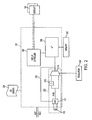
- FIG. 1 illustrates an exemplary computer system 100 that may be implemented in one embodiment.
- the components listed in FIG. 1 are merely examples of one possible implementation.
- Other components, buses, and/or protocols may be used in other implementations without departing from the spirit and scope of the detailed description.
- a computer system 100 includes a central processing unit (CPU) 102 that may be electrically coupled to a bridge logic device 106 by a CPU bus.
- the bridge logic device 106 is sometimes referred to as a "North bridge" vis-à-vis its position with respect to other systems components (such as the South bridge 119).
- the North bridge 106 may electrically couple to a main memory array 104 via a memory bus, and may further electrically couple to a GPU 108 via an advanced graphics port (AGP) bus.
- AGP advanced graphics port
- the North bridge 106 also may couple the CPU 102, the memory 104, and the GPU 108 to the other peripheral devices in the system through, for example, a primary expansion bus (BUS A) such as a PCI bus or an EISA bus.
- BUS A primary expansion bus
- Various components that operate using the bus protocol of BUS A may reside on this bus, such as an audio device 110, an IEEE 1394 interface device 112, and a network interface card (NIC) 114. These components may be integrated onto the PCB, or they may be plugged into expansion slots 118 that are connected to BUS A. If other secondary expansion buses are provided in computer system 100, another bridge logic device 119 may be used to electrically couple the primary expansion bus, BUS A, to a secondary expansion bus (not shown). As mentioned above, the bridge logic device 119 is sometimes referred to as a "South bridge" because of its position with respect to other system components.
- two or more of the components shown in FIG. 1 may be implemented as a single component.
- the GPU may be integrated along with the North bridge 106 or any other component with the computer system 100.
- the computer system 100 may couple to one or more display units 120 via the GPU 108. In this manner, the computer system 100 may support rendering computer generated graphic images to the one or more display units 120. In some embodiments, at least one of the one or more display units 120 may be integrated within the computer system 100, such as in the case of a laptop type computer system.
- the computer system 100 may be contained within an enclosure 122. Further, the enclosure 122 may have a limited thermal capacity or budget. For example, in some embodiments, the thermal budget for the enclosure 122 may be 32 watts. As mentioned previously, many electronic devices, such as computer system 100, are manufactured in increasingly smaller enclosures 122 such that the thermal budget for the device may decrease with successive product generations.
- the computer system 100 may ensure that it does not exceed its thermal budget by implementing one or more power regulation circuits 124 or schemes.
- the one or more power regulation circuits 124 may take the form of temperature monitoring devices.
- the temperature monitoring devices of in the power regulation circuit 124 may be one or more silicon based diodes (not shown), which may have temperature coefficient of approximately negative two millivolts per degree Celsius. As the temperature increases, the voltage across these diodes may decrease. Similarly, as the temperature decreases, the voltage across these diodes may increase.
- the power regulation circuit 124 may monitor this changing voltage to determine the operating temperature of the power regulation circuit 124 and/or the computer system 100.
- the GPU in these systems may have the widest variation in operating power and may be one of the largest power consumption components within the computer system 100.
- the CPU 102 may consume the greatest amount of power at 30 watts
- the GPU 108 may consume the second most amount of power ranging from 5 to 18 watts of power.
- the memory 104 may consume approximately 3 to 4 watts of power while the North bridge 106 may consume 2 to 4 watts of power.
- the GPU 108 may be one of the largest power consumption components within the computer system 100, conventional computer systems often attempt to perform thermal management functions on the GPU 108.
- the thermal management functions implemented in conventional computer systems often result in glitches in an image displayed on at least one of the one or more displays 120.
- These glitches may be because conventional thermal management circuitry often has only a few options to control the heat generated by any particular component within the computer system 100.
- one such thermal management option is to reduce the speed of the CPU 102 so that it consumes only a minimal amount of power. This may be accomplished by reducing the operational speed of the CPU, however, this action often introduces glitches in the images being rendered by the CPU because there may be insufficient processing power available to deliver, in a timely manner, the images to display motion graphics. These glitches may affect the operation of motion-based graphic items, such as playing movies on the computer system 100.
- the power regulation circuit 124 may implement thermal management functions on the computer system 100 without causing glitches in the image displayed on the one or more displays 120.
- FIG. 2 illustrates the GPU 108 with such a thermal management scheme.
- the GPU 108 may receive data via the AGP bus and process and display it to the one or more displays 120.
- the GPU 108 may receive a GPU_ENABLE signal (described in more detail below with regard to FIG. 3A ) from the power regulation circuit 124.
- a memory 202 may be coupled to the GPU 108.
- the memory 202 may be the same as the memory 104 in the computer system 100.
- the memory 202 may be a dedicated video memory such as a video random access memory (VRAM) that is separate from the memory 104.
- VRAM video random access memory
- the memory 202 may store data operated upon by the GPU 108.
- the GPU 108 may include a display controller 204, a microprocessing engine 206, and clock circuitry 208.
- the display controller 204 may render images on the one or more displays 120 by conveying picture format data to the one or more displays 120.
- the format used to convey video data between the display controller 204 and the one or more displays 120 is the digital visual interface (DVI) standard.
- the format is the video graphics array (VGA) standard. Embodiments that include DVI and/or VGA are exemplary only, in fact, other standards and/or video standards may be used in alternative embodiments.
- the microprocessing engine 206 may be coupled to the display controller 204 and may provide raw image data that is then formatted by the display controller 204 into data that can be displayed by the one or more displays 120.
- An operating system (OS) driver 209 may couple to the GPU 108 and direct the execution of applications on the GPU 108.
- the actual OS driver 209 implemented on the computer system 100 may vary.
- the OS driver 209 may be an Mac OS driver from Apple Inc.
- the OS driver may be a Windows based driver from Microsoft, Inc.
- the OS driver 209 may be any suitable OS driver from any suitable OS.
- the display controller 204 may consume a relatively constant amount of power while the microprocessing engine 206 may have power consumption that varies with the particular application being executed. In this manner, the microprocessing engine 206 may consume a majority of the power of the GPU 108 when the OS driver 209 directs it to execute a graphics intensive application. For example, the display controller 204 may account for 4 watts of relatively constant power consumption while the microprocessing engine 206 may account for 1 to 18 watts of variable power consumption. Thus if the thermal budget of the enclosure 122 is 18 watts and the display controller 204 and the microprocessing engine 206 are consuming the maximum amount of power, then the thermal budget of the enclosure has been exceeded by approximately 22%. This is but one example of why implementing thermal management of the GPU 108 may be desirable. In addition, implementing thermal management of the GPU 108 may make the overall computer system 100 more energy efficient.
- the potentially varying power consumption of components may present special challenges for consumer electronics with smaller enclosures.
- the enclosure 122 (shown in FIG. 1 ) may have a smaller thermal budget than a larger enclosure.
- smaller electronic devices often have less margin for overages in the variable amount of power consumed and/or heat generated.
- the computer system 100 is a desktop computer its enclosure 122 may have a larger thermal budget than a similarly equipped (e.g., similar processor speed, memory capacity, etc.) laptop computer and the laptop computer may not be able to tolerate power overages resulting from varying power consumption. Since these electronic devices may have smaller thermal budgets and less margin for overages in the way of power consumption, it may be desirable to control the variable power consumption that may cause such overages.
- Control for the variable power consumption may be provided, in part, by the clock circuitry 208.
- the clock circuitry 208 may include a crystal 210 that couples to an oscillation circuit 212. While the crystal 210 is shown as coupled between two terminals of the GPU 108, other embodiments may implement the crystal 210 in a single terminal arrangement, where the crystal 210 couples between a single terminal of the GPU 108 and ground.
- the oscillation circuit 212 may be any type and may further include clock trees and/or frequency modulation circuitry, such as a phase-locked loop (PLL).
- PLL phase-locked loop
- the resulting signal from the oscillation circuit 212 may be a RAW clock signal that may be coupled to the display controller 204.
- the RAW dock signal also may be coupled to the divider 214 where it is modified by a divide value and then provided to a multiplexer 216.
- the RAW clock signal may be a frequency synthesized signal from a crystal oscillator.
- the RAW clock signal may come from a PLL that synthesizes a relatively frequency stable clock signal coming from a crystal oscillator.
- Other embodiments may implement a delay-locked loop (DLL) to achieve the same functionality.
- An exemplary RAW clock frequency range includes from about 100MHz to about 1 GHz.
- the divider 214 may provide a divided down version of the RAW clock signal having a lower frequency than the RAW clock signal.
- divider values for divider 214 may include 2 to 32.
- the divider value may be set such that the timing signal of the divider may have a very low frequency, and in some cases may be close to zero.
- the divider 214 is a 3-bit divider capable of being set at values ranging from 2 to 256, then the divider 214 may be configured to have a divider value of 256, yielding a very low frequency (shown as 308 in FIG. 3E below).
- the power consumed by microprocessing engine 206 is approximately proportional to the frequency from the divider 214, and therefore, the power consumed by the microprocessing engine 206 may be controlled by controlling the divider values for divider 214.
- the power consumed by the microprocessing engine 206 may be lower than when the timing signal is not substantially zero.
- the multiplexer 216 may select between the RAW clock coming from the oscillation circuit 212 and a divided down version of the same from divider 214. The multiplexer 216 may select this based upon the GPU_ENABLE signal coming from the power regulation circuit 124.
- the GPU_ENABLE signal may be used to control the multiplexer's selection between the RAW clock coming from the oscillation circuit 212 and a divided down version of the same from divider 214, where the time period that either signal may be selected for may vary based on the pulse width of the GPU_ENABLE signal (as described below in the context of FIG. 3A ).
- the clock signal provided to the microprocessing engine 206 may be a duty-cycle weighted-average value of the two clock rates. In some embodiments, more than two signals are averaged by the multiplexer 216.
- the overall clock signal provided to the microprocessing engine 206 from the multiplexer 216 may be configured by so that the speed of execution of the microprocessing engine 206 may be proactively controlled. That is, logic blocks (not shown) within the microprocessing engine 206 may be triggered to operate off of transitions from the signal coming from the multiplexer 216.
- transition may be used to refer to a high-to-low movement of a signal and/or a low-to-high movement of a signal.
- the logic blocks consume a certain amount of power and generate a certain amount of heat with each transition. Because the average of the RAW clock and a divided down version of the same may contain fewer transitions, the amount of heat produced by the GPU 108 may be reduced.
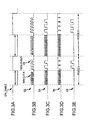
- the GPU_ENABLE signal may be in the form of a pulse width modulated (PWM) signal as shown in FIG. 3A .
- PWM pulse width modulated
- the PWM signal may be a signal with varying pulse widths as indicated by the double ended arrows in FIG. 3A . These varying pulse widths may result in one or more varying periods of GPU_ENABLE such as PERIOD A and/or PERIOD B shown in FIG. 3A .
- the widths of the PWM signal may vary based on predetermined algorithms within the power regulation circuit 124. In other embodiments, the widths of the PWM signal may vary based on input from the OS driver 209. Comparative examples may implement the GPU_ENABLE signal in the form of an analog voltage level or a register setting.
- the multiplexer 216 may selectively couple the divided down version of the RAW clock from divider 214 to the microprocessing engine 206. Similarly, when the GPU_ENABLE is low, the multiplexer 216 may selectively couple the RAW clock coming from the oscillation circuit 212 to the microprocessing engine 206.
- An exemplary resulting clock signal 302 provided to the microprocessing engine 206 is shown in FIG. 3B . Because the pulse width of GPU_ENABLE is wider in PERIOD B than PERIOD A, a greater number of transitions may occur in the clock signal 302. In this example, PERIOD A is shown to include twelve total transitions, eight from the RAW clock and 4 from the divider 214.
- PERIOD B is shown to contain eighteen total transitions, twelve from RAW clock and six from the divider 214.
- the clock signal 302 may have a higher average frequency during PERIOD B than PERIOD A and the GPU 108 may operate at a greater temperature during PERIOD B than during PERIOD A.
- the clock signal provided to the GPU 108 may be modified in other ways.
- the average number of transitions that occur in the signal provided by the multiplexer 216 may be kept relatively constant and the pulse width of the GPU_ENABLE signal may be kept relatively constant, yet the overall distribution of those transitions may be varied.
- FIG. 3C represents an exemplary signal 304 with these characteristics.
- the frequency of the RAW clock e.g., by adjusting the PLL output
- changing frequency of the signal from the divider 214 e.g., by adjusting the divider value
- different transition profiles may be achieved. Comparing the signal 302 to the signal 304, they have the same number of transitions during PERIOD A and PERIOD B respectively, and therefore the GPU 108 may execute approximately the same number of operations during PERIOD A and PERIOD B respectively.
- the overall number of transitions during any given period of the signals 302-308 may be the same, the distribution of the transitions may vary.
- the signal 304 may contain more transitions from the RAW clock and fewer from the divider 214.
- the GPU 108 may execute more instructions in the RAW clock portion of PERIOD A when the signal 304 is provided to the GPU 108 than if the signal 302 is provided to the GPU 108.
- the amount of heat generated by the GPU 108 versus time for the signals 302-308 may be different even though the same number of operations may be executed by the GPU 108. This feature may be desirable if the packaging of the GPU 108 changes (for example, because of a cost decision at some later point during manufacturing), and as a result, the ability of the GPU 108 to dissipate heat changes.
- alternative transition profiles also may be achieved by elongating portions of the RAW clock provided to the microprocessing engine 206.
- FIG. 3D illustrates an exemplary timing signal 306 with such a transition profile.
- the alternative profiles also may be achieved by programming the divider 214 to a divider value that results in the RAW clock having a frequency of substantially zero.
- FIG. 3E illustrates an exemplary timing signal 308 where the RAW clock has a frequency of substantially zero for at least a portion of the signal period.
- variable power consumption requirements of the microprocessing engine 206 may be more finely controlled by modifying the rate of execution of applications being executed on the microprocessing engine 206 independent of the operation of the display controller 204. If the signals 302-308 were applied to the display controller 204, this may result in glitches on the one or more displays 120.
- the signals 302-308 may be applied to the microprocessing engine 206 while the microprocessing engine 206 may be executing commands from the OS driver 209, this may result in fewer glitches in the images displayed on the one or more displays 120.
- the OS driver 209 may need to wait for the microprocessing engine 206 to be finished with any particular set of instructions before it can implement thermal management mechanisms.
- the OS driver 209 may have to fit clock modifications within processing breaks of the microprocessing engine 206.
- the microprocessing engine 206 may continue to increase in temperature even though the power regulation circuit 124 may indicate that thermal management needs to be implemented.
- the power regulation circuit 124 is able to implement some form of thermal management (i.e., at the next break in processing)
- the GPU 108 may already be consuming so much power such that drastic measures may need to be taken, such as shutting down the GPU 108 completely. For example, if the GPU 108 is consuming too much power and thermal management cannot be implemented by the OS driver 209, then the computer system 100 may simply power the GPU 108 down to prevent catastrophic damage.
- Powering down the GPU 108 in this manner may result in glitches in the image rendered on the one or more displays 120.
- these glitches may be prevented from occurring because the microprocessing engine 206 may have its power actively (as opposed to passively) controlled so that the number of times the GPU 108 is catastrophically shut down is minimized.
- Implementing this thermal management scheme may be particularly desirable in portable systems (where the thermal budget is relatively small), which support multiple displays and may require additional processing by the microprocessing engine 206 (and therefore generate additional heat).
- thermal viruses may be maliciously implemented. These thermal viruses deliberately contain no processing breaks in the code such that the computer system will be powered down from thermal overload. By implementing the signal 302 the effects of these thermal viruses may be overcome because the power regulation circuit 124 may control the heat generated regardless of the OS driver 209 having to wait for processing breaks.
- the oscillation circuit 212 may de-skew one or more of the timing signals at various points along the timing path. For example, the signal coming from the divider 214 to the multiplexer 216 may be routed across the GPU 108, thereby introducing clock skew. In these situations, the oscillation circuit 212 may utilize a PLL to remove this skew by comparing the signal in question to the signal generated by the oscillation circuit 212, for example through connection 218. It should be noted that connection 218 is but one representation of circuitry capable of providing timing signals to the microprocessing engine 206 and other, more complicated circuitry, is also possible.
Landscapes
- Engineering & Computer Science (AREA)
- Theoretical Computer Science (AREA)
- Physics & Mathematics (AREA)
- General Physics & Mathematics (AREA)
- General Engineering & Computer Science (AREA)
- Computer Hardware Design (AREA)
- Human Computer Interaction (AREA)
- Multimedia (AREA)
- Control Of Indicators Other Than Cathode Ray Tubes (AREA)
- Power Sources (AREA)
- Multi Processors (AREA)
Claims (14)
- Eine Grafikverarbeitungseinheit (Graphics Processing Unit, GPU), aufweisend:eine Anzeigesteuerung;eine Mikroprozessorengine, die mit der Anzeigesteuerung gekoppelt ist;eine Taktschaltung, die mit der Anzeigesteuerung und der Mikroprozessorengine gekoppelt ist, wobei die Taktschaltung weiterhin aufweist:ein Rohtaktsignal, welches mit der Anzeigesteuerung gekoppelt ist;einen Teiler, der mit dem Rohtaktsignal gekoppelt ist, wobei der Teiler angeordnet ist, um eine geteilte Version des Rohtaktsignals zu erzeugen;einen Multiplexer, der mit dem Teiler und dem Rohtaktsignal gekoppelt ist, wobei der Multiplexer angeordnet ist, um wahlweise das Rohtaktsignal oder die geteilte Version des Rohtaktsignals für die Mikroprozessorengine als ein Timingsignal zur Verfügung zu stellen, und wobei weiterhin der Multiplexer angeordnet ist, um wahlweise das Rohtaktsignal oderdie geteilte Version des Rohrtaktsignals für die Mikroprozessorengine gemäß einem Steuersignal (GPU_ENABLE) zur Verfügung zu stellen;dadurch gekennzeichnet, dass:das Steuersignal (GPU_ENABLE) ein pulsbreitenmoduliertes Signal mit Breiten ist, die gesteuert werden durch entweder eine Leistungsregelschaltung (124) oder durch einen Betriebssystemtreiber, der mit der GPU gekoppelt ist.
- GPU nach Anspruch 1, bei welcher der Teiler so eingestellt ist, dass die geteilte Version des Rohtaktsignals eine Frequenz von im Wesentlichen Null aufweist.
- GPU nach Anspruch 1, bei welcher die Mikroprozessorengine angeordnet ist, um Operationen bei einer verringerten Ausführungsrate auszuführen, während die Anzeigesteuerung bei derselben Ausführungsrate arbeitet.
- GPU nach Anspruch 1, bei welcher das Timingsignal, welches der Mikroprozessorengine zur Verfügung gestellt wird, einen Durchschnitt des Rohtaktsignals und der geteilten Version des Rohtaktsignals darstellt.
- GPU nach Anspruch 3, weiterhin zumindest ein zusätzliches Taktsignal aufweisend, welches dem Multiplexer zur Verfügung gestellt wird, wobei das Timingsignal, welches der Mikroprozessorengine zur Verfügung gestellt wird, einen Durchschnitt des Rohtaktsignals, der geteilten Version des Rohtaktsignals und des zumindest einen zusätzlichen Taktsignals darstellt.
- GPU nach Anspruch 4, bei welcher der Durchschnittswert, der durch das Timingsignal dargestellt wird, unter Verwendung des Steuersignals modifiziert wird, welches dem Multiplexer zur Verfügung gestellt wird.
- GPU nach Anspruch 6, bei welcher das Steuersignal auf einer Messung einer Temperaturveränderung der GPU basiert.
- GPU nach Anspruch 7, bei welcher das Steuersignal auf Temperaturveränderungen einer Flächendiode basiert.
- GPU nach Anspruch 1, bei welcher das Timingsignal eine größere Anzahl von Übergängen von dem Rohtaktsignal umfasst als die Anzahl von Übergängen von der heruntergeteilten Version des Rohtaktsignals.
- GPU nach Anspruch 9, bei welcher das Verhältnis zwischen den Übergängen von dem Rohtaktsignal verglichen mit den Übergängen von der geteilten Version des Rohtaktsignals modifiziert wird, während die GPU Instruktionen ausführt.
- GPU nach Anspruch 10, bei welcher die Gesamtanzahl von Übergängen in dem Timingsignal im Wesentlichen konstant ist, obwohl das Verhältnis zwischen der Anzahl von Übergängen von dem Rohtaktsignal und der Anzahl von Übergängen von der geteilten Version des Rohtaktsignals modifiziert wird.
- GPU nach Anspruch 1, bei welcher das Timingsignal zu der Taktschaltung zurückgegeben wird, um das Timingsignal zu entzerren.
- GPU nach Anspruch 1, bei welcher das Timingsignal unabhängig von Breaks in einem Code modifiziert wird, welcher durch die Mikroprozessorengine ausgeführt wird.
- GPU nach Anspruch 1, bei welcher das Übergangsprofil des Timingsignals modifiziert wird, während die Gesamtanzahl der Operationen beibehalten wird, die durch die Mikroprozessorengine ausgeführt werden.
Applications Claiming Priority (3)
| Application Number | Priority Date | Filing Date | Title |
|---|---|---|---|
| US5351908P | 2008-05-15 | 2008-05-15 | |
| US12/212,805 US8525840B2 (en) | 2008-05-15 | 2008-09-18 | Thermal management of graphics processing units |
| PCT/US2009/041446 WO2009140037A2 (en) | 2008-05-15 | 2009-04-22 | Thermal management of graphics processing units |
Publications (2)
| Publication Number | Publication Date |
|---|---|
| EP2294572A2 EP2294572A2 (de) | 2011-03-16 |
| EP2294572B1 true EP2294572B1 (de) | 2013-06-05 |
Family
ID=41315732
Family Applications (1)
| Application Number | Title | Priority Date | Filing Date |
|---|---|---|---|
| EP09747123.9A Not-in-force EP2294572B1 (de) | 2008-05-15 | 2009-04-22 | Thermisches management von grafikverarbeitungseinheiten |
Country Status (4)
| Country | Link |
|---|---|
| US (1) | US8525840B2 (de) |
| EP (1) | EP2294572B1 (de) |
| CN (1) | CN102077271B (de) |
| WO (1) | WO2009140037A2 (de) |
Families Citing this family (16)
| Publication number | Priority date | Publication date | Assignee | Title |
|---|---|---|---|---|
| US7433191B2 (en) * | 2005-09-30 | 2008-10-07 | Apple Inc. | Thermal contact arrangement |
| US9063713B2 (en) | 2008-10-28 | 2015-06-23 | Apple Inc. | Graphics controllers with increased thermal management granularity |
| US8924752B1 (en) | 2011-04-20 | 2014-12-30 | Apple Inc. | Power management for a graphics processing unit or other circuit |
| US8477490B2 (en) | 2011-05-02 | 2013-07-02 | Apple Inc. | Cooling system for mobile electronic devices |
| CN103106637A (zh) * | 2011-11-11 | 2013-05-15 | 辉达公司 | 标准gpu模块、包含模块的系统和用于驱动系统的方法 |
| US8856566B1 (en) | 2011-12-15 | 2014-10-07 | Apple Inc. | Power management scheme that accumulates additional off time for device when no work is available and permits additional power consumption by device when awakened |
| US9390461B1 (en) | 2012-05-08 | 2016-07-12 | Apple Inc. | Graphics hardware mode controls |
| US9035956B1 (en) | 2012-05-08 | 2015-05-19 | Apple Inc. | Graphics power control with efficient power usage during stop |
| US9250665B2 (en) | 2012-06-07 | 2016-02-02 | Apple Inc. | GPU with dynamic performance adjustment |
| EP2701309A1 (de) * | 2012-08-21 | 2014-02-26 | Alcatel Lucent | System zur Herstellung eines Systems zur Erkennung des Systemtakts und des Temperaturgradienten |
| US9125299B2 (en) | 2012-12-06 | 2015-09-01 | Apple Inc. | Cooling for electronic components |
| US9223167B2 (en) | 2013-06-26 | 2015-12-29 | Apple Inc. | Liquid crystal switching barrier thermal control |
| US9389029B2 (en) | 2013-09-30 | 2016-07-12 | Apple Inc. | Heat transfer structure |
| US9674986B2 (en) | 2015-08-03 | 2017-06-06 | Apple Inc. | Parallel heat spreader |
| US11895588B2 (en) | 2020-08-05 | 2024-02-06 | Analog Devices, Inc. | Timing precision maintenance with reduced power during system sleep |
| US20230224387A1 (en) | 2022-01-10 | 2023-07-13 | Apple Inc. | Handheld electronic device |
Family Cites Families (56)
| Publication number | Priority date | Publication date | Assignee | Title |
|---|---|---|---|---|
| US4104523A (en) | 1976-10-06 | 1978-08-01 | Martin Marietta Corporation | Electronic alpha particle counter |
| US4620248A (en) | 1984-09-04 | 1986-10-28 | Magnetic Peripherals Inc. | Apparatus for controlling humidity in a disk drive |
| US4614528A (en) | 1985-06-24 | 1986-09-30 | System Development Corp. | Dry air breather assembly |
| US4863499A (en) | 1988-07-29 | 1989-09-05 | Donaldson Company, Inc. | Anti-duffusion chemical breather assembly for disk drives |
| US4982783A (en) | 1988-11-22 | 1991-01-08 | Varian Associates, Inc. | Self-tightening heat sink |
| US5025336A (en) | 1989-11-06 | 1991-06-18 | Prairietek Corporation | Disk drive apparatus |
| US5148337A (en) | 1990-09-20 | 1992-09-15 | Multiform Desiccants, Inc. | Controlled rate adsorbent and disc drive stabilizing unit |
| US5392177A (en) | 1991-10-04 | 1995-02-21 | International Business Machines Corporation | Sealed DASD having humidity control and method of making same |
| US5440172A (en) | 1993-06-28 | 1995-08-08 | Sundstrand Corporation | Integral heat sink interface |
| JP3075957B2 (ja) | 1995-05-30 | 2000-08-14 | 株式会社東芝 | コンピュータシステム |
| US5822596A (en) * | 1995-11-06 | 1998-10-13 | International Business Machines Corporation | Controlling power up using clock gating |
| US5745344A (en) | 1995-11-06 | 1998-04-28 | International Business Machines Corporation | Heat dissipation apparatus and method for attaching a heat dissipation apparatus to an electronic device |
| JPH09305569A (ja) * | 1996-01-17 | 1997-11-28 | Texas Instr Inc <Ti> | Cpuの動作特性に応じてコンピュータの動作を制御する方法と装置 |
| US5781768A (en) | 1996-03-29 | 1998-07-14 | Chips And Technologies, Inc. | Graphics controller utilizing a variable frequency clock |
| US6286212B1 (en) | 1996-05-29 | 2001-09-11 | Manford L. Eaton | Thermally conductive material and method of using the same |
| US6143058A (en) | 1997-03-17 | 2000-11-07 | Donaldson Company, Inc. | Adsorbent construction and method |
| JPH10268963A (ja) | 1997-03-28 | 1998-10-09 | Mitsubishi Electric Corp | 情報処理装置 |
| US6400361B2 (en) * | 1998-04-23 | 2002-06-04 | United Technologies Dearborn, Inc | Graphics processor architecture employing variable refresh rates |
| TW406219B (en) * | 1998-08-26 | 2000-09-21 | Via Tech Inc | PLL clock generation circuit that is capable of programming frequency and skew |
| US6624816B1 (en) | 1999-09-10 | 2003-09-23 | Intel Corporation | Method and apparatus for scalable image processing |
| US6407595B1 (en) * | 2000-04-04 | 2002-06-18 | Silicon Integrated Systems Corp. | Digital clock throttling means |
| US6504243B1 (en) | 2000-04-07 | 2003-01-07 | Advanced Micro Devices, Inc. | Removable heat transfer apparatus for a pin grid array (PGA) device, and associated installation and removal methods |
| US6462410B1 (en) | 2000-08-17 | 2002-10-08 | Sun Microsystems Inc | Integrated circuit component temperature gradient reducer |
| US7190585B2 (en) | 2000-09-29 | 2007-03-13 | Intel Corporation | Thermal heat spreaders designed for lower cost manufacturability, lower mass and increased thermal performance |
| CN1151416C (zh) * | 2000-12-18 | 2004-05-26 | 联想(北京)有限公司 | 根据cpu的利用率调节cpu频率的方法 |
| US6555486B2 (en) | 2001-07-12 | 2003-04-29 | Cool Shield, Inc. | Thermally conductive silk-screenable interface material |
| US6886625B1 (en) | 2001-08-23 | 2005-05-03 | Cool Options, Inc. | Elastomeric heat sink with a pressure sensitive adhesive backing |
| US6896045B2 (en) | 2001-10-24 | 2005-05-24 | Cool Shield, Inc. | Structure and method of attaching a heat transfer part having a compressible interface |
| JP2003173173A (ja) * | 2001-12-07 | 2003-06-20 | Rohm Co Ltd | 液晶ドライバ装置 |
| US6618249B2 (en) | 2002-02-05 | 2003-09-09 | Quantum Corporation | Thermal cooling system for densely packed storage devices |
| US6832410B2 (en) | 2002-04-23 | 2004-12-21 | Hewlett-Packard Development Company, L.P. | High performance cooling device with side mount fan |
| US7149909B2 (en) | 2002-05-09 | 2006-12-12 | Intel Corporation | Power management for an integrated graphics device |
| US6891724B2 (en) | 2002-06-12 | 2005-05-10 | Intel Corporation | Increasing thermal conductivity of thermal interface using carbon nanotubes and CVD |
| JP3885670B2 (ja) | 2002-06-19 | 2007-02-21 | 松下電器産業株式会社 | 半導体装置 |
| US7882369B1 (en) * | 2002-11-14 | 2011-02-01 | Nvidia Corporation | Processor performance adjustment system and method |
| JP4526771B2 (ja) | 2003-03-14 | 2010-08-18 | 株式会社半導体エネルギー研究所 | 半導体装置の作製方法 |
| US6987671B2 (en) | 2003-06-26 | 2006-01-17 | Intel Corporation | Composite thermal interface devices and methods for integrated circuit heat transfer |
| US7451332B2 (en) * | 2003-08-15 | 2008-11-11 | Apple Inc. | Methods and apparatuses for controlling the temperature of a data processing system |
| US20050077614A1 (en) | 2003-10-10 | 2005-04-14 | Chengalva Suresh K. | Semiconductor device heat sink package and method |
| US7125433B2 (en) | 2003-12-31 | 2006-10-24 | Donaldson Company, Inc. | Dual diffusion channel filter |
| US7006353B2 (en) | 2004-03-11 | 2006-02-28 | International Business Machines Corporation | Apparatus and method for attaching a heat sink to an integrated circuit module |
| DE602004023277D1 (de) * | 2004-04-22 | 2009-11-05 | Sony Ericsson Mobile Comm Ab | Kühlsystem für mobiles Endgerät zur drahtlosen Kommunikation |
| CN100462896C (zh) * | 2004-05-19 | 2009-02-18 | 鸿富锦精密工业(深圳)有限公司 | Cpu工作电压调整系统 |
| US7085135B2 (en) | 2004-06-21 | 2006-08-01 | International Business Machines Corporation | Thermal dissipation structure and method employing segmented heat sink surface coupling to an electronic component |
| US7454316B2 (en) * | 2004-10-08 | 2008-11-18 | International Business Machines Corporation | Method and apparatus for monitoring and enhancing on-chip microprocessor reliability |
| US20060120051A1 (en) | 2004-12-03 | 2006-06-08 | Chris Macris | Liquid metal thermal interface material system |
| US7045885B1 (en) | 2004-12-09 | 2006-05-16 | Hewlett-Packard Development Company, L.P. | Placement of absorbing material in a semiconductor device |
| US7269015B2 (en) | 2005-02-01 | 2007-09-11 | Tyco Electronics Corporation | Heat sink interface insert |
| US7730336B2 (en) | 2006-05-30 | 2010-06-01 | Ati Technologies Ulc | Device having multiple graphics subsystems and reduced power consumption mode, software and methods |
| US7401243B2 (en) * | 2005-06-21 | 2008-07-15 | Dell Products L.P. | Demand-based dynamic clock control for transaction processors |
| US7433191B2 (en) | 2005-09-30 | 2008-10-07 | Apple Inc. | Thermal contact arrangement |
| EP1785982A1 (de) * | 2005-11-14 | 2007-05-16 | Texas Instruments Incorporated | Leistungsverwaltung einer Anzeige |
| US7750912B2 (en) * | 2005-11-23 | 2010-07-06 | Advanced Micro Devices, Inc. | Integrating display controller into low power processor |
| US7440281B2 (en) | 2006-02-01 | 2008-10-21 | Apple Inc. | Thermal interface apparatus |
| TW200803409A (en) * | 2006-06-23 | 2008-01-01 | Delta Electronics Inc | Fan with vibration reminding function |
| US9063713B2 (en) | 2008-10-28 | 2015-06-23 | Apple Inc. | Graphics controllers with increased thermal management granularity |
-
2008
- 2008-09-18 US US12/212,805 patent/US8525840B2/en active Active
-
2009
- 2009-04-22 WO PCT/US2009/041446 patent/WO2009140037A2/en not_active Ceased
- 2009-04-22 EP EP09747123.9A patent/EP2294572B1/de not_active Not-in-force
- 2009-04-22 CN CN200980125004.XA patent/CN102077271B/zh not_active Expired - Fee Related
Also Published As
| Publication number | Publication date |
|---|---|
| US8525840B2 (en) | 2013-09-03 |
| HK1155270A1 (en) | 2012-05-11 |
| EP2294572A2 (de) | 2011-03-16 |
| WO2009140037A2 (en) | 2009-11-19 |
| CN102077271B (zh) | 2013-09-25 |
| US20090284534A1 (en) | 2009-11-19 |
| WO2009140037A3 (en) | 2010-04-08 |
| CN102077271A (zh) | 2011-05-25 |
Similar Documents
| Publication | Publication Date | Title |
|---|---|---|
| EP2294572B1 (de) | Thermisches management von grafikverarbeitungseinheiten | |
| EP1723491B1 (de) | Dynamische taktsteuerschaltung und verfahren | |
| EP2278432B1 (de) | System und Verfahren zur adaptiven temperaturabhängigen Rückkopplungssteuerung einer Taktversorgung | |
| US7149909B2 (en) | Power management for an integrated graphics device | |
| EP0706108A2 (de) | Taktsteuerungsschaltungen für Mikroprozessoren | |
| US8127156B2 (en) | Systems and methods for control of integrated circuits comprising body biasing systems | |
| US20040017234A1 (en) | VCC adaptive dynamically variable frequency clock system for high performance low power microprocessors | |
| US9772670B2 (en) | Power-control devices | |
| EP0613075B1 (de) | Mikroprozessor mit verteilten Taktgebern | |
| US9195260B2 (en) | Semiconductor device, radio communication terminal using same, and clock frequency control method | |
| US20230198528A1 (en) | Droop detection and control of digital frequency-locked loop | |
| EP3930137B1 (de) | Leistungsverhandlungssequenz zur verbesserung der benutzererfahrung und der batterielebensdauer | |
| US7093140B2 (en) | Method and apparatus for configuring a voltage regulator based on current information | |
| US9996138B2 (en) | Electronic system and related clock managing method | |
| HK1155270B (en) | Thermal management of graphics processing units | |
| US8402288B2 (en) | Apparatus and method for controlling voltage and frequency using multiple reference circuits | |
| CN113504826B (zh) | 动态电压频率调整电路以及动态电压频率调整方法 | |
| US7813410B1 (en) | Initiating spread spectrum modulation | |
| WO2023075750A1 (en) | Temperature settings for temperature control circuits | |
| JP2009238119A (ja) | メインボード用電力管理方法及びシステム | |
| US20180074544A1 (en) | Control circuit of power gating and semiconductor device |
Legal Events
| Date | Code | Title | Description |
|---|---|---|---|
| PUAI | Public reference made under article 153(3) epc to a published international application that has entered the european phase |
Free format text: ORIGINAL CODE: 0009012 |
|
| 17P | Request for examination filed |
Effective date: 20101124 |
|
| AK | Designated contracting states |
Kind code of ref document: A2 Designated state(s): AT BE BG CH CY CZ DE DK EE ES FI FR GB GR HR HU IE IS IT LI LT LU LV MC MK MT NL NO PL PT RO SE SI SK TR |
|
| AX | Request for extension of the european patent |
Extension state: AL BA RS |
|
| DAX | Request for extension of the european patent (deleted) | ||
| REG | Reference to a national code |
Ref country code: HK Ref legal event code: DE Ref document number: 1155270 Country of ref document: HK |
|
| GRAP | Despatch of communication of intention to grant a patent |
Free format text: ORIGINAL CODE: EPIDOSNIGR1 |
|
| GRAS | Grant fee paid |
Free format text: ORIGINAL CODE: EPIDOSNIGR3 |
|
| GRAA | (expected) grant |
Free format text: ORIGINAL CODE: 0009210 |
|
| AK | Designated contracting states |
Kind code of ref document: B1 Designated state(s): AT BE BG CH CY CZ DE DK EE ES FI FR GB GR HR HU IE IS IT LI LT LU LV MC MK MT NL NO PL PT RO SE SI SK TR |
|
| REG | Reference to a national code |
Ref country code: GB Ref legal event code: FG4D |
|
| REG | Reference to a national code |
Ref country code: CH Ref legal event code: EP |
|
| REG | Reference to a national code |
Ref country code: AT Ref legal event code: REF Ref document number: 616062 Country of ref document: AT Kind code of ref document: T Effective date: 20130615 |
|
| REG | Reference to a national code |
Ref country code: IE Ref legal event code: FG4D |
|
| REG | Reference to a national code |
Ref country code: DE Ref legal event code: R096 Ref document number: 602009016264 Country of ref document: DE Effective date: 20130801 |
|
| REG | Reference to a national code |
Ref country code: HK Ref legal event code: GR Ref document number: 1155270 Country of ref document: HK |
|
| REG | Reference to a national code |
Ref country code: AT Ref legal event code: MK05 Ref document number: 616062 Country of ref document: AT Kind code of ref document: T Effective date: 20130605 |
|
| PG25 | Lapsed in a contracting state [announced via postgrant information from national office to epo] |
Ref country code: LT Free format text: LAPSE BECAUSE OF FAILURE TO SUBMIT A TRANSLATION OF THE DESCRIPTION OR TO PAY THE FEE WITHIN THE PRESCRIBED TIME-LIMIT Effective date: 20130605 Ref country code: ES Free format text: LAPSE BECAUSE OF FAILURE TO SUBMIT A TRANSLATION OF THE DESCRIPTION OR TO PAY THE FEE WITHIN THE PRESCRIBED TIME-LIMIT Effective date: 20130916 Ref country code: AT Free format text: LAPSE BECAUSE OF FAILURE TO SUBMIT A TRANSLATION OF THE DESCRIPTION OR TO PAY THE FEE WITHIN THE PRESCRIBED TIME-LIMIT Effective date: 20130605 Ref country code: SI Free format text: LAPSE BECAUSE OF FAILURE TO SUBMIT A TRANSLATION OF THE DESCRIPTION OR TO PAY THE FEE WITHIN THE PRESCRIBED TIME-LIMIT Effective date: 20130605 Ref country code: FI Free format text: LAPSE BECAUSE OF FAILURE TO SUBMIT A TRANSLATION OF THE DESCRIPTION OR TO PAY THE FEE WITHIN THE PRESCRIBED TIME-LIMIT Effective date: 20130605 Ref country code: SE Free format text: LAPSE BECAUSE OF FAILURE TO SUBMIT A TRANSLATION OF THE DESCRIPTION OR TO PAY THE FEE WITHIN THE PRESCRIBED TIME-LIMIT Effective date: 20130605 Ref country code: GR Free format text: LAPSE BECAUSE OF FAILURE TO SUBMIT A TRANSLATION OF THE DESCRIPTION OR TO PAY THE FEE WITHIN THE PRESCRIBED TIME-LIMIT Effective date: 20130906 Ref country code: NO Free format text: LAPSE BECAUSE OF FAILURE TO SUBMIT A TRANSLATION OF THE DESCRIPTION OR TO PAY THE FEE WITHIN THE PRESCRIBED TIME-LIMIT Effective date: 20130905 |
|
| REG | Reference to a national code |
Ref country code: NL Ref legal event code: VDEP Effective date: 20130605 |
|
| REG | Reference to a national code |
Ref country code: LT Ref legal event code: MG4D |
|
| PG25 | Lapsed in a contracting state [announced via postgrant information from national office to epo] |
Ref country code: PL Free format text: LAPSE BECAUSE OF FAILURE TO SUBMIT A TRANSLATION OF THE DESCRIPTION OR TO PAY THE FEE WITHIN THE PRESCRIBED TIME-LIMIT Effective date: 20130605 Ref country code: HR Free format text: LAPSE BECAUSE OF FAILURE TO SUBMIT A TRANSLATION OF THE DESCRIPTION OR TO PAY THE FEE WITHIN THE PRESCRIBED TIME-LIMIT Effective date: 20130605 Ref country code: BG Free format text: LAPSE BECAUSE OF FAILURE TO SUBMIT A TRANSLATION OF THE DESCRIPTION OR TO PAY THE FEE WITHIN THE PRESCRIBED TIME-LIMIT Effective date: 20130905 |
|
| PG25 | Lapsed in a contracting state [announced via postgrant information from national office to epo] |
Ref country code: LV Free format text: LAPSE BECAUSE OF FAILURE TO SUBMIT A TRANSLATION OF THE DESCRIPTION OR TO PAY THE FEE WITHIN THE PRESCRIBED TIME-LIMIT Effective date: 20130605 |
|
| PG25 | Lapsed in a contracting state [announced via postgrant information from national office to epo] |
Ref country code: CZ Free format text: LAPSE BECAUSE OF FAILURE TO SUBMIT A TRANSLATION OF THE DESCRIPTION OR TO PAY THE FEE WITHIN THE PRESCRIBED TIME-LIMIT Effective date: 20130605 Ref country code: IS Free format text: LAPSE BECAUSE OF FAILURE TO SUBMIT A TRANSLATION OF THE DESCRIPTION OR TO PAY THE FEE WITHIN THE PRESCRIBED TIME-LIMIT Effective date: 20131005 Ref country code: EE Free format text: LAPSE BECAUSE OF FAILURE TO SUBMIT A TRANSLATION OF THE DESCRIPTION OR TO PAY THE FEE WITHIN THE PRESCRIBED TIME-LIMIT Effective date: 20130605 Ref country code: BE Free format text: LAPSE BECAUSE OF FAILURE TO SUBMIT A TRANSLATION OF THE DESCRIPTION OR TO PAY THE FEE WITHIN THE PRESCRIBED TIME-LIMIT Effective date: 20130605 Ref country code: PT Free format text: LAPSE BECAUSE OF FAILURE TO SUBMIT A TRANSLATION OF THE DESCRIPTION OR TO PAY THE FEE WITHIN THE PRESCRIBED TIME-LIMIT Effective date: 20131007 Ref country code: SK Free format text: LAPSE BECAUSE OF FAILURE TO SUBMIT A TRANSLATION OF THE DESCRIPTION OR TO PAY THE FEE WITHIN THE PRESCRIBED TIME-LIMIT Effective date: 20130605 |
|
| PG25 | Lapsed in a contracting state [announced via postgrant information from national office to epo] |
Ref country code: NL Free format text: LAPSE BECAUSE OF FAILURE TO SUBMIT A TRANSLATION OF THE DESCRIPTION OR TO PAY THE FEE WITHIN THE PRESCRIBED TIME-LIMIT Effective date: 20130605 Ref country code: RO Free format text: LAPSE BECAUSE OF FAILURE TO SUBMIT A TRANSLATION OF THE DESCRIPTION OR TO PAY THE FEE WITHIN THE PRESCRIBED TIME-LIMIT Effective date: 20130605 |
|
| PLBE | No opposition filed within time limit |
Free format text: ORIGINAL CODE: 0009261 |
|
| STAA | Information on the status of an ep patent application or granted ep patent |
Free format text: STATUS: NO OPPOSITION FILED WITHIN TIME LIMIT |
|
| PG25 | Lapsed in a contracting state [announced via postgrant information from national office to epo] |
Ref country code: DK Free format text: LAPSE BECAUSE OF FAILURE TO SUBMIT A TRANSLATION OF THE DESCRIPTION OR TO PAY THE FEE WITHIN THE PRESCRIBED TIME-LIMIT Effective date: 20130605 |
|
| 26N | No opposition filed |
Effective date: 20140306 |
|
| PG25 | Lapsed in a contracting state [announced via postgrant information from national office to epo] |
Ref country code: IT Free format text: LAPSE BECAUSE OF FAILURE TO SUBMIT A TRANSLATION OF THE DESCRIPTION OR TO PAY THE FEE WITHIN THE PRESCRIBED TIME-LIMIT Effective date: 20130605 |
|
| REG | Reference to a national code |
Ref country code: DE Ref legal event code: R097 Ref document number: 602009016264 Country of ref document: DE Effective date: 20140306 |
|
| PG25 | Lapsed in a contracting state [announced via postgrant information from national office to epo] |
Ref country code: MC Free format text: LAPSE BECAUSE OF FAILURE TO SUBMIT A TRANSLATION OF THE DESCRIPTION OR TO PAY THE FEE WITHIN THE PRESCRIBED TIME-LIMIT Effective date: 20130605 Ref country code: LU Free format text: LAPSE BECAUSE OF FAILURE TO SUBMIT A TRANSLATION OF THE DESCRIPTION OR TO PAY THE FEE WITHIN THE PRESCRIBED TIME-LIMIT Effective date: 20140422 |
|
| REG | Reference to a national code |
Ref country code: CH Ref legal event code: PL |
|
| REG | Reference to a national code |
Ref country code: IE Ref legal event code: MM4A |
|
| PG25 | Lapsed in a contracting state [announced via postgrant information from national office to epo] |
Ref country code: CH Free format text: LAPSE BECAUSE OF NON-PAYMENT OF DUE FEES Effective date: 20140430 Ref country code: LI Free format text: LAPSE BECAUSE OF NON-PAYMENT OF DUE FEES Effective date: 20140430 |
|
| PG25 | Lapsed in a contracting state [announced via postgrant information from national office to epo] |
Ref country code: IE Free format text: LAPSE BECAUSE OF NON-PAYMENT OF DUE FEES Effective date: 20140422 |
|
| REG | Reference to a national code |
Ref country code: FR Ref legal event code: PLFP Year of fee payment: 8 |
|
| PG25 | Lapsed in a contracting state [announced via postgrant information from national office to epo] |
Ref country code: MT Free format text: LAPSE BECAUSE OF FAILURE TO SUBMIT A TRANSLATION OF THE DESCRIPTION OR TO PAY THE FEE WITHIN THE PRESCRIBED TIME-LIMIT Effective date: 20130605 |
|
| PG25 | Lapsed in a contracting state [announced via postgrant information from national office to epo] |
Ref country code: CY Free format text: LAPSE BECAUSE OF FAILURE TO SUBMIT A TRANSLATION OF THE DESCRIPTION OR TO PAY THE FEE WITHIN THE PRESCRIBED TIME-LIMIT Effective date: 20130605 |
|
| PG25 | Lapsed in a contracting state [announced via postgrant information from national office to epo] |
Ref country code: HU Free format text: LAPSE BECAUSE OF FAILURE TO SUBMIT A TRANSLATION OF THE DESCRIPTION OR TO PAY THE FEE WITHIN THE PRESCRIBED TIME-LIMIT; INVALID AB INITIO Effective date: 20090422 Ref country code: TR Free format text: LAPSE BECAUSE OF FAILURE TO SUBMIT A TRANSLATION OF THE DESCRIPTION OR TO PAY THE FEE WITHIN THE PRESCRIBED TIME-LIMIT Effective date: 20130605 |
|
| REG | Reference to a national code |
Ref country code: FR Ref legal event code: PLFP Year of fee payment: 9 |
|
| REG | Reference to a national code |
Ref country code: FR Ref legal event code: PLFP Year of fee payment: 10 |
|
| PG25 | Lapsed in a contracting state [announced via postgrant information from national office to epo] |
Ref country code: MK Free format text: LAPSE BECAUSE OF FAILURE TO SUBMIT A TRANSLATION OF THE DESCRIPTION OR TO PAY THE FEE WITHIN THE PRESCRIBED TIME-LIMIT Effective date: 20130605 |
|
| PGFP | Annual fee paid to national office [announced via postgrant information from national office to epo] |
Ref country code: FR Payment date: 20230309 Year of fee payment: 15 |
|
| PGFP | Annual fee paid to national office [announced via postgrant information from national office to epo] |
Ref country code: GB Payment date: 20230302 Year of fee payment: 15 |
|
| PGFP | Annual fee paid to national office [announced via postgrant information from national office to epo] |
Ref country code: DE Payment date: 20230307 Year of fee payment: 15 |
|
| REG | Reference to a national code |
Ref country code: DE Ref legal event code: R119 Ref document number: 602009016264 Country of ref document: DE |
|
| GBPC | Gb: european patent ceased through non-payment of renewal fee |
Effective date: 20240422 |
|
| PG25 | Lapsed in a contracting state [announced via postgrant information from national office to epo] |
Ref country code: DE Free format text: LAPSE BECAUSE OF NON-PAYMENT OF DUE FEES Effective date: 20241105 |
|
| PG25 | Lapsed in a contracting state [announced via postgrant information from national office to epo] |
Ref country code: GB Free format text: LAPSE BECAUSE OF NON-PAYMENT OF DUE FEES Effective date: 20240422 |
|
| PG25 | Lapsed in a contracting state [announced via postgrant information from national office to epo] |
Ref country code: FR Free format text: LAPSE BECAUSE OF NON-PAYMENT OF DUE FEES Effective date: 20240430 |
|
| PG25 | Lapsed in a contracting state [announced via postgrant information from national office to epo] |
Ref country code: GB Free format text: LAPSE BECAUSE OF NON-PAYMENT OF DUE FEES Effective date: 20240422 Ref country code: FR Free format text: LAPSE BECAUSE OF NON-PAYMENT OF DUE FEES Effective date: 20240430 Ref country code: DE Free format text: LAPSE BECAUSE OF NON-PAYMENT OF DUE FEES Effective date: 20241105 |