EP2293573A1 - Vorrichtung zur Kodierung von Filmen und Vorrichtung zur Dekodierung von Filmen - Google Patents
Vorrichtung zur Kodierung von Filmen und Vorrichtung zur Dekodierung von Filmen Download PDFInfo
- Publication number
- EP2293573A1 EP2293573A1 EP20100184244 EP10184244A EP2293573A1 EP 2293573 A1 EP2293573 A1 EP 2293573A1 EP 20100184244 EP20100184244 EP 20100184244 EP 10184244 A EP10184244 A EP 10184244A EP 2293573 A1 EP2293573 A1 EP 2293573A1
- Authority
- EP
- European Patent Office
- Prior art keywords
- motion vector
- field
- chrominance
- luminance
- pixel
- Prior art date
- Legal status (The legal status is an assumption and is not a legal conclusion. Google has not performed a legal analysis and makes no representation as to the accuracy of the status listed.)
- Granted
Links
Images


Classifications
-
- H—ELECTRICITY
- H04—ELECTRIC COMMUNICATION TECHNIQUE
- H04N—PICTORIAL COMMUNICATION, e.g. TELEVISION
- H04N19/00—Methods or arrangements for coding, decoding, compressing or decompressing digital video signals
- H04N19/10—Methods or arrangements for coding, decoding, compressing or decompressing digital video signals using adaptive coding
- H04N19/169—Methods or arrangements for coding, decoding, compressing or decompressing digital video signals using adaptive coding characterised by the coding unit, i.e. the structural portion or semantic portion of the video signal being the object or the subject of the adaptive coding
- H04N19/186—Methods or arrangements for coding, decoding, compressing or decompressing digital video signals using adaptive coding characterised by the coding unit, i.e. the structural portion or semantic portion of the video signal being the object or the subject of the adaptive coding the unit being a colour or a chrominance component
-
- H—ELECTRICITY
- H04—ELECTRIC COMMUNICATION TECHNIQUE
- H04N—PICTORIAL COMMUNICATION, e.g. TELEVISION
- H04N19/00—Methods or arrangements for coding, decoding, compressing or decompressing digital video signals
- H04N19/10—Methods or arrangements for coding, decoding, compressing or decompressing digital video signals using adaptive coding
- H04N19/102—Methods or arrangements for coding, decoding, compressing or decompressing digital video signals using adaptive coding characterised by the element, parameter or selection affected or controlled by the adaptive coding
- H04N19/103—Selection of coding mode or of prediction mode
- H04N19/105—Selection of the reference unit for prediction within a chosen coding or prediction mode, e.g. adaptive choice of position and number of pixels used for prediction
-
- H—ELECTRICITY
- H04—ELECTRIC COMMUNICATION TECHNIQUE
- H04N—PICTORIAL COMMUNICATION, e.g. TELEVISION
- H04N19/00—Methods or arrangements for coding, decoding, compressing or decompressing digital video signals
- H04N19/10—Methods or arrangements for coding, decoding, compressing or decompressing digital video signals using adaptive coding
- H04N19/134—Methods or arrangements for coding, decoding, compressing or decompressing digital video signals using adaptive coding characterised by the element, parameter or criterion affecting or controlling the adaptive coding
- H04N19/136—Incoming video signal characteristics or properties
- H04N19/137—Motion inside a coding unit, e.g. average field, frame or block difference
- H04N19/139—Analysis of motion vectors, e.g. their magnitude, direction, variance or reliability
-
- H—ELECTRICITY
- H04—ELECTRIC COMMUNICATION TECHNIQUE
- H04N—PICTORIAL COMMUNICATION, e.g. TELEVISION
- H04N19/00—Methods or arrangements for coding, decoding, compressing or decompressing digital video signals
- H04N19/10—Methods or arrangements for coding, decoding, compressing or decompressing digital video signals using adaptive coding
- H04N19/134—Methods or arrangements for coding, decoding, compressing or decompressing digital video signals using adaptive coding characterised by the element, parameter or criterion affecting or controlling the adaptive coding
- H04N19/157—Assigned coding mode, i.e. the coding mode being predefined or preselected to be further used for selection of another element or parameter
- H04N19/159—Prediction type, e.g. intra-frame, inter-frame or bidirectional frame prediction
-
- H—ELECTRICITY
- H04—ELECTRIC COMMUNICATION TECHNIQUE
- H04N—PICTORIAL COMMUNICATION, e.g. TELEVISION
- H04N19/00—Methods or arrangements for coding, decoding, compressing or decompressing digital video signals
- H04N19/10—Methods or arrangements for coding, decoding, compressing or decompressing digital video signals using adaptive coding
- H04N19/134—Methods or arrangements for coding, decoding, compressing or decompressing digital video signals using adaptive coding characterised by the element, parameter or criterion affecting or controlling the adaptive coding
- H04N19/157—Assigned coding mode, i.e. the coding mode being predefined or preselected to be further used for selection of another element or parameter
- H04N19/16—Assigned coding mode, i.e. the coding mode being predefined or preselected to be further used for selection of another element or parameter for a given display mode, e.g. for interlaced or progressive display mode
-
- H—ELECTRICITY
- H04—ELECTRIC COMMUNICATION TECHNIQUE
- H04N—PICTORIAL COMMUNICATION, e.g. TELEVISION
- H04N19/00—Methods or arrangements for coding, decoding, compressing or decompressing digital video signals
- H04N19/10—Methods or arrangements for coding, decoding, compressing or decompressing digital video signals using adaptive coding
- H04N19/169—Methods or arrangements for coding, decoding, compressing or decompressing digital video signals using adaptive coding characterised by the coding unit, i.e. the structural portion or semantic portion of the video signal being the object or the subject of the adaptive coding
- H04N19/17—Methods or arrangements for coding, decoding, compressing or decompressing digital video signals using adaptive coding characterised by the coding unit, i.e. the structural portion or semantic portion of the video signal being the object or the subject of the adaptive coding the unit being an image region, e.g. an object
- H04N19/176—Methods or arrangements for coding, decoding, compressing or decompressing digital video signals using adaptive coding characterised by the coding unit, i.e. the structural portion or semantic portion of the video signal being the object or the subject of the adaptive coding the unit being an image region, e.g. an object the region being a block, e.g. a macroblock
-
- H—ELECTRICITY
- H04—ELECTRIC COMMUNICATION TECHNIQUE
- H04N—PICTORIAL COMMUNICATION, e.g. TELEVISION
- H04N19/00—Methods or arrangements for coding, decoding, compressing or decompressing digital video signals
- H04N19/50—Methods or arrangements for coding, decoding, compressing or decompressing digital video signals using predictive coding
- H04N19/503—Methods or arrangements for coding, decoding, compressing or decompressing digital video signals using predictive coding involving temporal prediction
- H04N19/51—Motion estimation or motion compensation
- H04N19/513—Processing of motion vectors
- H04N19/517—Processing of motion vectors by encoding
- H04N19/52—Processing of motion vectors by encoding by predictive encoding
-
- H—ELECTRICITY
- H04—ELECTRIC COMMUNICATION TECHNIQUE
- H04N—PICTORIAL COMMUNICATION, e.g. TELEVISION
- H04N19/00—Methods or arrangements for coding, decoding, compressing or decompressing digital video signals
- H04N19/50—Methods or arrangements for coding, decoding, compressing or decompressing digital video signals using predictive coding
- H04N19/503—Methods or arrangements for coding, decoding, compressing or decompressing digital video signals using predictive coding involving temporal prediction
- H04N19/51—Motion estimation or motion compensation
- H04N19/513—Processing of motion vectors
- H04N19/521—Processing of motion vectors for estimating the reliability of the determined motion vectors or motion vector field, e.g. for smoothing the motion vector field or for correcting motion vectors
-
- H—ELECTRICITY
- H04—ELECTRIC COMMUNICATION TECHNIQUE
- H04N—PICTORIAL COMMUNICATION, e.g. TELEVISION
- H04N19/00—Methods or arrangements for coding, decoding, compressing or decompressing digital video signals
- H04N19/60—Methods or arrangements for coding, decoding, compressing or decompressing digital video signals using transform coding
- H04N19/61—Methods or arrangements for coding, decoding, compressing or decompressing digital video signals using transform coding in combination with predictive coding
Definitions
- the present invention relates to a motion picture encoding device and a motion picture decoding device, which have an inter-field prediction mode.
- motion picture data is large in size . Therefore, when motion picture data is transmitted from a transmitting device to a receiving device or when it is stored in a storage device, highly efficient encoding is applied to motion picture data.
- highly efficient encoding is an encoding process of converting a specific data string into another data string, and compressing the amount of data.
- motion picture data There are two types of motion picture data: one is mainly composed of only frames and the other is composed of fields.
- a prior art for compressing a field image is mainly described below.
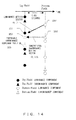
- Fig. 1 shows a block diagram of the configuration of the frame/field predictive encoding device.
- This encoding method utilizes the fact that a plurality of segments of motion picture data has high correlation in a time direction with each other.
- the operation shown in Fig. 1 is roughly described below.
- a subtracter 39 generates a differential image between an inputted original image and a predicted image, and an orthogonal transform unit 31, a quantization unit 32 and a coefficient entropy encoding unit 40 encode the differential image.
- An inverse quantization unit 33 and an inverse orthogonal transform unit 34 reproduce the differential image from the output of the quantization unit 32.
- a decoded image generation unit 35 decodes the encoded image using the reproduced differential image reproduced by the decoded image generation unit 35 and the predicted image used at the time of encoding.
- a decoded image storage unit 36 stores the reproduced image. Then, motion vector calculation unit 37 calculates a motion vector between the reproduced image and a subsequent input image, and a predicted image generation unit 38 generates a predicted image using the motion vector.
- the generated motion vector is encoded by a vector entropy encoding unit 41 and is outputted through aMUX 42 together with the encoded coefficient data encoded by the coefficient entropy encoding unit 40.
- the inter-frame/field predictive encoding method utilizes such a property.
- a transmitting device generates motion vector data indicating displacement from previous frame/field image to a target frame/field image, and differential data between a predicted image in the target frame/field which is generated from the previous frame/field image using its motion vector data and a real image in the target frame/field, and transmits the motion vector data and the differential data to a receiving device.
- the receiving device reproduces the image in the target frame/field from the received motion vector data and differential data.
- Figs. 2 and 3 show a format used to encode a field image that is commonly used in ISO/IEC MPEG-2/MPEG-4 (hereinafter called “MPEG-2” and “MPEG-4", respectively) and the final committee draft of ITU-T H.264/ISO/IEC MPEG-4 Part 10 (Advanced video coding (AVC)) ("Joint Final CommitteeDraft (JFCD) of Joint Video Specification (ITU-TREC, H.264
- JFCD Joint Final CommitteeDraft
- ISO/IEC JTC1/S029/WG11 MPEG02/N492 Joint Video Specification
- JVT-D157 Joint Video Specification
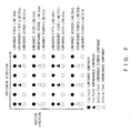
- each frame is composed of two fields: a top field and a bottom field.
- Fig. 2 shows the respective positions of a luminance pixels and a chrominance pixels, and a field to which each pixel belongs.
- odd number-ordered luminance lines such as a first luminance line 50a), a third luminance line (50b), a fifth luminance line (50c), a seventh luminance line (50d), etc.
- even number-ordered lines such as a second luminance line (51a), a fourth luminance line (51b), a sixth luminance line (51c), a eighth luminance line (51d), etc., belong to the bottom field.
- odd number-ordered chrominance lines such as a first chrominance line (52a), a third chrominance line (52b), etc.
- even number-ordered chrominance line such as a second chrominance (53a), a fourth chrominance line, etc., belong to the bottom field.
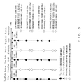
- Each of the top and bottom fields indicates an image at a different time. Next, the time/spatial disposition of the top and bottom fields is described with reference to Fig. 3 .
- the technology of the present invention relates to the vertical component of a motion vector. Therefore, in this specification, horizontal pixel components are not shown, and all the horizontal components of the motion vector are assumed to be 0 for convenience sake. However, in order to show conventional problems and the effects of the present invention, the positional relation between luminance and chrominance in each field is accurately shown.
- the vertical and horizontal axes represent the pixel position of a vertical component in each field and the elapse of time, respectively. Since there is no positional change in a field of the horizontal component of each image, in Fig. 3 , its horizontal pixel component is not shown nor is described.
- each time interval between adjacent top and bottom fields 64a: 65a, 65a: 64b, etc.
- each time interval between two consecutive top fields 64a: 64b, etc.
- two consecutive bottom field 65a: 65b, etc.
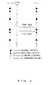
- Fig. 4 shows a method for constructing a frame using two consecutive fields (adjacent top and bottom fields) in a frame predictive mode.
- a frame is reconstructed by two time-consecutive fields (top and bottom fields).
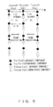
- Fig. 5 shows a frame predictive mode
- each frame such as 84a, 84b, 84c, etc.
- a frame to be encoded which is composed of top and bottom fields is encoded.
- a reference image one reference frame is constructed by two consecutive fields (top and bottom fields) stored for reference use, and is used to predict the target frame to be encoded. Then, these two frame images are encoded according to the process flow shown in Fig. 1 .
- a zero vector that is, (0,0) indicates a pixel located in the same spatial position.
- the motion vector (0,0) of a luminance pixel 82 that belongs to frame#2(84b) indicates the pixel position 81 of frame #1 (84a).
- Fig. 6 shows a predictive method in an inter-field predictive mode.
- an encoding target is one top field (94a, 94b, etc.) or bottom field (95a, 95b, etc.) that is inputted as an original image.
- a top field or bottom field that is stored before can be used.
- an original image field parity and a reference field parity are the same means that the original image field and the reference field both are top fields or bottom fields.
- an original image field (94b) and a reference field (94a) both are top fields.
- an original image field parity and a reference field parity are different means that one of original image and reference fields is a top field and the other is a bottom field.
- the original image field is a bottom field (95a) and the reference field is a top field (94a). Then, these original image and reference fields are encoded according to the process flow shown in Fig. 1 .
- a motion vector is calculated based on a pixel position in each frame/field.
- a conventional motion vector calculation method and a conventional pixel corresponding method used when a motion vector is given are described.
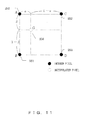
- Fig. 7 defines the coordinates of a frame/field image widely used in MPEG-2 coding, MPEG-1 coding, AVC FCD coding, etc.
- White circles in Fig. 7 are pixel definition positions in target frames/fields. In the coordinates of this frame/field image, the upper left corner is designated as the origin (0,0), and values 1, 2, 3, etc., are sequentially assigned to both horizontal and vertical pixel definition positions. Specifically, the coordinates of a pixel that are located at the n-th horizontal position and the m-th vertical position are (n,m). Similarly, the coordinates of a position interpolated among the pixels are also defined. Specifically, since a position 180 marked with a black circle in Fig.
- the coordinates of the position 180 is expressed as (1.5, 2).
- the coordinates of a pixel are defined in the same way as in Fig. 7 , based on pixel positions located in each field.
- Fig. 8 shows a conventional calculation method of a motion vector between corresponding pixels between fields.
- the definition of a motion vector requires the position of a coding field and the position of a reference field.
- Amotion vector is defined between these two points.
- a motion vector between a coding field coordinates 201(X s ,Y s ) and a reference field coordinates 202 (X d ,Y d ) is calculated.
- a motion vector is calculated by the same method described below, regardless of whether the coding field or reference field is a top field or a bottom field.
- coding field coordinates 201 (X s ,Y s ) and reference field coordinates 202 (X d ,Y d ) are inputted to a motion vector calculation unit 200, and as a motion vector 203 between these two points, (X d -X s ,Y d -Y s ) is given.
- Fig. 9 shows a conventional method for calculating a pixel that is pointed by a motion vector defined between fields.
- a motion vector is calculated by the method shown in Fig. 8 .
- the calculation of reference frame/field coordinates requires a coding frame/field position and a motion vector.
- a motion vector 211 (X,Y) is given for coding field coordinates 212(X s ,Y s ), and reference field coordinates can be calculated using both the motion vector 212 (X,Y) and the coding field coordinates 212 (X s ,Y s ).
- a reference field position is calculated by the same method described below, regardless of whether the coding field or reference field is a top field or a bottom field.
- a motion vector 211(X,Y) and coding field coordinates 212 (X s ,Y s ) are inputted to a pixel corresponding unit 210, and as reference field coordinates 213, coordinates (X s +X,Y s +Y) is given.
- the definition of the relation between a vector and a pixel position applies to both a luminance component and chrominance component.
- MPEG-1/MPEG-2/AVC FCD which all are general motion picture encoding methods
- the vector of a chrominance component is calculated by scaling down the luminance component.
- AVC FCD since the number of vertical pixels and that of horizontal pixels of a chrominance component are a half of those of a luminance component, respectively, it is specified that a motion vector used to calculate the predictive pixel of a chrominance component should be obtained by accurately scaling down the motion vector of the luminance component to a half.
- Fig. 10 shows a conventional method for calculating a chrominance motion vector using a luminance motion vector.
- a chrominance motion vector generation unit 220 can calculate a chrominance motion vector 222 according to the following equation.
- MVC_x ⁇ MVC_y MV_x / 2 , MV_y / 2
- This conventional calculation method can be used regardless of whether a motion vector is used for predicttion between fields with the same parity or between fields with different parity.
- Fig. 11 shows the calculation method of the interpolated pixel of a chrominance component that is defined in AVC FCD.
- a black circle and a white circle represent an integer pixel and an interpolated pixel, respectively.
- the horizontal coordinate of an interpolated pixel G(256) is obtained by internally dividing each horizontal coordinate between points A(250) and C(252) at a ratio ⁇ :1- ⁇
- the vertical coordinate can be obtained by internally dividing each vertical coordinate between points A(250) and B(251) at ⁇ :1- ⁇ .
- ⁇ and ⁇ are a value between 0 and 1.
- An interpolated pixel G(256) defined by such positions can be roughly calculated as follows using integer pixels A(250), B(251), C(252) and D(253), which are located around the interpolated pixel G(256), and using ⁇ and ⁇ .
- G 1 - ⁇ ⁇ 1 - ⁇ ⁇ A + 1 - ⁇ ⁇ ⁇ ⁇ B + ⁇ ⁇ 1 - ⁇ ⁇ C + ⁇ ⁇ ⁇ ⁇ D
- the interpolated pixel calculation method of a chrominance component using the method shown in Fig. 11 is just one example, and there is no problem in using another calculation method.
- bottom field 131 is to be encoded using top field 130.
- the vertical motion vector in the same line of each field is defined to be zero. Therefore, if a zero vector (0, 0) is assigned to a luminance pixel 133a that belongs to the second line of bottom field 131, this pixel can be predicted from a pixel 135a in top field130.
- a zero vector (0,0) is assigned to a chrominance pixel 133a which belongs to the first line of the bottom field 131
- this pixel is predicted from the pixel 137a which is in the first line of chrominance of the top field 130.
- a luminance pixel 133b in the third line and a chrominance pixel 134b, which belong to top field 132 are predicted from pixels 135b in the third line of luminance and 137b in the second line of chrominance in bottom field 131, respectively.
- chrominance pixels 134a and 134b should be predicted from the positions 136a and 136b, respectively, if a luminance motion vector is as it is.
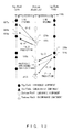
- Fig. 13 shows a conventional problem caused if a chrominance motion vector is conventionally calculated using a luminance motion vector when a reference field and a coding field are a bottom field and a top field, respectively.
- AVC FCD since, as is clear from equation (1), it is specified that the number of vertical and horizontal pixels of a chrominance component are a half of those of a luminance component, a motion vector used to calculate the predictive pixel of a chrominance should be scaled down to a half of the motion vector of a luminance component. This is regardless of whether a motion vector is used for predicttion between frames, between fields with the same parity or between fields with different parity.
- a coding field top field luminance pixel 140 in the first line has (0,1) as a predictive vector, and as a result, it points a bottom reference field luminance pixel position 141 in the second line as a predictive value.
- a chrominance motion vector that belongs to the same block is calculated to be (0,1/2), according to equation (1). If a prediction is made using motion vector (0, 1/2) as a predictive value of a coding field top field chrominance pixel 142 in the first line, a pixel position 143 is used as predicted value, which shifts downward by half a pixel from a pixel in the first line of a bottom reference field chrominance component.
- a luminance motion vector (0,1) and a chrominance vector (0,1/2) are not parallel. It is preferable to use a bottom reference field chrominance predictive pixel position 145 to which a chrominance motion vector parallel to a luminance motion vector is applied.
- Fig. 14 shows a conventional problem caused if a chrominance motion vector is calculated using a luminance motion vector when a reference field and a coding field are a top field and a bottom field, respectively.
- a bottom coding field luminance pixel 150 in the first line has (0,1) as a predictive vector, and as a result, it points a reference top field luminance pixel position 151 in the second line as a predictive value.
- a chrominance motion vector that belongs to the same block is calculated to be (0,1/2), according to equation (1). If a prediction is made using motion vector (0,1/2) as a predictive value of a bottom coding field chrominance pixel 152, a pixel position 153 is used as predicted value which is shifted by half a pixel from a top reference field chrominance pixel position 153 in the first line.
- a luminance motion vector (0,1) and a chrominance vector (0,1/2) are not parallel. It is preferable to use a top reference field chrominance predictive pixel position 155 to which a chrominance motion vector parallel to a luminance motion vector is applied.
- a pixel located in the position of a luminance component spatially deviated from that of the chrominance component is to be referenced, and a predictive image, in which a pixel located in the position of a luminance component is spatially deviated from that of the chrominance component, is generated not only for a zero vector but for all the vectors.
- vector are said to be parallel or not parallel by considering the case where the direction in time of a luminance motion vector and a chrominance motion vector, that is, time direction from coding field to reference field in included in a motion vector. The same is true below.
- the motion picture encoding device of the present invention for making the inter-field motion compensation of a motion picture signal composed of a plurality of fields comprises a plurality of chrominance motion vector generation units generating a chrominance motion vector using a luminance motion vector in a motion picture encoding device; and a selection unit selecting one of the chrominance motion vector generation units used to generate a chrominance vector, using the reference field parity and coding field parity of a motion vector.
- the chrominance motion vector generation unit selected by the selection unit generates the chrominance predictive vector, based on the motion vector information of luminance information.
- the motion picture decoding device of the present invention for making the inter-field motion compensation of a motion picture signal composed of a plurality of fields comprises a plurality of chrominance motion vector generation units generating a chrominance motion vector from a luminance motion vector; and a selection unit selecting one of the chrominance motion vector generation units used to generate a chrominance vector, using the reference field parity and coding field parity of a motion vector.
- the chrominance motion vector generation unit selected by the selection unit generates the chrominance predictive vector, based on the motion vector information of luminance information.
- the discrepancy of the chrominance motion vector caused by the difference of arrangement, or the way of assignment to a top and a bottom field of luminance pixel s and chrominance pixels is resolved.
- a chrominance motion vector which is parallel to a luminance motion vector is obtained even in the case of fields with different parity, and the problem of a shift of reference pixel position between luminance components and chrominance components in the conventional method, is resolved.
- the motion picture encoding device of the present invention for making the inter-fieldmotion compensation of a motion picture signal composed of a plurality of fields comprises a plurality of chrominance motion vector generation units generating a chrominance motion vector using a luminance motion vector; and a selection unit selecting one of the chrominance motion vector generation units used to generate a chrominance vector, using the respective parity of the reference field and a coding field of a motion vector.
- the chrominance motion vector generation unit selected by the selection unit generates the chrominance predictive vector, based on the motion vector information of luminance information.
- a chrominance motion vector from a coding field to a reference field is parallel to a luminance motion vector from the coding field to the reference field, the spatial shift of the luminance motion vector and that of the chrominance motion vector become the same, that is, the relation of the spatial positions of the luminance mot ion vector and the chrominance motion vector is preserved, then the color displacement between fields disappears.
- the plurality of chrominance motion vector generation units include the three following types.
- a first chrominance motion vector generation unit is selected by the selection unit when a reference field and a coding field have the same parity.
- a second chrominance motion vector generation unit is selected by the selection unit when a reference field and a coding field are a top field and a bottom field, respectively.
- a third chrominance motion vector generation unit is selected by the selection unit when a reference field and a coding field are a bottom field and a top field, respectively.
- a method for calculating a chrominance motion vector parallel to a luminance motion vector depends on the coding field parity and reference field parity of a luminance motion vector.
- the calculation method differs in the following three case: a case where the coding field parity and reference field parity are the same, a case where the coding field and reference field are top and bottom fields, respectively, and a case where the coding field and reference field are bottom and top fields, respectively. Therefore, in the present invention, an optimal one is selected from the three types of chrominance motion vector generation units calculating a chrominance motion vector parallel to a luminance motion vector, depending on the coding field and the reference field, and a chrominance motion vector is generated.
- the first chrominance motion vector generation unit calculates a chrominance motion vector as follows, assuming that a luminance motion vector indicating the vertical displacement of one luminance pixel of a field image by the value "1" of the vector component as units and a chrominance motion vector indicating the vertical displacement of one chrominance pixel of a field image by the value "1" of the vector component as units are MVy and MVCy, respectively.
- MVCy Mvy / 2
- the second chrominance motion vector generation unit calculates a chrominance motion vector as follows, assuming that a luminance motion vector indicating the vertical displacement of one luminance pixel of a field image by the value "1" of the vector component as units and a chrominance motion vector indicating the vertical displacement of one chrominance pixel of a field image by the value "1" of the vector component as units are MVy and MVCy, respectively.
- MVCy Mvy / 2 + 0.25
- the third chrominance motion vector generation unit calculates a chrominance motion vector as follows, assuming that a luminance motion vector indicating the vertical displacement of one luminance pixel of a field image by the value "1" of the vector component as units and a chrominance motion vector indicating the vertical displacement of one chrominance pixel of a field image by the value "1" of the vector component as units are MVy and MVCy, respectively.
- MVCy Mvy / 2 - 0.25
- the respective units of luminance and chrominance vectors vary, depending on its definition.
- a luminance motion vector indicates the displacement of one luminance moving pixel when the component of the luminance motion vector changes by value 4 and that a chrominance motion vector indicates the displacement of one chrominance moving pixel when the component of the chrominance motion vector changes by value 8
- the first chrominance motion vector generation unit calculates a chrominance motion vector as follows, assuming that a luminance motion vector and a chrominance motion vector are MVy and MVCy, respectively.
- MVCy Mvy
- the second chrominance motion vector generation uni t calculates a chrominance motion vector as follows, assuming that a luminance motion vector and a chrominance motion vector are MVy and MVCy, respectively.
- MVCy Mvy + 2
- the third chrominance motion vector generation unit calculates a chrominance motion vector as follows, assuming that a luminance motion vector and a chrominance motion vector are MVy and MVCy, respectively.
- MVCy Mvy - 2
- the motion picture decoding device of the present invention basically has the same functions as the motion picture encoding device, and operates in the same way.
- the preferred embodiments of the encoding device are mainly described below.
- the encoding device has the configuration described above. Since the present invention relates to the vertical component of a motion vector, it is assumed for convenience sake that the horizontal components of all the motion vectors are 0. In this case, the decoding device has the same configuration as the encoding device.
- Fig. 15 shows a method for calculating a chrominance motion vector using a luminance motion vector.
- the preferred embodiment of a device generating a chrominance motion vector using a luminance motion vector in a field prediction comprises three types or chrominance motion vector generation units and one selection unit.
- a given luminance motion vector 231 is (MV_x,MV_y).
- This luminance vector is inputted to all of a first chrominance motion vector generation unit 233, a second chrominance motion vector generation unit 234 and a third chrominance motion vector generation unit 235.
- their respective outputs are inputted to a selection unit 230.
- the selection unit 230 selects one of the respective outputs of the first, second and third chrominance motion vector generation units, based on information about the coding field parity 237 of the inputted motion vector and its reference field parity 238, and outputs it as a color motion vector 232 (MVC_x,MVC_y).
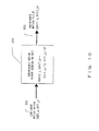
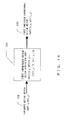
- Fig. 16 shows the operation of the first chrominance motion vector generation unit.
- a luminance motion vector 261 (MV_x,MV_y) is inputted to a first chrominance motion vector generation unit 260, and a first chrominance motion vector candidate 262 (MVC1_x, MVC1_y) is outputted.
- the chrominance motion vector generation unit 260 calculates the first chrominance motion vector candidate 262 as follows using the luminance motion vector 261.
- MVC ⁇ 1 _x , MVC ⁇ 1 _y MV_x / 2 , MV_y / 2
- the calculated first chrominance motion vector candidate 262 is outputted to the selection unit.
- Fig. 17 shows the operation of the second chrominance motion vector generation unit.
- a luminance motion vector 271 (MV_x,MV_y) is inputted to a second chrominance motion vector generation unit 270, and a second chrominance motion vector candidate 272 (MVC2_x, MVC2_y) is outputted.
- the chrominance motion vector generation unit 270 calculates the second chrominance motion vector candidate 272 as follows using the luminance motion vector 271.
- MVC ⁇ 2 _x , MVC ⁇ 2 _y MV_x / 2 , MV_y / 2 + 1 / 4
- the calculated second chrominance motion vector candidate 272 is outputted to the selection unit.
- Fig. 18 shows the operation of the third chrominance motion vector generation unit.
- a luminance motion vector 281 (MV_x,MV_y) is inputted to a third chrominance motion vector generation unit 280, and a third chrominance motion vector candidate 282 (MVC3_x, MVC3_y) is outputted.
- the chrominance motion vector generation unit 280 calculates the third chrominance motion vector candidate 282 as follows using the luminance motion vector 281.
- MVC ⁇ 3 _x , MVC ⁇ 3 _y MV_x / 2 , MV_y / 2 - 1 / 4
- the calculated third chrominance motion vector candidate 282 is outputted to the selection unit.
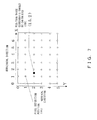
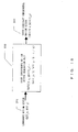
- Fig. 19 shows the operation of one preferred embodiment of the selection unit 240 of the present invention.
- a condition judgment table 241 is used for judgment of the coding field parity 247 of a motion vector and its reference field parity 248, and the selection information 249 of a chrominance motion vector generation unit to be selected is outputted.
- this condition judgment table 241 is used for outputting selection information indicating the selection of a first chrominance motion vector candidate 244. If reference field and coding field are top and bottom fields, respectively, the condition judgment table 241 is used for outputting selection information indicating the selection of a second chrominance motion vector candidate 245. If reference field and coding field are bottom and top fields, respectively, the condition judgment table 241 is used for outputting selection information indicating the selection of a third chrominance motion vector 246 candidate.
- the first, second or third chrominance motion vector candidates 244, 245 and 246 are connected to 262 shown in Fig. 16 , 272 shown in Fig. 17 and 282 shown in Fig. 18 , respectively. Then, a selector 243 selects one of the first, second and third chrominance motion vector candidates 244, 245 and 246, based on the selection information 249, and outputs (MVC_x,MVC_y) as its chrominance motion vector 242.
- Fig. 20 shows the operation of the present invention to calculate a chrominance vector using a luminance vector in the case where reference field and coding field are bottom and top fields, respectively.
- a luminance motion vector (MV_x,MV_y) used to predict a top coding field pixel 160 is assumed to be (0,1).
- a reference field bottom field luminance pixel position 161 is selected for the prediction of a luminance pixel 160.
- the calculation process of a chrominance motion vector to be used to predict a top coding field chrominance pixel 162 is described below with reference to Fig. 15 .
- reference field and coding field are bottom and top fields, respectively.
- the condition judgment table 241 shown in Fig. 19 is used for selecting selection information 249 about the third chrominance motion vector candidate.
- a bottom reference field chrominance pixel position 163 is used as a predicted value.
- the vertical positional relation between pixels corresponds to a real pixel.
- a luminance motion vector (0,1) and a chrominance motion vector (0, 1/4) are parallel.
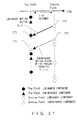
- Fig. 21 shows the operation of the present invention to calculate a chrominance vector using a luminance vector in the case where reference field and coding field are top and bottom fields, respectively.
- a luminance motion vector (MV_x,MV_y) used to predict a bottom coding field pixel 170 is assumed to be (0,1).
- a top reference field luminance pixel position 171 is selected for the prediction of a luminance pixel 170.
- the calculation process of a chrominance motion vector to be used to predict a bottom coding field chrominance pixel 172 is described below with reference to Fig. 15 .
- reference field and coding field are top and bottom fields, respectively.
- the condition judgment table 241 shown in Fig. 19 is used for selecting selection information 249 about the second chrominance motion vector candidate.
- a top reference field chrominance pixel position 173 is used as a predictive position.
- the vertical positional relation between pixels corresponds to a real one.
- a luminance motion vector (0,1) and a chrominance motion vector (0,3/4) are parallel.
- the result of the first chrominance motion vector generation unit 233 of the present invention which has the same configuration as a chrominance motion vector generation unit 220 is selected from the conventional luminance motion vector shown in Fig. 10 , and is used as a color motion vector 232. Since in this case, a chrominance motion vector calculated by the present invention is the same as conventional one, the description of this preferred embodiment is omitted here.
- equations (9), (10) and (11) vary depending on the units of luminance and chrominance motion vectors.
- Figs. 22 through 24 show another embodiment of the first chrominance motion vector generation unit, the second chrominance motion vector generation unit and the third chrominance motion vector generation unit of the present invention.
- the chrominance motion vector generation unit 270a calculates a second chrominance motion vector candidate 272a using a luminance motion vector 271a as follows.
- MVC ⁇ 2 _x , MVC ⁇ 2 _y MV_x , MV_y + 2
- the calculated second chrominance motion vector candidate 272a is outputted to a selection unit.
- a chrominance motion vector parallel to a luminance motion vector can also be calculated in fields with different parity, and the deviation in a reference pixel position between luminance and chrominance components, which are the conventional problem, can be solved accordingly.
Landscapes
- Engineering & Computer Science (AREA)
- Multimedia (AREA)
- Signal Processing (AREA)
- Compression Or Coding Systems Of Tv Signals (AREA)
- Color Television Systems (AREA)
Applications Claiming Priority (3)
| Application Number | Priority Date | Filing Date | Title |
|---|---|---|---|
| JP2002261427 | 2002-09-06 | ||
| JP2003289350A JP3791922B2 (ja) | 2002-09-06 | 2003-08-07 | 動画像復号化装置及び方法 |
| EP20030019607 EP1406448B1 (de) | 2002-09-06 | 2003-09-04 | Vorrichtungen zur Dekodierung von bewegten Bildern |
Related Parent Applications (2)
| Application Number | Title | Priority Date | Filing Date |
|---|---|---|---|
| EP03019607.5 Division | 2003-09-04 | ||
| EP20030019607 Division EP1406448B1 (de) | 2002-09-06 | 2003-09-04 | Vorrichtungen zur Dekodierung von bewegten Bildern |
Publications (2)
| Publication Number | Publication Date |
|---|---|
| EP2293573A1 true EP2293573A1 (de) | 2011-03-09 |
| EP2293573B1 EP2293573B1 (de) | 2016-09-28 |
Family
ID=31996117
Family Applications (16)
| Application Number | Title | Priority Date | Filing Date |
|---|---|---|---|
| EP20070011672 Expired - Lifetime EP1835758B1 (de) | 2002-09-06 | 2003-09-04 | Kodierung von Bewegtbildern |
| EP20070011668 Expired - Lifetime EP1835754B1 (de) | 2002-09-06 | 2003-09-04 | Dekodierung von Bewegtbildern |
| EP20070011666 Ceased EP1835752A3 (de) | 2002-09-06 | 2003-09-04 | Vorrichtung zur Kodierung von Filmen und Vorrichtung zur Dekodierung von Filmen |
| EP20100184267 Withdrawn EP2309753A1 (de) | 2002-09-06 | 2003-09-04 | Vorrichtung zur Kodierung von Filmen und Vorrichtung zur Dekodierung von Filmen |
| EP20070011670 Ceased EP1835756A3 (de) | 2002-09-06 | 2003-09-04 | Vorrichtung zur Kodierung von Filmen und Vorrichtung zur Dekodierung von Filmen |
| EP20070011671 Expired - Lifetime EP1835757B1 (de) | 2002-09-06 | 2003-09-04 | Kodierung von Bewegtbildern |
| EP10184258.1A Expired - Lifetime EP2293574B1 (de) | 2002-09-06 | 2003-09-04 | Verfahren zum Bewegtbilderdekodierung |
| EP20070011667 Expired - Lifetime EP1835753B1 (de) | 2002-09-06 | 2003-09-04 | Dekodierung von Bewegtbildern |
| EP20030019607 Expired - Lifetime EP1406448B1 (de) | 2002-09-06 | 2003-09-04 | Vorrichtungen zur Dekodierung von bewegten Bildern |
| EP10184244.1A Expired - Lifetime EP2293573B1 (de) | 2002-09-06 | 2003-09-04 | Bewegtbildkodierung |
| EP20100184260 Withdrawn EP2293575A1 (de) | 2002-09-06 | 2003-09-04 | Vorrichtung zur Kodierung von Filmen und Vorrichtung zur Dekodierung von Filmen |
| EP20100184252 Withdrawn EP2309752A1 (de) | 2002-09-06 | 2003-09-04 | Vorrichtung zur Kodierung von Filmen und Vorrichtung zur Dekodierung von Filmen |
| EP20070011673 Expired - Lifetime EP1835759B1 (de) | 2002-09-06 | 2003-09-04 | Vorrichtung und Verfahren zur Kodierung von bewegten Bildern |
| EP20070011665 Expired - Lifetime EP1835751B1 (de) | 2002-09-06 | 2003-09-04 | Vorrichtung und Verfahren zur Kodierung von bewegten Bildern |
| EP20070011669 Expired - Lifetime EP1835755B1 (de) | 2002-09-06 | 2003-09-04 | Vorrichtung und Verfahren zur Dekodierung von bewegten Bildern |
| EP10184370.4A Expired - Lifetime EP2293576B1 (de) | 2002-09-06 | 2003-09-04 | Bewegtbilderkodierung |
Family Applications Before (9)
| Application Number | Title | Priority Date | Filing Date |
|---|---|---|---|
| EP20070011672 Expired - Lifetime EP1835758B1 (de) | 2002-09-06 | 2003-09-04 | Kodierung von Bewegtbildern |
| EP20070011668 Expired - Lifetime EP1835754B1 (de) | 2002-09-06 | 2003-09-04 | Dekodierung von Bewegtbildern |
| EP20070011666 Ceased EP1835752A3 (de) | 2002-09-06 | 2003-09-04 | Vorrichtung zur Kodierung von Filmen und Vorrichtung zur Dekodierung von Filmen |
| EP20100184267 Withdrawn EP2309753A1 (de) | 2002-09-06 | 2003-09-04 | Vorrichtung zur Kodierung von Filmen und Vorrichtung zur Dekodierung von Filmen |
| EP20070011670 Ceased EP1835756A3 (de) | 2002-09-06 | 2003-09-04 | Vorrichtung zur Kodierung von Filmen und Vorrichtung zur Dekodierung von Filmen |
| EP20070011671 Expired - Lifetime EP1835757B1 (de) | 2002-09-06 | 2003-09-04 | Kodierung von Bewegtbildern |
| EP10184258.1A Expired - Lifetime EP2293574B1 (de) | 2002-09-06 | 2003-09-04 | Verfahren zum Bewegtbilderdekodierung |
| EP20070011667 Expired - Lifetime EP1835753B1 (de) | 2002-09-06 | 2003-09-04 | Dekodierung von Bewegtbildern |
| EP20030019607 Expired - Lifetime EP1406448B1 (de) | 2002-09-06 | 2003-09-04 | Vorrichtungen zur Dekodierung von bewegten Bildern |
Family Applications After (6)
| Application Number | Title | Priority Date | Filing Date |
|---|---|---|---|
| EP20100184260 Withdrawn EP2293575A1 (de) | 2002-09-06 | 2003-09-04 | Vorrichtung zur Kodierung von Filmen und Vorrichtung zur Dekodierung von Filmen |
| EP20100184252 Withdrawn EP2309752A1 (de) | 2002-09-06 | 2003-09-04 | Vorrichtung zur Kodierung von Filmen und Vorrichtung zur Dekodierung von Filmen |
| EP20070011673 Expired - Lifetime EP1835759B1 (de) | 2002-09-06 | 2003-09-04 | Vorrichtung und Verfahren zur Kodierung von bewegten Bildern |
| EP20070011665 Expired - Lifetime EP1835751B1 (de) | 2002-09-06 | 2003-09-04 | Vorrichtung und Verfahren zur Kodierung von bewegten Bildern |
| EP20070011669 Expired - Lifetime EP1835755B1 (de) | 2002-09-06 | 2003-09-04 | Vorrichtung und Verfahren zur Dekodierung von bewegten Bildern |
| EP10184370.4A Expired - Lifetime EP2293576B1 (de) | 2002-09-06 | 2003-09-04 | Bewegtbilderkodierung |
Country Status (7)
| Country | Link |
|---|---|
| US (15) | US8068542B2 (de) |
| EP (16) | EP1835758B1 (de) |
| JP (1) | JP3791922B2 (de) |
| KR (9) | KR100918744B1 (de) |
| CN (1) | CN1324904C (de) |
| CA (4) | CA2439886C (de) |
| DE (1) | DE60336880D1 (de) |
Families Citing this family (21)
| Publication number | Priority date | Publication date | Assignee | Title |
|---|---|---|---|---|
| JP3791922B2 (ja) * | 2002-09-06 | 2006-06-28 | 富士通株式会社 | 動画像復号化装置及び方法 |
| JP4145275B2 (ja) * | 2004-07-27 | 2008-09-03 | 富士通株式会社 | 動きベクトル検出・補償装置 |
| CN100359953C (zh) * | 2004-09-08 | 2008-01-02 | 华为技术有限公司 | 基于帧内编码的图像色度预测方法 |
| EP1732331A1 (de) * | 2005-06-08 | 2006-12-13 | BRITISH TELECOMMUNICATIONS public limited company | Videokodierung |
| KR100667806B1 (ko) * | 2005-07-07 | 2007-01-12 | 삼성전자주식회사 | 영상 부호화 및 복호화 방법 및 장치 |
| US8379723B2 (en) * | 2006-06-27 | 2013-02-19 | Intel Corporation | Chroma motion vector processing apparatus, system, and method |
| JP2009010492A (ja) * | 2007-06-26 | 2009-01-15 | Hitachi Ltd | 画像復号化装置及び画像変換回路 |
| JP4678015B2 (ja) * | 2007-07-13 | 2011-04-27 | 富士通株式会社 | 動画像符号化装置及び動画像符号化方法 |
| NO328906B1 (no) | 2007-12-19 | 2010-06-14 | Tandberg Telecom As | Fremgangsmate for forbedring av farveskarphet i video- og stillbilder |
| KR101291196B1 (ko) * | 2008-01-25 | 2013-07-31 | 삼성전자주식회사 | 영상의 부호화, 복호화 방법 및 장치 |
| KR101075328B1 (ko) * | 2008-08-21 | 2011-10-19 | 경희대학교 산학협력단 | 동영상의 복호화 방법 및 장치 |
| JP5578775B2 (ja) * | 2008-09-02 | 2014-08-27 | 富士通株式会社 | 符号化装置および復号装置 |
| TWI407802B (zh) * | 2009-04-22 | 2013-09-01 | Novatek Microelectronics Corp | 提升畫面品質的方法及顏色補償裝置與影像處理裝置 |
| KR101682147B1 (ko) * | 2010-04-05 | 2016-12-05 | 삼성전자주식회사 | 변환 및 역변환에 기초한 보간 방법 및 장치 |
| CN101883286B (zh) * | 2010-06-25 | 2012-12-05 | 无锡中星微电子有限公司 | 运动估计中的校准方法及装置、运动估计方法及装置 |
| JP2013121020A (ja) * | 2011-12-06 | 2013-06-17 | Sony Corp | 画像処理装置および方法 |
| WO2017123487A1 (en) * | 2016-01-15 | 2017-07-20 | Vid Scale, Inc. | System and method for enhanced motion compensation using adaptive filtering |
| CN108076347B (zh) * | 2016-11-15 | 2021-11-26 | 阿里巴巴集团控股有限公司 | 一种编码起始点的获取方法以及装置 |
| CN107360433B (zh) * | 2017-07-20 | 2020-06-19 | 北京奇艺世纪科技有限公司 | 一种帧间预测编码方法和装置 |
| CN109068140B (zh) * | 2018-10-18 | 2021-06-22 | 北京奇艺世纪科技有限公司 | 视频编码中运动向量的确定方法、装置及视频编解码设备 |
| WO2020192180A1 (zh) * | 2019-03-25 | 2020-10-01 | Oppo广东移动通信有限公司 | 图像分量的预测方法、编码器、解码器及计算机存储介质 |
Citations (2)
| Publication number | Priority date | Publication date | Assignee | Title |
|---|---|---|---|---|
| EP0863675A2 (de) * | 1997-03-07 | 1998-09-09 | General Instrument Corporation | Bewegungsbestimmung und -Kompensieurng von Video-Objektflächen für digitales Video mit Zwischenbild |
| EP0955607A2 (de) * | 1998-05-07 | 1999-11-10 | Sarnoff Corporation | Verfahren und Vorrichtung zur adaptiven massstäblichen Umformung von Bewegungsvektoren |
Family Cites Families (19)
| Publication number | Priority date | Publication date | Assignee | Title |
|---|---|---|---|---|
| EP0520765B1 (de) * | 1991-06-25 | 1999-05-12 | Canon Kabushiki Kaisha | Verfahren und Vorrichtung zur Detektion eines Bewegungsvektors sowie Kodierungsverfahren und Vorrichtung zur Anwendung eines solchen Verfahrens und Vorrichtung |
| JP2586260B2 (ja) * | 1991-10-22 | 1997-02-26 | 三菱電機株式会社 | 適応的ブロッキング画像符号化装置 |
| DE69329983T2 (de) * | 1992-08-21 | 2001-08-02 | Canon Kk | Bildverarbeitungsverfahren und -vorrichtung |
| JP3381077B2 (ja) * | 1992-12-04 | 2003-02-24 | ソニー株式会社 | 動画像復号装置 |
| JP2907663B2 (ja) | 1992-12-21 | 1999-06-21 | 松下電器産業株式会社 | 動きベクトル検出方法 |
| KR0151210B1 (ko) * | 1994-09-23 | 1998-10-15 | 구자홍 | 엠펙2를 수용하는 반화소 움직임 보상조절장치 |
| US6108039A (en) * | 1996-05-23 | 2000-08-22 | C-Cube Microsystems, Inc. | Low bandwidth, two-candidate motion estimation for interlaced video |
| JPH1013731A (ja) * | 1996-06-21 | 1998-01-16 | Canon Inc | 動きベクトル検出装置及び画像振れ補正装置 |
| US5905542A (en) * | 1996-12-04 | 1999-05-18 | C-Cube Microsystems, Inc. | Simplified dual prime video motion estimation |
| JP3522147B2 (ja) * | 1998-04-28 | 2004-04-26 | セイコーエプソン株式会社 | ハーフトーニング装置及び画像形成装置 |
| US6501799B1 (en) * | 1998-08-04 | 2002-12-31 | Lsi Logic Corporation | Dual-prime motion estimation engine |
| US6259741B1 (en) * | 1999-02-18 | 2001-07-10 | General Instrument Corporation | Method of architecture for converting MPEG-2 4:2:2-profile bitstreams into main-profile bitstreams |
| US6519005B2 (en) * | 1999-04-30 | 2003-02-11 | Koninklijke Philips Electronics N.V. | Method of concurrent multiple-mode motion estimation for digital video |
| JP3712906B2 (ja) | 2000-02-24 | 2005-11-02 | 日本放送協会 | 動きベクトル検出装置 |
| US6940557B2 (en) * | 2001-02-08 | 2005-09-06 | Micronas Semiconductors, Inc. | Adaptive interlace-to-progressive scan conversion algorithm |
| US6980596B2 (en) * | 2001-11-27 | 2005-12-27 | General Instrument Corporation | Macroblock level adaptive frame/field coding for digital video content |
| JP4644427B2 (ja) * | 2002-01-25 | 2011-03-02 | コナルカ テクノロジーズ インコーポレイテッド | 太陽電池に用いるための感光性ナノ粒子を低温で相互に結合させる方法及び該方法において用いられるポリマー連結剤溶液 |
| JP4100067B2 (ja) | 2002-07-03 | 2008-06-11 | ソニー株式会社 | 画像情報変換方法及び画像情報変換装置 |
| JP3791922B2 (ja) | 2002-09-06 | 2006-06-28 | 富士通株式会社 | 動画像復号化装置及び方法 |
-
2003
- 2003-08-07 JP JP2003289350A patent/JP3791922B2/ja not_active Expired - Lifetime
- 2003-09-04 EP EP20070011672 patent/EP1835758B1/de not_active Expired - Lifetime
- 2003-09-04 EP EP20070011668 patent/EP1835754B1/de not_active Expired - Lifetime
- 2003-09-04 DE DE60336880T patent/DE60336880D1/de not_active Expired - Lifetime
- 2003-09-04 EP EP20070011666 patent/EP1835752A3/de not_active Ceased
- 2003-09-04 EP EP20100184267 patent/EP2309753A1/de not_active Withdrawn
- 2003-09-04 EP EP20070011670 patent/EP1835756A3/de not_active Ceased
- 2003-09-04 EP EP20070011671 patent/EP1835757B1/de not_active Expired - Lifetime
- 2003-09-04 EP EP10184258.1A patent/EP2293574B1/de not_active Expired - Lifetime
- 2003-09-04 EP EP20070011667 patent/EP1835753B1/de not_active Expired - Lifetime
- 2003-09-04 EP EP20030019607 patent/EP1406448B1/de not_active Expired - Lifetime
- 2003-09-04 EP EP10184244.1A patent/EP2293573B1/de not_active Expired - Lifetime
- 2003-09-04 EP EP20100184260 patent/EP2293575A1/de not_active Withdrawn
- 2003-09-04 EP EP20100184252 patent/EP2309752A1/de not_active Withdrawn
- 2003-09-04 EP EP20070011673 patent/EP1835759B1/de not_active Expired - Lifetime
- 2003-09-04 KR KR20030061675A patent/KR100918744B1/ko active IP Right Grant
- 2003-09-04 EP EP20070011665 patent/EP1835751B1/de not_active Expired - Lifetime
- 2003-09-04 EP EP20070011669 patent/EP1835755B1/de not_active Expired - Lifetime
- 2003-09-04 EP EP10184370.4A patent/EP2293576B1/de not_active Expired - Lifetime
- 2003-09-05 CA CA 2439886 patent/CA2439886C/en not_active Expired - Lifetime
- 2003-09-05 CN CNB031566103A patent/CN1324904C/zh not_active Expired - Lifetime
- 2003-09-05 CA CA2779486A patent/CA2779486C/en not_active Expired - Lifetime
- 2003-09-05 CA CA2779469A patent/CA2779469C/en not_active Expired - Lifetime
- 2003-09-05 CA CA2895952A patent/CA2895952C/en not_active Expired - Lifetime
- 2003-09-05 US US10/655,397 patent/US8068542B2/en active Active
-
2005
- 2005-03-03 US US11/070,479 patent/US7826532B2/en active Active
- 2005-03-03 US US11/070,661 patent/US7809062B2/en active Active
- 2005-03-03 US US11/070,663 patent/US9124886B2/en active Active
-
2007
- 2007-03-30 US US11/694,359 patent/US8976868B2/en active Active
- 2007-03-30 US US11/694,292 patent/US9001894B2/en active Active
- 2007-04-04 KR KR1020070033474A patent/KR100909127B1/ko active IP Right Grant
- 2007-04-04 KR KR1020070033473A patent/KR100908955B1/ko active IP Right Grant
- 2007-04-04 KR KR1020070033472A patent/KR100788568B1/ko active IP Right Grant
- 2007-04-04 KR KR1020070033470A patent/KR100788567B1/ko active IP Right Grant
- 2007-09-20 KR KR1020070095745A patent/KR100788572B1/ko active IP Right Grant
- 2007-09-20 KR KR1020070095742A patent/KR100788569B1/ko active IP Right Grant
- 2007-09-20 KR KR1020070095743A patent/KR100788570B1/ko active IP Right Review Request
- 2007-09-20 KR KR1020070095744A patent/KR100788571B1/ko active IP Right Grant
-
2009
- 2009-03-30 US US12/414,105 patent/US8861604B2/en active Active
- 2009-03-30 US US12/414,127 patent/US8660184B2/en active Active
-
2010
- 2010-04-01 US US12/752,399 patent/US8509307B2/en not_active Expired - Lifetime
- 2010-04-27 US US12/767,929 patent/US8665956B2/en not_active Expired - Lifetime
- 2010-04-27 US US12/768,105 patent/US8665957B2/en not_active Expired - Lifetime
- 2010-04-27 US US12/768,109 patent/US8654851B2/en not_active Expired - Lifetime
-
2014
- 2014-08-29 US US14/472,616 patent/US9432677B2/en not_active Expired - Lifetime
-
2015
- 2015-08-24 US US14/833,616 patent/US9544609B2/en not_active Expired - Lifetime
-
2016
- 2016-01-13 US US14/994,744 patent/US9549192B2/en not_active Expired - Lifetime
Patent Citations (2)
| Publication number | Priority date | Publication date | Assignee | Title |
|---|---|---|---|---|
| EP0863675A2 (de) * | 1997-03-07 | 1998-09-09 | General Instrument Corporation | Bewegungsbestimmung und -Kompensieurng von Video-Objektflächen für digitales Video mit Zwischenbild |
| EP0955607A2 (de) * | 1998-05-07 | 1999-11-10 | Sarnoff Corporation | Verfahren und Vorrichtung zur adaptiven massstäblichen Umformung von Bewegungsvektoren |
Non-Patent Citations (2)
| Title |
|---|
| "Joint Final Committee Draft (JFCD) of Joint Video Specification (ITU-TREC, H. 264 | ISO/ IEC 14496-10 AVC)", JVT-D157, OR ISO/IEC JTC1/SO29/MG11 MPEG02/N492, July 2002 (2002-07-01) |
| "MPEG-4 VIDEO VERIFICATION MODEL VERSION 7.0", INTERNATIONAL ORGANIZATION FOR STANDARDIZATION - ORGANISATION INTERNATIONALE DE NORMALISATION, BRISTO, UK, APRIL 1997, vol. N1642, 1 April 1997 (1997-04-01), pages 1,12 - 14, XP002600135 * |
Also Published As
Similar Documents
| Publication | Publication Date | Title |
|---|---|---|
| US9432677B2 (en) | Motion picture encoding device and motion picture decoding device | |
| CA2591685C (en) | A device and method for providing inter-field motion compensation for chrominance motion vectors while decoding motion pictures |
Legal Events
| Date | Code | Title | Description |
|---|---|---|---|
| PUAI | Public reference made under article 153(3) epc to a published international application that has entered the european phase |
Free format text: ORIGINAL CODE: 0009012 |
|
| AC | Divisional application: reference to earlier application |
Ref document number: 1406448 Country of ref document: EP Kind code of ref document: P |
|
| AK | Designated contracting states |
Kind code of ref document: A1 Designated state(s): DE FI FR GB NL SE |
|
| 17P | Request for examination filed |
Effective date: 20110906 |
|
| 17Q | First examination report despatched |
Effective date: 20151202 |
|
| REG | Reference to a national code |
Ref country code: DE Ref legal event code: R079 Ref document number: 60349452 Country of ref document: DE Free format text: PREVIOUS MAIN CLASS: H04N0007260000 Ipc: H04N0019105000 |
|
| GRAP | Despatch of communication of intention to grant a patent |
Free format text: ORIGINAL CODE: EPIDOSNIGR1 |
|
| RIC1 | Information provided on ipc code assigned before grant |
Ipc: H04N 19/186 20140101ALI20160513BHEP Ipc: H04N 19/61 20140101ALI20160513BHEP Ipc: H04N 19/51 20140101ALI20160513BHEP Ipc: H04N 19/105 20140101AFI20160513BHEP Ipc: H04N 19/176 20140101ALI20160513BHEP Ipc: H04N 19/16 20140101ALI20160513BHEP Ipc: H04N 19/513 20140101ALI20160513BHEP |
|
| INTG | Intention to grant announced |
Effective date: 20160620 |
|
| GRAS | Grant fee paid |
Free format text: ORIGINAL CODE: EPIDOSNIGR3 |
|
| GRAA | (expected) grant |
Free format text: ORIGINAL CODE: 0009210 |
|
| AC | Divisional application: reference to earlier application |
Ref document number: 1406448 Country of ref document: EP Kind code of ref document: P |
|
| AK | Designated contracting states |
Kind code of ref document: B1 Designated state(s): DE FI FR GB NL SE |
|
| REG | Reference to a national code |
Ref country code: GB Ref legal event code: FG4D |
|
| REG | Reference to a national code |
Ref country code: DE Ref legal event code: R096 Ref document number: 60349452 Country of ref document: DE |
|
| REG | Reference to a national code |
Ref country code: NL Ref legal event code: FP |
|
| REG | Reference to a national code |
Ref country code: SE Ref legal event code: TRGR |
|
| REG | Reference to a national code |
Ref country code: DE Ref legal event code: R097 Ref document number: 60349452 Country of ref document: DE |
|
| REG | Reference to a national code |
Ref country code: FR Ref legal event code: PLFP Year of fee payment: 15 |
|
| PLBE | No opposition filed within time limit |
Free format text: ORIGINAL CODE: 0009261 |
|
| STAA | Information on the status of an ep patent application or granted ep patent |
Free format text: STATUS: NO OPPOSITION FILED WITHIN TIME LIMIT |
|
| 26N | No opposition filed |
Effective date: 20170629 |
|
| REG | Reference to a national code |
Ref country code: FR Ref legal event code: PLFP Year of fee payment: 16 |
|
| PGFP | Annual fee paid to national office [announced via postgrant information from national office to epo] |
Ref country code: NL Payment date: 20220819 Year of fee payment: 20 |
|
| PGFP | Annual fee paid to national office [announced via postgrant information from national office to epo] |
Ref country code: SE Payment date: 20220811 Year of fee payment: 20 Ref country code: GB Payment date: 20220728 Year of fee payment: 20 Ref country code: FI Payment date: 20220909 Year of fee payment: 20 Ref country code: DE Payment date: 20220803 Year of fee payment: 20 |
|
| PGFP | Annual fee paid to national office [announced via postgrant information from national office to epo] |
Ref country code: FR Payment date: 20220808 Year of fee payment: 20 |
|
| REG | Reference to a national code |
Ref country code: DE Ref legal event code: R071 Ref document number: 60349452 Country of ref document: DE |
|
| REG | Reference to a national code |
Ref country code: NL Ref legal event code: MK Effective date: 20230903 |
|
| REG | Reference to a national code |
Ref country code: GB Ref legal event code: PE20 Expiry date: 20230903 |
|
| PG25 | Lapsed in a contracting state [announced via postgrant information from national office to epo] |
Ref country code: GB Free format text: LAPSE BECAUSE OF EXPIRATION OF PROTECTION Effective date: 20230903 |
|
| REG | Reference to a national code |
Ref country code: SE Ref legal event code: EUG |