EP2293552A2 - Rundfunk-Aufzeichnungsvorrichtung und Rundfunk-Aufzeichnungsverfahren - Google Patents
Rundfunk-Aufzeichnungsvorrichtung und Rundfunk-Aufzeichnungsverfahren Download PDFInfo
- Publication number
- EP2293552A2 EP2293552A2 EP20100161975 EP10161975A EP2293552A2 EP 2293552 A2 EP2293552 A2 EP 2293552A2 EP 20100161975 EP20100161975 EP 20100161975 EP 10161975 A EP10161975 A EP 10161975A EP 2293552 A2 EP2293552 A2 EP 2293552A2
- Authority
- EP
- European Patent Office
- Prior art keywords
- transport stream
- time information
- section
- controller
- signal
- Prior art date
- Legal status (The legal status is an assumption and is not a legal conclusion. Google has not performed a legal analysis and makes no representation as to the accuracy of the status listed.)
- Withdrawn
Links
Images


Classifications
-
- H—ELECTRICITY
- H04—ELECTRIC COMMUNICATION TECHNIQUE
- H04N—PICTORIAL COMMUNICATION, e.g. TELEVISION
- H04N5/00—Details of television systems
- H04N5/76—Television signal recording
-
- H—ELECTRICITY
- H04—ELECTRIC COMMUNICATION TECHNIQUE
- H04N—PICTORIAL COMMUNICATION, e.g. TELEVISION
- H04N21/00—Selective content distribution, e.g. interactive television or video on demand [VOD]
- H04N21/40—Client devices specifically adapted for the reception of or interaction with content, e.g. set-top-box [STB]; Operations thereof
- H04N21/41—Structure of client; Structure of client peripherals
- H04N21/426—Internal components of the client ; Characteristics thereof
- H04N21/42661—Internal components of the client ; Characteristics thereof for reading from or writing on a magnetic storage medium, e.g. hard disk drive
-
- H—ELECTRICITY
- H04—ELECTRIC COMMUNICATION TECHNIQUE
- H04N—PICTORIAL COMMUNICATION, e.g. TELEVISION
- H04N21/00—Selective content distribution, e.g. interactive television or video on demand [VOD]
- H04N21/40—Client devices specifically adapted for the reception of or interaction with content, e.g. set-top-box [STB]; Operations thereof
- H04N21/43—Processing of content or additional data, e.g. demultiplexing additional data from a digital video stream; Elementary client operations, e.g. monitoring of home network or synchronising decoder's clock; Client middleware
- H04N21/4302—Content synchronisation processes, e.g. decoder synchronisation
- H04N21/4305—Synchronising client clock from received content stream, e.g. locking decoder clock with encoder clock, extraction of the PCR packets
-
- H—ELECTRICITY
- H04—ELECTRIC COMMUNICATION TECHNIQUE
- H04N—PICTORIAL COMMUNICATION, e.g. TELEVISION
- H04N21/00—Selective content distribution, e.g. interactive television or video on demand [VOD]
- H04N21/40—Client devices specifically adapted for the reception of or interaction with content, e.g. set-top-box [STB]; Operations thereof
- H04N21/43—Processing of content or additional data, e.g. demultiplexing additional data from a digital video stream; Elementary client operations, e.g. monitoring of home network or synchronising decoder's clock; Client middleware
- H04N21/434—Disassembling of a multiplex stream, e.g. demultiplexing audio and video streams, extraction of additional data from a video stream; Remultiplexing of multiplex streams; Extraction or processing of SI; Disassembling of packetised elementary stream
- H04N21/4344—Remultiplexing of multiplex streams, e.g. by modifying time stamps or remapping the packet identifiers
-
- H—ELECTRICITY
- H04—ELECTRIC COMMUNICATION TECHNIQUE
- H04N—PICTORIAL COMMUNICATION, e.g. TELEVISION
- H04N5/00—Details of television systems
- H04N5/76—Television signal recording
- H04N5/765—Interface circuits between an apparatus for recording and another apparatus
-
- H—ELECTRICITY
- H04—ELECTRIC COMMUNICATION TECHNIQUE
- H04N—PICTORIAL COMMUNICATION, e.g. TELEVISION
- H04N5/00—Details of television systems
- H04N5/76—Television signal recording
- H04N5/78—Television signal recording using magnetic recording
- H04N5/781—Television signal recording using magnetic recording on disks or drums
-
- H—ELECTRICITY
- H04—ELECTRIC COMMUNICATION TECHNIQUE
- H04N—PICTORIAL COMMUNICATION, e.g. TELEVISION
- H04N5/00—Details of television systems
- H04N5/76—Television signal recording
- H04N5/907—Television signal recording using static stores, e.g. storage tubes or semiconductor memories
-
- H—ELECTRICITY
- H04—ELECTRIC COMMUNICATION TECHNIQUE
- H04N—PICTORIAL COMMUNICATION, e.g. TELEVISION
- H04N9/00—Details of colour television systems
- H04N9/79—Processing of colour television signals in connection with recording
- H04N9/87—Regeneration of colour television signals
- H04N9/8715—Regeneration of colour television signals involving the mixing of the reproduced video signal with a non-recorded signal, e.g. a text signal
Definitions
- the present invention relates to a broadcast recording apparatus and a method for partializing a transport stream (TS) recorded on a storage medium.
- TS transport stream
- one broadcast TS contains a plurality of channels.
- a process of extracting TS packets belonging to a specific channel, generating some sections corresponding to the TS packets and re-multiplexing section data is performed as a process called partializing.
- a maximum period (time) of insertion is determined according to the standard.
- the method of re-multiplexing section data can be completed when a process of generating and inserting a section is repeated at regular intervals of a period not larger than the maximum period.
- a TS input rate which is a rate of the TS input to a partial TS generator is not equal to a real-time rate which is a rate of broadcasting.
- it is therefore necessary to change a section generating/inserting interval in accordance with the TS input rate (sections inserted at intervals of 2 sec in real time must be inserted at intervals of 1 sec if the TS input rate is doubled).
- the TS input rate however varies indefinitely. For this reason, there is a possibility that the TS input rate per se will be unable to be acquired or that the TS input rate will be too late far the rye-multiplexing process because the TS input rate affected by the reading rate and other processing rates exceeds the TS packet generating/inserting rate even when the TS input rate can be acquired. That is, in the section data re-multiplexing method according to the background art, the maximum period of insertion cannot be warranted.
- a digital broadcast receiver relevantly described in JP-A-2008-17328 is configured so that an IP stream of all IP broadcast channels is directly extracted at intervals of a predetermined time and stored in an HDD, IP packets of a channel to be viewed are extracted from the HDD, a time stamp-including transport stream is separated from the IP packets, and fluctuation is corrected based on the time stamps to perform a synchronizing process.
- section inserting method according to the background art, there is however a problem that section data cannot be inserted at correct timing when the stream to be recorded is not fed at a uniform rate.
- One of objects of the invention is to provide a technique for ensuring section insertion in re-multiplexing of section data of a broadcast channel.
- a broadcast recording apparatus including: a storage medium configured to store a transport stream of broadcasting signal; and a re-multiplexer configured to: partialize a specific channel in the transport stream to output a partial transport stream; acquire time information contained in the transport stream; and insert section data into the partial transport stream based on the time information.
- a broadcast recording method including:
- Digital television broadcasting has been standardized and description of details defined by the standard will be omitted in this specification.
- Fig. 1 shows an environment in use of a digital television broadcast recording apparatus 101 according to the first embodiment of the invention.
- a BS/CS digital broadcast receiving antenna 121 and a digital terrestrial broadcast receiving antenna 122 are connected to the input side of the digital television broadcast recording apparatus 101 while a digital television broadcast receiver 111 is connected to the output side of the digital television broadcast recording apparatus 101.
- the digital television broadcast recording apparatus 101 can record programs as a full TS by demodulating a received digital television broadcast signal and decoding the demodulated signal.
- the digital television broadcast recording apparatus 101 further can feed video and audio signals of a program on the air or a recorded program to the digital television broadcast receiver 111 so that a user can view the program by the digital television broadcast receiver 111 which is a portion for displaying these signals.
- the digital television broadcast recording apparatus 101 can record multi-channel programs and may be therefore configured to have a plurality of receiving circuits such as tuners, as well as the BS/CS digital broadcast receiving circuit and the digital terrestrial broadcast receiving circuit.
- a hardware configuration of the digital television broadcast recording apparatus 101 will be described next.
- Fig. 2 is a block diagram showing a main signal processing system in the digital television broadcast recording apparatus 101.
- a satellite digital television broadcast signal received through the BS/CS digital broadcast receiving antenna 121 is fed to a satellite digital broadcast tuner 202a through an input terminal 201.
- the tuner 202a selects a broadcast signal of a desired channel based on a control signal given from a controller 205 and outputs the selected broadcast signal to a phase shift keying (PSK) demodulator 202b.
- PSK phase shift keying
- the PSK demodulator 202b demodulates the broadcast signal selected by the tuner 202a based on a control signal given from the controller 205 to obtain a transport stream (TS) containing a desired program and outputs the TS to a TS decoder 202a.
- TS transport stream
- the TS decoder 202c performs a TS decoding process on a transport stream (TS)-multiplexed signal based on the control signal from the controller 205 and the input signal from the PSK demodulator 202b, obtains a packetized elementary stream (PES) by depacketizing digital video and audio signals of the desired program and outputs the PES to an STD buffer (not shown) in a signal processor 206.
- TS transport stream
- PES packetized elementary stream
- the TS decoder 202c further outputs section information fed from the digital broadcast to a section processor (not shown) in the signal processor 206.
- a digital terrestrial television broadcast signal received through the digital terrestrial broadcast receiving antenna 122 is fed to a digital terrestrial broadcast tuner 204a through an input terminal 203.
- the tuner 204a selects a broadcast signal of a desired channel based on a control signal given from the controller 205 and outputs the selected broadcast signal to an orthogonal frequency division multiplexing (OFDM) demodulator 204b.
- OFDM orthogonal frequency division multiplexing
- the OFDM demodulator 204b demodulates the broadcast signal selected by the tuner 204a based on a control signal given from the controller 205 to obtain a transport stream (TS) containing a desired program and outputs the TS to a TS decoder 204c.
- TS transport stream
- the TS decoder 204c performs a TS decoding process on a transport stream (TS)-multiplexed signal based on the control signal from the controller 205 and the input signal from the OFDM demodulator 204b, obtains a packetized elementary stream (PES) by depacketizing digital video and audio signals of the desired program and outputs the PES to the STD buffer in the signal processor 206.
- TS transport stream
- PES packetized elementary stream
- the TS decoder 204c further outputs section information fed from the digital broadcast to the section processor 206a in the signal processor 206.
- the signal processor 206 selectively applies predetermined digital signal processing to the PESs which are digital video and audio signals fed from the TS decoder 202c and the TS decoder 204c respectively, and outputs the processed signals to a graphic processor 207 and an audio processor 208 respectively.
- the signals obtained by selectively applying predetermined digital signal processing to the PESs which are digital video and audio signals fed from the TS decoder 202c and the TS decoder 204c respectively are recorded on a recorder (e.g. HDD) 270 through the controller 205.
- the signal processor 206 applies predetermined digital signal processing to data of a recorded program read from the recorder (e.g. HDD) 270 through the controller 205 and outputs the processed signals to the graphic processor 207 and the audio processor 208 respectively.
- Various data (B-CAS scrambling key information, etc.) for acquiring programs, electronic program guide (EPG) information, program attribute information (program genre, etc.) subtitle information (service information, SI and PSI), etc. are input to the controller 205 through the signal processor 206.
- the controller 205 performs an image generating process for displaying EPG and subtitle information from these pieces of input information and outputs the generated image information to the graphic processor 207.
- the controller 205 further has a function of controlling program recording and program scheduled recording.
- the controller 205 displays electronic program guide (EPG) information on an external display device (such as a digital television set) and sets the content of scheduling in a predetermined storage unit in accordance with user's inputting through an user interface 220 or a remote controller 221.
- EPG electronic program guide
- the controller 205 controls the tuners 202a and 204a, the PSK and OFDM demodulators 202b and 204b, the TS decoders 202c and 204c and the signal processor 206 so that the scheduled program can be recorded at the set time.
- the controller 205 controls respective devices to perform recording regardless of time.
- the section processor 206a in the signal processor 206 extracts various data for acquiring programs, electronic program guide (EPG) information, program attribute information (program genre, etc.) subtitle information (service information, SI and PSI), etc. from section information input from the TS decoder 202c (204c) and outputs the extracted information to the controller 205.
- EPG electronic program guide
- program attribute information program genre, etc.
- subtitle information service information, SI and PSI
- the graphic processor 207 has a function of combining a digital video signal fed from an AV decoder (not shown) in the signal processor 206, an OSD signal generated by an on screen display (OSD) signal generator 209, image data based on data broadcasting and EPG and subtitle signals generated by the controller 205, and outputting the resulting composite signal to a video processor 210.
- an AV decoder not shown
- OSD on screen display
- the graphic processor 207 When a subtitle based on subtitle broadcasting is to be displayed, the graphic processor 207 performs a process of superposing subtitle information on the video signal based on the subtitle information controlled by the controller 205.
- the digital video signal output from the graphic processor 207 is fed to the video processor 210.
- the video processor 210 converts the input digital video signal into an analog video signal of a format allowed to be displayed on the digital television broadcast receiver 111 and outputs the analog video signal to the digital television broadcast receiver 111 through an output terminal 211 so that video is displayed.
- the audio processor 208 converts the input digital audio signal into an analog audio signal of a format allowed to be reproduced by the digital television broadcast receiver 111 and outputs the analog audio signal to the digital television broadcast receiver 111 through an output terminal 212 so that audio is reproduced.
- the digital television broadcast recording apparatus 101 is configured so that all operations inclusive of the aforementioned various receiving operations are generally controlled by the controller 205.
- the controller 205 has a built-in central processing unit (CPU), etc.
- the controller 205 receives operation information from the user interface 220 or receives operation information sent out from the remote controller 221 through a photo acceptor 222, and controls respective portions so that the content of the operation is reflected.
- the controller 205 mainly uses a read only memory ROM) 205a, an random access memory (RAM) 205b and a nonvolatile memory 205c. Control programs executed by the CPU are stored in the ROM 205a.
- the RAM 205b provides a working area to the CPU. Various types of setting information, control information, etc. are stored in the nonvolatile memory 205c.
- the controller 205 is connected to a card holder 225 in which a first memory card 224 can be mounted, through a card interface (I/F) 223. Accordingly, the controller 205 can exchange information with the first memory card 224 mounted in the card holder 225, through the card I/F 223.
- I/F card interface
- the controller 205 is further connected to a card holder 228 in which a second memory card 227 can be mounted, through a card I/F 226. Accordingly, the controller 205 can exchange information with the second memory card 27 mounted in the card holder 228, through the card I/F 226.
- the controller 205 is further connected to a first LAN terminal 230 through a communication I/F 229. Accordingly, the controller 205 can exchange information with an LAN-support device (e.g. external HDD) connected to the first LAN terminal 230, through the communication T/F 229.
- the controller 205 has a dynamic host configuration protocol (DHCP) server function which allocates an internet protocol (IP) address to the LAN-support device connected to the first LAN terminal 230 in order to control the LAN-support device.
- DHCP dynamic host configuration protocol
- the controller 205 is further connected to a second LAN terminal 232 through a communication I/F 231. Accordingly, the controller 205 can exchange information with any type LAN-support device connected to the second LAN terminal 232, through the communication I/F 231.
- the controller 205 is further connected to a USB terminal 234 through a USB I/F 233. Accordingly, the controller 205 can exchange information with any type device connected to the USB terminal 234, through the USB I/F 233.
- the controller 205 is further connected to an i.LINK terminal 236 through an i.LINK I/F 235. Accordingly, the controller 205 can exchange information with any type device connected to the i.LINK terminal 236, through the i.LINK I/F 235.
- the controller 205 further has a section extraction control function 250 as a function portion related to the invention.
- the controller 205 performs the following section extraction control by using the section extraction control function 250.
- section data decoded by the TS decoder 202c (204c) are separated and extracted in accordance with each section.
- the data sequence extracted in accordance with each section is reconstructed (section generation) and the reconstructed data sequence is fed to the signal processor 206 in accordance with each channel.
- the section extraction control function 250 of the controller 205 performs respective section extraction processing control for a process of recording a data stream of each program to be recorded (recording process).
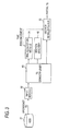
- Fig. 3 is a functional block diagram focusing on the controller 205 of Fig. 2 showing an embodiment of the invention.
- a broadcast TS which is a full TS is directly recorded on an HDD 31 corresponding to the recorder 270 shown in Fig. 2 .
- An input module 32 in the controller 205 reads the broadcast TS from the HDD 31 at a higher speed than the speed of broadcasting.
- a TS demultiplexer 43 demultiplexes the TS into a section, a program clock reference (PCR), an audio elementary stream (ES) and a video elementary stream (ES) and feeds these demultiplexed pieces of data to respective processors in a rear stage. For example, the PCR is fed to a time acquisition module 34.
- PCR program clock reference
- ES audio elementary stream
- ES video elementary stream
- the time acquisition module 34 acquires time information in the stream from the PCR and sends the time information to a section re-multiplexer 35 when a predetermined time interval has passed.
- the section re-multiplexer 35 Upon reception of the time information from the time acquisition module 34, the section re-multiplexer 35 performs section generation and insertion on the partial TS stream fed from the TS demultiplexer 43.
- a section analyzer 46 analyzes various types of sections necessary for partializing.
- the maximum period of section insertion into the partial TS is defined by ARIB.
- section data can be re-multiplexed at intervals of a designated constant time. Accordingly, the maximum period of insertion can be prevented from exceeding a standard value at the time of re-multiplexing of section data.
- Second embodiment of the invention will be described with reference to Figs. 1 and 2 and Fig. 4 . Description of parts common to those of the first embodiment will be omitted.
- Fig. 4 is a block diagram showing the second embodiment of the invention.
- a broadcast TS is converted into a time stamp-including TTS in advance by the controller 205, so that the TTS is recorded on an HDD 41.
- An input module 42 reads the TTS from the HDD 41.
- the TS demultiplexer 43 demultiplexes the TTS into a section, a PCR, an audio ES and a video ES and feeds these demultiplexed pieces of data to respective processors in a rear stage.
- a time acquisition module 44 acquires time information in the stream from the TTS. When a predetermined time interval has passed, the time acquisition module 44 sends the time information to a section re-multiplexer 45 and instructs the input module 42 to pause.
- the section re-multiplexer 45 Upon reception of the time information from the time acquisition module 44, the section re-multiplexer 45 performs section generation and insertion on the partial TS stream fed from the TS demultiplexer 43 and then instructs the input module 42 to resume the inputting.
- the section analyzer 46 analyzes various types of sections necessary for partializing.
- the point of the aforementioned embodiments is as follows.
- time information in a stream is acquired and sent at intervals of a designated time and, at the same time, inputting of the stream input module is stopped unless insertion is completed.
- the section re-multiplexer 45 Upon reception of the time information, the section re-multiplexer 45 performs section generation and insertion. When insertion is completed, the section re-multiplexer 45 instructs the stream input module to resume the inputting.
- section data can be re-multiplexed at intervals of a designated constant time. Accordingly, the maximum period of insertion can be prevented from exceeding a standard value at the time of re-multiplexing of section data.
- the storage medium may be not only an HDD but also an SD memory card.
- Constituent components disclosed in the aforementioned embodiments may be combined suitably to form various inventions. For example, some constituent components may be removed from all constituent components disclosed in any one of the embodiments. In addition, constituent components disclosed in different embodiments may be combined suitably.
Landscapes
- Engineering & Computer Science (AREA)
- Multimedia (AREA)
- Signal Processing (AREA)
- Television Signal Processing For Recording (AREA)
- Two-Way Televisions, Distribution Of Moving Picture Or The Like (AREA)
Applications Claiming Priority (1)
| Application Number | Priority Date | Filing Date | Title |
|---|---|---|---|
| JP2009176740A JP2011035455A (ja) | 2009-07-29 | 2009-07-29 | 放送録画装置および放送録画方法 |
Publications (1)
| Publication Number | Publication Date |
|---|---|
| EP2293552A2 true EP2293552A2 (de) | 2011-03-09 |
Family
ID=42937204
Family Applications (1)
| Application Number | Title | Priority Date | Filing Date |
|---|---|---|---|
| EP20100161975 Withdrawn EP2293552A2 (de) | 2009-07-29 | 2010-05-05 | Rundfunk-Aufzeichnungsvorrichtung und Rundfunk-Aufzeichnungsverfahren |
Country Status (2)
| Country | Link |
|---|---|
| EP (1) | EP2293552A2 (de) |
| JP (1) | JP2011035455A (de) |
Citations (1)
| Publication number | Priority date | Publication date | Assignee | Title |
|---|---|---|---|---|
| JP2008017328A (ja) | 2006-07-07 | 2008-01-24 | Mitsubishi Electric Corp | 録画機能付デジタル放送受信機 |
Family Cites Families (5)
| Publication number | Priority date | Publication date | Assignee | Title |
|---|---|---|---|---|
| JP3592186B2 (ja) * | 2000-03-22 | 2004-11-24 | シャープ株式会社 | データ記録再生装置 |
| KR100752482B1 (ko) * | 2001-07-07 | 2007-08-28 | 엘지전자 주식회사 | 멀티채널 스트림 기록 재생장치 및 방법 |
| JP3858975B2 (ja) * | 2001-10-02 | 2006-12-20 | ソニー株式会社 | トランスポートストリーム処理装置および方法 |
| JP2003228920A (ja) * | 2002-01-31 | 2003-08-15 | Toshiba Corp | 番組配列情報を記憶する情報記憶媒体、情報記録装置、及び情報再生装置 |
| JP2009111955A (ja) * | 2007-11-01 | 2009-05-21 | Panasonic Corp | ストリーム再生装置 |
-
2009
- 2009-07-29 JP JP2009176740A patent/JP2011035455A/ja active Pending
-
2010
- 2010-05-05 EP EP20100161975 patent/EP2293552A2/de not_active Withdrawn
Patent Citations (1)
| Publication number | Priority date | Publication date | Assignee | Title |
|---|---|---|---|---|
| JP2008017328A (ja) | 2006-07-07 | 2008-01-24 | Mitsubishi Electric Corp | 録画機能付デジタル放送受信機 |
Also Published As
| Publication number | Publication date |
|---|---|
| JP2011035455A (ja) | 2011-02-17 |
Similar Documents
| Publication | Publication Date | Title |
|---|---|---|
| KR100226528B1 (ko) | 다중화 압축화상/음성데이타의 복호장치 | |
| US8750389B2 (en) | Video data decoder and method for decoding video data | |
| KR100900884B1 (ko) | 다운로드 제한수신 시스템에서 셋탑박스의 다중-스트림처리 방법 및 이를 이용한 장치 | |
| US20140168513A1 (en) | Electronic apparatus, method of controlling an electronic apparatus and program for controlling an electronic apparatus | |
| JPH11275553A (ja) | マルチメディア端末装置およびデジタル信号処理方法 | |
| EP2293552A2 (de) | Rundfunk-Aufzeichnungsvorrichtung und Rundfunk-Aufzeichnungsverfahren | |
| JP4357588B1 (ja) | 録画装置および録画装置の制御方法 | |
| JP2003348489A (ja) | 放送受信機 | |
| JP2005167300A (ja) | デジタル放送受信装置 | |
| KR100402888B1 (ko) | 디지털 방송 수신기의 운용방법 | |
| KR100191731B1 (ko) | 디지탈 영상 기록 재생 장치 | |
| EP2587798A1 (de) | Inhaltsausgabevorrichtung und Inhaltsausgabeverfahren | |
| JP2000115739A (ja) | デジタル放送受信機 | |
| JP4879146B2 (ja) | 録画装置 | |
| KR101539776B1 (ko) | 부가 타임스탬프를 이용한 방송 신호 녹화 및 재생 장치 및 방법 | |
| JP4270833B2 (ja) | デジタル放送受信装置およびその受信方法 | |
| JP4470706B2 (ja) | 受信装置及び受信方法 | |
| JP4893205B2 (ja) | デジタル放送受信装置 | |
| JP2007202013A (ja) | 放送受信装置および選局方法 | |
| JP4489134B2 (ja) | 録画装置および録画装置の制御方法 | |
| JP2010187390A (ja) | 録画装置および録画装置の制御方法 | |
| JP3914218B2 (ja) | 時系列情報の送出装置及び受信装置 | |
| JP2008098970A (ja) | デジタル放送受信システム | |
| JP2009081891A (ja) | デジタル放送受信装置及びデジタル放送受信方法 | |
| KR101235994B1 (ko) | 셋톱박스에 적용되는 이피지 정보 저장 방법 |
Legal Events
| Date | Code | Title | Description |
|---|---|---|---|
| PUAI | Public reference made under article 153(3) epc to a published international application that has entered the european phase |
Free format text: ORIGINAL CODE: 0009012 |
|
| STAA | Information on the status of an ep patent application or granted ep patent |
Free format text: STATUS: THE APPLICATION HAS BEEN WITHDRAWN |
|
| 17P | Request for examination filed |
Effective date: 20100505 |
|
| AK | Designated contracting states |
Kind code of ref document: A2 Designated state(s): AL AT BE BG CH CY CZ DE DK EE ES FI FR GB GR HR HU IE IS IT LI LT LU LV MC MK MT NL NO PL PT RO SE SI SK SM TR |
|
| AX | Request for extension of the european patent |
Extension state: BA ME RS |
|
| 18W | Application withdrawn |
Effective date: 20110222 |