EP2293416A2 - Joint structure of electric wire, stator of rotary electric machine, method for manufacturing the same - Google Patents
Joint structure of electric wire, stator of rotary electric machine, method for manufacturing the same Download PDFInfo
- Publication number
- EP2293416A2 EP2293416A2 EP10185174A EP10185174A EP2293416A2 EP 2293416 A2 EP2293416 A2 EP 2293416A2 EP 10185174 A EP10185174 A EP 10185174A EP 10185174 A EP10185174 A EP 10185174A EP 2293416 A2 EP2293416 A2 EP 2293416A2
- Authority
- EP
- European Patent Office
- Prior art keywords
- conductors
- conductor
- portions
- stator
- joined
- Prior art date
- Legal status (The legal status is an assumption and is not a legal conclusion. Google has not performed a legal analysis and makes no representation as to the accuracy of the status listed.)
- Withdrawn
Links
- 238000000034 method Methods 0.000 title abstract description 61
- 238000004519 manufacturing process Methods 0.000 title abstract description 10
- 239000004020 conductor Substances 0.000 claims abstract description 144
- 238000000576 coating method Methods 0.000 claims abstract description 46
- 239000011248 coating agent Substances 0.000 claims description 37
- 238000003466 welding Methods 0.000 claims description 35
- 238000005304 joining Methods 0.000 abstract description 24
- 230000001771 impaired effect Effects 0.000 abstract description 3
- 230000003292 diminished effect Effects 0.000 abstract description 2
- 238000005520 cutting process Methods 0.000 description 58
- 239000002320 enamel (paints) Substances 0.000 description 34
- 238000010586 diagram Methods 0.000 description 32
- 239000012212 insulator Substances 0.000 description 22
- 238000003754 machining Methods 0.000 description 8
- 238000003825 pressing Methods 0.000 description 6
- 230000036346 tooth eruption Effects 0.000 description 6
- 239000011261 inert gas Substances 0.000 description 5
- WFKWXMTUELFFGS-UHFFFAOYSA-N tungsten Chemical compound [W] WFKWXMTUELFFGS-UHFFFAOYSA-N 0.000 description 5
- 239000010937 tungsten Substances 0.000 description 5
- 229910052721 tungsten Inorganic materials 0.000 description 5
- QVGXLLKOCUKJST-UHFFFAOYSA-N atomic oxygen Chemical compound [O] QVGXLLKOCUKJST-UHFFFAOYSA-N 0.000 description 3
- 210000003298 dental enamel Anatomy 0.000 description 3
- 230000000694 effects Effects 0.000 description 3
- 239000007789 gas Substances 0.000 description 3
- 239000002184 metal Substances 0.000 description 3
- 229910052751 metal Inorganic materials 0.000 description 3
- 239000001301 oxygen Substances 0.000 description 3
- 229910052760 oxygen Inorganic materials 0.000 description 3
- XKRFYHLGVUSROY-UHFFFAOYSA-N Argon Chemical compound [Ar] XKRFYHLGVUSROY-UHFFFAOYSA-N 0.000 description 2
- 239000010953 base metal Substances 0.000 description 2
- 238000007796 conventional method Methods 0.000 description 2
- 230000003247 decreasing effect Effects 0.000 description 2
- 238000002360 preparation method Methods 0.000 description 2
- 238000000926 separation method Methods 0.000 description 2
- RYGMFSIKBFXOCR-UHFFFAOYSA-N Copper Chemical compound [Cu] RYGMFSIKBFXOCR-UHFFFAOYSA-N 0.000 description 1
- 229910052786 argon Inorganic materials 0.000 description 1
- 238000005452 bending Methods 0.000 description 1
- 239000000470 constituent Substances 0.000 description 1
- 238000010276 construction Methods 0.000 description 1
- 229910052802 copper Inorganic materials 0.000 description 1
- 239000010949 copper Substances 0.000 description 1
- 238000010438 heat treatment Methods 0.000 description 1
- 239000001307 helium Substances 0.000 description 1
- 229910052734 helium Inorganic materials 0.000 description 1
- SWQJXJOGLNCZEY-UHFFFAOYSA-N helium atom Chemical compound [He] SWQJXJOGLNCZEY-UHFFFAOYSA-N 0.000 description 1
- 239000011810 insulating material Substances 0.000 description 1
- 238000009413 insulation Methods 0.000 description 1
- 239000000463 material Substances 0.000 description 1
- 230000013011 mating Effects 0.000 description 1
- 238000002844 melting Methods 0.000 description 1
- 230000008018 melting Effects 0.000 description 1
- 230000002093 peripheral effect Effects 0.000 description 1
- 230000002265 prevention Effects 0.000 description 1
Images


Classifications
-
- H—ELECTRICITY
- H02—GENERATION; CONVERSION OR DISTRIBUTION OF ELECTRIC POWER
- H02K—DYNAMO-ELECTRIC MACHINES
- H02K15/00—Processes or apparatus specially adapted for manufacturing, assembling, maintaining or repairing of dynamo-electric machines
- H02K15/06—Embedding prefabricated windings in the machines
- H02K15/062—Windings in slots; Salient pole windings
- H02K15/064—Windings consisting of separate segments
-
- H—ELECTRICITY
- H02—GENERATION; CONVERSION OR DISTRIBUTION OF ELECTRIC POWER
- H02K—DYNAMO-ELECTRIC MACHINES
- H02K15/00—Processes or apparatus specially adapted for manufacturing, assembling, maintaining or repairing of dynamo-electric machines
- H02K15/04—Processes or apparatus specially adapted for manufacturing, assembling, maintaining or repairing of dynamo-electric machines of windings prior to their mounting into the machines
- H02K15/0414—Processes or apparatus specially adapted for manufacturing, assembling, maintaining or repairing of dynamo-electric machines of windings prior to their mounting into the machines the windings consisting of separate elements, e.g. bars, segments or half coils
- H02K15/0421—Processes or apparatus specially adapted for manufacturing, assembling, maintaining or repairing of dynamo-electric machines of windings prior to their mounting into the machines the windings consisting of separate elements, e.g. bars, segments or half coils and consisting of single conductors, e.g. hairpins
- H02K15/0428—Processes or apparatus for simultaneously twisting two or more hairpins
-
- H—ELECTRICITY
- H02—GENERATION; CONVERSION OR DISTRIBUTION OF ELECTRIC POWER
- H02K—DYNAMO-ELECTRIC MACHINES
- H02K15/00—Processes or apparatus specially adapted for manufacturing, assembling, maintaining or repairing of dynamo-electric machines
- H02K15/30—Manufacture of winding connections
- H02K15/33—Connecting winding sections; Forming leads; Connecting leads to terminals
- H02K15/35—Form-wound windings
-
- H—ELECTRICITY
- H02—GENERATION; CONVERSION OR DISTRIBUTION OF ELECTRIC POWER
- H02K—DYNAMO-ELECTRIC MACHINES
- H02K3/00—Details of windings
- H02K3/04—Windings characterised by the conductor shape, form or construction, e.g. with bar conductors
- H02K3/12—Windings characterised by the conductor shape, form or construction, e.g. with bar conductors arranged in slots
-
- Y—GENERAL TAGGING OF NEW TECHNOLOGICAL DEVELOPMENTS; GENERAL TAGGING OF CROSS-SECTIONAL TECHNOLOGIES SPANNING OVER SEVERAL SECTIONS OF THE IPC; TECHNICAL SUBJECTS COVERED BY FORMER USPC CROSS-REFERENCE ART COLLECTIONS [XRACs] AND DIGESTS
- Y10—TECHNICAL SUBJECTS COVERED BY FORMER USPC
- Y10T—TECHNICAL SUBJECTS COVERED BY FORMER US CLASSIFICATION
- Y10T29/00—Metal working
- Y10T29/49—Method of mechanical manufacture
- Y10T29/49002—Electrical device making
- Y10T29/49009—Dynamoelectric machine
-
- Y—GENERAL TAGGING OF NEW TECHNOLOGICAL DEVELOPMENTS; GENERAL TAGGING OF CROSS-SECTIONAL TECHNOLOGIES SPANNING OVER SEVERAL SECTIONS OF THE IPC; TECHNICAL SUBJECTS COVERED BY FORMER USPC CROSS-REFERENCE ART COLLECTIONS [XRACs] AND DIGESTS
- Y10—TECHNICAL SUBJECTS COVERED BY FORMER USPC
- Y10T—TECHNICAL SUBJECTS COVERED BY FORMER US CLASSIFICATION
- Y10T29/00—Metal working
- Y10T29/49—Method of mechanical manufacture
- Y10T29/49002—Electrical device making
- Y10T29/49117—Conductor or circuit manufacturing
- Y10T29/49194—Assembling elongated conductors, e.g., splicing, etc.
- Y10T29/49201—Assembling elongated conductors, e.g., splicing, etc. with overlapping orienting
Definitions
- the present invention relates to a stator of a rotary electric machine such as, for example, an AC generator for a vehicle and a method for manufacturing the same, as well as a joint structure of electric wires and a method for manufacturing the same.
- an end portion of an electric wire (a joint conductor) which end portion extends over a predetermined range from a tip of the wire is plastically deformed so that a sectional area thereof becomes smaller than that of a main portion of the conductor, and the wire is constructed so that the main portion and a part of the end portion near the main portion are coated uniformly with an insulating film, then two such electric wires (joint conductors) are joined together in a matched state of respective end portions.
- the present invention provides an electric wire joint structure comprising:
- the exposed portions of the conductors maybe opposed to each other to form joining faces.
- the joining faces of the exposed portions may be flush with the surfaces of the insulator coatings of the insulator-coated wires or may be projecting from the surfaces of the insulator coatings of the insulator-coated wires. Further, the joining faces are joined, preferably metallurgically.
- the axes of the conductors' exposed portions may be offset relative to the axes of the insulating coating in such a manner that exposed tip portions of the conductors and insulating coating faces located in the vicinity thereof are flush with each other or the conductors' exposed portions are projected.
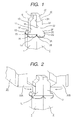
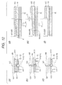
- Fig. 1 is an enlarged perspective view showing a connection between electric wires (joint conductors) to which the present invention is applied.
- Electric wires (joint conductors) 1 and 2 respectively comprise conductors 1A and 2A of a rectangular section coated and insulated with enamel coatings 1B and 2B.
- the enamel coatings 1B and 2B are chipped off at tips of the electric wires (joint conductors) 1 and 2 to form, at the tips, projecting portions 1C and 2C which are the smallest in sectional area.
- the small projecting portions 1C and 2C function as cutting portions when cutting a single long conductor (a detailed description will be given later) to form a conductor piece of a required length.
- Sectional area portions of a medium size, which function as welding portions 1D and 2D are formed between the small projecting portions 1C, 2C and the enamel coatings 1B, 2B.
- One sides between the small projecting portions 1C, 2C and the welding portions 1D, 2D are connected together through first slant faces 1E and 2E having outward inclinations toward the enamel coatings 1B and 2B.
- the welding face portions 1D, 2D and the enamel coatings 1B, 2B are connected together through stepped portions 1F and 2F.
- second slant faces 1G and 2G having outward inclinations toward the enamel coatings 1B and 2B are formed between the stepped portions 1F, 2F and the enamel coatings 1B, 2B.
- the sides of the electric wires (joint conductors) 1 and 2 opposite to the side including the first slant faces 1E, 2E, and the stepped portions 1F, 2F are formed flat from the enamel coatings 1B and 2B up to tips of the small projecting portions 1C and 2C.
- the tip portions of the joint conductors 1 and 2 are in close contact with each other.
- This construction is characteristic in that there is no gap between joined faces formed by the flat face portions 1H and 2H.
- the heat dissipating area of the joined face portions diminishes by about 25% and it becomes possible to effect joining to a satisfactory extent with a relatively small quantity of heat during welding. Coupled with a reduced quantity of heat because of a small sectional area of the tip portions of the conductors, it becomes possible to conduct heating more effectively.
- the remaining two faces at the tips of the electric wires (joint conductors) 1 and 2 are formed as flat faces 1J, 2J and flat faces (not shown) on the back sides.
- the enamel coatings 1B and 2B are chipped off to form third slant faces 1k and 2K which are inclined outwards toward the enamel coatings 1B and 2B. This is also true of the back faces.
- the first slant faces 1E, 2E, the second slant faces 1G, 2G, the third slant faces 1K, 2K, the flat faces 1J, 2J and their back faces are formed with edges of a cutter (to be described later) which chips off the coatings 1B and 2B of the conductors.
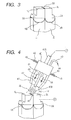
- Fig. 2 is a diagram explanatory of a process of cutting the joined face portions into a shape which facilitates welding.
- the tip portions of the electric wires (joint conductors) 1 and 2 are cut by operating cutting edges 20A and 20B of a cutter 20 in the directions of arrows in Fig. 2 at intermediate positions (shown in Fig. 2 ) of the welding face portions 1D and 2D as portions of a medium sectional area.
- Fig. 3 shows a welded state of both conductors by Tig welding (Tungsten Inert Gas welding) on the cut faces.
- Fig. 4 illustrates in what manner the joined face portions are Tig-welded.
- a heat-resistant tungsten electrode 42 is held in a collet 41 of a torch 40 and an inert gas (argon or helium gas) 44 is introduced through a gas introducing pipe 43 around the tungsten electrode 42 and is ejected through a gas nozzle 47 to around a welding portion.
- a jet 48 of the inert gas cuts off the welding portion from air, creating an oxygen-free state. As a result, the material is difficult to be oxidized because there is no oxygen (air) in the welding portion.
- the electric wires (joint conductors) 1A and 2A are copper wires, they are used as positive electrodes, while an electrode 41A of the collet 41 is used as a negative electrode, and a DC voltage is applied, causing an arc 40B to be produced between the tungsten electrode 42 and the joined faces 1L, 2L of the electric wires (joint conductors) 1A, 2A.
- the temperature of the arc 40B reaches a temperature of 5000 to 30000 degrees. With the heat of the arc 40B, the joined face portion between the joined faces 1L and 2L is melted and welded.
- the stepped portions 1F and 2F act as receiving portions of molten metal spatter, whereby the possibility of the spatter adhering to for example of the face of the insulating film and impairing the insulating property can also be diminished.
- the electric wires (joint conductors) 1 and 2 are rectangular conductors whose section perpendicular to the longitudinal axis of each conductor is a rectangular section comprising long and short sides.
- the outer peripheries of the electric wires are coated for insulation with enamel coatings 1A and 2A.
- the machining method should be a method suitable for automation so that the enamel coating removing work and a cutting work for cutting the conductor into a specific length suitable for the purpose of use.
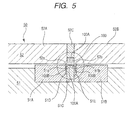
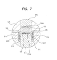
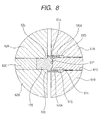
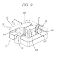
- Figs. 5 to 12 are drawings f or explaining the enamel coating removing work, of which Fig. 5 illustrates a process of chipping off the enamel coatings on short sides, Fig. 6 illustrates a process of chipping off the enamel coatings on long sides, Fig. 7 is an enlarged diagram of a circular frame portion in Fig. 5 , Fig. 8 is an enlarged diagram of a circular frame portion in Fig. 6 , and Fig. 9 is an appearance diagram of a chip-off device.
- Chip-off devices 50 and 60 comprise fixed dies 51, 61 and movable dies 52, 62.
- the fixed dies 51 and 61 comprise a pair of fixed clamping fixtures 51A, 51B and a pair of fixed clamping fixtures 61A, 61B, respectively, and centrally provided, combined conductor guides and fixed blades 51C and 61C, respectively.
- the movable dies 52 and 62 comprise a pair of movable cutting blades 52A, 52B and a pair of movable cutting blades 62A, 62B, respectively, and centrally provided, conductor pressers 52C and 62C, respectively.
- the combined conductor guides and fixed cutting blades 51C, 61C and the movables cutting blades 52A, 52B, 62A, 62B have respective edges 51a, 51b, 61a, 61b, 52a, 52b, 62a, and 62b.
- the chip-off devices 50 and 60 are installed side by side before and after a machining line.
- An enamel coating 100A on each short side is first excised and this excised portion is fed to the position of the chip-off device 60, where the enamel coating 100A on each long side is chipped off.
- enamel coating 100A-chipped off portions are formed continuously at certain intervals on the long conductor.
- conductor feed guides 101 and 102 for feeding straight an insulated conductor.
- An insulated conductor 100 which has been fed over a certain length by means of a feeder (not shown) is guided into a groove 51F in such a manner that long sides of the conductor 100 come into abutment against the slot, the groove 51F being formed in an end face of the combined conductor guide and fixed cutting blade 51C in the chip-off device 50.
- the insulated conductor 100 is pressed down in the direction of the combined conductor guide and fixed cutting blade 51C by means of the conductor presser 52C which is disposed at a position confronting the combined conductor guide and fixed cutting blade 51C, whereby the position of the insulated conductor 100 is fixed (see Figs. 10A and 10C ).
- the movable blades 52A and 52B move from above to below in the drawings, with the result that a shear force is developed between the edges 52a, 52b of the movable cutting blades 52A, 52B and the edges 51a, 51b of the combined conductor guide and fixed cutting blade 51C.
- the drawings illustrate a state in which the coating is being chipped off with the shear force.
- the chipped-off coating and a part of the conductor (chips resulting from cutting) are held in gaps 51D and 51E formed between the fixed clamping fixtures 51A, 51B and the combined conductor guide and fixed cutting blade 51C (see Figs. 10B and 10D ).
- the insulated conductor 100 is fed to the position of the next chip-off device 60 by means of a feeder (not shown) .
- Fig. 11 shows an appearance of the insulated conductor upon completion of chipping-off of the short-side enamel coating 100A.
- the same constituent portions as in Fig. 1 are identified by the same reference numerals as in Fig. 1 .
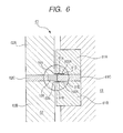
- the chip-off device 60 is disposed at a position corresponding to a 90°-rotated position of the chip-off device 50.
- the movable cutting blades 62A and 62B of the chip-off device 60 are disposed on the same machining line so as to reciprocate perpendicularly to the movable cutting blades 52A and 52B of the chip-off device 50.
- the chip-off device 60 is also provided with conductor feed guides 101 and 102 at an inlet and an outlet, respectively, for feeding the insulated conductor straight.
- the enamel coating 100A-chipped off portion on a short side of the insulated conductor 100 which has been fed a certain length by the feeder (not shown) is set to the position of a groove 61F which is formed in an end face of the combined conductor guide and fixed cutting blade 61C of the chip-off device 60. In this state a gap is still present between the face of the chipped-off portion and the face of the groove 61F (see Figs. 12A and 12D ).
- Figs. 6 and 8 show an interim state. Before reaching the state shown in Figs. 6 and 8 , first the movable blades 62A and 62B move from right to left in the figures, with the result that the edges 62a and 62b of the movable cutting blades 62A and 62B come into abutment against the to-be-chipped off portion of the insulated conductor 100. As shown in Figs.
- the edges 62a and 62b of the movable cutting blades 62A and 62B are formed axially longer than the edges 52a and 52b of the movable cutting blades 52A and 52B, so that the insulated conductor can be chipped off over a longer axial portion than the portion which has been cut with the edges 52a and 52b of the movable cutting blades 52A and 52B in the previous process. Consequently, it is possible to solve the problem that the conductor is torn off in the portion of a small sectional area previously chipped off when the edges 62a and 62b of the movable cutting blades 62A and 62B come into abutment against only the said potion of a small sectional area.
- the edges 62a and 62b of the movable cutting blades 62A and 62b move toward the combined conductor guide and fixed cutting blade 61C, the long-side portions with the sectional area not reduced yet begin to be chipped off by the edges 62a and 62b.
- the pressing force of the movable cutting blades 62A and 62B is borne by abutment of an outer face of the axially outer portion of a larger sectional area with respect to the portion chipped off previously by the edges 52a and 52b of the movable cutting blades 52A and 52B against the fixed clamping fixtures 61A and 61B (see Figs. 12B and 12E ).
- edges 62a and 62b move toward the combined conductor guide and fixed cutting blade 61C, the edges 62a and 62b reach the face of the portion of a smaller sectional area which was chipped off with the edges 52a and 52b of the movable cutting blades 52A and 52B in the previous process.
- the portion chipped off in the previous process and reduced in sectional area undergoes the pressing force of the conductor presser 62C and that of the movable cutting blades 62A, 62B and is deformed leftwards in the drawings. This deformation continues until the groove 61F-side face of the portion reduced in sectional area is pressed against the bottom face of the groove 61F (see Figs. 12C and 12F ).
- the conductor is excised with a shear force developed between the edges 62a, 62b of the movable cutting blades 62A, 62B and the edges 61a, 61b of the combined conductor guide and fixed cutting blade 61C.
- Figs. 6 and 8 show an interim state, in which the chipped-off coating and a part of the conductor (chips resulting from cutting) are held in gaps 61D and 61E formed between the fixed clamping fixtures 61A, 61B and the combined conductor guide and fixed cutting blade 61C.
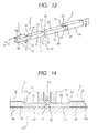
- Fig. 13 shows the insulated conductor 100 after chipping-off of the short- and long-side enamel coatings.
- the reference numerals described in Fig. 13 are the same as those used for the electric wires (joint conductors) 1 and 2 in Fig. 1 , indicating the same portions as in Fig. 1 .
- the pair of electric wires (joint conductors) 1 and 2 assume a state in which both are connected together through the projecting portion 1C.
- the portion of the smallest sectional area is formed by central edge portions of the edges 52a and 52b of the movable cutting blades 52A and 52B when the short-side coating is chipped off.
- the size of a short side is L1 and that of a long side is L2, both being in the relation of L1 ⁇ L2.
- a cutting device is disposed at a position just behind the chip-off device 60 on the machining line. When the chipping-off is completed by the chip-off device 60 , the electric wires are fed up to the position of the cutting device.
- Fig. 14 is a sectional view taken along line P-P in Fig. 13 , showing a state in which the insulated conductors are set to the cutting device.
- the cutting device includes a cutting blade 110 and cut assisting fixtures 111 disposed on both sides of the cutting blade 110.
- the cut assisting fixtures 111 function not only as guides for the cutting blade 110 but also as holding fixtures for holding the conductors firmly.
- the cutting blade 110 is moved toward the receiving die 112, whereby the portion of the smallest section is cut to form a projecting portion 1C.
- the faces of the electric wires (joint conductors) 1 and 2 which faces are in contact with the receiving die 112 form joined faces 1H and 2H after the cutting.
- the joined faces 1H and 2H are deformed (offset to one side from the center) so as to be flush (coplanar) with the faces of the enamel coatings 1B and 2B.
- the enamel coating-chipped off portions are thus deformed (offset to one side from the center) simultaneously with the chipping-off of the long-side enamel coating
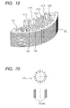
- Fig. 16 illustrates coil conductors in a stator of a rotary electric machine which is provided with the electric wires (joint conductors) shown in Figs. 1 , 13 and 14 .
- the coil conductors which constitute a stator in the rotary electric machine, are an inner coil 131 inserted inside a slot of the stator, an outer coil 133 inserted outside the slot, and a crossover coil 132 which provides a connection between the inner and outer coils.
- Enamel coating-chipped off portions 131A, 131B, 132A, 132B, 133A, and 133B of the shape described above are formed at both ends of the coil conductors by the above process.
- Each coil conductor is bent nearly centrally, as shown in Fig. 17 . A description on the bending process will be described later.
- the inner and outer coils 131, 133 are each formed in a generally hexagonal shape. Twisted portions 131C, 133C and slant side portions 131G, 131F, 133G, 133F form crossover line portions of stator coils.
- predetermined joined face portions are joined together at their joined faces, then are cut as in Fig. 2 , and thereafter welded as in Figs. 3 and 4 .
- stator coils are inserted into slots 161 of the stator indicated at 160, as shown in Fig. 19 and are joined by welding in the respective joined face portions to form stator coils.
- the coil conductors shown in Fig. 16 which serve as base metals of the inner and outer coils 131, 133 are formed in U shape in a U shape forming process (not shown), then in the process shown in Fig. 20 , plural U-shaped inner and outer coils 131, 133 are inserted and set into separate inserting fixtures 200.
- a stator core 302 is set in a stator assembly fixture 300 provided with a coil guide 301.
- the inner coils 131 are first set using the coil guide 301 into slots formed in the stator core 302 which has been set in the stator assembling fixture 300.
- the outer coils 133 are inserted and set into slots formed in the stator core 302 with use of the coil guide 301 so as to be positioned outside the inner coils 131 which have already been set.
- Fig. 25 shows the stator core 302 with inner and outer coils 131, 133 set therein.
- the outer coils 133 are first pushed into the stator 302 with use of a coil pushing jig 303 and a rotary shaft 304 is rotated in e direction of arrow, causing a lower die 305 to rotate and thereby twisting the joining end portions into a predetermined shape.
- the lower die 305 is removed and terminals of the outer coils 133 are deformed into a state necessary for joining as in Fig. 1 , followed by caulking to effect forming. Thereafter, cutting is performed by the cutting device as in Fig. 2 and preparations are made for welding.
- the joined face portions are welded by Tig welding by the method shown in Figs. 3 and 4 .
- a welding height is measured by a sensor 306 and a check is made to see whether the measured height is an appropriate height or not.
- the inner coils 131 are pushed into the stator 302 with use of a coil pushing jig 307 and the rotary shaft 304 is rotated in the direction of arrow to rotate the lower die 305, thereby twisting the joining end portions into a predetermined shape.
- the lower die 305 is removed and terminals of the inner coils 131 are deformed into a state necessary for joining as in Fig. 1 , followed by caulking to effect forming. Thereafter, cutting is performed by the cutting device as in Fig. 2 and preparations are made for welding.
- the joined face portions are welded by Tig welding by the method shown in Figs. 3 and 4 .
- a welding height is measured by the sensor 306 and a check is made to see whether the measured height is an appropriate height or not.
Landscapes
- Engineering & Computer Science (AREA)
- Power Engineering (AREA)
- Manufacturing & Machinery (AREA)
- Manufacture Of Motors, Generators (AREA)
- Windings For Motors And Generators (AREA)
- Insulation, Fastening Of Motor, Generator Windings (AREA)
Abstract
Joint Structure of Electric Wire, Stator of Rotary Electric Machine, Method for Manufacturing the same
When electric wires (joint conductors) are disposed adjacent each other in a peeled state of coatings, a gap corresponding to the total thickness of both conductors' insulating films as skin layers is formed between end joined face portions 1H, 2H of the conductors. The gap becomes larger because the conductors are tapered. Therefore, the adhesion between both conductors is impaired, with a consequent fear of occurrence of joining imperfection. In opposed joined face portions 1H, 2H of electric wires (joint conductors), the conductors are deformed from the tips of their axes to the joined face side in such a manner that exposed portions 1A, 2A at the tips of the conductors and insulating film faces located in the vicinity thereof are flush with each other or the exposed portions 1A, 2B are projected. The gap formed between the electric wires (joint conductors) can be diminished, whereby the reliability of connection is improved and it becomes easier to perform the work of joint conductors, with the result that the productivity of a stator 160 of a rotary electric machine such as an AC generator for a vehicle could be improved.
When electric wires (joint conductors) are disposed adjacent each other in a peeled state of coatings, a gap corresponding to the total thickness of both conductors' insulating films as skin layers is formed between end joined face portions 1H, 2H of the conductors. The gap becomes larger because the conductors are tapered. Therefore, the adhesion between both conductors is impaired, with a consequent fear of occurrence of joining imperfection. In opposed joined face portions 1H, 2H of electric wires (joint conductors), the conductors are deformed from the tips of their axes to the joined face side in such a manner that exposed portions 1A, 2A at the tips of the conductors and insulating film faces located in the vicinity thereof are flush with each other or the exposed portions 1A, 2B are projected. The gap formed between the electric wires (joint conductors) can be diminished, whereby the reliability of connection is improved and it becomes easier to perform the work of joint conductors, with the result that the productivity of a stator 160 of a rotary electric machine such as an AC generator for a vehicle could be improved.
Description
- The present invention relates to a stator of a rotary electric machine such as, for example, an AC generator for a vehicle and a method for manufacturing the same, as well as a joint structure of electric wires and a method for manufacturing the same.
- According to a known electric wire, an end portion of an electric wire (a joint conductor) which end portion extends over a predetermined range from a tip of the wire is plastically deformed so that a sectional area thereof becomes smaller than that of a main portion of the conductor, and the wire is constructed so that the main portion and a part of the end portion near the main portion are coated uniformly with an insulating film, then two such electric wires (joint conductors) are joined together in a matched state of respective end portions.
- Japanese Patent Laid-Open Publication No.
2002-95198 - In the above conventional technique, since the sectional area of the end portion is decreased while preventing damage of the insulating film, a heat input quantity can be decreased. Consequently, there is no fear that an insulating material located near a joined portion may be deteriorated with heat produced a joining work, and hence the insulating performance is not impaired.
- In the above conventional technique, however, if two electric wires (joint conductors) are positioned adjacent each other in a peeled state of respective insulating coatings, there is formed a gap with corresponding to the total thickness of both conductor's insulating coatings as skin layers in a joined face portion between end portions of the conductors. The gap becomes larger because the conductors are tapered at their tips. Therefore, the adhesion between both conductors is impaired, with a consequent fear of occurrence of joining imperfection.
- It is an object of the present invention to minimize the gap developed between electric wires (joint conductors), thereby improving the reliability of joining, and facilitate the conductor joining work, thereby improving the productivity of a state of a rotary electric machine such as, for example, an AC generator for a vehicle.
- The present invention provides an electric wire joint structure comprising:
- insulator-coated wires each having a portion where an insulator coating is removed to expose the conductor.
- The exposed portions of the conductors maybe opposed to each other to form joining faces. The joining faces of the exposed portions may be flush with the surfaces of the insulator coatings of the insulator-coated wires or may be projecting from the surfaces of the insulator coatings of the insulator-coated wires. Further, the joining faces are joined, preferably metallurgically.
- According to one aspect of the present invention, for achieving the above-mentioned object, in opposed joined face portions of electric wires (joint conductors) the axes of the conductors' exposed portions may be offset relative to the axes of the insulating coating in such a manner that exposed tip portions of the conductors and insulating coating faces located in the vicinity thereof are flush with each other or the conductors' exposed portions are projected.
- According to another aspect of the present invention constructed as above, since joined faces of the joined face portions at the tips of the conductors with insulating coatings removed confront each other, it is not necessary to keep the two pushed against each other with a strong force during the joining work. Besides, it is possible to diminish the likelihood of peeling-off of the joined face portion caused by spring-back after joining. As a result, not only the rationalization of the joining work can be attained, but also the reliability of the joined state of the joined face portion is improved and so are the productivity and reliability of, for example, the stator of a rotary electric machine.
-
-
Fig. 1 is an enlarged perspective view showing a connection between electric wires (joint conductors) to which the present invention is applied; -
Fig. 2 is a diagram illustrating a process of cutting joined face portions into a shape easy to weld; -
Fig. 3 is a diagram showing a welded state of the joined face portions; -
Fig. 4 is a diagram for explaining in what state the joined face portions are Tig-welded; -
Fig. 5 is a diagram showing a process of chipping off enamel coatings on short sides; -
Fig. 6 is a diagram showing a process of chipping off enamel coatings on long sides; -
Fig. 7 is an enlarged diagram of a circular frame portion inFig. 5 ; -
Fig. 8 is an enlarged diagram of a circular frame portion inFig. 6 ; -
Fig. 9 is an appearance diagram of a chip-off device; -
Figs. 10A to 10D are diagrams for explaining a process of chipping off enamel coatings on shorts sides; -
Fig. 10 is a perspective view showing insulated conductors after chipping-off of the short-side enamel coatings; -
Figs. 12A to 12F are diagrams for explaining a process of chipping off enamel coatings on long sides; -
Fig. 13 is a perspective view showing the insulated conductorsafterchipping-off of the short- and long-side enamel coatings; -
Fig. 14 is a diagram showing a state in which the insulated conductors after chipping-off of the short- and long-side enamel coatings have been set to a cutting device; -
Fig. 15 is a diagram for explaining another machining method; -
Fig. 16 is a diagram showing base metals of coil conductors used in a stator of a rotary electric machine; -
Fig. 17 is a diagram showing bent coil conductors; -
Fig. 18 is a diagram showing an inner coil and an outer coil each formed in the hexagonal shape; -
Fig. 19 is a diagram showing a part of a stator of a rotary electric machine according to the present invention; -
Fig. 20 is a diagram for explaining a process to be carried out prior to a stator assembling process; -
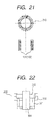
Fig. 21 is a diagram for explaining another process to be carried out prior to the stator assembling process; -
Fig. 22 is a diagram for explaining a state in which a stator core has been set to a stator assembling fixture; -
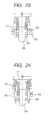
Fig. 23 is a diagram for explaining in which state inner coils are set to the stator core; -
Fig. 24 is a diagram for explaining in which state outer coils are set to the stator core; -
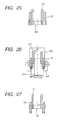
Fig. 25 is a diagram showing the stator core with inner and outer coils set thereto; -
Fig. 26 is a diagram for explaining a process of twisting the outer coils; -
Fig. 27 is a diagram for explaining a process of deforming and caulking the outer coils into a state necessary for joining; -
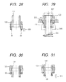
Fig. 28 is a diagram for explaining a process of welding joined face portions of the outer coils; -
Fig. 29 is a diagram for explaining a process of twisting the inner coils; -
Fig. 30 is a diagram for explaining a process of deforming and caulking the inner coils into a state necessary for joining; and -
Fig. 31 is a diagram for explaining a process of welding joined face portions of the inner coils. - Embodiments of the present invention will be described hereinunder with reference to the drawings.
-
Fig. 1 is an enlarged perspective view showing a connection between electric wires (joint conductors) to which the present invention is applied. - Electric wires (joint conductors) 1 and 2 respectively comprise
conductors enamel coatings - The
enamel coatings portions portions welding portions portions enamel coatings portions welding portions first slant faces enamel coatings - The
welding face portions enamel coatings stepped portions - Further, second slant faces 1G and 2G having outward inclinations toward the
enamel coatings portions enamel coatings - The sides of the electric wires (joint conductors) 1 and 2 opposite to the side including the first slant faces 1E, 2E, and the stepped
portions enamel coatings portions - At the flat face portions, indicated at 1H and 2H, the tip portions of the
joint conductors - This construction is characteristic in that there is no gap between joined faces formed by the
flat face portions - The remaining two faces at the tips of the electric wires (joint conductors) 1 and 2 are formed as
flat faces - Also on the flat faces 1J and 2J the
enamel coatings enamel coatings - The first slant faces 1E, 2E, the second slant faces 1G, 2G, the third slant faces 1K, 2K, the flat faces 1J, 2J and their back faces are formed with edges of a cutter (to be described later) which chips off the
coatings -
Fig. 2 is a diagram explanatory of a process of cutting the joined face portions into a shape which facilitates welding. - Before welding, the tip portions of the electric wires (joint conductors) 1 and 2 are cut by operating
cutting edges cutter 20 in the directions of arrows inFig. 2 at intermediate positions (shown inFig. 2 ) of thewelding face portions -
Fig. 3 shows a welded state of both conductors by Tig welding (Tungsten Inert Gas welding) on the cut faces. -
Fig. 4 illustrates in what manner the joined face portions are Tig-welded. - By welding the cut faces, indicated at 1L and 2L, by Tig welding (Tungsten Inert Gas welding), the joined faces of the electric wires (joint conductors) 1A and 2A are joined together by molten
metal 30. - More specifically, a heat-
resistant tungsten electrode 42 is held in acollet 41 of atorch 40 and an inert gas (argon or helium gas) 44 is introduced through agas introducing pipe 43 around thetungsten electrode 42 and is ejected through agas nozzle 47 to around a welding portion. Ajet 48 of the inert gas cuts off the welding portion from air, creating an oxygen-free state. As a result, the material is difficult to be oxidized because there is no oxygen (air) in the welding portion. Since the electric wires (joint conductors) 1A and 2A are copper wires, they are used as positive electrodes, while anelectrode 41A of thecollet 41 is used as a negative electrode, and a DC voltage is applied, causing anarc 40B to be produced between thetungsten electrode 42 and the joined faces 1L, 2L of the electric wires (joint conductors) 1A, 2A. In this welding, the temperature of thearc 40B reaches a temperature of 5000 to 30000 degrees. With the heat of thearc 40B, the joined face portion between the joined faces 1L and 2L is melted and welded. - The smaller the heat dissipating area and the smaller the amount of heat dissipated, the earlier the temperature of the welding portion can be raised up to the metal melting temperature.
- Besides, since there is no gap between the joined faces, there is no sump of air (oxygen), and even if a negative pressure portion occurs in the welding portion by the flow of inert gas which is blown off against the welding portion, there is no fear of air (oxygen) being introduced (flowing reverse) into the joined face portion and the welding portion is so much difficult to be oxidized, because in the welding portion there is not such a gap as serves as an air introducing passage.
- Since the joined faces are in close contact with each other, it is not necessary push the joined faces with a strong force from the exterior during welding. The problem that the joined portion springs back (a phenomenon that the joined portion repulses the pushing force and tends to revert to the original separated state) after welding, causing separation of the welded portion, is also solved. Further, it is not necessary to retain the pushing force until the joined portion gets cold for the prevention of separation caused by such a spring-back phenomenon, and the time required for the joining can so much be shortened.
- When the electric wires (joint conductors) are joined in a stand-up state, the stepped
portions - Now, with reference to
Figs. 5 and6 , a description will be given below about a method and apparatus for manufacturing the electric wires (joint conductors) 1 and 2 described above. - As also described earlier, the electric wires (joint conductors) 1 and 2 according to this embodiment are rectangular conductors whose section perpendicular to the longitudinal axis of each conductor is a rectangular section comprising long and short sides. The outer peripheries of the electric wires are coated for insulation with
enamel coatings - In case of welding an end portion of a conductor to another conductor, the enamel coating thereof becomes an obstacle. Therefore, it is necessary to remove the enamel coating on the end portion of each conductor which portion serves as a conductor joined face portion to facilitate welding. Besides, the machining method should be a method suitable for automation so that the enamel coating removing work and a cutting work for cutting the conductor into a specific length suitable for the purpose of use.
-
Figs. 5 to 12 are drawings f or explaining the enamel coating removing work, of whichFig. 5 illustrates a process of chipping off the enamel coatings on short sides,Fig. 6 illustrates a process of chipping off the enamel coatings on long sides,Fig. 7 is an enlarged diagram of a circular frame portion inFig. 5 ,Fig. 8 is an enlarged diagram of a circular frame portion inFig. 6 , andFig. 9 is an appearance diagram of a chip-off device. - Chip-off
devices - The fixed dies 51 and 61 comprise a pair of fixed
clamping fixtures clamping fixtures blades - The movable dies 52 and 62 comprise a pair of
movable cutting blades movable cutting blades conductor pressers - The combined conductor guides and fixed
cutting blades movables cutting blades respective edges - The chip-
off devices enamel coating 100A on each short side is first excised and this excised portion is fed to the position of the chip-off device 60, where theenamel coating 100A on each long side is chipped off. In thisway enamel coating 100A-chipped off portions are formed continuously at certain intervals on the long conductor. - As shown in
Fig. 9 , at an inlet and an outlet of the chip-off device 50 there are provided conductor feed guides 101 and 102, respectively, for feeding straight an insulated conductor. Aninsulated conductor 100 which has been fed over a certain length by means of a feeder (not shown) is guided into agroove 51F in such a manner that long sides of theconductor 100 come into abutment against the slot, thegroove 51F being formed in an end face of the combined conductor guide and fixedcutting blade 51C in the chip-off device 50. - As shown in
Figs. 5 ,7 and10 , theinsulated conductor 100 is pressed down in the direction of the combined conductor guide and fixedcutting blade 51C by means of theconductor presser 52C which is disposed at a position confronting the combined conductor guide and fixedcutting blade 51C, whereby the position of theinsulated conductor 100 is fixed (seeFigs. 10A and 10C ). - Next, the
movable blades edges movable cutting blades edges cutting blade 51C. The drawings illustrate a state in which the coating is being chipped off with the shear force. The chipped-off coating and a part of the conductor (chips resulting from cutting) are held ingaps fixed clamping fixtures cutting blade 51C (seeFigs. 10B and 10D ). - When the chipping-off of the
enamel coating 100A on short sides is over, theinsulated conductor 100 is fed to the position of the next chip-off device 60 by means of a feeder (not shown) . -
Fig. 11 shows an appearance of the insulated conductor upon completion of chipping-off of the short-side enamel coating 100A. The same constituent portions as inFig. 1 are identified by the same reference numerals as inFig. 1 . - The chip-
off device 60 is disposed at a position corresponding to a 90°-rotated position of the chip-off device 50. Themovable cutting blades off device 60 are disposed on the same machining line so as to reciprocate perpendicularly to themovable cutting blades off device 50. - Like the device shown in
Fig. 9 , the chip-off device 60 is also provided with conductor feed guides 101 and 102 at an inlet and an outlet, respectively, for feeding the insulated conductor straight. Theenamel coating 100A-chipped off portion on a short side of theinsulated conductor 100 which has been fed a certain length by the feeder (not shown) is set to the position of agroove 61F which is formed in an end face of the combined conductor guide and fixedcutting blade 61C of the chip-off device 60. In this state a gap is still present between the face of the chipped-off portion and the face of thegroove 61F (seeFigs. 12A and 12D ). -
Figs. 6 and8 show an interim state. Before reaching the state shown inFigs. 6 and8 , first themovable blades edges movable cutting blades insulated conductor 100. As shown inFigs. 12B and 12E , theedges movable cutting blades edges movable cutting blades edges movable cutting blades edges movable cutting blades - Further, as the
edges movable cutting blades cutting blade 61C, the long-side portions with the sectional area not reduced yet begin to be chipped off by theedges movable cutting blades edges movable cutting blades clamping fixtures Figs. 12B and 12E ). - Then, as the
edges cutting blade 61C, theedges edges movable cutting blades conductor presser 62C and that of themovable cutting blades groove 61F-side face of the portion reduced in sectional area is pressed against the bottom face of thegroove 61F (seeFigs. 12C and 12F ). - After abutment of the
groove 61F - side face of the portion reduced in sectional area against the bottom face of thegroove 61F, the conductor is excised with a shear force developed between theedges movable cutting blades edges cutting blade 61C. -
Figs. 6 and8 show an interim state, in which the chipped-off coating and a part of the conductor (chips resulting from cutting) are held ingaps fixed clamping fixtures cutting blade 61C. - In
Fig. 9 , the fixed and movable dies 51, 52 and cutting blades are positioned by positioningpins -
Fig. 13 shows theinsulated conductor 100 after chipping-off of the short- and long-side enamel coatings. The reference numerals described inFig. 13 are the same as those used for the electric wires (joint conductors) 1 and 2 inFig. 1 , indicating the same portions as inFig. 1 . - After the enamel coatings have been chipped off by the excising
devices portion 1C. - The portion of the smallest sectional area is formed by central edge portions of the
edges movable cutting blades Fig. 13 , the size of a short side is L1 and that of a long side is L2, both being in the relation of L1<L2. - A cutting device is disposed at a position just behind the chip-
off device 60 on the machining line. When the chipping-off is completed by the chip-off device 60 , the electric wires are fed up to the position of the cutting device. -
Fig. 14 is a sectional view taken along line P-P inFig. 13 , showing a state in which the insulated conductors are set to the cutting device. - As shown in
Fig. 14 , the cutting device includes acutting blade 110 and cut assistingfixtures 111 disposed on both sides of thecutting blade 110. Thecut assisting fixtures 111 function not only as guides for thecutting blade 110 but also as holding fixtures for holding the conductors firmly. In a state in which the conductors are pressed against a receivingdie 112 by the cut assisting clampingfixtures 111, thecutting blade 110 is moved toward the receivingdie 112, whereby the portion of the smallest section is cut to form a projectingportion 1C. - At this time, the faces of the electric wires (joint conductors) 1 and 2 which faces are in contact with the receiving die 112 form joined faces 1H and 2H after the cutting. As shown clearly in
Fig. 14 , the joined faces 1H and 2H are deformed (offset to one side from the center) so as to be flush (coplanar) with the faces of theenamel coatings - Although in the above embodiment the enamel coating-chipped off portions are thus deformed (offset to one side from the center) simultaneously with the chipping-off of the long-side enamel coating, there may be adopted a method wherein the portions in question are not deformed (offset to one side from the center), but are pressed and deformed longitudinally as indicated with broken lines by pressing
fixtures Fig. 15 , followed by cutting of the portion of the smallest section with use of thecutting blade 110. -
Fig. 16 illustrates coil conductors in a stator of a rotary electric machine which is provided with the electric wires (joint conductors) shown inFigs. 1 ,13 and 14 . - The coil conductors, which constitute a stator in the rotary electric machine, are an
inner coil 131 inserted inside a slot of the stator, anouter coil 133 inserted outside the slot, and acrossover coil 132 which provides a connection between the inner and outer coils. - Enamel coating-chipped off
portions - Each coil conductor is bent nearly centrally, as shown in
Fig. 17 . A description on the bending process will be described later. - As shown in
Fig. 18 , the inner andouter coils Twisted portions 131C, 133C andslant side portions - In the enamel coating-chipped off
portions Fig. 2 , and thereafter welded as inFigs. 3 and 4 . - The coils thus formed are inserted into
slots 161 of the stator indicated at 160, as shown inFig. 19 and are joined by welding in the respective joined face portions to form stator coils. - Next, a process of forming the stator coils 131, 133 and a process of assembling the
stator 160 will be described below with reference toFigs. 20 to 31 . - The coil conductors shown in
Fig. 16 which serve as base metals of the inner andouter coils Fig. 20 , plural U-shaped inner andouter coils fixtures 200. - In the process shown in
Fig. 21 , the U-shaped portions of the plural inner andouter coils fixtures 200 are twisted by twistingfixtures 210. - In the process shown in
Fig. 22 , astator core 302 is set in astator assembly fixture 300 provided with acoil guide 301. - In the process shown in
Fig. 23 , theinner coils 131 are first set using thecoil guide 301 into slots formed in thestator core 302 which has been set in thestator assembling fixture 300. - In the process shown in
Fig. 24 , theouter coils 133 are inserted and set into slots formed in thestator core 302 with use of thecoil guide 301 so as to be positioned outside theinner coils 131 which have already been set. -
Fig. 25 shows thestator core 302 with inner andouter coils - In this state, joined end portions of the inner and
outer coils - In the process shown in
Fig. 26 , theouter coils 133 are first pushed into thestator 302 with use of acoil pushing jig 303 and arotary shaft 304 is rotated in e direction of arrow, causing alower die 305 to rotate and thereby twisting the joining end portions into a predetermined shape. - In the process shown in
Fig. 27 , thelower die 305 is removed and terminals of theouter coils 133 are deformed into a state necessary for joining as inFig. 1 , followed by caulking to effect forming. Thereafter, cutting is performed by the cutting device as inFig. 2 and preparations are made for welding. - In the process shown in
Fig. 28 , the joined face portions are welded by Tig welding by the method shown inFigs. 3 and 4 . At this time, a welding height is measured by asensor 306 and a check is made to see whether the measured height is an appropriate height or not. - In the process shown in
Fig. 29 , theinner coils 131 are pushed into thestator 302 with use of acoil pushing jig 307 and therotary shaft 304 is rotated in the direction of arrow to rotate thelower die 305, thereby twisting the joining end portions into a predetermined shape. - In the process shown in
Fig. 30 , thelower die 305 is removed and terminals of theinner coils 131 are deformed into a state necessary for joining as inFig. 1 , followed by caulking to effect forming. Thereafter, cutting is performed by the cutting device as inFig. 2 and preparations are made for welding. - In the process shown in
Fig. 31 , the joined face portions are welded by Tig welding by the method shown inFigs. 3 and 4 . At this time, a welding height is measured by thesensor 306 and a check is made to see whether the measured height is an appropriate height or not. - In this way the stator shown in
Fig. 19 is obtained. - According to the invention, there may be provided electric wire joint structures, stators, methods and apparatuses according to one or more of the following clauses:
- 1. An electric wire joint structure comprising:
- insulator-coated wires (1, 2) each having a portion (1A, 2A) where an insulator coating (18, 28) is removed to expose the conductor,
- 2. The electric wire according to
clause 1, wherein a sectional area of the conductor in the joined face portion (1H, 2H) of the exposed portion is smaller than that of the insulator-coated portion. - 3. The electric wire according to at least one of the preceding clauses, wherein a peripheral face in the joined face portion (1H, 2H) of the expose portion is a sheared plane.
- 4. The electric wire according to at least one of the preceding clauses wherein the conductor in the joined face portion (1H, 2H) of the exposed portion has a rectangular section.
- 5. The electric wire according to at least one of the preceding clauses, wherein the conductor in the insulator-coated portion has a rectangular section.
- 6. The electric wire according to at least one of the preceding clauses, wherein the conductor in the insulator-coated portion has a circular section.
- 7. The electric wire according to at least one of the preceding clauses, wherein a slant face (1K, 2K), which becomes thinker toward the exposed portion (1A, 2A) is formed between the conductor in the insulator-coated portion and the conductor in the exposed portion.
- 8. The electric wire according to at least one of the preceding clauses, wherein the section of the conductor in the joined face portion (1H, 2H) has a rectangular shape comprising long sides and short sides, and the conductor in the joined face portion (1H, 2H) is off set along the long sides toward the mating member to which it is to be joined.
- 9. The electric wire according to at least one of the preceding clauses, wherein a slant face (1K, 2K) which becomes thinner toward the exposed conductor portion (1A, 2A) is formed between the conductor in the insulator-coated portion and the conductor in the exposed conductor portion (1A, 2A), the section of the conductor in the joined face portion (1H, 2H) has a rectangular shape comprising long sides and short sides, and an outer end portion of the slant face (1K, 2K) on the long-sides side extends up to a position more distant from a tip of the exposed conductor portion than an outer end portion of the slant face (1G, 2G) on the short-sides side.
- 10. Astator (160) of a rotary electric machine with an electric wire wound thereon, comprising:
- the stator core (302) having a plurality of slots (161); and
- acoil (131, 133) comprising a plurality of linear members, each having an exposed portion (131A, 131B, 133A, 133B) of a conductor and an insulator-coated portion having an insulating coating on a surface of the conductor, the plural linear members being inserted into the slots (161), an axis of each of the exposed portions being offset relative to an axis of each of the insulator-coated portions, and the linear members being joined in joined face portions formed on offset-side faces.
- 11. A stator (160) of a rotary electric machine according to
clause 10, wherein the plural linear members inserted into the slots (161) are each formed in U shape having the joined face portions at both ends thereof. - 12. A stator (160) of a rotary electric machine according to at least one of the
clauses 10 to 11, wherein the plural linear members inserted into the slots (161) each comprise an axially short inner coil (131) and an axially long outer coil (133). - 13. A method for machining an electric wire, comprising:
- a pre-process of forming in part of an electric wire having an insulating coating (1B, 2B) a conductor-exposed portion (1A, 1B) of a rectangular section as a conductor portion resulting from chipping off of the insulating coating (1B, 2B),
- the pre-process comprising:
- a first insulating coating chipping-off step of forming a pair of exposed faces opposed to the conductor, and
- a second insulating coating chipping-off step of forming a pair of exposed faces on the outer periphery of the conductor not formed with exposed faces in he first insulating coating chipping-off step,
- the second insulating coating chipping-off step including a pressure forming step of pressing the conductor toward one of the exposed faces formed in the first insulating coating chipping-off step to displace an axis of the exposed portion of the conductor from an axis of the insulator-coated electric wire portion toward the one face by an amount substantially equal to the thickness chipped off in the first insulating coating chipping-off step; and
- a post-process of cutting an intermediate position of the conductor-exposed portion to form joined face portions (1H, 2H), the post-process being carried out after the pre-process.
- 14. A method for machining an electric wire according to clause 13, wherein an insulating coating (1B, 2B) chipping-off operation in a short sides direction of the section is carried out in the first insulating coating chipping-off step, an insulating coating chipping-off operation in a long sides direction of the section is carried out in the second insulating coating chipping-off step, and the pressure forming step is carried out simultaneously with or before or after the insulating coating chipping-off operation in the long sides direction.
- 15. A method for machining an electric wire according to at least one of the clauses 13 to 14, wherein a feed step of moving the electric wire by a specific length is carried out between the first and second insulating coating (1B, 2B) chipping-off steps in the pre-process.
- 16. A method for manufacturing a stator (160) of a rotary electric machine, the stator (160) comprising:
- a stator core (302) having a plurality of slots (161); and
- a coil (131, 133) comprising a plurality of linear members, the plural linear members each having an exposed portion (131A, 131B, 133A, 133B) of a conductor and an insulator-coated portion having an insulating coating on a surface of the conductor, the plural linear members being inserted into the slots (161), an axis of each of the exposed portions being offset relative to an axis of each of the insulator-coated portions, and the linear members being joined in joined face portions formed on offset-side faces, wherein
- the plural linear members inserted into the slots (161) are each formed in U shape having the joined face portions at both ends thereof;
- the plural linear members inserted into the slots (161) each constitute an axially short inner coil (131) and an axially long outer coil (133); and
- the joined face portions of the outer coil (133) are first joined and the joined face portions of the inner coil (131) is subsequently joined.
- 17. A method for manufacturing a stator (60) of a rotary electric machine according to clause 16, wherein after the outer coil (133) is pushed in up to a specific position and the associated joined face portions are joined, the inner coil (131) is pushed in up to the same specific position as that of the outer coil (133) and the associated joined face portions are joined.
- 18. A method for manufacturing a stator (160) of a rotary electric machine according to at least one of the clauses 16 to 17, comprising the step of cutting tips of the joined face portions of the inner and outer coils before the joining.
- 19. An apparatus for manufacturing an electric wire, comprising:
- a first receiving mold having a guide groove for guiding a conductor having an insulating coating;
- a first insulating coating chipping-off device (50) having a pair of first cutting teeth, the first cutting teeth being disposed in parallel and spaced a specific distance from each other and able to reciprocate relative to the first receiving mold;
- a second receiving mold disposed subsequent to the first insulating coating chipping-off device (50) and having a guide groove (51F)for guiding the conductor having the insulating coating; and
- a second insulating coating chipping-off device (60) having a pair of second cutting teeth, the second cutting teeth being disposed in parallel and spaced a specific distance from each other and able to reciprocate relative to the second receiving mold,
- the second insulating coating chipping-off device (60) having pressing means for pressing the conductor in the insulating coating chipping-off direction of the conductor to offset the conductor. 20. An apparatus for manufacturing an electric wire according to clause 19, wherein the second cutting teeth are longer than the first cutting teeth.
Claims (4)
- A stator for a rotary electric machine comprising a stator core having slots (161), and a group of unit coil conductors (1,2) which are inserted into the slots, wherein:stator coils are constituted by electrically connecting ends of the coil conductors (1,2),the unit coil conductors each has a rectangular transverse cross section at its tip, and four faces that delimit the rectangular cross section, andthe coil ends of said one end of the stator core are abutted and welded at tips of said welding portion.characterized in that:the adjoining two faces of the four faces of the portions where the insulating coating has been removed have different end positions of the removed insulating coating from each other.
- The stator according to claim 1, wherein a length from the tip end of the coil conductor on one side thereof to the end of the insulating coating is different from that from the tip of the coil conductor on the other side thereof.
- The stator according to claim 1 or 2, wherein the interface between the coil conductors (1, 2) along the longitudinal direction of the coil conductors is flat wherein the interface includes portions where the insulating coating in has been removed and not removed.
- The stator according to claim 1, 2 or 3, wherein a cross sectional area of the tip portion of the coil conductor where the insulating coating has been removed is smaller than that of the root portion where the insulating coating has been removed.
Applications Claiming Priority (2)
| Application Number | Priority Date | Filing Date | Title |
|---|---|---|---|
| JP2005150316A JP4654068B2 (en) | 2005-05-24 | 2005-05-24 | Bonded electric wire, method of processing the bonded electric wire, rotating electric machine stator, rotating electric machine stator manufacturing method, and bonded electric wire manufacturing apparatus |
| EP06010879A EP1727260B1 (en) | 2005-05-24 | 2006-05-24 | Joint structure of electric wire, stator of rotary electric machine, method for manufacturing the same |
Related Parent Applications (1)
| Application Number | Title | Priority Date | Filing Date |
|---|---|---|---|
| EP06010879.2 Division | 2006-05-24 |
Publications (1)
| Publication Number | Publication Date |
|---|---|
| EP2293416A2 true EP2293416A2 (en) | 2011-03-09 |
Family
ID=36739917
Family Applications (2)
| Application Number | Title | Priority Date | Filing Date |
|---|---|---|---|
| EP10185174A Withdrawn EP2293416A2 (en) | 2005-05-24 | 2006-05-24 | Joint structure of electric wire, stator of rotary electric machine, method for manufacturing the same |
| EP06010879A Ceased EP1727260B1 (en) | 2005-05-24 | 2006-05-24 | Joint structure of electric wire, stator of rotary electric machine, method for manufacturing the same |
Family Applications After (1)
| Application Number | Title | Priority Date | Filing Date |
|---|---|---|---|
| EP06010879A Ceased EP1727260B1 (en) | 2005-05-24 | 2006-05-24 | Joint structure of electric wire, stator of rotary electric machine, method for manufacturing the same |
Country Status (4)
| Country | Link |
|---|---|
| US (2) | US7615906B2 (en) |
| EP (2) | EP2293416A2 (en) |
| JP (1) | JP4654068B2 (en) |
| CN (2) | CN102594054B (en) |
Families Citing this family (50)
| Publication number | Priority date | Publication date | Assignee | Title |
|---|---|---|---|---|
| JP4412330B2 (en) | 2007-02-09 | 2010-02-10 | 株式会社デンソー | Stator winding of rotating electric machine and method of manufacturing the same |
| EP2245215A4 (en) * | 2009-02-10 | 2011-04-27 | Calera Corp | Low-voltage alkaline production using hydrogen and electrocatlytic electrodes |
| JP5586969B2 (en) | 2010-01-21 | 2014-09-10 | 株式会社デンソー | Rotating electric machine stator |
| IT1401829B1 (en) | 2010-09-29 | 2013-08-28 | Magneti Marelli Spa | ELECTRIC MACHINE PRESENTING A STATIC ROLL WITH RIGID BARS AND ITS CONSTRUCTION METHOD |
| IT1401831B1 (en) * | 2010-09-29 | 2013-08-28 | Magneti Marelli Spa | METHOD OF CONSTRUCTION OF AN ELECTRIC MACHINE PRESENTING A STATIC TAPE WITH A HARD BAR |
| JP5136920B2 (en) * | 2010-11-26 | 2013-02-06 | 株式会社デンソー | Rotating electrical machine stator for vehicles |
| CN101984543B (en) * | 2010-12-14 | 2012-11-28 | 南车株洲电机有限公司 | Insulating production process method of large alternating current machine stator core stretching screw |
| JP2012139075A (en) * | 2010-12-28 | 2012-07-19 | Hitachi Automotive Systems Ltd | Rotary electric machine |
| ITTO20110199A1 (en) * | 2011-03-07 | 2012-09-08 | Atop Spa | APPARATUS AND PROCEDURE FOR THE ALIGNMENT OF CONDUCTORS OF COIL ELEMENTS IN DYNAMO ELECTRIC MACHINES TO PERFORM WELDING OPERATIONS. |
| JP2012210001A (en) * | 2011-03-29 | 2012-10-25 | Aisin Aw Co Ltd | Square rod coat removing method and device |
| ITTO20110435A1 (en) | 2011-05-16 | 2012-11-17 | Atop Spa | APPARATUS AND PROCEDURE FOR THE CONSTRUCTION OF REEL ELEMENTS FOR DYNAMIC ELECTRIC MACHINES WITH BENDING. |
| JP5565381B2 (en) * | 2011-06-17 | 2014-08-06 | 株式会社デンソー | Rotating electric machine stator |
| JP2013021896A (en) * | 2011-07-14 | 2013-01-31 | Hitachi Automotive Systems Ltd | Rotating electric machine and method for manufacturing stator coil of rotating electric machine |
| US20130033145A1 (en) * | 2011-08-02 | 2013-02-07 | Remy Technologies, Llc | Electric machine module insulation system and method |
| US20130187494A1 (en) * | 2012-01-25 | 2013-07-25 | Remy Technologies, L.L.C. | Stator assembly for an electric machine |
| JP5789538B2 (en) * | 2012-02-14 | 2015-10-07 | 日立オートモティブシステムズ株式会社 | Rotating electric machine and method of manufacturing rotating electric machine |
| JP5903580B2 (en) * | 2012-03-06 | 2016-04-13 | パナソニックIpマネジメント株式会社 | Winding peeling method of electric motor |
| JP5841017B2 (en) * | 2012-07-12 | 2016-01-06 | 本田技研工業株式会社 | Electrical conductor insertion device |
| US8878414B2 (en) * | 2012-08-09 | 2014-11-04 | GM Global Technology Operations LLC | Stator weld joints and methods of forming same |
| JP6056317B2 (en) * | 2012-09-21 | 2017-01-11 | トヨタ自動車株式会社 | Stator |
| CN103346647B (en) * | 2013-07-09 | 2015-10-28 | 上海马拉松·革新电气有限公司 | A kind of shaping winding welding method of low-pressure high-power stator |
| GB201313684D0 (en) * | 2013-07-31 | 2013-09-11 | Rolls Royce Plc | A stator winding arrangement for an electrical machine |
| ITPI20130092A1 (en) | 2013-10-18 | 2015-04-19 | Atop Spa | EQUIPMENT AND METHOD TO PRODUCE COMPONENTS OF DYNAMOELECTRIC MACHINES |
| SI3114757T1 (en) | 2014-03-07 | 2019-01-31 | Atop S.P.A. | Apparatus and method for forming coil members |
| KR102262815B1 (en) * | 2014-05-23 | 2021-06-09 | 엘지이노텍 주식회사 | Apparatus and Method for peeling coil of motor |
| JP6402517B2 (en) * | 2014-07-14 | 2018-10-10 | 株式会社デンソー | Method for manufacturing conductor member, conductor member, stator, and motor |
| EP3214732B1 (en) * | 2014-10-31 | 2019-05-15 | Hitachi Automotive Systems, Ltd. | Stator for rotary electric machine |
| TR201910349T4 (en) | 2015-04-30 | 2019-08-21 | Atop Spa | Methods and apparatus for making woven corrugated coil assemblies. |
| ITUB20152330A1 (en) | 2015-07-20 | 2017-01-20 | Atop Spa | METHOD AND EQUIPMENT FOR INSERT ASSEMBLED ROLLS IN WAVY DRAWERS OF DYNAMOELECTRIC MACHINES |
| JP6473824B2 (en) * | 2015-09-25 | 2019-02-20 | 日立オートモティブシステムズ株式会社 | Rotating electric machine and manufacturing method thereof |
| JP6299723B2 (en) * | 2015-10-23 | 2018-03-28 | トヨタ自動車株式会社 | Stator coil forming method |
| US10063117B2 (en) * | 2016-03-08 | 2018-08-28 | Hitachi Automotive Systems, Ltd. | Dynamo-electric machine with stator having trapezoid shape segmented coil |
| CN108886308B (en) * | 2016-03-18 | 2020-08-18 | 本田技研工业株式会社 | Fixture with positioner, stator manufacturing device, and stator manufacturing method |
| CN106059156B (en) * | 2016-07-26 | 2019-04-02 | 珠海格力节能环保制冷技术研究中心有限公司 | Field frame assembly and its manufacturing method and plastic packaging motor |
| DE102016220863A1 (en) * | 2016-10-24 | 2018-04-26 | Robert Bosch Gmbh | Method for connecting flat wire ends and stator produced in this way |
| DE102017222577A1 (en) * | 2017-12-13 | 2019-06-13 | Robert Bosch Gmbh | Method for stripping an electrical conductor |
| JP7195064B2 (en) * | 2018-06-18 | 2022-12-23 | 三菱電機株式会社 | Method for manufacturing stator for rotating electric machine and method for manufacturing rotating electric machine |
| JP6846391B2 (en) * | 2018-09-12 | 2021-03-24 | 本田技研工業株式会社 | Wire segment and stator |
| JP2022078367A (en) * | 2019-03-25 | 2022-05-25 | 日立Astemo株式会社 | Stator of rotary electric machine and its manufacturing method |
| JP6752323B1 (en) * | 2019-04-10 | 2020-09-09 | 三菱電機株式会社 | Stator winding of rotary electric machine and its manufacturing method |
| WO2021019749A1 (en) * | 2019-07-31 | 2021-02-04 | 株式会社 東芝 | Stator manufacturing method |
| JP7359857B2 (en) * | 2019-09-26 | 2023-10-11 | 株式会社東芝 | Coils and rotating electrical machines |
| DE102019130533B4 (en) * | 2019-11-12 | 2024-02-29 | Gehring Technologies Gmbh + Co. Kg | Device for cutting conductor pieces accommodated in a stator core |
| DE102019135326B4 (en) * | 2019-12-19 | 2022-02-24 | Gehring Technologies Gmbh + Co. Kg | Apparatus for masking and clamping stator hairpin assemblies to be welded, stator and apparatus system, and method of joining an upper portion of the hairpin assemblies |
| DE102020205684A1 (en) * | 2020-05-06 | 2021-11-11 | Robert Bosch Gesellschaft mit beschränkter Haftung | Stator of an electrical machine |
| DE102021109872A1 (en) * | 2021-04-20 | 2022-10-20 | Dr. Ing. H.C. F. Porsche Aktiengesellschaft | Method of manufacturing a stator assembly |
| DE102021204292A1 (en) * | 2021-04-29 | 2022-11-03 | Rolls-Royce Deutschland Ltd & Co Kg | Stand for an electric machine |
| JP2023017570A (en) * | 2021-07-26 | 2023-02-07 | 株式会社デンソー | Stator and stator manufacturing method |
| IT202100028556A1 (en) * | 2021-11-10 | 2023-05-10 | Atop Spa | DEVICE FOR ALIGNMENT OF CONDUCTIVE ELEMENTS OF INDUCTIVE WINDINGS. |
| DE102024204642B4 (en) | 2024-05-17 | 2026-02-05 | Volkswagen Aktiengesellschaft | Method for manufacturing a stator, electric machine and motor vehicle |
Citations (1)
| Publication number | Priority date | Publication date | Assignee | Title |
|---|---|---|---|---|
| JP2002095198A (en) | 2000-09-12 | 2002-03-29 | Mitsubishi Electric Corp | Stator for rotating electric machine, method for manufacturing the same, conductor wire for joining applied thereto, and method for producing conductor wire for joining |
Family Cites Families (12)
| Publication number | Priority date | Publication date | Assignee | Title |
|---|---|---|---|---|
| US5179779A (en) * | 1990-07-13 | 1993-01-19 | Sumitomo Wiring Systems Ltd. | Method of forming flat multicore wire |
| JPH05111731A (en) * | 1991-10-21 | 1993-05-07 | Mitsubishi Electric Corp | Flat wire stripping and cutting device |
| DE19532130C2 (en) * | 1995-02-02 | 2002-08-29 | Yazaki Corp | Device and method for manufacturing a wire harness |
| JP3769990B2 (en) * | 1999-08-06 | 2006-04-26 | 株式会社デンソー | Conductor segment bonding type rotating electrical machine and method for manufacturing the same |
| JP3303854B2 (en) | 1998-09-22 | 2002-07-22 | 株式会社デンソー | Joint wire and joining method |
| JP3104700B1 (en) | 1999-03-30 | 2000-10-30 | 株式会社デンソー | Method and apparatus for joining windings of rotating electric machine |
| FR2791822B1 (en) * | 1999-04-02 | 2004-10-15 | Denso Corp | METHOD OF STRIPPING THE COATING OF INSULATED CONDUCTIVE WIRES |
| JP4462392B2 (en) * | 2000-02-23 | 2010-05-12 | 三菱電機株式会社 | Method of manufacturing an alternator stator |
| JP3933840B2 (en) * | 2000-03-16 | 2007-06-20 | 三菱電機株式会社 | Vehicle alternator stator and method of manufacturing the same |
| US6894415B2 (en) * | 2000-11-06 | 2005-05-17 | Denso Corporation | Stator arrangement of rotary electric machine |
| JP4019951B2 (en) | 2002-03-01 | 2007-12-12 | 株式会社デンソー | Manufacturing method of winding of rotating electrical machine and processing method of winding recess |
| JP3775317B2 (en) | 2002-03-20 | 2006-05-17 | 株式会社デンソー | Manufacturing method of winding of rotating electric machine |
-
2005
- 2005-05-24 JP JP2005150316A patent/JP4654068B2/en not_active Expired - Fee Related
-
2006
- 2006-05-23 US US11/438,591 patent/US7615906B2/en active Active
- 2006-05-24 CN CN201210063017.2A patent/CN102594054B/en not_active Expired - Fee Related
- 2006-05-24 CN CN200610084445.8A patent/CN1870386B/en not_active Expired - Fee Related
- 2006-05-24 EP EP10185174A patent/EP2293416A2/en not_active Withdrawn
- 2006-05-24 EP EP06010879A patent/EP1727260B1/en not_active Ceased
-
2009
- 2009-10-19 US US12/581,717 patent/US7948140B2/en not_active Expired - Fee Related
Patent Citations (1)
| Publication number | Priority date | Publication date | Assignee | Title |
|---|---|---|---|---|
| JP2002095198A (en) | 2000-09-12 | 2002-03-29 | Mitsubishi Electric Corp | Stator for rotating electric machine, method for manufacturing the same, conductor wire for joining applied thereto, and method for producing conductor wire for joining |
Also Published As
| Publication number | Publication date |
|---|---|
| US7948140B2 (en) | 2011-05-24 |
| JP4654068B2 (en) | 2011-03-16 |
| EP1727260A3 (en) | 2007-11-14 |
| CN102594054B (en) | 2015-04-29 |
| CN102594054A (en) | 2012-07-18 |
| EP1727260A2 (en) | 2006-11-29 |
| US7615906B2 (en) | 2009-11-10 |
| JP2006333562A (en) | 2006-12-07 |
| EP1727260B1 (en) | 2011-05-11 |
| US20060267440A1 (en) | 2006-11-30 |
| CN1870386B (en) | 2012-05-16 |
| US20100038109A1 (en) | 2010-02-18 |
| CN1870386A (en) | 2006-11-29 |
Similar Documents
| Publication | Publication Date | Title |
|---|---|---|
| EP1727260B1 (en) | Joint structure of electric wire, stator of rotary electric machine, method for manufacturing the same | |
| JP5598887B1 (en) | Wire crimping apparatus and wire crimping method | |
| JP6299723B2 (en) | Stator coil forming method | |
| CN103378696B (en) | For the preparation of the bar-wound stator conductor of electrical interconnection | |
| US4437230A (en) | Motor having insulationless armature connections | |
| JP6551961B1 (en) | Coil segment cutting method and coil segment cutting device | |
| JP2015005521A5 (en) | ||
| US10978815B2 (en) | Joining a terminal element with a stranded conductor | |
| US20130056447A1 (en) | Automation of reaction metallurgical joining for copper conductors | |
| JP2011192465A (en) | Method of manufacturing electric wire with terminal, electric wire with terminal and core wire cutting device | |
| JP2000069705A (en) | Rotating electric machine stator | |
| US7256364B2 (en) | Method for simultaneous resistance brazing of adjacent conductor joints | |
| JP3970202B2 (en) | Manufacturing method of electric wire for rotating electrical machine | |
| JP2008154349A (en) | Motor stator manufacturing method | |
| JP2595129B2 (en) | Combination structure of armature coil and commutator segment of rotating electric machine | |
| JP5644912B2 (en) | Core wire cutting device | |
| JP7814662B2 (en) | Stator for rotating electric machine and rotating electric machine | |
| CN121131604A (en) | Wire harness cutting equipment and wire harness processing method | |
| KR20090127335A (en) | Manufacturing method of lead terminal for capacitor | |
| JP2025171265A (en) | Apparatus and method for forming and cutting rectangular wire with insulating coating | |
| JP2025097144A (en) | Method for manufacturing a conductor connection structure | |
| JP2022031002A (en) | Coating stripping method and coating stripping device for bonded conductor wire | |
| CN116827063A (en) | Hairpin conductors for motor stators and methods of forming hairpin conductors | |
| JPH038573A (en) | Method and equipment for electric arc welding |
Legal Events
| Date | Code | Title | Description |
|---|---|---|---|
| PUAI | Public reference made under article 153(3) epc to a published international application that has entered the european phase |
Free format text: ORIGINAL CODE: 0009012 |
|
| AC | Divisional application: reference to earlier application |
Ref document number: 1727260 Country of ref document: EP Kind code of ref document: P |
|
| AK | Designated contracting states |
Kind code of ref document: A2 Designated state(s): DE |
|
| 17P | Request for examination filed |
Effective date: 20110325 |
|
| STAA | Information on the status of an ep patent application or granted ep patent |
Free format text: STATUS: THE APPLICATION HAS BEEN WITHDRAWN |
|
| 18W | Application withdrawn |
Effective date: 20151125 |