JP6473824B2 - Rotating electric machine and manufacturing method thereof - Google Patents
Rotating electric machine and manufacturing method thereof Download PDFInfo
- Publication number
- JP6473824B2 JP6473824B2 JP2017541462A JP2017541462A JP6473824B2 JP 6473824 B2 JP6473824 B2 JP 6473824B2 JP 2017541462 A JP2017541462 A JP 2017541462A JP 2017541462 A JP2017541462 A JP 2017541462A JP 6473824 B2 JP6473824 B2 JP 6473824B2
- Authority
- JP
- Japan
- Prior art keywords
- stator core
- coil conductor
- coil
- stator
- rotating electrical
- Prior art date
- Legal status (The legal status is an assumption and is not a legal conclusion. Google has not performed a legal analysis and makes no representation as to the accuracy of the status listed.)
- Active
Links
- 238000004519 manufacturing process Methods 0.000 title claims description 5
- 239000004020 conductor Substances 0.000 claims description 130
- 230000002093 peripheral effect Effects 0.000 claims description 32
- 238000004804 winding Methods 0.000 claims description 32
- 238000003466 welding Methods 0.000 claims description 22
- 229910052751 metal Inorganic materials 0.000 claims description 15
- 239000002184 metal Substances 0.000 claims description 15
- 230000000903 blocking effect Effects 0.000 claims description 5
- 239000011248 coating agent Substances 0.000 claims description 5
- 238000000576 coating method Methods 0.000 claims description 5
- 238000005219 brazing Methods 0.000 claims description 4
- 239000000463 material Substances 0.000 description 15
- 230000005540 biological transmission Effects 0.000 description 9
- 230000000694 effects Effects 0.000 description 7
- 238000005304 joining Methods 0.000 description 7
- 238000000034 method Methods 0.000 description 5
- 238000012986 modification Methods 0.000 description 4
- 230000004048 modification Effects 0.000 description 4
- 238000010586 diagram Methods 0.000 description 2
- 239000002966 varnish Substances 0.000 description 2
- RYGMFSIKBFXOCR-UHFFFAOYSA-N Copper Chemical compound [Cu] RYGMFSIKBFXOCR-UHFFFAOYSA-N 0.000 description 1
- 229910000576 Laminated steel Inorganic materials 0.000 description 1
- 229910000831 Steel Inorganic materials 0.000 description 1
- 229910052802 copper Inorganic materials 0.000 description 1
- 239000010949 copper Substances 0.000 description 1
- 238000005520 cutting process Methods 0.000 description 1
- 238000013016 damping Methods 0.000 description 1
- 210000003298 dental enamel Anatomy 0.000 description 1
- 239000011261 inert gas Substances 0.000 description 1
- 238000009434 installation Methods 0.000 description 1
- 238000009413 insulation Methods 0.000 description 1
- 238000010030 laminating Methods 0.000 description 1
- 238000002844 melting Methods 0.000 description 1
- 230000008018 melting Effects 0.000 description 1
- 238000010248 power generation Methods 0.000 description 1
- 239000010959 steel Substances 0.000 description 1
- WFKWXMTUELFFGS-UHFFFAOYSA-N tungsten Chemical compound [W] WFKWXMTUELFFGS-UHFFFAOYSA-N 0.000 description 1
- 229910052721 tungsten Inorganic materials 0.000 description 1
- 239000010937 tungsten Substances 0.000 description 1
Images


Classifications
-
- H—ELECTRICITY
- H02—GENERATION; CONVERSION OR DISTRIBUTION OF ELECTRIC POWER
- H02K—DYNAMO-ELECTRIC MACHINES
- H02K3/00—Details of windings
- H02K3/04—Windings characterised by the conductor shape, form or construction, e.g. with bar conductors
- H02K3/12—Windings characterised by the conductor shape, form or construction, e.g. with bar conductors arranged in slots
-
- H—ELECTRICITY
- H02—GENERATION; CONVERSION OR DISTRIBUTION OF ELECTRIC POWER
- H02K—DYNAMO-ELECTRIC MACHINES
- H02K1/00—Details of the magnetic circuit
- H02K1/06—Details of the magnetic circuit characterised by the shape, form or construction
- H02K1/12—Stationary parts of the magnetic circuit
- H02K1/16—Stator cores with slots for windings
-
- H—ELECTRICITY
- H02—GENERATION; CONVERSION OR DISTRIBUTION OF ELECTRIC POWER
- H02K—DYNAMO-ELECTRIC MACHINES
- H02K15/00—Methods or apparatus specially adapted for manufacturing, assembling, maintaining or repairing of dynamo-electric machines
- H02K15/0056—Manufacturing winding connections
- H02K15/0068—Connecting winding sections; Forming leads; Connecting leads to terminals
- H02K15/0081—Connecting winding sections; Forming leads; Connecting leads to terminals for form-wound windings
-
- H—ELECTRICITY
- H02—GENERATION; CONVERSION OR DISTRIBUTION OF ELECTRIC POWER
- H02K—DYNAMO-ELECTRIC MACHINES
- H02K15/00—Methods or apparatus specially adapted for manufacturing, assembling, maintaining or repairing of dynamo-electric machines
- H02K15/04—Methods or apparatus specially adapted for manufacturing, assembling, maintaining or repairing of dynamo-electric machines of windings, prior to mounting into machines
- H02K15/0414—Windings consisting of separate elements, e.g. bars, hairpins, segments, half coils
- H02K15/0421—Windings consisting of separate elements, e.g. bars, hairpins, segments, half coils consisting of single conductors, e.g. hairpins
-
- H—ELECTRICITY
- H02—GENERATION; CONVERSION OR DISTRIBUTION OF ELECTRIC POWER
- H02K—DYNAMO-ELECTRIC MACHINES
- H02K3/00—Details of windings
- H02K3/32—Windings characterised by the shape, form or construction of the insulation
- H02K3/34—Windings characterised by the shape, form or construction of the insulation between conductors or between conductor and core, e.g. slot insulation
- H02K3/345—Windings characterised by the shape, form or construction of the insulation between conductors or between conductor and core, e.g. slot insulation between conductor and core, e.g. slot insulation
Description
本発明は、回転電機およびその製造方法に関する。 The present invention relates to a rotating electrical machine and a method for manufacturing the same.
車両に搭載されて使用される電動機や発電機等の回転電機は、回転子と、複数のスロットを有する固定子コアおよび各スロットに巻装された固定子巻線を有する固定子とを備えている。固定子巻線は、固定子コアの周方向に沿って相巻線として巻装され、複数の相巻線が固定子コアの径方向に、すなわち、内周側から外周側に亘って配列される。
各固定子巻線は、ほぼU字形状に形成された導体セグメントの各端部を固定子コアの軸方向の一端面側からスロット内に挿入し、固定子コアの他端面側においてスロットから導出された端部同士を、例えば、TIG溶接により接合して形成される。A rotating electrical machine such as an electric motor or a generator mounted on a vehicle includes a rotor, a stator core having a plurality of slots, and a stator having a stator winding wound around each slot. Yes. The stator winding is wound as a phase winding along the circumferential direction of the stator core, and a plurality of phase windings are arranged in the radial direction of the stator core, that is, from the inner circumference side to the outer circumference side. The
Each stator winding is inserted into the slot from one end face side of the stator core in the axial direction at each end of the conductor segment formed in a substantially U shape, and is led out from the slot on the other end face side of the stator core. The formed ends are joined by, for example, TIG welding.
導体セグメントの端部同士をTIG溶接により接合すると、接合部は、接合用の溶融金属により雫状に形成される。この雫状の接合部は導体径が大きくなるために、固定子コアの径方向に隣接する固定子巻線同士が短絡する可能性がある。
このため、導体セグメントの端部同士を、レーザ溶接により接合する方法が採用されている。レーザ溶接では、各導体セグメントの一側面に切欠きを設け、切欠き同士を対面した状態でレーザを照射し、接合面を溶着する(例えば、特許文献1参照)。この方法では、導体セグメントの対面側に接合部が形成されるため、固定子コアの径方向に隣接する固定子巻線同士が短絡するのを防止することができることが記載されている。When the ends of the conductor segments are joined together by TIG welding, the joint is formed into a bowl shape by the molten metal for joining. Since this bowl-shaped joint has a large conductor diameter, the stator windings adjacent in the radial direction of the stator core may be short-circuited.
For this reason, the method of joining the edge parts of a conductor segment by laser welding is employ | adopted. In laser welding, a notch is provided on one side surface of each conductor segment, laser is irradiated with the notch facing each other, and a joining surface is welded (see, for example, Patent Document 1). In this method, since a joint portion is formed on the opposite side of the conductor segment, it is described that the stator windings adjacent in the radial direction of the stator core can be prevented from being short-circuited.
しかしながら、導体セグメントをレーザ溶接により接合する方法では、設備が大型化し、高価となる。また、導体セグメントの接合部の加工および接合の際の接合面の密着に高い精度が必要となり、生産性が低いものとなる。 However, in the method of joining the conductor segments by laser welding, the equipment becomes large and expensive. Moreover, high precision is required for the processing of the joint portion of the conductor segment and the close contact of the joint surface during joining, resulting in low productivity.
本発明の一態様による回転電機は、回転子と、スロットを有する固定子コアと固定子巻線とを有する固定子とを備え、前記固定子巻線は、複数のコイル導体と、前記固定子コアの端面から突出した前記複数のコイル導体の端部が接合された接合部を有し、前記コイル導体の端部には、平坦な端面と、前記端面から前記固定子コアの軸方向に突出し、前記接合部の金属の流動を阻止する堰止め部が形成され、一対の前記コイル導体の端部は、前記固定子コアの周方向の重なる位置に、径方向に隣接して配置され、前記堰止め部は一対の前記コイル導体の端部が対面する側と反対側にそれぞれ形成され、前記端面は一対の前記コイル導体の端部が対面する側であって対向する前記堰止め部同士の間に形成され、前記接合部とした。
本発明の他の態様による回転電機の製造方法は、上記回転電機の一対の前記コイル導体を前記端部においてTIG溶接またはTIGろう付けにより接合する。
A rotating electrical machine according to one aspect of the present invention includes a rotor, a stator core having a slot, and a stator having a stator winding, and the stator winding includes a plurality of coil conductors and the stator. A plurality of coil conductors protruding from end faces of the core, wherein the ends of the coil conductors are joined ; a flat end face extending from the end face in the axial direction of the stator core; the is dammed section for preventing the flow of metal in the bonding portion is formed, and the end portions of the pair of the coil conductor is, at a position overlapping the circumferential direction of the stator core, is disposed adjacent to the radial direction, and the The damming portions are respectively formed on the side opposite to the side where the ends of the pair of coil conductors face each other, and the end surface is the side where the ends of the pair of coil conductors face each other, It was formed in between, and it was set as the said junction part .
In a method for manufacturing a rotating electrical machine according to another aspect of the present invention, the pair of coil conductors of the rotating electrical machine are joined to each other by TIG welding or TIG brazing.
本発明によれば、コイル導体の端部の接合部形状による固定子巻線の短絡を防止することができる。 ADVANTAGE OF THE INVENTION According to this invention, the short circuit of the stator winding | coil by the junction part shape of the edge part of a coil conductor can be prevented.
以下、本発明の実施形態を、図面を参照して説明する。
以下の説明では、回転電機の一例として、ハイブリッド電気自動車用の回転電機を用いる。また、以下の説明において、「軸方向」は回転電機の回転軸に沿った方向を指し、「周方向」は回転電機の回転方向に沿った方向を指す。また、「径方向」は回転電機の回転軸を中心としたときの動径方向(半径方向)を指す。Embodiments of the present invention will be described below with reference to the drawings.
In the following description, a rotary electric machine for a hybrid electric vehicle is used as an example of the rotary electric machine. In the following description, “axial direction” refers to the direction along the rotating shaft of the rotating electrical machine, and “circumferential direction” refers to the direction along the rotating direction of the rotating electrical machine. Further, “radial direction” refers to a radial direction (radial direction) when the rotation axis of the rotating electrical machine is the center.
−実施形態1−
以下、図1〜図6を参照して、本発明の回転電機の実施形態1を説明する。図1は、本発明の実施例に係る回転電機を搭載したハイブリッド電気自動車のブロック図である。車両1には、車両動力源としてのエンジン2と回転電機3が搭載されている。なお、役割の異なる2つの回転電機を併用するようにしても良く、この場合、一方の回転電機は発電及び車両駆動の双方を担い、他方の回転電機は車両の駆動を担う。エンジン2及び回転電機3による回転トルクは、無段変速機や有段自動変速機等の変速機4と、ディファレンシャルギア5と、を介して車輪(駆動輪)6に伝達される。回転電機3は、エンジン2と変速機4の間、もしくは変速機4の中に搭載される。したがって、回転電機3は、車両1に対するスペースの影響を最小限とするため、小型高出力化が要求される。Embodiment 1
Hereinafter, Embodiment 1 of the rotating electrical machine of the present invention will be described with reference to FIGS. FIG. 1 is a block diagram of a hybrid electric vehicle equipped with a rotating electrical machine according to an embodiment of the present invention. The vehicle 1 is equipped with an
図2は、図1に図示された回転電機3を簡略的に示す断面図であり、シャフト201を挟んで上側の領域を断面で示し、下側の領域を側面図として示している。回転電機3はフロントブラケット70およびリアブラケット71、ハウジング72で構成されたケース7内部に収納されている。ケース7は、通常、フロントブラケット70とハウジング72で構成される一体型、あるいはリアブラケット71とハウジング72で構成される一体型とされる。また、図1に示すように回転電機3がエンジン2と変速機4の間に配置される場合、ケース7はエンジン2のケースや変速機4のケースを利用して構成される。回転電機3を変速機4の中に搭載し、ケース7を変速機4のケースを利用して構成されるようにすることもできる。
FIG. 2 is a cross-sectional view schematically showing the rotating
回転電機3は、固定子100と回転子200とを備えている。固定子100は、その外周側がハウジング72の内周側に固定される。回転子200は、固定子100の内周側に僅かな空隙を存して配置される。回転子200は、回転軸であるシャフト201に固定されており、シャフト201と一体的に回転する。シャフト201の両端は軸受202a、202bによって、フロントブラケット70、リアブラケット71にそれぞれ回転可能に支持されている。
The rotating
図3は回転電機の固定子の外観斜視図である。固定子100は、周方向に複数のスロット105が配列された固定子コア101、およびコイル導体102a〜102f(図4参照)を有する固定子巻線103を備えている。スロット105は、固定子コア101の内周面に、所定のピッチで、等間隔に配列されている。各スロット105は、固定子コア101の一端面101aから他端面101bに貫通して形成されている。固定子コア101の内面には、各スロット105と固定子コア101の内周側空間とを連通するスリット部108が形成されてる。
固定子コア101は、電磁鋼板を積層して構成された積層鋼板からなる。図示はしないが、固定子巻線103は、例えば、3相の相巻線の巻線端が星形結線で接続されている。固定子巻線103に、U相、V相、W相の3相交流電流が流れ、回転電機3は、電動機または発電機/電動機として作動する。FIG. 3 is an external perspective view of the stator of the rotating electrical machine. The
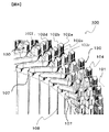
図4は、図3に図示された回転電機の固定子巻線の接合部付近を示す拡大斜視図である。 固定子巻線103は、各相それぞれ、全体がU字形状に形成された複数のセグメントコイル導体102a〜102fを接続して構成される。セグメントコイル導体は、図4において端部を符号130で示す一対の直線状の脚部を有し、図3に示すように、一対の直線状の脚部をU字状に接続する導体引出し部106には、各相ごとの引出し端子106U,106V,106Wが渡り線で接続されている。各コイル導体102a〜102fは、例えば、銅等の導電性金属で形成されている。U字形状の各コイル導体102a〜102fの一対の脚部は、固定子コア101の一端面101a側からスロット105内に挿入されて固定子コア101の他端面101bから突出される。セグメントコイル導体のそれぞれの一対の脚部は異なるスロットに挿入され、異なるスロットから突出した同相の一組の端部130が図4に示すように溶着され、図5で示す接合部104を形成する。
4 is an enlarged perspective view showing the vicinity of the joint portion of the stator winding of the rotating electrical machine shown in FIG. The
スロット105は、その断面形状が固定子コア101の径方向に長い矩形形状に形成されている。各スロット105内には、6個のコイル導体102a〜102fが径方向に並んで挿入されている。各コイル導体102a〜102fのスロット105に挿入される部分には、スロット絶縁紙107(図4参照)が巻き付けられている。スロット絶縁紙107は、固定子コア101と各コイル導体102a〜102fとを絶縁する。また、スロット絶縁紙107は、同じスロット105内に挿入された隣接するコイル導体102a〜102fとを絶縁する。スロット絶縁紙107に替えて、ワニス等の絶縁層を各コイル導体102a〜102fの外周に設けるようにしてもよい。
The
各コイル導体102a〜102fは、固定子コア101の他端面101bから突出する端部130を除いて、エナメルやワニス等の絶縁被膜131により被覆されている。コイル導体102aと102bはたとえばU相の巻線を構成し、コイル導体102cと102dはたとえばV相の巻線を構成し、コイル導体102eと102fはたとえばW相の巻線を構成する。コイル導体102a〜102fの各脚部は、それぞれ、同相の他のコイル導体102a〜102fの各脚部と溶着されて接合され、円環形状の固定子巻線103を形成する。
Each of the
図5は、図4に図示されたコイル導体の接合部を、コイル導体端面側からみた拡大平面図である。図6は、図4に図示されたコイル導体の溶接前の端部付近を、固定子コアの径方向に垂直な方向から見た拡大側面図である。なお、国定子コアの径方向に垂直な方向とは、溶着後を示す図5において、端部130をVI-VI線で切断して見る方向である。コイル導体102a〜102fは、平角線と言われる断面形状が略矩形の部材である。
FIG. 5 is an enlarged plan view of the coil conductor joint shown in FIG. 4 as viewed from the coil conductor end face side. FIG. 6 is an enlarged side view of the vicinity of the end of the coil conductor shown in FIG. 4 before welding as seen from a direction perpendicular to the radial direction of the stator core. In addition, the direction perpendicular to the radial direction of the quorum core is a direction seen by cutting the
コイル導体の接合部104の構造を、コイル導体102aと102bの接合部104aを一例として説明する。
たとえばU相のコイル導体102aの脚部は、図4に示すように、固定子コア101のスロットの最奥部に配置されて固定子コアの一端面101aから突出して周方向に折り曲げられている。図示はされていないが、U相のコイル導体102bの脚部は、固定子コア101のスロットの最奥部よりも内周側に配置されて固定子コアの一端面101aから突出して周方向に折り曲げられている。コイル導体102bは、スロットの最奥部のコイル導体102aの内側に隣接して配置されている。The structure of the
For example, as shown in FIG. 4, the leg portion of the
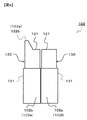
図6に図示されるように、コイル導体102a、102bの端部130では、それぞれ、絶縁被膜131が剥離されている。コイル導体102aの端部130には、固定子コア内周側の平坦な端面121aと、この端面121aから固定子コア外周側に上り勾配で傾斜する堰止め部122aとが形成されている。コイル導体102bの端部130には、固定子コア外周側の平坦な端面121bと、この端面121bから固定子コア内周側に上り勾配で傾斜する堰止め部122bとが形成されている。すなわち、接合される一対のコイル導体102a、102bのうち、固定子コア外側のコイル導体102aには、その固定子外周側長辺に堰止め部122aが形成され、固定子コア内側のコイル導体102bには、その固定子内周側長辺に堰止め部122bが形成されている。コイル導体102c、102dの端部130、コイル導体102e、102fの端部130にもそれぞれ、端面121a〜121fと、堰止め部122c〜122fが形成されている。このように、コイル導体120a〜120fの端部130には、その端面121a〜121fから軸方向に突出する堰止め部122a〜122fが形成されている。そして、コイル導体102aの固定子コア内側に面する側面121sとコイル導体102bの端面121bの固定子コア外側に面する側面121sとは互いに面で接するように配置される。これにより、堰止め部122aと堰止め部122bが対向し、その間の谷間に溶融金属の溜まり空間部WSが形成されている。溜まり空間部WSの底部は平坦な端面121a,121bである。
As shown in FIG. 6, the insulating
コイル導体102a、102bは、TIG(Tungsten Inert Gas)溶接またはTIGろう付けにより接合される。
The
コイル導体102a、102bは、図5に図示されるように、コイル導体102a、102bの端面121a,121bで溶接され溜まり空間部WS(図6参照)に溶融金属が固まった接合材110により接合されている。溶融金属が固化した接合材110は、周方向には、コイル導体102a、102bの端面121の側面から張り出して形成されている。しかし、固定子コアの径方向では、コイル導体102a、102bの堰止め部122a、122bにより溶融金属が堰き止められる。このため、溶接時にコイル導体102aの堰止め部122aの外周側およびコイル導体102bの堰止め部122bの内周側には溶融金属が流出することは無い。すなわち、接合材110は固定子コア半径方向には外周側にも内周側にもはみ出ることがない。
As shown in FIG. 5, the
コイル導体102cと102dの接合部104b、コイル導体102eと102fの接合部104cの構造は、接合部104aと同様である。すなわち、接合部104bでは、コイル導体102c、102dのそれぞれに設けられた堰止め部122c、122dにより、溶接時に、固定子コア101の径方向に溶融金属が流出するのを防止できる。接合部104cでは、コイル導体102e、102fのそれぞれに設けられた堰止め部122e、122fにより、溶接時に、固定子コア101の径方向に溶融金属が流出するのを防止できる。すなわち、コイル導体102cと102dの接合部104b、コイル導体102eと102fの接合部104cにおいても、接合材110は固定子コア半径方向には外周側にも内周側にもはみ出ることがない。
The structures of the joint 104b between the
接合部104aは固定子コア101の最外周側に位置し、接合部104cは固定子コア101の最内周側に位置し、接合部104bは、接合部104aと接合部104cとの中間に位置する。すなわち、接合部104a〜104cは、固定子コア101の径方向に隣り合うように配置されている。しかし、各接合部104a〜104cでは、コイル導体102a〜103fに設けられた堰止め部122a〜122fにより、溶接時に、接合材110が固定子コア101の径方向に隣接する接合部104側に流出するのを堰き止められる。このため、接合材110により、固定子巻線103が短絡するのを防止することができる。
The
上記実施形態1によれば、下記の効果を奏する。なお、以下の効果の説明において、コイル導体102a〜102f、堰止め部122a〜122bを代表して、それぞれ、コイル導体102、堰止め部122という。(1)コイル導体102の各端部130に、接合材110により接合される平坦な端面121と、該端面121から軸方向に突出する堰止め部122とを設けた。このため、接合用の溶融金属は、各堰止め部122で流動が堰き止められ、接合材110が雫状の玉形状を形成するように大きな塊になることはない。これにより、隣接する固定子巻線103同士が短絡するのを防止することができる。
According to the said Embodiment 1, there exist the following effects. In the following description of the effects, the
(2)接合部104において、接合材110を溶融して一対のコイル導体102同士を接合するようにした。このため、TIG溶接やTIGろう付け等、レーザ溶接によらない夭折により接合することが可能となり、設備の大型化および高コスト化を避けることができる。
(2) In the
(3)各堰止め部122は、固定子コア101の径方向に垂直な方向に、端部130の周方向の長さの全長に亘って延在されている。また、一対のコイル導体102の端部130は、固定子コア101の周方向の重なる位置に、径方向に隣接して配置され、堰止め部122は、一対のコイル導体102の端部が対面する側と反対側に形成されている。このため、溶接時に、接合材110は、径方向に隣接する接合部104側に流出するのを堰き止められる。これにより、固定子巻線103が短絡するのを防止することができる。
(3) Each dam member 122 extends in the direction perpendicular to the radial direction of the
(4)堰止め部122を、コイル導体102の端部130の端面121の一辺側からのみ立ち上がるよう設けた。このため、接合材110は、堰止め部122が形成されていない端面121の側方には、張り出すように流動することができ、接合面積を大きくすることができる。
(4) The damming portion 122 is provided so as to rise only from one side of the
−実施形態2−
図7は、本発明の実施形態2を示し、回転電機の固定子の接合部付近を示す拡大斜視図である。図8は、図7に図示されたコイル導体の端部付近をコイル導体端面側から見た拡大平面図であり、図9は、図7に図示された最外周または最内周のコイル導体の溶接前の端部付近を固定子コアの径方向に垂直な方向から見た拡大側面図である。実施形態2では、最外周のコイル導体102aおよび最内周のコイル導体102fには、堰止め部122a、122fが形成されていない。図9に図示されるように、最外周のコイル導体102aの端部130の端面121は、全体が平坦に形成されている。コイル導体102aの内周側に隣接するコイル導体102bの端部130には、内周側の側部に堰止め部122bが形成されている。同様に、最内周のコイル導体102fの端部130の端面121は、全体が平坦に形成されており、コイル導体102fの外周側に隣接するコイル導体102eの端部130には、外周側の側部に堰止め部122eが形成されている。
FIG. 7 is an enlarged perspective view showing the vicinity of the joint portion of the stator of the rotating electrical machine according to the second embodiment of the present invention. 8 is an enlarged plan view of the vicinity of the end portion of the coil conductor shown in FIG. 7 as viewed from the end surface side of the coil conductor, and FIG. 9 is a view of the coil conductor on the outermost or innermost periphery shown in FIG. It is the expanded side view which looked at the edge part vicinity before welding from the direction perpendicular | vertical to the radial direction of a stator core. In the second embodiment, the damming
コイル導体102c、102dの接合部104bの構造は実施形態1と同様である。つまり、図8に図示されるように、コイル導体102cの端部130の外周側の側部およびコイル導体102dの端部130の内周側の側部には、それぞれ、堰止め部122c、122dが形成されている。
従って、接合部104bにおいては、接合材110は、堰止め部122c、122dに堰き止められ、堰止め部122cの外周側および堰止め部122dの内周側に張り出すことはない。これにより、接合部104bが外周側の接合部104aおよび内周側の接合部104cに短絡することは無い。The structure of the joint 104b of the
Therefore, in the
接合部104aにおいては、接合材110は、コイル導体102aの外周側に張り出す。しかし、接合部104aの外周側には、固定子巻線103を構成するコイル導体102は配置されていない。また、接合部104cにおいては、接合材110は、コイル導体102fの内周側に張り出す。しかし、接合部104aの内周側には、固定子巻線103を構成するコイル導体102は配置されていない。従って、接合部104a、104cによって固定子巻線103に短絡が生じることは無い。実施形態2の他の構成は、実施形態1と同様である。実施形態2においても、実施形態1の効果(1)〜(4)と同様な効果を奏する。
In the joining
−実施形態3−
図10は、本発明の実施形態3を示し、コイル導体の端部付近を、固定子コアの径方向に垂直な方向から見た、溶接前の構造を示す拡大側面図である。実施形態3では、接合される一対のコイル導体102a、102bそれぞれの対面する側の側部に、堰止め部122a、122bよりも高さが小さい突起123a、123bを形成した構造を有する。最外周のコイル導体102aの端部130の上部には、外周側の側部に堰止め部122aが形成され、内周側の側部に突起123aが形成されている。堰止め部122aと突起123aとの境界には、平坦な端面121が形成されている。コイル導体102aの内周側のコイル導体102bの端部130の上部には、内周側の側部に堰止め部122bが形成され、内周側の側部に突起123bが形成されている。堰止め部122bと突起123bとの境界には、平坦な端面121が形成されている。
FIG. 10 is an enlarged side view showing a structure before welding in the third embodiment of the present invention, in which the vicinity of the end of the coil conductor is viewed from a direction perpendicular to the radial direction of the stator core. The third embodiment has a structure in which
突起123a、123bは、堰止め部122a、122bより高さが小さく、また、底面の面積も小さい。つまり、突起123a、123bは、堰止め部122a、122bより体積が小さい。突起123aと突起123bは、固定子コア101の周方向の重なる位置に、径方向に隣接して配置されている。堰止め部122a、122bは、それぞれ、突起123aと突起123bとが対面する側と反対側に配置されている。突起123a、123bは、溶接時に、積極的に溶融させるコイル導体102a、102bの部位として形成するものである。突起123a、123bを溶融させることにより、堰止め部122a、122bへの熱影響が緩和される。これにより、堰止め部122a、122bによる溶融金属の堰き止め能力を向上することができる。
The
実施形態3の他の構成は、実施形態1と同様である。実施形態3は、実施形態1の効果(1)〜(3)を奏する。また、実施形態3では、堰止め部122による堰き止め能力を向上することができる。なお、実施形態2と同様、最外周のコイル導体102aおよび最内周のコイル導体102fには、堰止め部122a、122fを形成しないようにしてもよい。
Other configurations of the third embodiment are the same as those of the first embodiment. The third embodiment has the effects (1) to (3) of the first embodiment. In the third embodiment, the damming ability by the damming part 122 can be improved. As in the second embodiment, the damming
図11は、図10に図示されたコイル導体の端部付近の構造の変形例である。図11に図示された実施形態3の変形例では、コイル導体102a、102bの端部130の上部に、平坦な端面121は形成されていない。コイル導体102a、102bの端部130の上部には、それぞれ、堰止め部122a、122bと突起123a、123bとが形成されている。しかし、堰止め部122a、122bと突起123a、123bとの境界部に、平坦な端面121は形成されていない。このような構造においても、実施形態3と同様な効果を奏する。
FIG. 11 shows a modification of the structure near the end of the coil conductor shown in FIG. In the modification of the third embodiment illustrated in FIG. 11, the
なお、上記各実施形態では、1つのスロット105内に、6個のコイル導体102が挿入される構造として例示した。しかし、本発明は、これに限定されるものではなく、1つのスロット105内に挿入されるコイル導体102の数が4個以上の固定子100に適用することができる。
In each of the above embodiments, the structure is shown in which six coil conductors 102 are inserted into one
上記実施形態では、コイル導体102は、平角線といわれる断面形状が略矩形の部材として例示した。しかし、コイル導体102は、丸線型としてもよい。 In the above embodiment, the coil conductor 102 is exemplified as a member having a substantially rectangular cross-sectional shape called a flat wire. However, the coil conductor 102 may be a round wire type.
上記では、種々の実施の形態および変形例を説明したが、本発明はこれらの内容に限定されるものではない。上記各実施形態を、組み合わせることも可能であり、本発明の技術思想の範囲内で考えられるその他の態様も本発明の範囲内に含まれる。 要するに、本発明は、以下の構成を備える種々の回転電機に適用される。本発明による回転電機は、回転子と、固定子コアと固定子巻線とを有する固定子とを備える。そして、固定子巻線は、複数のコイル導体と、固定子コアの端面から突出した複数のコイル導体の端部が接合された接合部とを有し、コイル導体の端部には、接合部の金属の流動を阻止する堰止め部(溶融金属流動阻止堰)が形成されている。 Although various embodiments and modifications have been described above, the present invention is not limited to these contents. The embodiments described above can be combined, and other modes conceivable within the scope of the technical idea of the present invention are also included in the scope of the present invention. In short, the present invention is applied to various rotating electric machines having the following configurations. A rotating electrical machine according to the present invention includes a rotor, and a stator having a stator core and a stator winding. The stator winding includes a plurality of coil conductors and a joint portion where ends of the plurality of coil conductors protruding from the end face of the stator core are joined. A damming portion (molten metal flow blocking dam) for blocking the metal flow is formed.
100 固定子
101 固定子コア
101a 一面
101b 他端面
102a〜102f コイル導体
103 固定子巻線
104、104a〜104c 接合部
105 スロット
110 接合材
122、122a〜122f 堰止め部
121、121a〜121f 端面
123a、123b 突起
130 端部
131 絶縁被覆
200 回転子
201 シャフトDESCRIPTION OF
Claims (4)
スロットを有する固定子コアと固定子巻線とを有する固定子とを備え、
前記固定子巻線は、複数のコイル導体と、前記固定子コアの端面から突出した前記複数のコイル導体の端部が接合された接合部とを有し、
前記コイル導体の端部には、平坦な端面と、前記端面から前記固定子コアの軸方向に突出し、前記接合部の金属の流動を阻止する堰止め部が形成され、
一対の前記コイル導体の端部は、前記固定子コアの周方向の重なる位置に、径方向に隣接して配置され、
前記堰止め部は一対の前記コイル導体の端部が対面する側と反対側にそれぞれ形成され、
前記端面は一対の前記コイル導体の端部が対面する側であって対向する前記堰止め部同士の間に形成され、前記接合部とされた回転電機。 A rotor,
A stator core having a slot and a stator having a stator winding;
The stator winding has a plurality of coil conductors, and a joint portion where the end portions of the plurality of coil conductors protruding from the end face of the stator core are joined,
The end portion of the coil conductor is formed with a flat end surface and a blocking portion that protrudes in the axial direction of the stator core from the end surface and prevents metal flow of the joint portion ,
The ends of the pair of coil conductors are disposed adjacent to each other in the radial direction at the overlapping position in the circumferential direction of the stator core,
The damming portion is formed on the side opposite to the side where the ends of the pair of coil conductors face each other,
The rotating electrical machine wherein the end surfaces are formed on the side where the end portions of the pair of coil conductors face each other and between the opposing weir portions and serve as the joint portions .
前記堰止め部は、前記コイル導体の径方向に垂直な方向に延在している回転電機。 In the rotating electrical machine according to claim 1 ,
The said damming part is a rotary electric machine extended in the direction perpendicular | vertical to the radial direction of the said coil conductor.
前記スロット内に挿入される前記コイル導体の外周側面に絶縁被膜が設けられており、前記コイル導体の前記端部では、前記絶縁被膜が剥離されている回転電機。 In the rotating electrical machine according to claim 1 or 2 ,
A rotating electrical machine in which an insulating coating is provided on an outer peripheral side surface of the coil conductor inserted into the slot, and the insulating coating is peeled off at the end of the coil conductor.
一対の前記コイル導体の前記端部においてTIG溶接またはTIGろう付けにより接合する回転電機の製造方法。 A method of manufacturing the rotating electrical machine according to any one of claims 1 to 3 ,
The manufacturing method of the rotary electric machine joined by TIG welding or TIG brazing in the said edge part of a pair of said coil conductor.
Applications Claiming Priority (3)
| Application Number | Priority Date | Filing Date | Title |
|---|---|---|---|
| JP2015187578 | 2015-09-25 | ||
| JP2015187578 | 2015-09-25 | ||
| PCT/JP2016/072572 WO2017051609A1 (en) | 2015-09-25 | 2016-08-02 | Rotating electric machine and method for manufacturing same |
Publications (2)
| Publication Number | Publication Date |
|---|---|
| JPWO2017051609A1 JPWO2017051609A1 (en) | 2018-03-01 |
| JP6473824B2 true JP6473824B2 (en) | 2019-02-20 |
Family
ID=58386014
Family Applications (1)
| Application Number | Title | Priority Date | Filing Date |
|---|---|---|---|
| JP2017541462A Active JP6473824B2 (en) | 2015-09-25 | 2016-08-02 | Rotating electric machine and manufacturing method thereof |
Country Status (5)
| Country | Link |
|---|---|
| US (1) | US10523073B2 (en) |
| EP (1) | EP3355445B1 (en) |
| JP (1) | JP6473824B2 (en) |
| CN (1) | CN108141083B (en) |
| WO (1) | WO2017051609A1 (en) |
Families Citing this family (8)
| Publication number | Priority date | Publication date | Assignee | Title |
|---|---|---|---|---|
| EP3355445B1 (en) * | 2015-09-25 | 2021-02-17 | Hitachi Automotive Systems, Ltd. | Rotating electric machine and method for manufacturing same |
| JP6642123B2 (en) * | 2016-03-04 | 2020-02-05 | 株式会社デンソー | Rotating electric machine |
| DE102017200688A1 (en) * | 2016-07-08 | 2018-01-11 | Robert Bosch Gmbh | Stator of an electric machine |
| JP6752323B1 (en) * | 2019-04-10 | 2020-09-09 | 三菱電機株式会社 | Stator winding of rotary electric machine and its manufacturing method |
| JP6873191B2 (en) * | 2019-06-19 | 2021-05-19 | 三菱電機株式会社 | Stator and rotary electric machine equipped with this stator |
| DE102019119666A1 (en) * | 2019-07-19 | 2021-01-21 | Gehring E-Tech Gmbh | Method for welding conductor pieces in a component of an electromechanical transducer and component of an electromechanical transducer with welded conductor pieces |
| WO2021048994A1 (en) * | 2019-09-12 | 2021-03-18 | 株式会社 東芝 | Stator and method for manufacturing stator |
| WO2023072562A1 (en) * | 2021-10-26 | 2023-05-04 | Atop S.P.A. | Coupling method for ends of electrical cables of an inductive winding and the like |
Family Cites Families (19)
| Publication number | Priority date | Publication date | Assignee | Title |
|---|---|---|---|---|
| JPS5746641A (en) | 1980-09-03 | 1982-03-17 | Matsushita Electric Works Ltd | Iron-coreless armature |
| US6181043B1 (en) * | 1997-12-10 | 2001-01-30 | Denso Corporation | Alternator for vehicle |
| JP3475818B2 (en) * | 1998-02-19 | 2003-12-10 | 株式会社デンソー | Armature of rotating electric machine and method of manufacturing armature |
| JP2002119003A (en) * | 2000-10-10 | 2002-04-19 | Mitsubishi Electric Corp | Stator for dynamo-electric machine, and manufacturing method thefor |
| FR2821498B1 (en) * | 2001-02-28 | 2004-01-16 | Valeo Equip Electr Moteur | METHOD FOR ASSEMBLING CONDUCTIVE SEGMENTS OF A ROTOR OR STATOR OF A ROTARY ELECTRIC MACHINE |
| JP3709823B2 (en) | 2001-10-05 | 2005-10-26 | 株式会社デンソー | Vehicle alternator |
| JP3786059B2 (en) * | 2002-06-25 | 2006-06-14 | 株式会社デンソー | Segment sequential joining stator coil of rotating electric machine and method for manufacturing the same |
| JP4654068B2 (en) * | 2005-05-24 | 2011-03-16 | 日立オートモティブシステムズ株式会社 | Bonded electric wire, method of processing the bonded electric wire, rotating electric machine stator, rotating electric machine stator manufacturing method, and bonded electric wire manufacturing apparatus |
| DE102006019314A1 (en) * | 2006-04-26 | 2007-10-31 | Robert Bosch Gmbh | Stator`s bar winding manufacturing method for e.g. claw pole generator, of motor vehicle, involves forming fusion zone by arrangement of ends of segments at contacting area, and connecting ends in pairs by contactless fusion welding process |
| JP5565381B2 (en) * | 2011-06-17 | 2014-08-06 | 株式会社デンソー | Rotating electric machine stator |
| US20130106231A1 (en) * | 2011-10-27 | 2013-05-02 | Remy Technologies, L.L.C. | Conductor weld-end length control forming |
| KR101602085B1 (en) * | 2011-12-28 | 2016-03-17 | 도요타지도샤가부시키가이샤 | Rotary electric machine and stator manufacturing method |
| US8443509B1 (en) * | 2012-04-18 | 2013-05-21 | GM Global Technology Operations LLC | Preparing bar-wound stator conductors for electrical interconnection |
| JP5958109B2 (en) | 2012-06-21 | 2016-07-27 | アイシン・エィ・ダブリュ株式会社 | Conductor joining method for rotating electrical machine |
| JP5935587B2 (en) * | 2012-08-10 | 2016-06-15 | 株式会社デンソー | Multi-gap rotating electric machine |
| US20150214820A1 (en) * | 2014-01-24 | 2015-07-30 | Remy Technologies, Llc | Hairpin joint |
| CN107005116B (en) * | 2014-12-26 | 2020-01-10 | 日立汽车系统株式会社 | Stator coil for rotating electrical machine, stator for rotating electrical machine having the coil, and rotating electrical machine having the stator |
| EP3355445B1 (en) * | 2015-09-25 | 2021-02-17 | Hitachi Automotive Systems, Ltd. | Rotating electric machine and method for manufacturing same |
| JP6642123B2 (en) * | 2016-03-04 | 2020-02-05 | 株式会社デンソー | Rotating electric machine |
-
2016
- 2016-08-02 EP EP16848397.2A patent/EP3355445B1/en active Active
- 2016-08-02 US US15/755,226 patent/US10523073B2/en active Active
- 2016-08-02 WO PCT/JP2016/072572 patent/WO2017051609A1/en active Application Filing
- 2016-08-02 CN CN201680036179.3A patent/CN108141083B/en active Active
- 2016-08-02 JP JP2017541462A patent/JP6473824B2/en active Active
Also Published As
| Publication number | Publication date |
|---|---|
| US20180248430A1 (en) | 2018-08-30 |
| CN108141083A (en) | 2018-06-08 |
| JPWO2017051609A1 (en) | 2018-03-01 |
| EP3355445B1 (en) | 2021-02-17 |
| US10523073B2 (en) | 2019-12-31 |
| EP3355445A1 (en) | 2018-08-01 |
| CN108141083B (en) | 2020-04-21 |
| EP3355445A4 (en) | 2019-05-22 |
| WO2017051609A1 (en) | 2017-03-30 |
Similar Documents
| Publication | Publication Date | Title |
|---|---|---|
| JP6473824B2 (en) | Rotating electric machine and manufacturing method thereof | |
| JP6448664B2 (en) | Stator winding of rotating electric machine, stator of rotating electric machine including the same, and rotating electric machine including the same | |
| JP5256669B2 (en) | Brushless motor and electric power steering device | |
| JP6410104B2 (en) | Rotating electric machine stator and rotating electric machine equipped with the stator | |
| JP5541585B2 (en) | Rotating electric machine | |
| JP6259115B2 (en) | Rotating electric machine stator | |
| JP5842856B2 (en) | Rotating electric machine stator | |
| JP5314908B2 (en) | Rotating electric machine stator and rotating electric machine | |
| CN111463942B (en) | Rotating electrical machine | |
| US20100244617A1 (en) | Stator having improved structure for restricting relative displacement between stator core and stator coil | |
| JP6159819B2 (en) | Stator and rotating electric machine equipped with the same | |
| US20240039355A1 (en) | Rotating Electrical Machine, Electric Wheel, and Vehicle | |
| US20230026208A1 (en) | Stator and method of manufacturing same | |
| JP2015057012A (en) | Dynamo-electric machine | |
| JP6839069B2 (en) | Rotating machine | |
| JP7289362B2 (en) | Rotating electric machine | |
| JP2009106008A (en) | Stator for rotating electric machine | |
| JP6946992B2 (en) | Rotating machine | |
| JP2012029444A (en) | Armature for rotary electric machine | |
| JP6657258B2 (en) | Stator, rotating electric machine | |
| JP2019075854A (en) | Stator | |
| JP2023011457A (en) | Electric motor |
Legal Events
| Date | Code | Title | Description |
|---|---|---|---|
| A621 | Written request for application examination |
Free format text: JAPANESE INTERMEDIATE CODE: A621 Effective date: 20171106 |
|
| A131 | Notification of reasons for refusal |
Free format text: JAPANESE INTERMEDIATE CODE: A131 Effective date: 20180703 |
|
| A521 | Request for written amendment filed |
Free format text: JAPANESE INTERMEDIATE CODE: A523 Effective date: 20180801 |
|
| TRDD | Decision of grant or rejection written | ||
| A01 | Written decision to grant a patent or to grant a registration (utility model) |
Free format text: JAPANESE INTERMEDIATE CODE: A01 Effective date: 20190108 |
|
| A61 | First payment of annual fees (during grant procedure) |
Free format text: JAPANESE INTERMEDIATE CODE: A61 Effective date: 20190128 |
|
| R150 | Certificate of patent or registration of utility model |
Ref document number: 6473824 Country of ref document: JP Free format text: JAPANESE INTERMEDIATE CODE: R150 |
|
| S533 | Written request for registration of change of name |
Free format text: JAPANESE INTERMEDIATE CODE: R313533 |
|
| R350 | Written notification of registration of transfer |
Free format text: JAPANESE INTERMEDIATE CODE: R350 |
|
| R250 | Receipt of annual fees |
Free format text: JAPANESE INTERMEDIATE CODE: R250 |