EP2292958A2 - Manuell betätigbares Ansteuermodul - Google Patents
Manuell betätigbares Ansteuermodul Download PDFInfo
- Publication number
- EP2292958A2 EP2292958A2 EP10008949A EP10008949A EP2292958A2 EP 2292958 A2 EP2292958 A2 EP 2292958A2 EP 10008949 A EP10008949 A EP 10008949A EP 10008949 A EP10008949 A EP 10008949A EP 2292958 A2 EP2292958 A2 EP 2292958A2
- Authority
- EP
- European Patent Office
- Prior art keywords
- magnetic field
- valve
- arrangement
- sensor arrangement
- field sensor
- Prior art date
- Legal status (The legal status is an assumption and is not a legal conclusion. Google has not performed a legal analysis and makes no representation as to the accuracy of the status listed.)
- Granted
Links
- 230000005540 biological transmission Effects 0.000 claims description 4
- 230000004913 activation Effects 0.000 claims 7
- 238000000034 method Methods 0.000 description 5
- 230000035945 sensitivity Effects 0.000 description 2
- 238000006073 displacement reaction Methods 0.000 description 1
- 239000011888 foil Substances 0.000 description 1
- 230000006870 function Effects 0.000 description 1
- 230000001960 triggered effect Effects 0.000 description 1
Images
Classifications
-
- F—MECHANICAL ENGINEERING; LIGHTING; HEATING; WEAPONS; BLASTING
- F16—ENGINEERING ELEMENTS AND UNITS; GENERAL MEASURES FOR PRODUCING AND MAINTAINING EFFECTIVE FUNCTIONING OF MACHINES OR INSTALLATIONS; THERMAL INSULATION IN GENERAL
- F16K—VALVES; TAPS; COCKS; ACTUATING-FLOATS; DEVICES FOR VENTING OR AERATING
- F16K31/00—Actuating devices; Operating means; Releasing devices
- F16K31/44—Mechanical actuating means
- F16K31/60—Handles
-
- F—MECHANICAL ENGINEERING; LIGHTING; HEATING; WEAPONS; BLASTING
- F16—ENGINEERING ELEMENTS AND UNITS; GENERAL MEASURES FOR PRODUCING AND MAINTAINING EFFECTIVE FUNCTIONING OF MACHINES OR INSTALLATIONS; THERMAL INSULATION IN GENERAL
- F16K—VALVES; TAPS; COCKS; ACTUATING-FLOATS; DEVICES FOR VENTING OR AERATING
- F16K37/00—Special means in or on valves or other cut-off apparatus for indicating or recording operation thereof, or for enabling an alarm to be given
- F16K37/0025—Electrical or magnetic means
- F16K37/0033—Electrical or magnetic means using a permanent magnet, e.g. in combination with a reed relays
-
- F—MECHANICAL ENGINEERING; LIGHTING; HEATING; WEAPONS; BLASTING
- F16—ENGINEERING ELEMENTS AND UNITS; GENERAL MEASURES FOR PRODUCING AND MAINTAINING EFFECTIVE FUNCTIONING OF MACHINES OR INSTALLATIONS; THERMAL INSULATION IN GENERAL
- F16K—VALVES; TAPS; COCKS; ACTUATING-FLOATS; DEVICES FOR VENTING OR AERATING
- F16K37/00—Special means in or on valves or other cut-off apparatus for indicating or recording operation thereof, or for enabling an alarm to be given
- F16K37/0025—Electrical or magnetic means
- F16K37/0041—Electrical or magnetic means for measuring valve parameters
Definitions
- the invention relates to a Ventilan horrungssystem with a Ventilan horrungsvorraum and a manual operating device for triggering operations in the Ventilan horrungsvorraum.
- valve actuators require either manual mechanical actuations inside the valve control device or complex wired or wireless data transmission techniques (radio and infrared are known in this field), or they are based on traditional operating options such as eg. As the operation of keys that are covered by a front foil.
- the object of the invention is to enable a reliable and comfortable operation of a valve control device.
- valve control system having the features of claim 1.
- Advantageous and expedient refinements of the valve control system according to the invention are specified in the subclaims.
- the valve driving system of the present invention comprises a valve driving device and a manual operating device for triggering operations in the valve driving device.
- the manual actuator has a magnet assembly
- the valve driver has a magnetic field sensor assembly tuned to the magnet assembly of the manual actuator.
- a magnetic field sensor arrangement adapted to the magnet arrangement of the manual actuating device is to be understood here as meaning a sensor arrangement which can register a magnetic field generated by the magnet arrangement when the magnet arrangement is located in the vicinity of the magnetic field sensor arrangement.
- the valve control system according to the invention enables a safe triggering of operations in the valve control device. Opening the housing of the valve control device is just as unnecessary as a wiring, connectors or interfaces for wireless data transmission.
- the technique of the invention is virtually wear-free, since the triggering of operations takes place without contact. The handling is very comfortable, as no keys have to be pressed; it only needs to bring the manual control device in the vicinity of the valve control device and possibly moved.
- the magnetic field arrangement and the associated magnetic field sensor arrangement can be used as far as possible to standard components, so that the inventive solution is inexpensive compared to other techniques.
- the magnetic field sensor arrangement of the valve control device is preferably designed such that it is sensitive to the field strength and / or the field direction of the magnetic field generated by the magnet arrangement.
- Embodiments in which the magnetic field sensor arrangement has at least two sensors and / or the magnet arrangement has at least two permanent magnets are particularly advantageous.
- the use of two or more sensors or magnets makes it possible to differentiate several positions or movements of the manual operating device and to assign different commands.
- this coding possibility of operating actions prevents the majority of sensors or magnets and potential operating errors. Due to the locally very limited profile of the directional field strengths, the probability of the occurrence of interference fields of the same type is significantly reduced compared with the use of only one sensor or magnet.
- the magnetic field sensor arrangement For distinguishing the different positions or movements of the manual actuating device, it is expedient for the magnetic field sensor arrangement to generate characteristic signals as a function of the orientation and / or movement of the magnet arrangement relative to the magnetic field sensor arrangement.
- the signals can then be assigned to different commands, the z. B. are stored in a memory of an electronic control.
- the conditions are met in a simple manner that the generation of different characteristic magnetic fields or magnetic field changes are detected in the valve control device and leads to the triggering of the respective desired operating action.
- the magnet arrangement has at least one electromagnet.
- the one or more electromagnets may be provided alternatively or in addition to one or more permanent magnets.
- the use of electromagnets opens up a wide range of operating and control options.
- a control for the electromagnet with which the current to the electromagnet (on / off, possibly also variation of the current) and / or the current flow direction (adjustment of the polarity of the electromagnet) are variable, can be used to generate many different magnetic fields.
- Such a control predetermined sequences of magnetic fields / changes can be generated with only one electromagnet.
- the magnetic field sensor arrangement recognizes the profiles associated with particular commands.
- such a temporally variable drive is part of a device for transmitting data to the valve drive device.
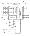
- a valve control device 10 for controlling a pneumatic drive 12 with a pneumatic cylinder 14 for a process valve is exemplified.
- Typical components of such a valve control device 10 are a central electronics 16, an electro-pneumatic control system 18 and a displacement sensor 20 for determining the position of a piston 22 which is movable in the pneumatic cylinder 14.
- valve drive devices are not limited to this type of valve drive devices, but extends to all types of valve drive devices which require operator actions on certain occasions.
- valve drive device 10 comprises a magnetic field sensor arrangement 24 with two or more sensors which can register a change in the field strength and / or the field direction of a magnetic field in the vicinity and output corresponding signals.
- sensors z. B. Hall sensors.
- the magnetic field sensor assembly 24 is protected from external (mechanical) influences by a plastic housing in which the other components of the valve drive device 10 are housed.
- the plastic does not significantly affect the sensitivity of the magnetic field sensor assembly 24.
- the magnetic field sensor arrangement 24 of the valve drive device 10 is matched to a magnet arrangement 26 of a manual operating device 28, which forms a valve drive system together with the valve drive device 10.
- the magnet assembly 26 is received in a plastic housing of the manual actuator 28 and has two or more strong permanent magnets.
- the magnet arrangement 26 and the magnetic field sensor arrangement 24 are matched to one another, in particular with regard to the magnetic field strength and the sensor sensitivity as well as to the geometrical arrangement of the permanent magnets and the sensors. The influence of interference fields is thus almost impossible.
- valve control system By means of the manual operating device 28, operating actions in the valve actuating device 10 can be triggered.
- the manual actuator 28 is brought with the magnet assembly 26 close to the magnetic field sensor assembly 24, as shown in the figure, so that the sensors of the magnetic field sensor assembly 24, the presence and / or the change of the Permanent magnets of the magnet assembly 26 generated magnetic fields (field strength and field direction) can register.
- the magnetic field sensor arrangement 24 Depending on the orientation or movement (in particular movement direction) of the permanent magnets of the magnet arrangement 26 relative to the sensors of the magnetic field sensor arrangement 24, the magnetic field sensor arrangement 24 generates a signal characteristic of the respective orientation and / or movement. In this way, with the manual control device 28 in the valve control device 10 can generate various non-contact signals that are assigned to different, defined in the electronics 16 commands (coding). The commands are triggers of corresponding operations in the valve driver 10.
- the magnet assembly 26 may also include one or more specially shaped permanent magnets.
- specially shaped are meant forms that deviate from the typical linear basic shape of a permanent magnet (bar magnet).
- the number of distinguishable signals or commands generally varies with the number of existing magnets and sensors and their arrangement.
- a control of the electromagnets with which the current flow and / or current flow direction (and thus the polarity of the electromagnet or the electromagnets) can be changed, increases the number of possible command codes. By a suitable time variation of the control and larger amounts of data can be transmitted in a cable-free and non-contact sequentially in the valve control device 10.
Landscapes
- Engineering & Computer Science (AREA)
- General Engineering & Computer Science (AREA)
- Mechanical Engineering (AREA)
- Magnetically Actuated Valves (AREA)
- Indication Of The Valve Opening Or Closing Status (AREA)
Abstract
Description
- Die Erfindung betrifft ein Ventilansteuerungssystem mit einer Ventilansteuerungsvorrichtung und einem Handbetätigungsgerät zum Auslösen von Bedienungshandlungen in der Ventilansteuerungsvorrichtung.
- Bekannte Lösungen im Bereich der Ventilansteuerungen erfordern entweder mechanische Betätigungen von Hand im Inneren der Ventilansteuerungsvorrichtung oder aufwendige leitungsgebundene bzw. drahtlose Datenübertragungstechniken (bekannt sind in diesem Bereich insbesondere Funk und Infrarot), oder sie basieren auf traditionellen Bedienmöglichkeiten wie z. B. die Betätigung von Tasten, die durch eine Frontfolie abgedeckt sind.
- Das Öffnen eines Gehäuses bzw. das Abnehmen eines Gehäuseteils, um an das Innere einer Ventilansteuerungsvorrichtung zu gelangen, ist umständlich und zeitaufwendig. Leitungsgebundene Techniken sind bei den typischerweise verlangten hohen Schutzanforderungen teuer. Auch die drahtlose Datenübertragung, z. B. über Modems, ist für die meisten Anwendungen zu kostspielig. Die Bedienung über Tasten wird nicht immer als komfortabel empfunden und erfordert verlässliche und damit teure Bedienfelder.
- Aufgabe der Erfindung ist es, eine zuverlässige und komfortable Bedienung einer Ventilansteuerungsvorrichtung zu ermöglichen.
- Die Aufgabe wird durch ein Ventilansteuerungssystem mit den Merkmalen des Anspruchs 1 gelöst. Vorteilhafte und zweckmäßige Ausgestaltungen des erfindungsgemäßen Ventilansteuerungssystems sind in den Unteransprüchen angegeben.
- Das erfindungsgemäße Ventilansteuerungssystem umfasst eine Ventilansteuerungsvorrichtung und ein Handbetätigungsgerät zum Auslösen von Bedienungshandlungen in der Ventilansteuerungsvorrichtung. Das Handbetätigungsgerät weist eine Magnetanordnung auf, und die Ventilansteuerungsvorrichtung weist eine auf die Magnetanordnung des Handbetätigungsgeräts abgestimmte Magnetfeldsensoranordnung auf.
- Unter einer auf die Magnetanordnung des Handbetätigungsgeräts abgestimmten Magnetfeldsensoranordnung ist hier eine Sensoranordnung zu verstehen, die ein von der Magnetanordnung erzeugtes Magnetfeld registrieren kann, wenn sich die Magnetanordnung in der Nähe der Magnetfeldsensoranordnung befindet.
- Das erfindungsgemäße Ventilansteuerungssystem ermöglicht eine sichere Auslösung von Bedienungshandlungen in der Ventilansteuerungsvorrichtung. Ein Öffnen des Gehäuses der Ventilansteuerungsvorrichtung ist ebenso wenig notwendig wie eine Verkabelung, Steckverbindungen oder Schnittstellen für eine drahtlose Datenübertragung. Außerdem ist die erfindungsgemäße Technik praktisch verschleißfrei, da die Auslösung von Bedienungshandlungen berührungslos erfolgt. Die Handhabung ist sehr komfortabel, da keine Tasten gedrückt werden müssen; es muss nur das Handbetätigungsgerät in die Nähe der Ventilansteuerungsvorrichtung gebracht und ggf. bewegt werden. Bei der Realisierung der Magnetfeldanordnung und der zugehörigen Magnetfeldsensoranordnung kann weitestgehend auf Standardkomponenten zurückgegriffen werden, sodass die erfindungsgemäße Lösung im Vergleich zu anderen Techniken kostengünstig ist.
- Die Magnetfeldsensoranordnung der Ventilansteuerungsvorrichtung ist vorzugsweise so ausgelegt, dass sie empfindlich für die Feldstärke und/oder die Feldrichtung des von der Magnetanordnung erzeugten Magnetfelds ist.
- Ausführungsformen, bei denen die Magnetfeldsensoranordnung wenigstens zwei Sensoren und/oder die Magnetanordnung wenigstens zwei Permanentmagnete aufweist, sind besonders vorteilhaft. Die Verwendung von zwei oder mehr Sensoren bzw. Magneten ermöglicht es, mehrere Stellungen bzw. Bewegungen des Handbetätigungsgeräts zu unterscheiden und unterschiedlichen Befehlen zuzuordnen. Neben dieser Codiermöglichkeit von Bedienungshandlungen verhindert die Mehrzahl an Sensoren bzw. Magneten auch potenzielle Fehlbedienungen. Aufgrund des lokal sehr begrenzten Profils der gerichteten Feldstärken ist die Wahrscheinlichkeit des Auftretens gleichgearteter Störfelder gegenüber der Verwendung nur eines Sensors bzw. Magneten deutlich reduziert.
- Für die Unterscheidung der verschiedenen Stellungen bzw. Bewegungen des Handbetätigungsgeräts ist es zweckmäßig, dass die Magnetfeldsensoranordnung in Abhängigkeit von der Orientierung und/oder Bewegung der Magnetanordnung relativ zur Magnetfeldsensoranordnung charakteristische Signale erzeugt.
- Die Signale können dann unterschiedlichen Befehlen zugeordnet sein, die z. B. in einem Speicher einer elektronischen Steuerung hinterlegt sind. Damit sind auf einfache Weise die Voraussetzungen dafür erfüllt, dass die Erzeugung unterschiedlicher charakteristischer Magnetfelder bzw. Magnetfeldänderungen in der Ventilansteuerungsvorrichtung erkannt werden und zur Auslösung der jeweils gewünschten Bedienungshandlung führt.
- Eine Weiterbildung der Erfindung sieht vor, dass die Magnetanordnung wenigstens einen Elektromagneten aufweist. Der bzw. die Elektromagnete können alternativ oder zusätzlich zu einem oder mehreren Permanentmagneten vorgesehen sein. Die Verwendung von Elektromagneten eröffnet ein weites Spektrum an Bedienungs- und Steuerungsmöglichkeiten.
- So kann eine Ansteuerung für den Elektromagneten, mit der die Bestromung des Elektromagneten (ein/aus, ggf. auch Variation der Stromstärke) und/oder die Stromflussrichtung (Einstellung der Polarität des Elektromagneten) veränderbar sind, zur Erzeugung vieler unterschiedlicher Magnetfelder genutzt werden.
- Besonders vorteilhaft ist hierbei eine zeitlich variable Ansteuerung. Mit einer solchen Ansteuerung können mit nur einem Elektromagneten vorher festgelegte Abfolgen von Magnetfeldern/änderungen erzeugt werden. Die Magnetfeldsensoranordnung erkennt die Profile, die bestimmten Befehlen zugeordnet sind.
- Gemäß einer Weiterführung dieses Aspekts ist eine solche zeitlich variable Ansteuerung Teil einer Einrichtung zur Übertragung von Daten in die Ventilansteuerungsvorrichtung.
- Die Erfindung wird nachfolgend anhand einer bevorzugten Ausführungsform unter Bezugnahme auf die beigefügte Zeichnung im Detail beschrieben. In der Zeichnung zeigt die einzige Figur eine schematische Darstellung eines erfindungsgemäßen Ventilansteuerungssystems.
- In der Figur ist beispielhaft eine Ventilansteuerungsvorrichtung 10 zur Ansteuerung eines pneumatischen Antriebs 12 mit einem Pneumatikzylinder 14 für ein Prozessventil dargestellt. Typische Komponenten einer solchen Ventilansteuerungsvorrichtung 10 sind eine zentrale Elektronik 16, ein elektro-pneumatisches Stellsystem 18 und ein Wegsensor 20 zur Bestimmung der Position eines im Pneumatikzylinder 14 beweglichen Kolbens 22.
- Die Erfindung ist aber nicht auf diesen Typ von Ventilansteuerungsvorrichtungen beschränkt, sondern erstreckt sich auf alle Arten von Ventilansteuerungsvorrichtungen, die zu bestimmten Gelegenheiten Bedienungshandlungen erfordern.
- Des Weiteren umfasst die Ventilansteuerungsvorrichtung 10 eine Magnetfeldsensoranordnung 24 mit zwei oder mehr Sensoren, die eine Veränderung der Feldstärke und/oder der Feldrichtung eines in der Nähe befindlichen Magnetfelds registrieren können und entsprechende Signale ausgeben. Für diesen Zweck geeignete Sensoren sind z. B. Hall-Sensoren.
- Die Magnetfeldsensoranordnung 24 ist vor äußeren (mechanischen) Einflüssen durch ein Kunststoffgehäuse geschützt, in dem auch die anderen Komponenten der Ventilansteuerungsvorrichtung 10 untergebracht sind. Der Kunststoff beeinträchtigt die Empfindlichkeit der Magnetfeldsensoranordnung 24 nicht wesentlich.
- Die Magnetfeldsensoranordnung 24 der Ventilansteuerungsvorrichtung 10 ist abgestimmt auf eine Magnetanordnung 26 eines Handbetätigungsgeräts 28, das zusammen mit der Ventilansteuerungsvorrichtung 10 ein Ventilansteuerungssystem bildet. Die Magnetanordnung 26 ist in einem Kunststoffgehäuse des Handbetätigungsgeräts 28 aufgenommen und weist zwei oder mehr starke Permanentmagnete auf.
- Die Magnetanordnung 26 und die Magnetfeldsensoranordnung 24 sind aufeinander abgestimmt, insbesondere im Hinblick auf die Magnetfeldstärke und die Sensorempfindlichkeit sowie auf die geometrische Anordnung der Permanentmagnete und der Sensoren. Der Einfluss von Störfeldern ist somit nahezu ausgeschlossen.
- Im Folgenden wird die Funktionsweise des Ventilansteuerungssystems erläutert. Mithilfe des Handbetätigungsgeräts 28 können Bedienungshandlungen in der Ventilansteuerungsvorrichtung 10 ausgelöst werden. Dazu wird das Handbetätigungsgerät 28 mit der Magnetanordnung 26 nahe an die Magnetfeldsensoranordnung 24 herangeführt, wie in der Figur gezeigt, sodass die Sensoren der Magnetfeldsensoranordnung 24 die Präsenz und/oder die Veränderung der von den Permanentmagneten der Magnetanordnung 26 erzeugten Magnetfelder (Feldstärke und Feldrichtung) registrieren können.
- Je nach Orientierung bzw. Bewegung (insbesondere Bewegungsrichtung) der Permanentmagnete der Magnetanordnung 26 relativ zu den Sensoren der Magnetfeldsensoranordnung 24 erzeugt die Magnetfeldsensoranordnung 24 ein für die jeweilige Orientierung und/oder Bewegung charakteristisches Signal. Auf diese Weise lassen sich mit dem Handbetätigungsgerät 28 in der Ventilansteuerungsvorrichtung 10 berührungslos verschiedene Signale erzeugen, die unterschiedlichen, in der Elektronik 16 definierten Befehlen zugeordnet sind (Codierung). Die Befehle stellen Auslöser entsprechender Bedienungshandlungen in der Ventilansteuerungsvorrichtung 10 dar.
- Die Magnetanordnung 26 kann auch einen oder mehrere besonders geformte Permanentmagnete aufweisen. Unter "besonders geformt" sind dabei Formen zu verstehen, die von der typischen linearen Grundform eines Permanentmagneten (Stabmagnet) abweichen.
- Die Anzahl der unterscheidbaren Signale bzw. Befehle variiert allgemein mit der Anzahl der vorhandenen Magnete und Sensoren und deren Anordnung.
- Anstelle von Permanentmagneten können auch ein oder mehrere Elektromagnete vorgesehen sein. Eine Ansteuerung der Elektromagnete, mit der die Bestromung und/oder Stromflussrichtung (und damit die Polarität des Elektromagneten bzw. der Elektromagnete) verändert werden können, erhöht die Anzahl der möglichen Befehlscodes. Durch eine geeignete zeitliche Variation der Ansteuerung können auch größere Datenmengen kabel- und berührungslos sequenziell in die Ventilansteuerungsvorrichtung 10 übertragen werden.
Claims (9)
- Ventilansteuerungssystem mit
einer Ventilansteuerungsvorrichtung (10), und
einem Handbetätigungsgerät (28) zum Auslösen von Bedienungshandlungen in der Ventilansteuerungsvorrichtung (10),
dadurch gekennzeichnet, dass
das Handbetätigungsgerät (30) eine Magnetanordnung (26) aufweist, und
die Ventilansteuerungsvorrichtung (10) eine auf die Magnetanordnung (26) des Handbetätigungsgeräts (28) abgestimmte Magnetfeldsensoranordnung (24) aufweist. - Ventilansteuerungssystem nach Anspruch 1, dadurch gekennzeichnet, dass die Magnetfeldsensoranordnung (24) empfindlich für die Feldstärke und/oder die Feldrichtung des von der Magnetanordnung (26) erzeugten Magnetfelds ist.
- Ventilansteuerungssystem nach Anspruch 1 oder 2, dadurch gekennzeichnet, dass die Magnetfeldsensoranordnung (24) wenigstens zwei Sensoren und/oder die Magnetanordnung (26) wenigstens zwei Permanentmagnete aufweist.
- Ventilansteuerungssystem nach einem der vorhergehenden Ansprüche, dadurch gekennzeichnet, dass die Magnetfeldsensoranordnung (24) in Abhängigkeit von der Orientierung und/oder Bewegung der Magnetanordnung (26) relativ zur Magnetfeldsensoranordnung (24) charakteristische Signale erzeugt.
- Ventilansteuerungssystem nach Anspruch 4, dadurch gekennzeichnet, dass die Signale unterschiedlichen Befehlen zugeordnet sind.
- Ventilansteuerungssystem nach einem der vorhergehenden Ansprüche, dadurch gekennzeichnet, dass die Magnetanordnung (26) wenigstens einen Elektromagneten aufweist.
- Ventilansteuerungssystem nach Anspruch 6, gekennzeichnet durch eine Ansteuerung für den Elektromagneten, mit der die Bestromung des Elektromagneten und/oder die Stromflussrichtung veränderbar sind.
- Ventilansteuerungssystem nach Anspruch 7, dadurch gekennzeichnet, dass die Ansteuerung zeitlich variabel ist.
- Ventilansteuerungssystem nach Anspruch 8, dadurch gekennzeichnet, dass die Ansteuerung Teil einer Einrichtung zur Übertragung von Daten in die Ventilansteuerungsvorrichtung (10) ist.
Applications Claiming Priority (1)
| Application Number | Priority Date | Filing Date | Title |
|---|---|---|---|
| DE202009012183U DE202009012183U1 (de) | 2009-09-08 | 2009-09-08 | Manuell betätigbares Ansteuermodul |
Publications (4)
| Publication Number | Publication Date |
|---|---|
| EP2292958A2 true EP2292958A2 (de) | 2011-03-09 |
| EP2292958A3 EP2292958A3 (de) | 2013-01-09 |
| EP2292958B1 EP2292958B1 (de) | 2013-05-08 |
| EP2292958B2 EP2292958B2 (de) | 2021-09-08 |
Family
ID=41361151
Family Applications (1)
| Application Number | Title | Priority Date | Filing Date |
|---|---|---|---|
| EP10008949.9A Active EP2292958B2 (de) | 2009-09-08 | 2010-08-27 | Manuell betätigbares Ansteuermodul |
Country Status (4)
| Country | Link |
|---|---|
| US (1) | US8622366B2 (de) |
| EP (1) | EP2292958B2 (de) |
| DE (1) | DE202009012183U1 (de) |
| DK (1) | DK2292958T3 (de) |
Cited By (1)
| Publication number | Priority date | Publication date | Assignee | Title |
|---|---|---|---|---|
| DE102018200219A1 (de) | 2018-01-09 | 2019-07-11 | Festo Ag & Co. Kg | Vorrichtung zur Erfassung der Stellung eines Ventilglieds, Ventilbaueinheit, Abfüllanlage und Verfahren zur Inbetriebnahme einer Abfüllanlage |
Families Citing this family (7)
| Publication number | Priority date | Publication date | Assignee | Title |
|---|---|---|---|---|
| DE202012002019U1 (de) | 2012-02-27 | 2012-04-03 | Bürkert Werke GmbH | Manuell betätigbares Ansteuermodul |
| CA2872549C (en) | 2012-05-25 | 2021-04-13 | Mueller International, Llc | Position indicator for valves |
| DE102012105346A1 (de) * | 2012-06-20 | 2013-12-24 | Krones Ag | Antriebsvorrichtung für ein Ventil einer Getränkeabfüllanlage |
| DE102013008033A1 (de) * | 2013-05-13 | 2014-11-13 | Sipos Aktorik Gmbh | Stellantrieb |
| CN109300718B (zh) * | 2018-09-13 | 2019-10-11 | 广东求精电气有限公司 | 一种开关柜防误闭锁装置 |
| JP6783484B1 (ja) * | 2020-03-09 | 2020-11-11 | 金子産業株式会社 | 電磁弁 |
| DE102022124142A1 (de) * | 2021-10-04 | 2023-04-06 | Bürkert Werke GmbH & Co. KG | Verfahren zur Erfassung einer Position eines Signalgebers in einem Wegmesssystem und Wegmesssystem |
Family Cites Families (39)
| Publication number | Priority date | Publication date | Assignee | Title |
|---|---|---|---|---|
| US519727A (en) * | 1894-05-15 | Half to joseph w | ||
| US2788070A (en) * | 1954-02-11 | 1957-04-09 | United Shoe Machinery Corp | Presses for cutting blanks from sheet material |
| US3589242A (en) * | 1969-08-18 | 1971-06-29 | Caterpillar Tractor Co | Single lever control for hoeing scraper components |
| US4131785A (en) * | 1976-02-18 | 1978-12-26 | Electro-Therm, Inc. | Electrically heated liquid tank employing heat pipe heat transfer means |
| DE2626215C3 (de) * | 1976-06-11 | 1979-03-01 | Messerschmitt-Boelkow-Blohm Gmbh, 8000 Muenchen | Drainage-Einrichtung zur Ableitung überschüssiger Flüssigkeit aus Gehirnhöhlen |
| JPS5322803A (en) * | 1976-08-14 | 1978-03-02 | Taiheiyo Eng | Controll system for selfftravelling frame |
| US4559037A (en) * | 1977-12-28 | 1985-12-17 | Siemens Aktiengesellschaft | Device for the pre-programmable infusion of liquids |
| US4541429A (en) * | 1982-05-10 | 1985-09-17 | Prosl Frank R | Implantable magnetically-actuated valve |
| US4481389A (en) * | 1982-08-02 | 1984-11-06 | Liquid Level Lectronics, Inc. | Magnetic control device |
| US4540400A (en) * | 1983-02-17 | 1985-09-10 | Cordis Corporation | Non-invasively adjustable valve |
| US4595390A (en) * | 1983-07-21 | 1986-06-17 | Salomon Hakim | Magnetically-adjustable cerebrospinal fluid shunt valve |
| US4772257A (en) * | 1983-12-08 | 1988-09-20 | Salomon Hakim | External programmer for magnetically-adjustable cerebrospinal fluid shunt valve |
| GB2184260B (en) * | 1985-11-20 | 1989-11-01 | British Gas Plc | Valve operating system |
| GB2187274B (en) * | 1985-12-26 | 1990-05-16 | Furukawa Electric Co Ltd | Heating apparatus |
| FR2602169B1 (fr) * | 1986-07-31 | 1988-11-04 | Fdm Pneumat Sarl Expl | Machine pneumatique portative avec electronique de commande incorporee |
| US5259895A (en) * | 1988-07-05 | 1993-11-09 | Sharp Bruce R | Method of building double walled storage tanks |
| US5139390A (en) * | 1991-02-04 | 1992-08-18 | Rajewski Robert K | Pump and method for drawing vapor from a storage tank without forcibly drawing the vapor from the tank |
| FR2678025A1 (fr) * | 1991-06-21 | 1992-12-24 | Bosch Gmbh Robert | Procede et dispositif pour commander un systeme de dosage de carburant commande par une electrovanne, notamment pour moteur diesel a combustion interne. |
| US5349993A (en) * | 1992-10-13 | 1994-09-27 | Polster, Lieder, Woodruff & Lucchesi, Lc. | Beverage dispensing apparatus and retrofitting kit |
| US5864272A (en) * | 1992-12-02 | 1999-01-26 | Valeo Electronique | Switch having at least two stable positions, especially for a motor vehicle |
| FR2721520B1 (fr) * | 1994-06-24 | 1996-08-30 | Sophysa Sa | Valve sous-cutanée et son dispositif de réglage externe. |
| US5551953A (en) * | 1994-10-31 | 1996-09-03 | Alza Corporation | Electrotransport system with remote telemetry link |
| US5637083A (en) * | 1996-01-19 | 1997-06-10 | Pudenz-Schulte Medical Research Corporation | Implantable adjustable fluid flow control valve |
| US5971009A (en) * | 1997-02-10 | 1999-10-26 | Tanksafe Inc. | Dual containment assembly |
| JP2000356275A (ja) * | 1999-06-15 | 2000-12-26 | Seiko Instruments Inc | 可変圧力弁装置 |
| US6318581B1 (en) * | 2000-03-06 | 2001-11-20 | Snyder Industries, Inc. | Discharge outlet for double wall containment tank assembly |
| JP2001351812A (ja) * | 2000-06-06 | 2001-12-21 | Mikuni Corp | 電磁アクチュエータ及びこれを用いた弁駆動装置並びに位置又は速度センサ |
| FR2812926B1 (fr) * | 2000-08-11 | 2003-06-20 | Chuchu Decayeux | Robinet a condamnation anti-fraude |
| US6516754B2 (en) * | 2001-02-20 | 2003-02-11 | Thomas Chadwick | Convective heating system for liquid storage tank |
| US6990999B2 (en) * | 2003-05-05 | 2006-01-31 | Kjp Investments Llc | Digitally controlled modular valve system |
| JP2005035587A (ja) * | 2003-07-18 | 2005-02-10 | Fuji Photo Film Co Ltd | 貯留タンク |
| US7165572B2 (en) * | 2004-03-31 | 2007-01-23 | Enviro Vault Ltd. | Fluid storage tank with spill containment |
| DE202005020753U1 (de) | 2005-03-01 | 2006-07-20 | American Standard Europe B.V.B.A. | Sanitäres Wasserventil mit berührungsloser Umschaltung zwischen zwei Wasserausläufen |
| DE102005011984B4 (de) | 2005-03-14 | 2007-01-11 | American Standard Europe B.V.B.A. | Elektrisch betriebene Standardarmatur mit getrennt angeordneten Funktionseinheiten |
| DE102005032032B4 (de) * | 2005-07-08 | 2007-04-26 | Erbe Elektromedizin Gmbh | Medizinisches Gerät |
| US7460013B1 (en) * | 2006-08-14 | 2008-12-02 | Charles Agnew Osborne | Remotely actuated flood free zone valve |
| US7784490B1 (en) * | 2007-02-27 | 2010-08-31 | Robert Foresman | Valve monitoring and controlling system |
| US7994886B2 (en) * | 2007-05-17 | 2011-08-09 | Korry Electronics Co. | Fault tolerant solid state push button control system with built in diagnostic |
| DE102007030405B8 (de) | 2007-06-29 | 2009-01-22 | Robert Bosch Gmbh | Elektromagnetischer Aktor mit einer Handhilfsbetätigung für ein Ventil |
-
2009
- 2009-09-08 DE DE202009012183U patent/DE202009012183U1/de not_active Expired - Lifetime
-
2010
- 2010-08-27 EP EP10008949.9A patent/EP2292958B2/de active Active
- 2010-08-27 DK DK10008949.9T patent/DK2292958T3/da active
- 2010-09-08 US US12/877,151 patent/US8622366B2/en active Active
Non-Patent Citations (1)
| Title |
|---|
| None |
Cited By (1)
| Publication number | Priority date | Publication date | Assignee | Title |
|---|---|---|---|---|
| DE102018200219A1 (de) | 2018-01-09 | 2019-07-11 | Festo Ag & Co. Kg | Vorrichtung zur Erfassung der Stellung eines Ventilglieds, Ventilbaueinheit, Abfüllanlage und Verfahren zur Inbetriebnahme einer Abfüllanlage |
Also Published As
| Publication number | Publication date |
|---|---|
| US20110057131A1 (en) | 2011-03-10 |
| EP2292958B1 (de) | 2013-05-08 |
| DE202009012183U1 (de) | 2009-11-26 |
| DK2292958T3 (da) | 2013-08-12 |
| EP2292958B2 (de) | 2021-09-08 |
| US8622366B2 (en) | 2014-01-07 |
| EP2292958A3 (de) | 2013-01-09 |
Similar Documents
| Publication | Publication Date | Title |
|---|---|---|
| EP2292958B1 (de) | Manuell betätigbares Ansteuermodul | |
| DE19749330C2 (de) | Vorrichtung zum Erfassen von Schaltstellungen eines mechanisch betätigbaren Schaltmittels | |
| EP0898369B1 (de) | Kontaktloser Näherungsschalter | |
| DE112012007147B4 (de) | Steuersysteme für Ventilaktuatoren, Ventilaktuatoren und verwandte Verfahren | |
| EP3074836B1 (de) | Stellglied, insbesondere für ein kraftfahrzeug | |
| EP1673866B1 (de) | Sicherheitsschalter, insbesondere not-aus-schalter, zum sicheren abschalten eines gefahrbringenden gerätes | |
| DE202012002019U1 (de) | Manuell betätigbares Ansteuermodul | |
| EP1880400A1 (de) | Dreh-/drücksteller | |
| EP2659318B1 (de) | Verfahren und vorrichtung zum bereitstellen einer bewegungsangabe, insbesondere für eine blockiererkennung eines schliesssystems | |
| EP2087410A1 (de) | Drehsteller mit magnetisch erzeugter haptik | |
| EP1816290B1 (de) | Quasi-Feststehender Türgriff mit taktiler Rückmeldung | |
| DE102014017480A1 (de) | Stellglied, insbesondere für ein Kraftfahrzeug | |
| DE102007024874A1 (de) | Betätigungselement einer Fahrzeug-Benutzer-Schnittstelle | |
| DE102017210443A1 (de) | Drehsteuervorrichtung für ein Fahrzeug | |
| DE102014213405B4 (de) | Näherungsschalter mit einem magnetischen Drehschalter | |
| DE102012017266B4 (de) | Bedienvorrichtung für eine Funktionseinrichtung eines Kraftfahrzeugs sowie Kraftfahrzeug | |
| EP1903418A1 (de) | Vorrichtung zur Umwandlung mechanischer Bewegungen in elektrische Signale | |
| EP1850093A1 (de) | Drehwinkelsensor auf magnetosensitiver Basis | |
| EP2895348A1 (de) | Bedienvorrichtung für eine funktionseinrichtung eines kraftfahrzeugs | |
| DE202004009047U1 (de) | Positionsgeber für Tore | |
| DE102014018455A1 (de) | Verfahren zum Steuern einer Funktionseinrichtung zum flächigen Abschirmen eines Bereichs des Kraftfahrzeugs | |
| EP0832004A1 (de) | Vorrichtung und verfahren zur elektronischen überwachung eines in einem fahrzeug angeordneten verstellantriebs | |
| DE10349937B4 (de) | Einrichtung zur berührungslosen Erfassung von Schaltstellungen in Kraftfahrzeugschließsystemen | |
| DE102014017481A1 (de) | Stellglied, insbesondere für ein Kraftfahrzeug | |
| DE20309093U1 (de) | Vorrichtung zur Steuerung des Schließvorganges von im wesentlichen translatorisch angetriebenen Torbehängen oder Torblättern eines Tores |
Legal Events
| Date | Code | Title | Description |
|---|---|---|---|
| PUAI | Public reference made under article 153(3) epc to a published international application that has entered the european phase |
Free format text: ORIGINAL CODE: 0009012 |
|
| AK | Designated contracting states |
Kind code of ref document: A2 Designated state(s): AL AT BE BG CH CY CZ DE DK EE ES FI FR GB GR HR HU IE IS IT LI LT LU LV MC MK MT NL NO PL PT RO SE SI SK SM TR |
|
| AX | Request for extension of the european patent |
Extension state: BA ME RS |
|
| PUAL | Search report despatched |
Free format text: ORIGINAL CODE: 0009013 |
|
| AK | Designated contracting states |
Kind code of ref document: A3 Designated state(s): AL AT BE BG CH CY CZ DE DK EE ES FI FR GB GR HR HU IE IS IT LI LT LU LV MC MK MT NL NO PL PT RO SE SI SK SM TR |
|
| AX | Request for extension of the european patent |
Extension state: BA ME RS |
|
| RIC1 | Information provided on ipc code assigned before grant |
Ipc: F16K 31/60 20060101ALI20121203BHEP Ipc: F16K 37/00 20060101AFI20121203BHEP Ipc: F16K 31/08 20060101ALI20121203BHEP Ipc: F16K 31/05 20060101ALI20121203BHEP |
|
| 17P | Request for examination filed |
Effective date: 20121218 |
|
| GRAP | Despatch of communication of intention to grant a patent |
Free format text: ORIGINAL CODE: EPIDOSNIGR1 |
|
| GRAS | Grant fee paid |
Free format text: ORIGINAL CODE: EPIDOSNIGR3 |
|
| GRAA | (expected) grant |
Free format text: ORIGINAL CODE: 0009210 |
|
| STAA | Information on the status of an ep patent application or granted ep patent |
Free format text: STATUS: THE PATENT HAS BEEN GRANTED |
|
| AK | Designated contracting states |
Kind code of ref document: B1 Designated state(s): AL AT BE BG CH CY CZ DE DK EE ES FI FR GB GR HR HU IE IS IT LI LT LU LV MC MK MT NL NO PL PT RO SE SI SK SM TR |
|
| REG | Reference to a national code |
Ref country code: GB Ref legal event code: FG4D Free format text: NOT ENGLISH |
|
| REG | Reference to a national code |
Ref country code: CH Ref legal event code: EP Ref country code: AT Ref legal event code: REF Ref document number: 611262 Country of ref document: AT Kind code of ref document: T Effective date: 20130515 Ref country code: CH Ref legal event code: NV Representative=s name: BUGNION S.A., CH |
|
| REG | Reference to a national code |
Ref country code: IE Ref legal event code: FG4D Free format text: LANGUAGE OF EP DOCUMENT: GERMAN |
|
| REG | Reference to a national code |
Ref country code: DE Ref legal event code: R096 Ref document number: 502010003248 Country of ref document: DE Effective date: 20130704 |
|
| REG | Reference to a national code |
Ref country code: DK Ref legal event code: T3 |
|
| REG | Reference to a national code |
Ref country code: SE Ref legal event code: TRGR |
|
| REG | Reference to a national code |
Ref country code: LT Ref legal event code: MG4D |
|
| REG | Reference to a national code |
Ref country code: NL Ref legal event code: VDEP Effective date: 20130508 |
|
| PG25 | Lapsed in a contracting state [announced via postgrant information from national office to epo] |
Ref country code: IS Free format text: LAPSE BECAUSE OF FAILURE TO SUBMIT A TRANSLATION OF THE DESCRIPTION OR TO PAY THE FEE WITHIN THE PRESCRIBED TIME-LIMIT Effective date: 20130908 Ref country code: ES Free format text: LAPSE BECAUSE OF FAILURE TO SUBMIT A TRANSLATION OF THE DESCRIPTION OR TO PAY THE FEE WITHIN THE PRESCRIBED TIME-LIMIT Effective date: 20130819 Ref country code: PT Free format text: LAPSE BECAUSE OF FAILURE TO SUBMIT A TRANSLATION OF THE DESCRIPTION OR TO PAY THE FEE WITHIN THE PRESCRIBED TIME-LIMIT Effective date: 20130909 Ref country code: SI Free format text: LAPSE BECAUSE OF FAILURE TO SUBMIT A TRANSLATION OF THE DESCRIPTION OR TO PAY THE FEE WITHIN THE PRESCRIBED TIME-LIMIT Effective date: 20130508 Ref country code: LT Free format text: LAPSE BECAUSE OF FAILURE TO SUBMIT A TRANSLATION OF THE DESCRIPTION OR TO PAY THE FEE WITHIN THE PRESCRIBED TIME-LIMIT Effective date: 20130508 Ref country code: NO Free format text: LAPSE BECAUSE OF FAILURE TO SUBMIT A TRANSLATION OF THE DESCRIPTION OR TO PAY THE FEE WITHIN THE PRESCRIBED TIME-LIMIT Effective date: 20130808 Ref country code: GR Free format text: LAPSE BECAUSE OF FAILURE TO SUBMIT A TRANSLATION OF THE DESCRIPTION OR TO PAY THE FEE WITHIN THE PRESCRIBED TIME-LIMIT Effective date: 20130809 Ref country code: FI Free format text: LAPSE BECAUSE OF FAILURE TO SUBMIT A TRANSLATION OF THE DESCRIPTION OR TO PAY THE FEE WITHIN THE PRESCRIBED TIME-LIMIT Effective date: 20130508 |
|
| PG25 | Lapsed in a contracting state [announced via postgrant information from national office to epo] |
Ref country code: HR Free format text: LAPSE BECAUSE OF FAILURE TO SUBMIT A TRANSLATION OF THE DESCRIPTION OR TO PAY THE FEE WITHIN THE PRESCRIBED TIME-LIMIT Effective date: 20130508 Ref country code: BG Free format text: LAPSE BECAUSE OF FAILURE TO SUBMIT A TRANSLATION OF THE DESCRIPTION OR TO PAY THE FEE WITHIN THE PRESCRIBED TIME-LIMIT Effective date: 20130808 Ref country code: PL Free format text: LAPSE BECAUSE OF FAILURE TO SUBMIT A TRANSLATION OF THE DESCRIPTION OR TO PAY THE FEE WITHIN THE PRESCRIBED TIME-LIMIT Effective date: 20130508 Ref country code: CY Free format text: LAPSE BECAUSE OF FAILURE TO SUBMIT A TRANSLATION OF THE DESCRIPTION OR TO PAY THE FEE WITHIN THE PRESCRIBED TIME-LIMIT Effective date: 20130508 |
|
| PG25 | Lapsed in a contracting state [announced via postgrant information from national office to epo] |
Ref country code: LV Free format text: LAPSE BECAUSE OF FAILURE TO SUBMIT A TRANSLATION OF THE DESCRIPTION OR TO PAY THE FEE WITHIN THE PRESCRIBED TIME-LIMIT Effective date: 20130508 |
|
| PLBI | Opposition filed |
Free format text: ORIGINAL CODE: 0009260 |
|
| PG25 | Lapsed in a contracting state [announced via postgrant information from national office to epo] |
Ref country code: SK Free format text: LAPSE BECAUSE OF FAILURE TO SUBMIT A TRANSLATION OF THE DESCRIPTION OR TO PAY THE FEE WITHIN THE PRESCRIBED TIME-LIMIT Effective date: 20130508 Ref country code: EE Free format text: LAPSE BECAUSE OF FAILURE TO SUBMIT A TRANSLATION OF THE DESCRIPTION OR TO PAY THE FEE WITHIN THE PRESCRIBED TIME-LIMIT Effective date: 20130508 Ref country code: CZ Free format text: LAPSE BECAUSE OF FAILURE TO SUBMIT A TRANSLATION OF THE DESCRIPTION OR TO PAY THE FEE WITHIN THE PRESCRIBED TIME-LIMIT Effective date: 20130508 |
|
| 26 | Opposition filed |
Opponent name: FESTO AG & CO. KG Effective date: 20140114 |
|
| BERE | Be: lapsed |
Owner name: BURKERT WERKE G.M.B.H. Effective date: 20130831 |
|
| PG25 | Lapsed in a contracting state [announced via postgrant information from national office to epo] |
Ref country code: NL Free format text: LAPSE BECAUSE OF FAILURE TO SUBMIT A TRANSLATION OF THE DESCRIPTION OR TO PAY THE FEE WITHIN THE PRESCRIBED TIME-LIMIT Effective date: 20130508 Ref country code: RO Free format text: LAPSE BECAUSE OF FAILURE TO SUBMIT A TRANSLATION OF THE DESCRIPTION OR TO PAY THE FEE WITHIN THE PRESCRIBED TIME-LIMIT Effective date: 20130508 Ref country code: IT Free format text: LAPSE BECAUSE OF FAILURE TO SUBMIT A TRANSLATION OF THE DESCRIPTION OR TO PAY THE FEE WITHIN THE PRESCRIBED TIME-LIMIT Effective date: 20130508 |
|
| PLAX | Notice of opposition and request to file observation + time limit sent |
Free format text: ORIGINAL CODE: EPIDOSNOBS2 |
|
| REG | Reference to a national code |
Ref country code: DE Ref legal event code: R026 Ref document number: 502010003248 Country of ref document: DE Effective date: 20140114 |
|
| PG25 | Lapsed in a contracting state [announced via postgrant information from national office to epo] |
Ref country code: MC Free format text: LAPSE BECAUSE OF FAILURE TO SUBMIT A TRANSLATION OF THE DESCRIPTION OR TO PAY THE FEE WITHIN THE PRESCRIBED TIME-LIMIT Effective date: 20130508 |
|
| REG | Reference to a national code |
Ref country code: IE Ref legal event code: MM4A |
|
| REG | Reference to a national code |
Ref country code: FR Ref legal event code: ST Effective date: 20140430 |
|
| PG25 | Lapsed in a contracting state [announced via postgrant information from national office to epo] |
Ref country code: BE Free format text: LAPSE BECAUSE OF NON-PAYMENT OF DUE FEES Effective date: 20130831 |
|
| PLBB | Reply of patent proprietor to notice(s) of opposition received |
Free format text: ORIGINAL CODE: EPIDOSNOBS3 |
|
| PG25 | Lapsed in a contracting state [announced via postgrant information from national office to epo] |
Ref country code: IE Free format text: LAPSE BECAUSE OF NON-PAYMENT OF DUE FEES Effective date: 20130827 |
|
| PG25 | Lapsed in a contracting state [announced via postgrant information from national office to epo] |
Ref country code: FR Free format text: LAPSE BECAUSE OF NON-PAYMENT OF DUE FEES Effective date: 20130902 |
|
| PLAB | Opposition data, opponent's data or that of the opponent's representative modified |
Free format text: ORIGINAL CODE: 0009299OPPO |
|
| R26 | Opposition filed (corrected) |
Opponent name: FESTO AG & CO. KG Effective date: 20140114 |
|
| PG25 | Lapsed in a contracting state [announced via postgrant information from national office to epo] |
Ref country code: SM Free format text: LAPSE BECAUSE OF FAILURE TO SUBMIT A TRANSLATION OF THE DESCRIPTION OR TO PAY THE FEE WITHIN THE PRESCRIBED TIME-LIMIT Effective date: 20130508 |
|
| PG25 | Lapsed in a contracting state [announced via postgrant information from national office to epo] |
Ref country code: MT Free format text: LAPSE BECAUSE OF FAILURE TO SUBMIT A TRANSLATION OF THE DESCRIPTION OR TO PAY THE FEE WITHIN THE PRESCRIBED TIME-LIMIT Effective date: 20130508 Ref country code: TR Free format text: LAPSE BECAUSE OF FAILURE TO SUBMIT A TRANSLATION OF THE DESCRIPTION OR TO PAY THE FEE WITHIN THE PRESCRIBED TIME-LIMIT Effective date: 20130508 |
|
| PG25 | Lapsed in a contracting state [announced via postgrant information from national office to epo] |
Ref country code: LU Free format text: LAPSE BECAUSE OF NON-PAYMENT OF DUE FEES Effective date: 20130827 Ref country code: MK Free format text: LAPSE BECAUSE OF FAILURE TO SUBMIT A TRANSLATION OF THE DESCRIPTION OR TO PAY THE FEE WITHIN THE PRESCRIBED TIME-LIMIT Effective date: 20130508 Ref country code: HU Free format text: LAPSE BECAUSE OF FAILURE TO SUBMIT A TRANSLATION OF THE DESCRIPTION OR TO PAY THE FEE WITHIN THE PRESCRIBED TIME-LIMIT; INVALID AB INITIO Effective date: 20100827 |
|
| RDAF | Communication despatched that patent is revoked |
Free format text: ORIGINAL CODE: EPIDOSNREV1 |
|
| APBM | Appeal reference recorded |
Free format text: ORIGINAL CODE: EPIDOSNREFNO |
|
| APBP | Date of receipt of notice of appeal recorded |
Free format text: ORIGINAL CODE: EPIDOSNNOA2O |
|
| APAH | Appeal reference modified |
Free format text: ORIGINAL CODE: EPIDOSCREFNO |
|
| APBQ | Date of receipt of statement of grounds of appeal recorded |
Free format text: ORIGINAL CODE: EPIDOSNNOA3O |
|
| PGFP | Annual fee paid to national office [announced via postgrant information from national office to epo] |
Ref country code: DK Payment date: 20160819 Year of fee payment: 7 |
|
| PGFP | Annual fee paid to national office [announced via postgrant information from national office to epo] |
Ref country code: AT Payment date: 20160822 Year of fee payment: 7 |
|
| RAP2 | Party data changed (patent owner data changed or rights of a patent transferred) |
Owner name: BUERKERT WERKE GMBH & CO. KG |
|
| PLBP | Opposition withdrawn |
Free format text: ORIGINAL CODE: 0009264 |
|
| REG | Reference to a national code |
Ref country code: DK Ref legal event code: EBP Effective date: 20170831 |
|
| REG | Reference to a national code |
Ref country code: AT Ref legal event code: MM01 Ref document number: 611262 Country of ref document: AT Kind code of ref document: T Effective date: 20170827 |
|
| PG25 | Lapsed in a contracting state [announced via postgrant information from national office to epo] |
Ref country code: AT Free format text: LAPSE BECAUSE OF NON-PAYMENT OF DUE FEES Effective date: 20170827 |
|
| PG25 | Lapsed in a contracting state [announced via postgrant information from national office to epo] |
Ref country code: DK Free format text: LAPSE BECAUSE OF NON-PAYMENT OF DUE FEES Effective date: 20170831 |
|
| PG25 | Lapsed in a contracting state [announced via postgrant information from national office to epo] |
Ref country code: AL Free format text: LAPSE BECAUSE OF FAILURE TO SUBMIT A TRANSLATION OF THE DESCRIPTION OR TO PAY THE FEE WITHIN THE PRESCRIBED TIME-LIMIT Effective date: 20130508 |
|
| PGFP | Annual fee paid to national office [announced via postgrant information from national office to epo] |
Ref country code: CH Payment date: 20190821 Year of fee payment: 10 |
|
| PLAB | Opposition data, opponent's data or that of the opponent's representative modified |
Free format text: ORIGINAL CODE: 0009299OPPO |
|
| REG | Reference to a national code |
Ref country code: CH Ref legal event code: PL |
|
| APBU | Appeal procedure closed |
Free format text: ORIGINAL CODE: EPIDOSNNOA9O |
|
| PG25 | Lapsed in a contracting state [announced via postgrant information from national office to epo] |
Ref country code: CH Free format text: LAPSE BECAUSE OF NON-PAYMENT OF DUE FEES Effective date: 20200831 Ref country code: LI Free format text: LAPSE BECAUSE OF NON-PAYMENT OF DUE FEES Effective date: 20200831 |
|
| PUAH | Patent maintained in amended form |
Free format text: ORIGINAL CODE: 0009272 |
|
| STAA | Information on the status of an ep patent application or granted ep patent |
Free format text: STATUS: PATENT MAINTAINED AS AMENDED |
|
| 27A | Patent maintained in amended form |
Effective date: 20210908 |
|
| AK | Designated contracting states |
Kind code of ref document: B2 Designated state(s): AL AT BE BG CH CY CZ DE DK EE ES FI FR GB GR HR HU IE IS IT LI LT LU LV MC MK MT NL NO PL PT RO SE SI SK SM TR |
|
| REG | Reference to a national code |
Ref country code: DE Ref legal event code: R102 Ref document number: 502010003248 Country of ref document: DE |
|
| REG | Reference to a national code |
Ref country code: SE Ref legal event code: RPEO |
|
| P01 | Opt-out of the competence of the unified patent court (upc) registered |
Effective date: 20230523 |
|
| PGFP | Annual fee paid to national office [announced via postgrant information from national office to epo] |
Ref country code: GB Payment date: 20230822 Year of fee payment: 14 |
|
| PGFP | Annual fee paid to national office [announced via postgrant information from national office to epo] |
Ref country code: SE Payment date: 20230821 Year of fee payment: 14 Ref country code: DE Payment date: 20230821 Year of fee payment: 14 |