EP2292957A1 - Lever device and hydraulic valve with same - Google Patents
Lever device and hydraulic valve with same Download PDFInfo
- Publication number
- EP2292957A1 EP2292957A1 EP09011379A EP09011379A EP2292957A1 EP 2292957 A1 EP2292957 A1 EP 2292957A1 EP 09011379 A EP09011379 A EP 09011379A EP 09011379 A EP09011379 A EP 09011379A EP 2292957 A1 EP2292957 A1 EP 2292957A1
- Authority
- EP
- European Patent Office
- Prior art keywords
- engagement
- lever device
- locking
- actuating shaft
- locking part
- Prior art date
- Legal status (The legal status is an assumption and is not a legal conclusion. Google has not performed a legal analysis and makes no representation as to the accuracy of the status listed.)
- Granted
Links
- 230000000295 complement effect Effects 0.000 claims description 2
- 230000000903 blocking effect Effects 0.000 description 3
- 235000010678 Paulownia tomentosa Nutrition 0.000 description 2
- 240000002834 Paulownia tomentosa Species 0.000 description 2
- 238000004519 manufacturing process Methods 0.000 description 2
- 230000001419 dependent effect Effects 0.000 description 1
- 230000002349 favourable effect Effects 0.000 description 1
Images

Classifications
-
- G—PHYSICS
- G05—CONTROLLING; REGULATING
- G05G—CONTROL DEVICES OR SYSTEMS INSOFAR AS CHARACTERISED BY MECHANICAL FEATURES ONLY
- G05G1/00—Controlling members, e.g. knobs or handles; Assemblies or arrangements thereof; Indicating position of controlling members
- G05G1/08—Controlling members for hand actuation by rotary movement, e.g. hand wheels
- G05G1/10—Details, e.g. of discs, knobs, wheels or handles
-
- F—MECHANICAL ENGINEERING; LIGHTING; HEATING; WEAPONS; BLASTING
- F16—ENGINEERING ELEMENTS AND UNITS; GENERAL MEASURES FOR PRODUCING AND MAINTAINING EFFECTIVE FUNCTIONING OF MACHINES OR INSTALLATIONS; THERMAL INSULATION IN GENERAL
- F16K—VALVES; TAPS; COCKS; ACTUATING-FLOATS; DEVICES FOR VENTING OR AERATING
- F16K35/00—Means to prevent accidental or unauthorised actuation
- F16K35/02—Means to prevent accidental or unauthorised actuation to be locked or disconnected by means of a pushing or pulling action
- F16K35/022—Means to prevent accidental or unauthorised actuation to be locked or disconnected by means of a pushing or pulling action the locking mechanism being actuated by a separate actuating element
- F16K35/025—Means to prevent accidental or unauthorised actuation to be locked or disconnected by means of a pushing or pulling action the locking mechanism being actuated by a separate actuating element said actuating element being operated manually (e.g. a push-button located in the valve actuator)
-
- G—PHYSICS
- G05—CONTROLLING; REGULATING
- G05G—CONTROL DEVICES OR SYSTEMS INSOFAR AS CHARACTERISED BY MECHANICAL FEATURES ONLY
- G05G5/00—Means for preventing, limiting or returning the movements of parts of a control mechanism, e.g. locking controlling member
- G05G5/06—Means for preventing, limiting or returning the movements of parts of a control mechanism, e.g. locking controlling member for holding members in one or a limited number of definite positions only
Definitions
- the present invention relates to a lever device for actuating in particular a hydraulic valve, comprising an actuating shaft for connection to the hydraulic valve and an actuating lever connected to the actuating shaft, by the handling of the actuating shaft is rotatable, and with a locking device for fixing the actuating shaft in a plurality of locking positions, wherein the locking means comprises an engaging member connected to the actuating shaft and / or the actuating lever and a rotatably mounted locking member and engaging and locking member complementary engagement elements, wherein the engagement member of the locking member from a release position outside the range of movement of the engagement member can be brought into an engagement position, in the form-fitting engaging the engagement elements of engagement part and locking part and the actuating shaft interlocking. Moreover, the invention relates to a hydraulic valve with such a lever device.
- Lever devices of the above type are used in particular in agricultural machines and tractors to provide hydraulic valves for handling one on the tractor provided working device, such as a plow to operate.
- the actuating shaft is rotated via the actuating lever, so that via the hydraulic valve causes a lowering or lifting of the plow.
- locking means are known, with which the actuating shaft is held securely in at least one, usually a plurality of locking position.
- a known locking device comprises a threaded bolt rotatably held as a locking bolt, which can be screwed in the locking position in a corresponding recess of an engagement part which is connected to the actuating shaft.
- the disadvantage is that the locking of the actuating shaft is time-consuming and the production of the locking device is expensive.
- Object of the present invention is therefore to provide a lever device of the type mentioned above, which is easy to operate and has a simple structure.
- engagement element is mounted on the locking member such that it is pivotable by rotational movement of the locking part from the release position into the engaged position.
- the basic idea of the invention is thus to transfer the engagement element or the engagement elements of the locking part by a short rotation of the locking part, for example a quarter turn, from the engagement position into the release position or vice versa.
- a short rotation of the locking part for example a quarter turn
- there is a pivoting of the engagement member or the engagement elements so that it or they blocked in the engaged position, an engagement element of the engagement member by positive engagement.
- the blocking of the engagement member of the engagement member causes the locking of the actuating shaft.
- a particularly simple embodiment is obtained when the locking member is mounted immovably in the axial direction.
- the locking member is transferred by a pure rotational movement of the release position in the engaged position, wherein the engagement member of the locking member is pivoted exclusively.
- the locking part is designed substantially as a shaft.
- the locking member may be positioned so that its longitudinal axis is substantially perpendicular to the axis of the actuating shaft.
- the locking member can block the actuating shaft in a radial region, so that the resulting lever is short and only small forces act thereon.
- the engagement element of the locking part is expediently provided on the engagement part-side end region. As a result, the locking part can be kept short.
- the locking part at its end portion opposite the engagement element has a turning handle in order to be able to turn the locking part manually.
- the rotary handle can also be designed as a lever to allow the introduction of large rotational forces in the locking part.
- the engagement element of the locking part may be formed as two spaced-apart projections, between which the or the engagement element (s) can pass on the engagement part in the release position of the locking part or can.
- the two spaced protrusions include a groove therebetween which is aligned in the direction of movement of the engaging element (s) of the engaging part, whereas the two protrusions in the engaged position sandwich and lock the engaging element on the engaging part in the direction of movement.
- a particularly simple embodiment of the engagement element (s) of the engagement part results when it is or are formed as a projection or projections.
- the engagement member (s) of the engagement part may extend substantially radially of the operation shaft. This allows the Engagement with the engagement element of the locking member can be reliably brought about, and there is a secure blocking of the actuating shaft.
- the engagement part may comprise a plurality of engagement elements, wherein each engagement element of the engagement part can be brought into engagement with the engagement element of the locking part.
- each engagement element of the engagement part can be brought into engagement with the engagement element of the locking part.
- the lever device can thus take place a lock in the various locking positions.
- a particularly simple arrangement results for the engagement elements of the engagement part, if they are arranged on a common circular path around the actuating shaft.
- the engagement members of the engagement member can be moved by rotating the operation shaft in the engagement portion of the locking member and block the operating shaft in a simple manner by engagement of the engagement elements of the locking part and engagement member in the various locking positions.
- the engagement part can be designed as a circular segment disc and positioned so that its circle center is located on the longitudinal axis of the actuating shaft.
- engagement elements can be attached to the engagement part, which rotate upon rotation of the actuating shaft on a circular path about the central axis and in each case at a predetermined position with the engagement element of the locking part intermeshable are.
- the engagement member (s) of the engagement member may be provided on the outer periphery of the circular segment disc to obtain favorable leverage through the full radius of the circular segment disc.
- the circular segment disc can be positioned such that its disc plane is aligned perpendicular to the longitudinal axis of the actuating shaft. This allows for easy manufacture and assembly of the circular segment disc and the establishment of a stable connection with the actuating shaft.
- the engagement member may be attached to the operating lever.
- the operating lever is to be connected to the operating shaft and the structure of the lever device is simple. Since of the locking device and the actuating lever in principle equal forces can act on the actuating shaft, they require an equally stable connection with it. However, rotationally fixed connections are difficult to produce on a shaft, and one of these connections can be dispensed with when the engagement part is attached to the actuating lever.
- the engaging member may be connected to the operating lever through a large axial portion so that acting forces are distributed to this entire portion and the connection between the engaging member and the operating lever is stable.
- the engagement member may also be connected to the actuating shaft to increase the stability of the connection.
- the subject of the present invention is furthermore a hydraulic valve with a lever device according to the invention.
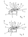
- the lever device 1 shown in the figures comprises an actuating shaft 2 for connection to a hydraulic valve (not shown) and an actuating lever 3 connected in a rotationally fixed manner to the actuating shaft 2.
- the lever device 1 further comprises a locking device 4 with an engagement part 5 which is attached at one of its lateral edges to the actuating lever 3 and additionally at its lower end to the actuating shaft 2, and a locking part 6, which in a housing 7, which is the central Area of the lever device 1 surrounds, is held. In this case, the viewer facing wall of the housing 7 is omitted in all figures, so that the lever device 1 is visible.
- the engagement member 5 is designed as a circular segment disc whose circle center is located on the longitudinal axis of the actuating shaft 2 and the disc plane is aligned perpendicular to the longitudinal axis of the actuating shaft 2.
- the locking part 6 comprises a shaft 9 which is rotatably mounted on a bearing element 10 and a passage 11 of the locking part 6 through the housing 7, but axially non-displaceable.
- the locking part 6 is positioned such that its longitudinal axis extends substantially perpendicular to the axis of the actuating shaft 2.
- an engagement member 12 having two is substantially parallel to the longitudinal axis of the shaft 9 lying eccentric projections 13, 14 are formed, which are spaced and leave a groove between them.
- the locking part 6 has a rotary handle 15 with which the locking part 6 can be manually rotated about its longitudinal axis.
- the locking member 6 is rotated by the rotary handle 15 between a release position, in the Figures 1 and 2 is shown, and an engaged position, in the FIGS. 3 and 4 is shown to be moved.
- the two positions are separated by a rotation angle of 90 °.
- the projections 13, 14 are aligned parallel to the plane of the circular path of the pins 8.
- the circular path plane corresponds to the groove formed between the projections 13, 14, so that the pins 8 can freely pass between the projections 13, 14 when the actuating shaft 2 is actuated via the actuating lever 3.
- the actuating shaft 2 can be blocked by turning the locking member 6 by 90 ° in the engaged position.
- the projections 13, 14 are pivoted into a position in the circular path of the pin 8, so that they enclose and block the pin 8 positioned in the locking position. The thus formed positive engagement causes a blocking of the actuating shaft. 2
- each locking position corresponds to a possible hydraulic actuation.
- the locking device 4 is first transferred by turning the locking part 6 from the engaged position to the release position. Thereby, the blockage of the actuating shaft 2 is released, so that it can be rotated via the actuating lever 3 in a different locking position, which corresponds to the desired hydraulic actuation. In this position, the actuating shaft 2 is blocked again by turning the locking member 6 in its engaged position.
Landscapes
- Engineering & Computer Science (AREA)
- Physics & Mathematics (AREA)
- General Physics & Mathematics (AREA)
- Automation & Control Theory (AREA)
- General Engineering & Computer Science (AREA)
- Mechanical Engineering (AREA)
- Mechanically-Actuated Valves (AREA)
- Preventing Unauthorised Actuation Of Valves (AREA)
Abstract
Description
Die vorliegende Erfindung betrifft eine Hebeleinrichtung für die Betätigung insbesondere eines Hydraulikventils, mit einer Betätigungswelle für den Anschluss an das Hydraulikventil und einem mit der Betätigungswelle verbundenen Betätigungshebel, durch dessen Handhabung die Betätigungswelle verdrehbar ist, sowie mit einer Arretiereinrichtung zur Festlegung der Betätigungswelle in mehreren Arretierpositionen, wobei die Arretiereinrichtung ein mit der Betätigungswelle und/oder dem Betätigungshebel verbundenes Eingriffsteil und ein drehbar gelagertes Arretierteil aufweist und Eingriffs- und Arretierteil zueinander komplementäre Eingriffselemente haben, wobei das Eingriffselement des Arretierteils aus einer Freigabestellung außerhalb des Bewegungsbereichs des Eingriffsteils in eine Eingriffsstellung bringbar ist, in der die Eingriffselemente von Eingriffsteil und Arretierteil formschlüssig und die Betätigungswelle blockierend ineinandergreifen. Außerdem betrifft die Erfindung ein Hydraulikventil mit einer solchen Hebeleinrichtung.The present invention relates to a lever device for actuating in particular a hydraulic valve, comprising an actuating shaft for connection to the hydraulic valve and an actuating lever connected to the actuating shaft, by the handling of the actuating shaft is rotatable, and with a locking device for fixing the actuating shaft in a plurality of locking positions, wherein the locking means comprises an engaging member connected to the actuating shaft and / or the actuating lever and a rotatably mounted locking member and engaging and locking member complementary engagement elements, wherein the engagement member of the locking member from a release position outside the range of movement of the engagement member can be brought into an engagement position, in the form-fitting engaging the engagement elements of engagement part and locking part and the actuating shaft interlocking. Moreover, the invention relates to a hydraulic valve with such a lever device.
Hebeleinrichtungen der oben genannten Art werden insbesondere in Landmaschinen und Traktoren verwendet, um Hydraulikventile für die Handhabung eines an dem Traktor vorgesehenen Arbeitsgeräts, z.B. eines Pflugs, zu betätigen. Dazu wird über den Betätigungshebel die Betätigungswelle verdreht, so dass über das Hydraulikventil ein Absenken bzw. Anheben des Pflugs bewirkt. Aus Sicherheitsgründen ist dabei erforderlich, dass ein unbeabsichtigtes Verdrehen der Betätigungswelle z.B. durch Vibrationen vermieden wird. Dazu sind Arretiereinrichtungen bekannt, mit denen die Betätigungswelle in wenigstens einer, meist mehreren Arretierposition sicher gehalten wird.Lever devices of the above type are used in particular in agricultural machines and tractors to provide hydraulic valves for handling one on the tractor provided working device, such as a plow to operate. For this purpose, the actuating shaft is rotated via the actuating lever, so that via the hydraulic valve causes a lowering or lifting of the plow. For safety reasons, it is necessary that an unintentional rotation of the actuating shaft is avoided, for example by vibrations. For this purpose locking means are known, with which the actuating shaft is held securely in at least one, usually a plurality of locking position.
Eine bekannte Arretiereinrichtung umfasst einen mit einem Gewinde drehbar gehaltenen Schraubbolzen als Arretierteil, der in der Arretierposition in eine korrespondierende Aussparung eines Eingriffsteils, das mit der Betätigungswelle verbunden ist, einschraubbar ist. Nachteilig ist, dass das Arretieren der Betätigungswelle zeitaufwendig und die Herstellung der Arretiereinrichtung teuer ist.A known locking device comprises a threaded bolt rotatably held as a locking bolt, which can be screwed in the locking position in a corresponding recess of an engagement part which is connected to the actuating shaft. The disadvantage is that the locking of the actuating shaft is time-consuming and the production of the locking device is expensive.
Aufgabe der vorliegenden Erfindung ist es daher, eine Hebeleinrichtung der oben genannten Art bereitzustellen, die einfach zu betätigen ist und einen einfachen Aufbau aufweist.Object of the present invention is therefore to provide a lever device of the type mentioned above, which is easy to operate and has a simple structure.
Diese Aufgabe ist erfindungsgemäß dadurch gelöst, dass das Eingriffselement am Arretierteil derart angebracht ist, dass es durch Drehbewegung des Arretierteils aus der Freigabestellung in die Eingriffsstellung verschwenkbar ist.This object is inventively achieved in that the engagement element is mounted on the locking member such that it is pivotable by rotational movement of the locking part from the release position into the engaged position.
Grundgedanke der Erfindung ist es also, das Eingriffselement bzw. die Eingriffselemente des Arretierteils durch eine kurze Drehung des Arretierteils, beispielsweise eine Vierteldrehung, von der Eingriffsstellung in die Freigabestellung zu überführen oder umgekehrt. Dabei erfolgt ein Verschwenken des Eingriffselements bzw. der Eingriffselemente, so dass es bzw. sie in der Eingriffsstellung ein Eingriffselement des Eingriffsteils durch formschlüssiges Ineinandergreifen blockiert. Die Blockierung des Eingriffselements des Eingriffsteils bewirkt die Arretierung der Betätigungswelle.The basic idea of the invention is thus to transfer the engagement element or the engagement elements of the locking part by a short rotation of the locking part, for example a quarter turn, from the engagement position into the release position or vice versa. In this case, there is a pivoting of the engagement member or the engagement elements, so that it or they blocked in the engaged position, an engagement element of the engagement member by positive engagement. The blocking of the engagement member of the engagement member causes the locking of the actuating shaft.
Eine besonders einfache Ausgestaltung ergibt sich, wenn das Arretierteil in axialer Richtung unbeweglich gelagert ist. Somit wird das Arretierteil durch eine reine Drehbewegung von der Freigabestellung in die Eingriffsstellung überführt, wobei das Eingriffselement des Arretierteils ausschließlich verschwenkt wird. Vorteilhafterweise ist das Arretierteil im Wesentlichen als Welle ausgebildet.A particularly simple embodiment is obtained when the locking member is mounted immovably in the axial direction. Thus, the locking member is transferred by a pure rotational movement of the release position in the engaged position, wherein the engagement member of the locking member is pivoted exclusively. Advantageously, the locking part is designed substantially as a shaft.
Ferner kann das Arretierteil derart positioniert sein, dass seine Längsachse im Wesentlichen senkrecht zur Achse der Betätigungswelle verläuft. Somit kann das Arretierteil die Betätigungswelle in einem radialen Bereich blokkieren, so dass der resultierende Hebel kurz ist und nur kleine Kräfte darauf einwirken.Further, the locking member may be positioned so that its longitudinal axis is substantially perpendicular to the axis of the actuating shaft. Thus, the locking member can block the actuating shaft in a radial region, so that the resulting lever is short and only small forces act thereon.
Das Eingriffselement des Arretierteils ist zweckmäßigerweise an dessen eingriffsteilseitigen Endbereich vorgesehen. Dadurch kann das Arretierteil kurz gehalten werden.The engagement element of the locking part is expediently provided on the engagement part-side end region. As a result, the locking part can be kept short.
Vorteilhafterweise weist das Arretierteil an seinem dem Eingriffselement entgegengesetzten Endbereich einen Drehgriff auf, um das Arretierteil manuell drehen zu können. Der Drehgriff kann auch als Hebel ausgeführt sein, um das Einleiten großer Drehkräfte in das Arretierteil zu ermöglichen.Advantageously, the locking part at its end portion opposite the engagement element has a turning handle in order to be able to turn the locking part manually. The rotary handle can also be designed as a lever to allow the introduction of large rotational forces in the locking part.
Ferner kann das Eingriffselement des Arretierteils als zwei beabstandete Vorsprünge ausgebildet sein, zwischen denen das bzw. die Eingriffselement(e) am Eingriffsteil in der Freigabestellung des Arretierteils passieren kann bzw. können. Die zwei beabstandeten Vorsprünge schließen zwischen sich eine Nut ein, die in der Freigabeposition in der Bewegungsrichtung des oder der Eingriffselementes/e des Eingriffsteils ausgerichtet ist, wohingegen die beiden Vorsprünge in der Eingriffsstellung das Eingriffselement am Eingriffsteil in Bewegungsrichtung beidseitig einfassen und blockieren.Furthermore, the engagement element of the locking part may be formed as two spaced-apart projections, between which the or the engagement element (s) can pass on the engagement part in the release position of the locking part or can. The two spaced protrusions include a groove therebetween which is aligned in the direction of movement of the engaging element (s) of the engaging part, whereas the two protrusions in the engaged position sandwich and lock the engaging element on the engaging part in the direction of movement.
Eine besonders einfache Ausgestaltung des oder der Eingriffselements/e des Eingriffsteils ergibt sich, wenn diese(s) als Vorsprung bzw. Vorsprünge ausgebildet ist bzw. sind. Auch kann sich das bzw. können sich die Eingriffselement(e) des Eingriffsteils im Wesentlichen radial zu der Betätigungswelle erstrecken. Dadurch kann der Eingriff mit dem Eingriffselement des Arretierteils zuverlässig herbeigeführt werden, und es ergibt sich eine sichere Blockierung der Betätigungswelle.A particularly simple embodiment of the engagement element (s) of the engagement part results when it is or are formed as a projection or projections. Also, the engagement member (s) of the engagement part may extend substantially radially of the operation shaft. This allows the Engagement with the engagement element of the locking member can be reliably brought about, and there is a secure blocking of the actuating shaft.
In weiterer Ausgestaltung der Erfindung kann das Eingriffsteil eine Mehrzahl von Eingriffselementen aufweisen, wobei jedes Eingriffselement des Eingriffsteils mit dem Eingriffselement des Arretierteils in Eingriff bringbar ist. Abhängig von der Verwendung der Hebeleinrichtung kann somit eine Arretierung in den verschiedenen Arretierpositionen erfolgen. Eine besonders einfache Anordnung ergibt sich für die Eingriffselemente des Eingriffsteils, wenn diese auf einer gemeinsamen Kreisbahn um die Betätigungswelle angeordnet sind. Somit können die Eingriffselemente des Eingriffsteils durch ein Verdrehen der Betätigungswelle in den Eingriffsbereich des Arretierteils gelangen und die Betätigungswelle auf einfache Weise durch Ineinandergreifen der Eingriffselemente von Arretierteil und Eingriffsteil in den verschiedenen Arretierpositionen blockieren.In a further embodiment of the invention, the engagement part may comprise a plurality of engagement elements, wherein each engagement element of the engagement part can be brought into engagement with the engagement element of the locking part. Depending on the use of the lever device can thus take place a lock in the various locking positions. A particularly simple arrangement results for the engagement elements of the engagement part, if they are arranged on a common circular path around the actuating shaft. Thus, the engagement members of the engagement member can be moved by rotating the operation shaft in the engagement portion of the locking member and block the operating shaft in a simple manner by engagement of the engagement elements of the locking part and engagement member in the various locking positions.
Weiterhin kann das Eingriffsteil als Kreissegmentscheibe ausgeführt und derart positioniert sein, dass ihr Kreismittelpunkt auf der Längsachse der Betätigungswelle liegt. Dadurch können an dem Eingriffsteil Eingriffselemente angebracht werden, die sich beim Drehen der Betätigungswelle auf einer Kreisbahn um deren Mittelachse drehen und jeweils an einer vorgegebenen Position mit dem Eingriffselement des Arretierteils ineinandergreifbar sind. Insbesondere kann das bzw. können die Eingriffselement(e) des Eingriffsteils am äußeren Rand der Kreissegmentscheibe vorgesehen sein, um eine günstige Hebelwirkung durch den vollen Radius der Kreissegmentscheibe zu erzielen. Weiterhin kann die Kreissegmentscheibe derart positioniert sein, dass ihre Scheibenebene senkrecht zu der Längsachse der Betätigungswelle ausgerichtet ist. Dies ermöglicht eine einfache Herstellung und Montage der Kreissegmentscheibe und die Herstellung einer stabilen Verbindung mit der Betätigungswelle.Furthermore, the engagement part can be designed as a circular segment disc and positioned so that its circle center is located on the longitudinal axis of the actuating shaft. As a result, engagement elements can be attached to the engagement part, which rotate upon rotation of the actuating shaft on a circular path about the central axis and in each case at a predetermined position with the engagement element of the locking part intermeshable are. In particular, the engagement member (s) of the engagement member may be provided on the outer periphery of the circular segment disc to obtain favorable leverage through the full radius of the circular segment disc. Furthermore, the circular segment disc can be positioned such that its disc plane is aligned perpendicular to the longitudinal axis of the actuating shaft. This allows for easy manufacture and assembly of the circular segment disc and the establishment of a stable connection with the actuating shaft.
Schließlich kann das Eingriffsteil an dem Betätigungshebel angebracht sein. Dadurch ist nur der Betätigungshebel mit der Betätigungswelle zu verbinden und der Aufbau der Hebeleinrichtung ist einfach. Da von der Arretiereinrichtung und dem Betätigungshebel prinzipiell gleichgroße Kräfte auf die Betätigungswelle einwirken können, erfordern sie eine gleichermaßen stabile Verbindung damit. Drehfeste Verbindungen sind auf einer Welle jedoch schwierig herzustellen und bei der Anbringung des Eingriffsteils an dem Betätigungshebel kann eine dieser Verbindungen entfallen. Außerdem kann das Eingriffsteil über einen großen axialen Abschnitt mit dem Betätigungshebel verbunden sein, so dass einwirkende Kräfte auf diesen gesamten Abschnitt verteilt werden und die Verbindung zwischen Eingriffsteil und Betätigungshebel stabil herzustellen ist. Zusätzlich kann das Eingriffsteil auch mit der Betätigungswelle verbunden sein, um die Stabilität der Verbindung zu erhöhen.Finally, the engagement member may be attached to the operating lever. Thereby, only the operating lever is to be connected to the operating shaft and the structure of the lever device is simple. Since of the locking device and the actuating lever in principle equal forces can act on the actuating shaft, they require an equally stable connection with it. However, rotationally fixed connections are difficult to produce on a shaft, and one of these connections can be dispensed with when the engagement part is attached to the actuating lever. In addition, the engaging member may be connected to the operating lever through a large axial portion so that acting forces are distributed to this entire portion and the connection between the engaging member and the operating lever is stable. In addition, the engagement member may also be connected to the actuating shaft to increase the stability of the connection.
Gegenstand der vorliegenden Erfindung ist ferner ein Hydraulikventil mit einer erfindungsgemäßen Hebeleinrichtung.The subject of the present invention is furthermore a hydraulic valve with a lever device according to the invention.
Hinsichtlich weiterer Ausgestaltungen der Erfindung wird auf die Unteransprüche sowie die nachfolgende Beschreibung eines Ausführungsbeispiels unter Bezugnahme auf die beiliegende Zeichnung verwiesen. In der Zeichnung zeigen:
Figur 1- eine perspektivische Ansicht der Hebeleinrich- tung von seitlich unten bei geöffnetem Gehäuse,
Figur 2- eine perspektivische Darstellung der Hebelein- richtung aus
Figur 1 Figur 3- eine perspektivische Ansicht der Hebeleinrich- tung aus
Figur 1 Figur 4- eine perspektivische Darstellung der Hebelein- richtung aus
Figur 3
- FIG. 1
- a perspective view of the lever device from the bottom side with the housing open,
- FIG. 2
- a perspective view of the lever device from
FIG. 1 from the side up, - FIG. 3
- a perspective view of the lever device from
FIG. 1 in which the locking part is in the engaged position, and - FIG. 4
- a perspective view of the lever device from
FIG. 3 from the side up.
Die in den Figuren gezeigte Hebeleinrichtung 1 umfasst eine Betätigungswelle 2 für den Anschluss an ein nicht gezeigtes Hydraulikventil und einen drehfest mit der Betätigungswelle 2 verbundenen Betätigungshebel 3.The
Die Hebeleinrichtung 1 umfasst weiterhin eine Arretiereinrichtung 4 mit einem Eingriffsteil 5, das an einer seiner seitlichen Kanten an dem Betätigungshebel 3 und zusätzlich an seinem unteren Ende an der Betätigungswelle 2 befestigt ist, und einem Arretierteil 6, das in einem Gehäuse 7, welches den zentralen Bereich der Hebeleinrichtung 1 umgibt, gehalten ist. Dabei ist in allen Figuren die dem Betrachter zugewandte Wandung des Gehäuses 7 weggelassen, damit die Hebeleinrichtung 1 sichtbar ist. Das Eingriffsteil 5 ist als Kreissegmentscheibe ausgeführt, deren Kreismittelpunkt auf der Längsachse der Betätigungswelle 2 liegt und deren Scheibenebene senkrecht zu der Längsachse der Betätigungswelle 2 ausgerichtet ist. Als Eingriffselemente sind am äußeren Rand der Kreissegmentscheibe 5 vier Zapfen - beispielhaft mit 8 bezeichnet - vorgesehen, die in Umfangsrichtung beabstandet auf einer gemeinsamen Kreisbahn um die Betätigungswelle 2 liegen und sich von dem Kreismittelpunkt radial nach außen erstrecken.The
Das Arretierteil 6 umfasst eine Welle 9, die an einem Lagerelement 10 und einem Durchtritt 11 des Arretierteils 6 durch das Gehäuse 7 drehbar, jedoch axial unverschieblich gelagert ist. Das Arretierteil 6 ist derart positioniert, dass seine Längsachse im Wesentlichen senkrecht zur Achse der Betätigungswelle 2 verläuft.The locking
An dem eingriffsteilseitigen Endbereich der Welle 9 ist ein Eingriffselement 12 mit zwei im Wesentlichen parallel zur Längsachse der Welle 9 liegenden exzentrischen Vorsprüngen 13, 14 ausgebildet, die beabstandet sind und zwischen sich eine Nut freilassen. An seinem den Vorsprüngen 13, 14 entgegengesetzten Endbereich weist das Arretierteil 6 einen Drehgriff 15 auf, mit dem das Arretierteil 6 um seine Längsachse manuell drehbar ist.At the engagement part-side end portion of the
Das Arretierteil 6 wird durch Drehen über den Drehgriff 15 zwischen einer Freigabestellung, die in den
In der Freigabestellung sind die Vorsprünge 13, 14 parallel zu der Ebene der Kreisbahn der Zapfen 8 ausgerichtet. Die Kreisbahnebene korrespondiert mit der zwischen den Vorsprüngen 13, 14 gebildeten Nut, so dass die Zapfen 8 beim Betätigen der Betätigungswelle 2 über den Betätigungshebel 3 zwischen den Vorsprüngen 13, 14 frei passieren können. In Arretierpositionen, in der jeweils ein Zapfen 8 zwischen den Vorsprüngen 13, 14 positioniert ist, kann die Betätigungswelle 2 durch Verdrehen des Arretierteils 6 um 90° in die Eingriffsstellung blockiert werden. In der Eingriffsstellung sind die Vorsprünge 13, 14 in eine Position in der Kreisbahn der Zapfen 8 verschwenkt, so das sie den in der Arretierposition positionierten Zapfen 8 einfassen und blockieren. Der so gebildete formschlüssige Eingriff bewirkt ein Blockieren der Betätigungswelle 2.In the release position, the
Um über das Hydraulikventil eine gewünschte hydraulische Betätigung durchzuführen ist jeweils eine Betätigung wie oben beschrieben durchzuführen. Dabei entspricht jede Arretierposition einer möglichen hydraulischen Betätigung. Um die hydraulische Betätigung zu verändern wird zunächst die Arretiereinrichtung 4 durch Drehen des Arretierteils 6 aus der Eingriffsstellung in die Freigabestellung überführt. Dadurch wird die Blockade der Betätigungswelle 2 aufgehoben, so dass sie über den Betätigungshebel 3 in eine andere Arretierposition gedreht werden kann, die mit der gewünschten hydraulischen Betätigung korrespondiert. In dieser Position wird die Betätigungswelle 2 durch Drehen des Arretierteils 6 in seine Eingriffsstellung erneut blockiert.In order to perform a desired hydraulic actuation via the hydraulic valve, an actuation is carried out as described above. Each locking position corresponds to a possible hydraulic actuation. To change the hydraulic operation, the
Claims (15)
Priority Applications (1)
| Application Number | Priority Date | Filing Date | Title |
|---|---|---|---|
| EP20090011379 EP2292957B1 (en) | 2009-09-04 | 2009-09-04 | Lever device and hydraulic valve with same |
Applications Claiming Priority (1)
| Application Number | Priority Date | Filing Date | Title |
|---|---|---|---|
| EP20090011379 EP2292957B1 (en) | 2009-09-04 | 2009-09-04 | Lever device and hydraulic valve with same |
Publications (2)
| Publication Number | Publication Date |
|---|---|
| EP2292957A1 true EP2292957A1 (en) | 2011-03-09 |
| EP2292957B1 EP2292957B1 (en) | 2012-11-14 |
Family
ID=41611192
Family Applications (1)
| Application Number | Title | Priority Date | Filing Date |
|---|---|---|---|
| EP20090011379 Active EP2292957B1 (en) | 2009-09-04 | 2009-09-04 | Lever device and hydraulic valve with same |
Country Status (1)
| Country | Link |
|---|---|
| EP (1) | EP2292957B1 (en) |
Citations (5)
| Publication number | Priority date | Publication date | Assignee | Title |
|---|---|---|---|---|
| FR527679A (en) | 1920-08-20 | 1921-10-28 | Frederic Vogel | Safety device for gas valves |
| GB243847A (en) | 1924-10-06 | 1925-12-10 | Harry James Yates | Improvements in taps or valves |
| DE604802C (en) | 1934-10-29 | Junker & Ruh A G | Safety device for gas tongues provided with a double safety device | |
| WO2002091963A1 (en) * | 2001-05-14 | 2002-11-21 | Coloplast A/S | A tap |
| WO2008016256A1 (en) * | 2006-08-02 | 2008-02-07 | Se-Jung Yang | Lever type butterfly valve with constant flow rate |
-
2009
- 2009-09-04 EP EP20090011379 patent/EP2292957B1/en active Active
Patent Citations (5)
| Publication number | Priority date | Publication date | Assignee | Title |
|---|---|---|---|---|
| DE604802C (en) | 1934-10-29 | Junker & Ruh A G | Safety device for gas tongues provided with a double safety device | |
| FR527679A (en) | 1920-08-20 | 1921-10-28 | Frederic Vogel | Safety device for gas valves |
| GB243847A (en) | 1924-10-06 | 1925-12-10 | Harry James Yates | Improvements in taps or valves |
| WO2002091963A1 (en) * | 2001-05-14 | 2002-11-21 | Coloplast A/S | A tap |
| WO2008016256A1 (en) * | 2006-08-02 | 2008-02-07 | Se-Jung Yang | Lever type butterfly valve with constant flow rate |
Also Published As
| Publication number | Publication date |
|---|---|
| EP2292957B1 (en) | 2012-11-14 |
Similar Documents
| Publication | Publication Date | Title |
|---|---|---|
| DE2830249C2 (en) | Release device for a clutch | |
| EP1707717A2 (en) | Rotating latch for automatic mounting | |
| DE202015102087U1 (en) | Dismantling and assembly adjustment device for drawer panel | |
| DE2942789A1 (en) | PERMUTATION LOCK | |
| DE102018102286A1 (en) | shutter | |
| DE19837767C2 (en) | Device for connecting hydraulic or pneumatic components, in particular electromagnetic valves, to one another | |
| EP3269904B1 (en) | Coupling system for a lock | |
| DE102006032681B4 (en) | Joint fitting for motor vehicle seats | |
| DE102012012134B4 (en) | As a child seat trained safety seat device | |
| EP3498941B1 (en) | Actuating handle with blocking device | |
| EP2292957B1 (en) | Lever device and hydraulic valve with same | |
| DE102016003699A1 (en) | Air dryer device for a compressed air system of a motor vehicle | |
| EP3556973A2 (en) | Fastener | |
| EP2142736B1 (en) | Fitting for a window, door or similar | |
| WO2017005530A1 (en) | Adjustment device | |
| EP2578891B1 (en) | Adapter | |
| DE102010050739A1 (en) | Gearshift mechanism for vehicle, has retractable gearshift lever, which is provided with lower lever section and upper lever section, which is pivotally connected with lower lever section by hinge | |
| DE102014016272A1 (en) | Cutting head, especially for a pruning shears | |
| DE10040685C1 (en) | Electrical switching device has rotary slide element with circular opening diameters allowing passage of hand crank, connecting opening narrower than groove on hand crank | |
| EP3665349A1 (en) | Door lock | |
| EP3486417A1 (en) | Lid positioning device | |
| DE102013015500A1 (en) | ADJUSTING LIGHTING MELT TO A SOLID ELEMENT, AN ADJUSTABLE ELEMENT AND FIRST LOCKING DEVICE AND A SWINGING SPRING | |
| DE102017129057A1 (en) | Angle adjustable hinge | |
| DE102018101944A1 (en) | Permanent fastening device | |
| EP3636863B1 (en) | Securing device for a joint |
Legal Events
| Date | Code | Title | Description |
|---|---|---|---|
| PUAI | Public reference made under article 153(3) epc to a published international application that has entered the european phase |
Free format text: ORIGINAL CODE: 0009012 |
|
| AK | Designated contracting states |
Kind code of ref document: A1 Designated state(s): AT BE BG CH CY CZ DE DK EE ES FI FR GB GR HR HU IE IS IT LI LT LU LV MC MK MT NL NO PL PT RO SE SI SK SM TR |
|
| AX | Request for extension of the european patent |
Extension state: AL BA RS |
|
| 17P | Request for examination filed |
Effective date: 20110402 |
|
| 17Q | First examination report despatched |
Effective date: 20110504 |
|
| RIC1 | Information provided on ipc code assigned before grant |
Ipc: G05G 5/08 20060101ALI20120316BHEP Ipc: F16K 35/00 20060101AFI20120316BHEP Ipc: G05G 1/10 20060101ALI20120316BHEP Ipc: F16K 35/02 20060101ALI20120316BHEP Ipc: G05G 5/06 20060101ALI20120316BHEP |
|
| GRAP | Despatch of communication of intention to grant a patent |
Free format text: ORIGINAL CODE: EPIDOSNIGR1 |
|
| GRAS | Grant fee paid |
Free format text: ORIGINAL CODE: EPIDOSNIGR3 |
|
| GRAA | (expected) grant |
Free format text: ORIGINAL CODE: 0009210 |
|
| RAP1 | Party data changed (applicant data changed or rights of an application transferred) |
Owner name: DURA AUTOMOTIVE SYSTEMS GMBH |
|
| AK | Designated contracting states |
Kind code of ref document: B1 Designated state(s): AT BE BG CH CY CZ DE DK EE ES FI FR GB GR HR HU IE IS IT LI LT LU LV MC MK MT NL NO PL PT RO SE SI SK SM TR |
|
| REG | Reference to a national code |
Ref country code: GB Ref legal event code: FG4D Free format text: NOT ENGLISH |
|
| REG | Reference to a national code |
Ref country code: CH Ref legal event code: EP Ref country code: AT Ref legal event code: REF Ref document number: 584189 Country of ref document: AT Kind code of ref document: T Effective date: 20121115 |
|
| REG | Reference to a national code |
Ref country code: IE Ref legal event code: FG4D Free format text: LANGUAGE OF EP DOCUMENT: GERMAN |
|
| REG | Reference to a national code |
Ref country code: DE Ref legal event code: R096 Ref document number: 502009005351 Country of ref document: DE Effective date: 20130110 |
|
| REG | Reference to a national code |
Ref country code: NL Ref legal event code: VDEP Effective date: 20121114 |
|
| REG | Reference to a national code |
Ref country code: LT Ref legal event code: MG4D |
|
| PG25 | Lapsed in a contracting state [announced via postgrant information from national office to epo] |
Ref country code: FI Free format text: LAPSE BECAUSE OF FAILURE TO SUBMIT A TRANSLATION OF THE DESCRIPTION OR TO PAY THE FEE WITHIN THE PRESCRIBED TIME-LIMIT Effective date: 20121114 Ref country code: SE Free format text: LAPSE BECAUSE OF FAILURE TO SUBMIT A TRANSLATION OF THE DESCRIPTION OR TO PAY THE FEE WITHIN THE PRESCRIBED TIME-LIMIT Effective date: 20121114 Ref country code: NO Free format text: LAPSE BECAUSE OF FAILURE TO SUBMIT A TRANSLATION OF THE DESCRIPTION OR TO PAY THE FEE WITHIN THE PRESCRIBED TIME-LIMIT Effective date: 20130214 Ref country code: HR Free format text: LAPSE BECAUSE OF FAILURE TO SUBMIT A TRANSLATION OF THE DESCRIPTION OR TO PAY THE FEE WITHIN THE PRESCRIBED TIME-LIMIT Effective date: 20121114 Ref country code: ES Free format text: LAPSE BECAUSE OF FAILURE TO SUBMIT A TRANSLATION OF THE DESCRIPTION OR TO PAY THE FEE WITHIN THE PRESCRIBED TIME-LIMIT Effective date: 20130225 Ref country code: LT Free format text: LAPSE BECAUSE OF FAILURE TO SUBMIT A TRANSLATION OF THE DESCRIPTION OR TO PAY THE FEE WITHIN THE PRESCRIBED TIME-LIMIT Effective date: 20121114 |
|
| PG25 | Lapsed in a contracting state [announced via postgrant information from national office to epo] |
Ref country code: GR Free format text: LAPSE BECAUSE OF FAILURE TO SUBMIT A TRANSLATION OF THE DESCRIPTION OR TO PAY THE FEE WITHIN THE PRESCRIBED TIME-LIMIT Effective date: 20130215 Ref country code: LV Free format text: LAPSE BECAUSE OF FAILURE TO SUBMIT A TRANSLATION OF THE DESCRIPTION OR TO PAY THE FEE WITHIN THE PRESCRIBED TIME-LIMIT Effective date: 20121114 Ref country code: PT Free format text: LAPSE BECAUSE OF FAILURE TO SUBMIT A TRANSLATION OF THE DESCRIPTION OR TO PAY THE FEE WITHIN THE PRESCRIBED TIME-LIMIT Effective date: 20130314 Ref country code: PL Free format text: LAPSE BECAUSE OF FAILURE TO SUBMIT A TRANSLATION OF THE DESCRIPTION OR TO PAY THE FEE WITHIN THE PRESCRIBED TIME-LIMIT Effective date: 20121114 Ref country code: SI Free format text: LAPSE BECAUSE OF FAILURE TO SUBMIT A TRANSLATION OF THE DESCRIPTION OR TO PAY THE FEE WITHIN THE PRESCRIBED TIME-LIMIT Effective date: 20121114 |
|
| PG25 | Lapsed in a contracting state [announced via postgrant information from national office to epo] |
Ref country code: BG Free format text: LAPSE BECAUSE OF FAILURE TO SUBMIT A TRANSLATION OF THE DESCRIPTION OR TO PAY THE FEE WITHIN THE PRESCRIBED TIME-LIMIT Effective date: 20130214 Ref country code: SK Free format text: LAPSE BECAUSE OF FAILURE TO SUBMIT A TRANSLATION OF THE DESCRIPTION OR TO PAY THE FEE WITHIN THE PRESCRIBED TIME-LIMIT Effective date: 20121114 Ref country code: DK Free format text: LAPSE BECAUSE OF FAILURE TO SUBMIT A TRANSLATION OF THE DESCRIPTION OR TO PAY THE FEE WITHIN THE PRESCRIBED TIME-LIMIT Effective date: 20121114 Ref country code: EE Free format text: LAPSE BECAUSE OF FAILURE TO SUBMIT A TRANSLATION OF THE DESCRIPTION OR TO PAY THE FEE WITHIN THE PRESCRIBED TIME-LIMIT Effective date: 20121114 Ref country code: CZ Free format text: LAPSE BECAUSE OF FAILURE TO SUBMIT A TRANSLATION OF THE DESCRIPTION OR TO PAY THE FEE WITHIN THE PRESCRIBED TIME-LIMIT Effective date: 20121114 |
|
| PG25 | Lapsed in a contracting state [announced via postgrant information from national office to epo] |
Ref country code: RO Free format text: LAPSE BECAUSE OF FAILURE TO SUBMIT A TRANSLATION OF THE DESCRIPTION OR TO PAY THE FEE WITHIN THE PRESCRIBED TIME-LIMIT Effective date: 20121114 Ref country code: NL Free format text: LAPSE BECAUSE OF FAILURE TO SUBMIT A TRANSLATION OF THE DESCRIPTION OR TO PAY THE FEE WITHIN THE PRESCRIBED TIME-LIMIT Effective date: 20121114 |
|
| PLBE | No opposition filed within time limit |
Free format text: ORIGINAL CODE: 0009261 |
|
| STAA | Information on the status of an ep patent application or granted ep patent |
Free format text: STATUS: NO OPPOSITION FILED WITHIN TIME LIMIT |
|
| 26N | No opposition filed |
Effective date: 20130815 |
|
| PG25 | Lapsed in a contracting state [announced via postgrant information from national office to epo] |
Ref country code: CY Free format text: LAPSE BECAUSE OF FAILURE TO SUBMIT A TRANSLATION OF THE DESCRIPTION OR TO PAY THE FEE WITHIN THE PRESCRIBED TIME-LIMIT Effective date: 20121114 |
|
| REG | Reference to a national code |
Ref country code: DE Ref legal event code: R097 Ref document number: 502009005351 Country of ref document: DE Effective date: 20130815 |
|
| BERE | Be: lapsed |
Owner name: DURA AUTOMOTIVE SYSTEMS G.M.B.H. Effective date: 20130930 |
|
| PG25 | Lapsed in a contracting state [announced via postgrant information from national office to epo] |
Ref country code: MC Free format text: LAPSE BECAUSE OF FAILURE TO SUBMIT A TRANSLATION OF THE DESCRIPTION OR TO PAY THE FEE WITHIN THE PRESCRIBED TIME-LIMIT Effective date: 20121114 |
|
| REG | Reference to a national code |
Ref country code: CH Ref legal event code: PL |
|
| REG | Reference to a national code |
Ref country code: IE Ref legal event code: MM4A |
|
| PG25 | Lapsed in a contracting state [announced via postgrant information from national office to epo] |
Ref country code: BE Free format text: LAPSE BECAUSE OF NON-PAYMENT OF DUE FEES Effective date: 20130930 Ref country code: LI Free format text: LAPSE BECAUSE OF NON-PAYMENT OF DUE FEES Effective date: 20130930 Ref country code: CH Free format text: LAPSE BECAUSE OF NON-PAYMENT OF DUE FEES Effective date: 20130930 Ref country code: IE Free format text: LAPSE BECAUSE OF NON-PAYMENT OF DUE FEES Effective date: 20130904 |
|
| PG25 | Lapsed in a contracting state [announced via postgrant information from national office to epo] |
Ref country code: SM Free format text: LAPSE BECAUSE OF FAILURE TO SUBMIT A TRANSLATION OF THE DESCRIPTION OR TO PAY THE FEE WITHIN THE PRESCRIBED TIME-LIMIT Effective date: 20121114 |
|
| PG25 | Lapsed in a contracting state [announced via postgrant information from national office to epo] |
Ref country code: MT Free format text: LAPSE BECAUSE OF FAILURE TO SUBMIT A TRANSLATION OF THE DESCRIPTION OR TO PAY THE FEE WITHIN THE PRESCRIBED TIME-LIMIT Effective date: 20121114 |
|
| PG25 | Lapsed in a contracting state [announced via postgrant information from national office to epo] |
Ref country code: LU Free format text: LAPSE BECAUSE OF NON-PAYMENT OF DUE FEES Effective date: 20130904 Ref country code: MK Free format text: LAPSE BECAUSE OF FAILURE TO SUBMIT A TRANSLATION OF THE DESCRIPTION OR TO PAY THE FEE WITHIN THE PRESCRIBED TIME-LIMIT Effective date: 20121114 Ref country code: HU Free format text: LAPSE BECAUSE OF FAILURE TO SUBMIT A TRANSLATION OF THE DESCRIPTION OR TO PAY THE FEE WITHIN THE PRESCRIBED TIME-LIMIT; INVALID AB INITIO Effective date: 20090904 |
|
| PG25 | Lapsed in a contracting state [announced via postgrant information from national office to epo] |
Ref country code: IS Free format text: LAPSE BECAUSE OF FAILURE TO SUBMIT A TRANSLATION OF THE DESCRIPTION OR TO PAY THE FEE WITHIN THE PRESCRIBED TIME-LIMIT Effective date: 20121114 |
|
| REG | Reference to a national code |
Ref country code: FR Ref legal event code: PLFP Year of fee payment: 8 |
|
| REG | Reference to a national code |
Ref country code: FR Ref legal event code: PLFP Year of fee payment: 9 |
|
| PGFP | Annual fee paid to national office [announced via postgrant information from national office to epo] |
Ref country code: ES Payment date: 20180702 Year of fee payment: 14 |
|
| PGFP | Annual fee paid to national office [announced via postgrant information from national office to epo] |
Ref country code: AT Payment date: 20170920 Year of fee payment: 9 Ref country code: TR Payment date: 20170920 Year of fee payment: 9 |
|
| REG | Reference to a national code |
Ref country code: FR Ref legal event code: PLFP Year of fee payment: 10 |
|
| REG | Reference to a national code |
Ref country code: AT Ref legal event code: MM01 Ref document number: 584189 Country of ref document: AT Kind code of ref document: T Effective date: 20180904 |
|
| PG25 | Lapsed in a contracting state [announced via postgrant information from national office to epo] |
Ref country code: IT Free format text: LAPSE BECAUSE OF NON-PAYMENT OF DUE FEES Effective date: 20180904 |
|
| PG25 | Lapsed in a contracting state [announced via postgrant information from national office to epo] |
Ref country code: AT Free format text: LAPSE BECAUSE OF NON-PAYMENT OF DUE FEES Effective date: 20180904 |
|
| PG25 | Lapsed in a contracting state [announced via postgrant information from national office to epo] |
Ref country code: TR Free format text: LAPSE BECAUSE OF NON-PAYMENT OF DUE FEES Effective date: 20180904 |
|
| PGFP | Annual fee paid to national office [announced via postgrant information from national office to epo] |
Ref country code: GB Payment date: 20230927 Year of fee payment: 15 |
|
| PGFP | Annual fee paid to national office [announced via postgrant information from national office to epo] |
Ref country code: FR Payment date: 20230925 Year of fee payment: 15 Ref country code: DE Payment date: 20230927 Year of fee payment: 15 |