EP2292909A2 - Regelung des Pumpgrenzenabstands - Google Patents
Regelung des Pumpgrenzenabstands Download PDFInfo
- Publication number
- EP2292909A2 EP2292909A2 EP20100170935 EP10170935A EP2292909A2 EP 2292909 A2 EP2292909 A2 EP 2292909A2 EP 20100170935 EP20100170935 EP 20100170935 EP 10170935 A EP10170935 A EP 10170935A EP 2292909 A2 EP2292909 A2 EP 2292909A2
- Authority
- EP
- European Patent Office
- Prior art keywords
- engine
- control
- surge margin
- surge
- compressors
- Prior art date
- Legal status (The legal status is an assumption and is not a legal conclusion. Google has not performed a legal analysis and makes no representation as to the accuracy of the status listed.)
- Granted
Links
Images

Classifications
-
- F—MECHANICAL ENGINEERING; LIGHTING; HEATING; WEAPONS; BLASTING
- F02—COMBUSTION ENGINES; HOT-GAS OR COMBUSTION-PRODUCT ENGINE PLANTS
- F02C—GAS-TURBINE PLANTS; AIR INTAKES FOR JET-PROPULSION PLANTS; CONTROLLING FUEL SUPPLY IN AIR-BREATHING JET-PROPULSION PLANTS
- F02C9/00—Controlling gas-turbine plants; Controlling fuel supply in air- breathing jet-propulsion plants
- F02C9/16—Control of working fluid flow
- F02C9/18—Control of working fluid flow by bleeding, bypassing or acting on variable working fluid interconnections between turbines or compressors or their stages
-
- F—MECHANICAL ENGINEERING; LIGHTING; HEATING; WEAPONS; BLASTING
- F04—POSITIVE - DISPLACEMENT MACHINES FOR LIQUIDS; PUMPS FOR LIQUIDS OR ELASTIC FLUIDS
- F04D—NON-POSITIVE-DISPLACEMENT PUMPS
- F04D27/00—Control, e.g. regulation, of pumps, pumping installations or pumping systems specially adapted for elastic fluids
- F04D27/02—Surge control
- F04D27/0207—Surge control by bleeding, bypassing or recycling fluids
- F04D27/0223—Control schemes therefor
-
- F—MECHANICAL ENGINEERING; LIGHTING; HEATING; WEAPONS; BLASTING
- F04—POSITIVE - DISPLACEMENT MACHINES FOR LIQUIDS; PUMPS FOR LIQUIDS OR ELASTIC FLUIDS
- F04D—NON-POSITIVE-DISPLACEMENT PUMPS
- F04D27/00—Control, e.g. regulation, of pumps, pumping installations or pumping systems specially adapted for elastic fluids
- F04D27/02—Surge control
- F04D27/0269—Surge control by changing flow path between different stages or between a plurality of compressors; load distribution between compressors
-
- F—MECHANICAL ENGINEERING; LIGHTING; HEATING; WEAPONS; BLASTING
- F05—INDEXING SCHEMES RELATING TO ENGINES OR PUMPS IN VARIOUS SUBCLASSES OF CLASSES F01-F04
- F05D—INDEXING SCHEME FOR ASPECTS RELATING TO NON-POSITIVE-DISPLACEMENT MACHINES OR ENGINES, GAS-TURBINES OR JET-PROPULSION PLANTS
- F05D2270/00—Control
- F05D2270/01—Purpose of the control system
- F05D2270/10—Purpose of the control system to cope with, or avoid, compressor flow instabilities
- F05D2270/101—Compressor surge or stall
-
- Y—GENERAL TAGGING OF NEW TECHNOLOGICAL DEVELOPMENTS; GENERAL TAGGING OF CROSS-SECTIONAL TECHNOLOGIES SPANNING OVER SEVERAL SECTIONS OF THE IPC; TECHNICAL SUBJECTS COVERED BY FORMER USPC CROSS-REFERENCE ART COLLECTIONS [XRACs] AND DIGESTS
- Y10—TECHNICAL SUBJECTS COVERED BY FORMER USPC
- Y10T—TECHNICAL SUBJECTS COVERED BY FORMER US CLASSIFICATION
- Y10T137/00—Fluid handling
- Y10T137/0536—Highspeed fluid intake means [e.g., jet engine intake]
- Y10T137/0645—With condition responsive control means
Definitions
- This invention relates to apparatus and methods for control of variable parameters of a gas turbine engine to prevent surge.
- a gas turbine engine has one or more compressors arranged to pressurize air to an extent where it can be mixed with fuel and ignited.
- the combustion gases drive one or more downstream turbines, which power the compressors.
- the action of the compressor causes the pressure at the outlet of the compressor to be greater than that at the inlet.
- the ability of a compressor to act satisfactorily depends upon factors such as the pressure ratio, ie the ratio of outlet pressure to inlet pressure for that compressor, and the mass flow through the compressor. Simplistically, at relatively high pressure ratios a greater mass flow is required for the compressor to function stably. If the pressure ratio is too high for the current mass flow the compressor may start to stall with a loss of even airflow. If the airflow stalls to a sufficient degree the higher pressure at the outlet of the compressor can cause reverse airflow, which is known as surge. Engine surge can result in loss of thrust, vibration and damage to the engine and should be avoided.
- bleed valves To reduce the potential for surge a typical gas turbine engine is arranged with valves, called bleed valves, associated with the compressor.
- the bleed valves can be opened to bleed some air from the core airflow and either re-circulate the air or vent it to a bypass duct. This can reduce the pressure ratio and hence reduce the likelihood of surge.
- the bleed valves are typically controlled based on a measure of engine/compressor speed.
- the compressor may also be provided with inlet guide vanes, the positioning of which can be varied to change the pressure characteristics.
- the trimming of such vanes is usually also controlled based on engine/compressor speed. Control based on engine/compressor speed is relatively crude and can lead to inefficiency in engine usage. Clearly when the bleed valves are open some of the air pressurized by the compressor is vented to a lower pressure environment and so some of the work of the compressor is wasted.
- U.S. Patent Application Publication No.2008/0155989 describes a system for controlling the operating lines of a gas turbine engine which includes a bleed system.
- a closed loop feedback control system is described to control the bleed system based on the input from sensors of flow parameters of the compressor system.
- This system uses measured engine flow parameters to modulate the valves in a bleed system and so is responsive to actual flow conditions.
- the system described uses valves which are capable of modulating the airflow whereas some gas turbine engines use valves which are either open or closed, ie binary in nature, and the control system described may not be suitable for controlling a bleed system having binary valves. Further the system described controls the operating line of a single compressor. Some gas turbine engines have more than one core compressor.
- U.S. Patent Application Publication No. 2002/0161550 describes an apparatus for monitoring the health of a compressor having at least one sensor operatively coupled to the compressor for monitoring the compressor and a processor running a stall precursor detection algorithm. If the measured parameters indicate a stall precursor corrective action is taken. This requires use of rapid reacting hardware to implement the necessary changes, given the timescales of stall events. Further, this apparatus is again suitable for a single compressor only.
- an apparatus for controlling a gas turbine engine comprising a plurality of compressors
- the apparatus comprising: a controller having an input for receiving at least one measured engine parameter and an output for transmitting control signals for controlling engine variables; wherein the controller is configured to determine, from said at least one measured engine parameter, an indication of surge margin for each of at least two compressors, and generate at least one control signal for controlling at least one engine variable based on said determined indications of surge margin.
- This aspect of the present invention therefore provides an apparatus which can balance the potentially competing requirements of two or more compressors of a gas turbine engine and provide control that actively regulates the surge margins of the at least two compressors. Actively regulating the surge margins provides improved control over the operation of the gas turbine engine and minimizes the risk of surge for any of the compressors.
- the controller receives measured engine parameters and determines for each of at least two compressors an indication of surge margin.
- surge margin is, as the skilled person will appreciate, a measure of how close the current operating conditions of the compressor are to surge, for example as determined by a surge function or the surge line on the operating map for the compressor. It will be appreciated that there are various different ways in which surge margin can be determined but in each case surge margin represents how close the current operating conditions of the compressor are to a predetermined surge condition.
- the surge margin may sometimes be referred to as a stall margin, ie a measure of how close the operating conditions of the compressor are to stall conditions and for the purposes of this specification determining a surge margin for a compressor may comprise determining a stall margin, or indeed determining a margin between the current operating point of the compressor and a boundary line indicating a boundary between stable and unstable operating conditions for a compressor.
- the indication of surge margin may comprise a value of surge margin that is determined for the relevant compressor.
- the controller may directly estimate a current surge margin for the compressor.
- the indication of surge margin may be a parameter which is related to and varies with the value of surge margin, for example a value which is proportional (or inversely proportional) to the surge margin.
- the controller determines an indication of surge margin for each of at least two compressors, ie at least first and second surge margins are determined for first and second compressors of the engine respectively. This gives an indication of how close each compressor is to surge conditions. This allows the controller to employ a control strategy that balances the requirements of the first and second compressors.
- the apparatus may be used for control of any gas turbine with more than one compressor but is particularly suitable for control of turbines having two core compressors.
- a turbofan or ducted fan gas turbine engine such as commonly used for aviation jet engines, comprises a fan upstream of a high pressure compressor. The fan does pressurize air but most of the pressurized air is directed through by-pass ducts around the core of the engine to provide thrust from the engine. Some air flow is directed into the core airflow of the engine and the fan may also be arranged with a low pressure compressor and/or booster on the same shaft or spool. Downstream in the core air flow will be a high pressure core compressor on a separate shaft to the fan and any low pressure compressor.
- IP intermediate pressure
- Some turbine engines also have another independent core compressor between the fan and the high pressure (HP) compressor, ie an intermediate pressure (IP) compressor arranged on a shaft which is separate to that of the fan and the high pressure compressor.
- the IP and HP compressors are core compressors in that their inlets and outlets are wholly within the core airflow and their operation affects the core airflow only. The operating conditions of these compressors depend on the flow through the core and they may have competing requirements.
- the apparatus of the present invention can determine an indication of surge margin for each of the IP and HP compressors and thus can devise a control strategy which minimises risk of surge to either compressor.
- control signals are used to control the opening or closing of bleed valves located between the IP and HP compressors.
- the bleed valves could be opened to decrease the pressure ratio for the IP compressor.
- opening bleed valves between the IP and HP compressor may result in a decrease in mass flow and/or an increase in pressure ratio for the HP compressor.
- the controller may generate control signals to open the bleed valves.
- the controller may not open the bleed valves between the IP and HP compressor as such action could increase the risk of surge for the HP compressor.
- the controller may generate control signals to take other action however, such as opening bleed valves associated with the HP compressor to increase its surge margin.
- the apparatus of this aspect of the present invention is therefore particularly suitable for control of a turbine engine having two core compressors which are independent of the fan and is particularly suitable for control of the intermediate pressure and high pressure compressors in a three shaft gas turbine engine.
- the apparatus would also be suitable for use in engine designs having more than two core compressors.
- the controller may determine the surge margin for each of more than two compressors.
- the controller may generate a variety of control signals based on the determined indication of surge margin for the compressors.
- the control signals may comprise bleed valve control signals for control of at least one set of bleed valves of the gas turbine engine.
- typical gas turbine engines have sets of bleed valves associated with the compressor or compressors and the control signal may control one or more of said sets of bleed valves.
- Various arrangements of bleed valves are known. There may be one or more sets of bleed valves located at different axial points in the core airflow. For instance a set of bleed valves may be located immediately after a compressor. Where a compressor is a multi-stage compressor there may a set of bleed valve between two stages of a compressor. Each set of bleed valves may comprise one or more bleed valves.
- One or more bleed valves may have binary actuators, ie the individual valve is either open or closed.
- binary bleed valve shall refer to a valve which is operable so as to be either open or closed.
- a bleed valve may be a valve which can modulate the airflow, ie can be varied to modulate the airflow between fully open and fully closed.
- the bleed valve control signal will be appropriate to the type of bleed valve.
- the bleed valve control signal may comprise a signal for controlling the number of bleed valves which are open in a set of bleed valves based on the determined indication of surge margins.
- the control signal may result in all, none or only some of the bleed valves in the set being open, the number of open valves being set by the bleed valve control signal.
- the ability to control sets of bleed valves comprising a plurality of binary bleed valves is a particular advantage of the apparatus of this aspect of the invention.
- the controller determines the appropriate control signals based on the indication of surge margin for the at least two compressors.
- the controller balances the potentially conflicting requirements of the compressors based on a predetermined strategy.
- the controller uses the indications of surge margin to determine where the current operating point of the engine lies on a surge margin operating map comprising a plurality of control domains.
- the surge margin operating map is a multi-dimensional map with one dimension for each compressor for which an indication of surge margin is determined. For example where the controller determines an indication of surge margin for each of two compressors, eg an IP compressor and an HP compressor, the surge margin operating map is a two dimensional map with the indication of surge margin of the IP compressor on one axis and the indication of surge margin for the HP compressor on the other axis.
- the current operating point of the engine may be plotted on this map.
- the surge margin operating map is divided into a plurality of control domains which identify a control action to be taken, which may include one or more domains indicating that the current engine settings should be maintained.
- the controller determines an indication of surge margin for each of an IP compressor and an HP compressor and determines the current engine operating position on a surge margin operating map.
- the surge margin operating map has various control domains indicating a control action for controlling one or more sets of bleed valves, for instance a set of bleed valves located between the IP and HP compressors. There may for instance be a close bleed valves domain and an open bleed valves domain. There may also be a no change control domain. If the operating point on the surge margin operating map is within the close bleed valves domain a control signal to close the bleed valves is generated. Similarly if the operating point is within the open bleed valves domain the controller generates a control signal to open the bleed valves and if the operating point is within the no change control domain the current bleed setting, whatever it is, is maintained.
- control domains within the surge margin operating map is predefined and stored in the controller and adapted to provide an appropriate control strategy for the particular engine.
- the control domains may be based on test data obtained from engine testing. In general the control domains may be arranged to balance the risk of surge from each of the at least two compressors and also to maximise efficiency.
- a surge margin operating map is particularly suited to control of a set of bleed valves which comprises a plurality of binary valves. Control over the number of valves in the set which are opened (or closed) may be based on the position of the current operating point within the surge margin operating map.
- the control domains may comprise various sub-domains indicating a particular binary bleed valve setting. For instance there may be separate control sub-domains for different numbers of bleed valves being open, eg a domain indicating that no bleed valves are open, a different domain indicating that only one bleed valve (or one sub-set of bleed valves) should be open, another domain indicating two bleed valves (or two subsets of bleed valves) should be open etc.
- a domain indicating that all bleed valves should be open There may be a no change control domain located in the surge margin operating map between the domain indicating no bleed valves should be open and the sub-domain indicating a minimum number of bleed valves should be open.
- a distance of the current operating point from the boundary of the relevant domain or a defined operating line could be compared to a threshold and used to determine the number of binary valves, or subsets of binary valves, that should be open or closed.
- the length of time the operating point has spent within an control domain may be used to control the opening or closing of bleed valves in a set of binary bleed valves. For example if the operating point of the engine in the surge operating map is determined to lie within a control domain indicating that a particular set of bleed valves should be opened a first bleed valve (or subset) of the set may be opened. If the operating point remains in the same control domain for a certain period of time an additional bleed valve of the set is opened.
- the controller comprises an integrator and the controller is configured to determine the distance of the current operating point of the engine in the surge margin operating map from a defined line, eg a boundary of the control domain the operating point lies within, and to supply the distance as an input to the integrator.
- the output of the integrator may be used to determine the control signal. For instance, for each set of binary valves a threshold may be set for an individual valve or subset of valves.
- the output of the integrator may be compared to the threshold for each valve or subset of valves and the valve toggled appropriately when the relevant threshold is reached.
- the principle of determining a current operating point within a surge margin operating map may also be used for control of modulating bleed valves, with different control domains indicating the action to be taken and the distance from an operating line used to set the amount of modulation for example.
- the controller may comprise a control system having a target representing a desired surge margin or minimum surge margin for each compressor. The difference between the determined indication of surge margin and the target may be used in a feedback control loop arranged to keep both surge margins as close to target as possible.
- the control signals may comprise guide vane control signals for controlling one or more sets of variable guide vanes associated with at least one of the compressors.
- Some compressors may be provided with variable inlet guide vanes or variable stator vanes (VSVs), the orientation of which can be varied. Changing the orientation of the vanes can change the pressure and flow characteristics and VSV control is often used during engine transients, ie during periods of acceleration or deceleration.
- the controller of this aspect of the present invention may generate control signals for controlling variable vanes.
- the controller is preferably configured, during engine operation, to continually determine an indication of surge margin for each of the at least two compressors and to generate appropriate control signals during operation.
- the control signals may be bleed valve control signals.
- the apparatus of this aspect of the invention provides continuous monitoring of the surge margins of each of the at least two compressors. If the indication of surge margin indicates that the surge margin for any compressor is becoming too low, control signals can be generated to take corrective action, for instance by opening any necessary bleed valves.
- the apparatus of the present invention therefore does not simply react to a possible stall or surge event but provides continuous, active regulation of the surge margins of at least two compressors of the engine.
- the controller can open the bleed valves when necessary only to the extent necessary to regulate the surge margins of the compressors, within the resolution offered by a binary bleed valve system.
- the apparatus of this aspect of the present invention operates to prevent a possible stall or surge event becoming likely.
- active regulation is employed, through all phases of engine operation, the need for rapidly reacting control hardware, for instance high bandwidth communication lines and the like, is largely avoided.
- continuous it is meant that the surge margins for the compressors are regularly determined during engine operation, for instance at a predefined sampling interval, and any control signals generated as necessary.
- control signals may only be generated during certain modes of engine operation. For instance, whilst continuous regulation of surge margins may be provided by control over one or more sets of bleed valves, control signals for controlling the position of inlet guide vanes may only typically be generated during engine transients or the like.
- controller of the present invention is particularly suited to generating bleed valve control signals for controlling compressor bleed valves and vane control signals for controlling variable guide vanes or variable stator vanes, it will be appreciated that other engine variables may additionally or alternatively be controlled to reduce potential surge conditions.
- the controller may generate a fuel control signal that controls fuel flow to reduce surge risk and/or a control signal for controlling the size of a variable outlet nozzle within the core airflow.
- the indication of surge margin for each compressor is determined using measured engine parameters.
- engine parameters may be used to determine an indication of surge margin for a particular compressor.
- the indication of surge margin for a compressor is determined on the basis of corrected compressor outlet flow.
- a surge outlet flow function is defined for each compressor as a function of compressor corrected speed. Measured engine parameters are used to determine, for each of the at least two compressors, the current corrected compressor outlet flow and also the current surge outlet flow - based on the compressor corrected speed as will be well understood by one skilled in the art. The difference between the current and surge values of the outlet flow function is used to provide the indication of surge margin. Typically surge margins are determined as a percentage but it will be appreciated that any indication of surge margin is sufficient. For some compressors, where bleed valves are located between stages of the compressor, it may be necessary to define a surge outlet flow function for different bleed settings to take account of the effect of the actual bleed setting.
- the surge margin may however be determined in other ways.
- the pressure ratio as a function of inlet flow for each of the at least two compressors may be used to determine the surge margin.
- the measured engine parameters may be engine parameters that are typically measured routinely as part of the health monitoring or other control systems of the engine.
- the apparatus comprises at least one sensor for measuring at least one parameter of the engine in use.
- the apparatus may be formed as part of an engine control system.
- the controller may be implemented within the Full Authority Digital Control System of the engine.
- a gas turbine engine comprising at least two compressors may comprise an apparatus as described above.
- the gas turbine engine may comprise two core compressors and the apparatus may be arranged to determine an indication of surge margin for each of the two core compressors.
- the gas turbine engine may have at least a first set of bleed valves, and at least one set of bleed valves may be binary bleed valves, and the apparatus may be arranged to control the operation of the at least first set of bleed valves.
- the apparatus may be arranged such that, during operation, the controller continuously determines an indication of surge margin for each of the at least two compressors and controls the at least first set of bleed valves to regulate the surge margins.
- the present invention also applies to a method of regulating surge margins of two or more compressor of a gas turbine engine.
- a method of controlling a gas turbine engine comprising at least two compressors, the method comprising the steps of: taking at least one measured engine parameter and determining, for each of at least two compressors, an indication of surge margin; and generating a control signal for controlling at least one engine variable based on all of said determined indications of surge margin.
- the method may comprise generating bleed valve control signals for controlling at least one set of bleed valves associated with the at least two compressors.
- the bleed valve control signals may comprise a signal for controlling the number of bleed valves which are open in a set of binary bleed valves based on the determined indication of surge margins.
- the method may comprise the step of using the indications of surge margin to determine where the current engine operating point lies in a surge margin operating map comprising a plurality of control domains and generating the control signal based on which operating domain the operating point falls within.
- the method may further comprise determining the distance between the current engine operating point and a defined operating line within the surge margin operating map and using the distance to determine a setting of an engine variable, such as the number of binary bleed valves in a set which are open.
- the method may comprise monitoring the duration the operating point has spent within a control domain and using said duration to determine a setting of an engine variable, such as the number of binary bleed valves in a set which are open.
- the method may comprise generating one or more guide vane control signals for controlling one or more sets of variable guide vanes associated with at least one of the compressors based on the indications of surge margin.
- the method may comprise generating guide vane control signals only during engine transients.
- the method may comprise continuously determining and monitoring the indications of surge margins for each of the at least two compressors.
- the method therefore provides a continuous method of active surge margin regulation for two or more compressors of a gas turbine engine.
- the step of determining an indication of surge margin for a compressor may comprise determining the difference between a current flow function and a surge flow function for each compressor.
- the flow function may comprise a corrected compressor outlet flow function.
- the surge outlet flow function may be defined for each compressor as a function of compressor corrected speed.
- the method may comprise using a surge outlet flow function applicable to the current bleed setting of a compressor.
- the method of the present invention may be performed by a suitable processing system in an engine controller of a gas turbine engine.
- the method may be performed by the Full Authority Digital Control System of a gas turbine engine.
- the invention provides a computer program which, when run on a suitable control processor system of a gas turbine engine performs the method as described above.
- FIG. 1 shows a simplified sectional view of part of a compression system of gas turbine engine 1.
- the engine shown is a turbofan or ducted fan type turbine engine, although the principles of the present invention are applicable to other types of turbine engine having two or more compressors.
- a fan 2 At the front of the engine is a fan 2.
- the fan is driven by a later turbine stage, not shown in the diagram, and propels air through the engine.
- Much of the air is directed into a by-pass flow, illustrated by arrow 3, through a bypass duct 4.
- the by-pass airflow ultimately exits through the back of the engine to provide thrust.
- Some air however is directed into a core airflow denoted by arrow 5.
- the core airflow passes through an intermediate pressure (IP) compressor 6 and subsequently through a high pressure (HP) compressor 7. After the HP compressor fuel is mixed into the airflow and then ignited in a combustion chamber and the resulting exhaust gases drive the turbine stages (not shown).
- IP intermediate pressure
- HP high pressure
- IP compressor 6 is mounted on the same shaft or spool as the fan and thus is driven by the same downstream turbine.
- each of the fan 2, IP compressor 6 and HP compressor 7 are mounted on a separate shaft each driven by a separate downstream turbine.
- Such a design is a three shaft, or three spool, engine design.
- the IP compressor 6 comprises a series of rotor stages 8 and a series of stators 9.
- the inlet stators 10 are provided with variable inlet guide vanes 11 which can be trimmed to adjust compressor performance. At least some of the stators 9 may also comprise variable stator vanes (VSVs).
- the HP compressor also comprises a series of rotors stages and stator stages.
- Each of the IP and HP compressors has a stable operating regime and a boundary representing the onset of unstable operation.
- the boundary is often referred to as the surge line or stall line.
- the compressor can stall.
- the airflow through the compressor can become unstable and, in the event of surge, the pressure gradient can cause reverse airflow through the compressor. Surge can lead to loss of thrust and damage to the engine and should be avoided for safe operation of the engine.
- Each set of bleed valves comprises a plurality of valves arranged around the core which can be opened to bleed air from the core airflow.
- the bleed valves illustrated in figure 1 bleed air through channels 14, 15 to the by-pass duct 4 but other arrangements are possible and the air may be circulated to a different part of the core airflow.
- Opening the bleed valves can reduce the pressure ratio for the compressor and hence can reduce the risk of surge.
- the bleed valves may be located after a particular compressor, for instance bleed valves 12 are positioned downstream of the IP compressor 6 (and before the HP compressor 7).
- the bleed valves may be located within a compressor, for instance bleed valves 13 are located between rotor stages of the HP compressor 7.
- FIG. 2 illustrates, as general functional units, the compression system of an engine 1 such as described above in relation to figure 1 where the same reference numerals are used to identify the same components.
- the engine has a fan 2, IP compressor 6 and HP compressor 7 as described above.
- Bleed valves 12 and 13 are arranged as described above with reference to figure 1 .
- the engine also has a controller 20 for controlling engine variables to regulate the operating point of the engine.
- the controller 20 has an input 21 for receiving data relating to various engine parameters from engine sensors 22 and 23.
- the data may relate to measured temperature, flow rate, pressure etc. at various points along the core flow.
- Engine sensor 28 also provides similar data measured at a point prior to the fan 2.
- the rotational speed of the compressors 6 and 7 is also measured and provided to the controller 20, as illustrated by arrows 29 and 30 respectively. It will be appreciated that various engine parameters are measured in the operation of the engine and used in conventional engine regulation and health monitoring and the controller 20 may thus receive at least some measured parameters that are measured in conventional engine monitoring.
- the controller 20 comprises the Full Authority Digital Control System of the engine.
- the measured engine parameters are input to a surge margin calculation module 24 which estimates, for each of the IP and HP compressors, the current surge margin.
- Surge margin is an indication of how close the current operating conditions of the compressor are to predefined surge conditions.
- This embodiment of the present invention therefore directly estimates a value of surge margin independently for each of the two core compressors.
- the controller can employ a control strategy that, for instance, opens bleeds valves only when they need to be opened based on the actual operating conditions of the engine. Further, the control strategy can balance the requirements of both compressors. The controller therefore actively regulates the surge margins for both of the core compressors.
- the surge margin may be calculated for each compressor in a variety of ways but in general a current set of operating conditions is compared against surge valves to determine the surge margin.
- the surge margin estimates are made on the basis of corrected compressor outlet flow.
- a surge outlet flow function is defined as a function of compressor corrected speed.
- the surge outlet flow function is defined for various bleed valve settings. This is required as these bleed valves are inter-stage rather than at compressor delivery.
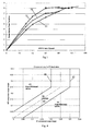
- Figure 3 illustrates an example of values of surge outlet flow function against HP compressor corrected speed for various bleed settings. Curves 31, 32 and 33 shows the surge outlet flow function for three different bleed settings of increasing amounts of bleed.
- the surge margin calculation module 24 therefore calculates, using the measured engine parameters, a value for the actual outlet flow function for each compressor and a value for the surge outlet flow function.
- the difference between the values of the flow functions (usually expressed as a percentage) is an estimate of the actual surge margin for that compressor.
- the current surge margin values are then input to a control signal generator 25 which generates engine control signals based on a control strategy that balances the potentially conflicting requirements of the two core compressors.
- the control signals are passed to an output 26 where they can be output to the various control systems of the engine.
- One output 26 is shown for clarity in Figure 2 but the skilled person will appreciate that there may be many outputs for different types of control system.
- output 26 is capable of outputting the relevant control signals it may also receive data or information from the various engine sub-systems, ie output 26 could connect to an engine control bus or the like.
- the various modules of controller 20 are illustrated for the purposes of explanation only and in some embodiments a suitable programmed processor or suitable logic circuitry may be arranged to calculate the surge margins, determine an appropriate control strategy and generate the necessary control signals.
- the control signals may comprise bleed valve control signals for controlling the bleed valves 12 and 13, ie for controlling the valve actuators, and also inlet guide vane control signals for controlling the variable inlet guide vanes of the IP compressor 6.
- Other control signals may additionally or alternatively be generated and the control signals may control any aspect of the engine variables that can be adjusted to regulate the surge margin.
- the controller is preferably operable to provide continuous bleed valve control, ie optimum setting of the bleed valves such that the overall requirements of the two compressors are addressed.
- This bleed valve control operates continuously and pre-emptively and thus regulates the surge margins for both compressors without the need for rapid reacting, high bandwidth hardware.
- the controller is also preferably operable to provide variable guide vane control, ie trimming control of the variable inlet guide vanes 11 shown in figure 1 .
- the variable guide vanes control may typically be applied during periods of engine transients and again the controller balances the overall needs of both compressors.
- the controller 20 implements an active regulation strategy based on balancing the requirements of the two compressors.
- the surge margins for each of the IP and HP compressors are plotted in a surge margin operating map.
- the surge margin operating map plots the surge margin for each compressor along one dimension.
- the surge margin operating map is two dimensional but were the surge margins for three or more distinct compressors to be determined the operating map would have three of more dimensions.
- the surge margin operating map is divided into a number of control domains for control of at least some of the engine variables.
- Figure 4 shows an example of a surge margin operating map and the control domains for control of bleed valves 12, ie the bleed valves located after the IP compressor and before the HP compressor.
- the surge margin for the IP compressor is plotted along the horizontal axis and the surge margin for the HP compressor is plotted along the vertical axis.
- the operating map is divided into three separate domains.
- a first domain 40, bounded by solid lines 41 and 42, is a no change domain.
- a second domain, 43, bounded by line 41 is an open bleed valves domain and a third domain, 44, is a close bleed valves domain.
- the position of the current operating point of the engine is plotted onto the surge margin operating map and, based on the domain into which the operating point falls, the appropriate action is taken. If the operating point falls within the no change domain 40 the current bleed valve setting for bleed valves 12 is maintained, whatever the current setting is. If the operating point moves into the open bleed valves domain 43 a control signal for opening the bleed valves is generated. If the operating point subsequently moves into the close bleed valves domain 44 a control signal is generated to close the bleed valves.
- boundary line 42 does not extend beyond a certain value of surge margin for the IP compressor this means that bleed valves are closed whenever the IP compressor has a sufficient surge margin.
- Domain 43 indicating that the bleed valves should be opened is arranged such that the bleed valves are only opened when the surge margin for the HP compressor is greater than that for the IP compressor, ie the IP compressor is closer to surge conditions and the balance of risk lies with opening the bleed valves.
- the no change domain is arranged such that when both compressors have low surge margins no action is taken to disturb the status quo, at least as regards bleed valves 12.
- the no change domain also provides a level of hysteresis in control of the bleed valves which can stabilise operation.
- control domains shown in Figure 4 is applicable to control of bleed valves located between the IP and HP compressors of a three shaft engine architecture but the particular values and/or relative placing of the domains will vary according to the particular engine.
- the placing of the domains on the surge margin operating map can be based on experimental data obtained during engine testing.
- the principle of an operating map as shown in figure 4 also allows for control of binary bleed valves.
- the actuators controlling the bleed valves are binary in nature in that a particular valve is either open or closed.
- the controller 20 shown in Figure 2 is capable of generating a control signal for individual control of the binary bleed valves in a set. Each bleed valve in a set may be opened or closed individually or some bleed valves may be opened or closed together in subsets if necessary. By opening only some of the bleed valves in a set the amount of bleed achieved can be controlled.
- the Euclidean distance of the current operating point from the nearest boundary, lines 41 or 42, may be determined and input to an integrator module 27.
- a threshold value is defined for each individual bleed valve, or subset, within the set. As the integrator state reaches each threshold value the associated bleed valve is toggled.
- the integrator module may be implemented in hardware or software within the controller.
- control domains 40, 43 and 44 are continuous. For some control systems in some engine designs it is possible that there may be discrete domains that have the same control operation.
- the controller 20 therefore provides continuous regulation of the surge margin in a gas turbine engine comprising two or more compressors and balances the potentially competing requirements of the compressors.
- the controller may be implemented within existing gas turbine control systems and use existing measured engine parameters to directly infer a surge margin for each of two or more compressors.
- Engine variables such as bleed valve settings can be continually adjusted as required to provide pre-emptive regulation of the surge margin for each compressor which is monitored, thus avoiding the need for very fast acting hardware.
Landscapes
- Engineering & Computer Science (AREA)
- Mechanical Engineering (AREA)
- General Engineering & Computer Science (AREA)
- Chemical & Material Sciences (AREA)
- Combustion & Propulsion (AREA)
- Life Sciences & Earth Sciences (AREA)
- Sustainable Development (AREA)
- Physics & Mathematics (AREA)
- Fluid Mechanics (AREA)
- Control Of Positive-Displacement Air Blowers (AREA)
- Control Of Turbines (AREA)
Applications Claiming Priority (1)
| Application Number | Priority Date | Filing Date | Title |
|---|---|---|---|
| GB0915616A GB0915616D0 (en) | 2009-09-08 | 2009-09-08 | Surge margin regulation |
Publications (3)
| Publication Number | Publication Date |
|---|---|
| EP2292909A2 true EP2292909A2 (de) | 2011-03-09 |
| EP2292909A3 EP2292909A3 (de) | 2017-06-07 |
| EP2292909B1 EP2292909B1 (de) | 2018-05-16 |
Family
ID=41203325
Family Applications (1)
| Application Number | Title | Priority Date | Filing Date |
|---|---|---|---|
| EP10170935.0A Active EP2292909B1 (de) | 2009-09-08 | 2010-07-27 | Regelung des Pumpgrenzenabstands |
Country Status (4)
| Country | Link |
|---|---|
| US (1) | US8661832B2 (de) |
| EP (1) | EP2292909B1 (de) |
| JP (1) | JP5552002B2 (de) |
| GB (1) | GB0915616D0 (de) |
Cited By (1)
| Publication number | Priority date | Publication date | Assignee | Title |
|---|---|---|---|---|
| EP3351770A1 (de) * | 2017-01-23 | 2018-07-25 | Doosan Heavy Industries & Construction Co., Ltd. | Verfahren zur steuerung der pumpgrenze einer gasturbine und abblasvorrichtung für eine gasturbine |
Families Citing this family (31)
| Publication number | Priority date | Publication date | Assignee | Title |
|---|---|---|---|---|
| US20120167587A1 (en) * | 2010-12-30 | 2012-07-05 | Robert Earl Clark | Gas turbine engine with bleed air system |
| WO2013081840A1 (en) | 2011-12-01 | 2013-06-06 | Carrier Corporation | Surge prevention during startup of a chiller compressor |
| US9382010B2 (en) | 2012-07-12 | 2016-07-05 | Pratt & Whitney Canada Corp. | Aircraft power outtake management |
| US9677566B2 (en) | 2012-10-09 | 2017-06-13 | Carrier Corporation | Centrifugal compressor inlet guide vane control |
| US9611752B2 (en) * | 2013-03-15 | 2017-04-04 | General Electric Company | Compressor start bleed system for a turbine system and method of controlling a compressor start bleed system |
| US10144519B2 (en) * | 2014-10-24 | 2018-12-04 | United Technologies Corporation | Compressor bleed air supply for an aircraft environmental control system |
| US9777642B2 (en) | 2014-11-21 | 2017-10-03 | General Electric Company | Gas turbine engine and method of assembling the same |
| CN106151085B (zh) * | 2015-04-09 | 2019-12-03 | 开利公司 | 流体设备喘振监控方法和制冷系统 |
| US10156190B2 (en) | 2015-05-20 | 2018-12-18 | Honeywell International Inc. | Gas turbine engine uncontrolled high thrust accommodation system and method |
| KR101695125B1 (ko) | 2016-01-11 | 2017-01-10 | 두산중공업 주식회사 | 터빈의 다단 실링 구조 |
| US10794281B2 (en) * | 2016-02-02 | 2020-10-06 | General Electric Company | Gas turbine engine having instrumented airflow path components |
| US11073090B2 (en) | 2016-03-30 | 2021-07-27 | General Electric Company | Valved airflow passage assembly for adjusting airflow distortion in gas turbine engine |
| US10753278B2 (en) * | 2016-03-30 | 2020-08-25 | General Electric Company | Translating inlet for adjusting airflow distortion in gas turbine engine |
| US10273884B2 (en) | 2016-06-09 | 2019-04-30 | Hamilton Sundstrand Corporation | Altitude compensating bleed valve |
| JP6639338B2 (ja) * | 2016-07-11 | 2020-02-05 | 三菱日立パワーシステムズ株式会社 | ガスタービン及びガスタービンの運転方法 |
| US20180163736A1 (en) * | 2016-12-09 | 2018-06-14 | General Electric Company | Systems and methods for operating a compression system |
| EP4194676A1 (de) | 2017-05-25 | 2023-06-14 | Ge Avio S.r.l. | Steuerung eines verdichters eines turbinenmotors |
| US10794272B2 (en) * | 2018-02-19 | 2020-10-06 | General Electric Company | Axial and centrifugal compressor |
| KR102130839B1 (ko) * | 2018-03-27 | 2020-07-07 | 두산중공업 주식회사 | 가스터빈 및 이의 제어방법 |
| GB201807840D0 (en) * | 2018-05-15 | 2018-06-27 | Rolls Royce Plc | Gas turbine engine |
| GB201808852D0 (en) * | 2018-05-31 | 2018-07-18 | Rolls Royce Plc | Gas turbine engine |
| JP7157589B2 (ja) * | 2018-08-13 | 2022-10-20 | 三菱重工サーマルシステムズ株式会社 | 制御装置、冷凍機、制御方法及び異常検出方法 |
| US20210180523A1 (en) * | 2019-12-13 | 2021-06-17 | Pratt & Whitney Canada Corp. | Systems and methods for operating an engine having variable geometry mechanisms |
| DE102020102332A1 (de) * | 2020-01-30 | 2021-08-05 | Rolls-Royce Deutschland Ltd & Co Kg | Sensorvorrichtung und Messverfahren |
| US11391288B2 (en) | 2020-09-09 | 2022-07-19 | General Electric Company | System and method for operating a compressor assembly |
| US11554874B2 (en) * | 2020-10-02 | 2023-01-17 | Pratt & Whitney Canada Corp. | Method and system for governing an engine at low power |
| US12025060B2 (en) | 2021-05-19 | 2024-07-02 | Pratt & Whitney Canada Corp. | Method and system for operating an engine to prevent high power engine surges |
| US12196141B2 (en) * | 2023-04-19 | 2025-01-14 | Honeywell International Inc. | Systems and methods with distributed bleed for gas turbine engine compressor stabilization |
| US20240352892A1 (en) * | 2023-04-21 | 2024-10-24 | Raytheon Technologies Corporation | Multi-valve modulated core ventilation |
| US12312997B2 (en) | 2023-09-08 | 2025-05-27 | General Electric Company | Turbine engine having a bleed system |
| US12276229B2 (en) * | 2023-09-08 | 2025-04-15 | General Electric Company | Method of operating a turbine engine having a bleed system |
Citations (2)
| Publication number | Priority date | Publication date | Assignee | Title |
|---|---|---|---|---|
| US20020161550A1 (en) | 2001-04-17 | 2002-10-31 | Sanjay Bharadwaj | Method and apparatus for continuous prediction, monitoring and control of compressor health via detection of precursors to rotating stall and surge |
| US20080155989A1 (en) | 2006-12-28 | 2008-07-03 | General Electric Company | Operating line control of a compression system with flow recirculation |
Family Cites Families (11)
| Publication number | Priority date | Publication date | Assignee | Title |
|---|---|---|---|---|
| US2785848A (en) * | 1953-08-28 | 1957-03-19 | Rolls Royce | Gas turbine engines with speed control mechanism |
| WO1994003862A1 (en) * | 1992-08-10 | 1994-02-17 | Dow Deutschland Inc. | Process and device for monitoring and for controlling of a compressor |
| GB2273316B (en) | 1992-12-12 | 1996-02-28 | Rolls Royce Plc | Bleed valve control |
| WO1997000381A1 (en) * | 1994-12-14 | 1997-01-03 | United Technologies Corporation | Compressor stall and surge control using airflow asymmetry measurement |
| US6059522A (en) * | 1996-04-17 | 2000-05-09 | United Technologies Corporation | Compressor stall diagnostics and avoidance |
| US6098010A (en) * | 1997-11-20 | 2000-08-01 | The Regents Of The University Of California | Method and apparatus for predicting and stabilizing compressor stall |
| JP4705732B2 (ja) * | 2000-05-25 | 2011-06-22 | 本田技研工業株式会社 | 航空機用ガスタービン・エンジンのサージ検出装置 |
| WO2003044353A1 (en) * | 2001-11-15 | 2003-05-30 | Goodrich Pump & Engine Control Systems, Inc. | Method and apparatus for adaptive acceleration schedules in gas turbine engine control systems |
| US6755025B2 (en) * | 2002-07-23 | 2004-06-29 | Pratt & Whitney Canada Corp. | Pneumatic compressor bleed valve |
| GB0523337D0 (en) * | 2005-11-16 | 2005-12-28 | Rolls Royce Plc | Engine arrangements and control |
| JP2009057955A (ja) * | 2007-08-29 | 2009-03-19 | Isamu Nemoto | 超音速機用インタータービン・バイパス可変サイクルエンジン |
-
2009
- 2009-09-08 GB GB0915616A patent/GB0915616D0/en not_active Ceased
-
2010
- 2010-07-27 US US12/844,146 patent/US8661832B2/en active Active
- 2010-07-27 EP EP10170935.0A patent/EP2292909B1/de active Active
- 2010-09-07 JP JP2010199674A patent/JP5552002B2/ja not_active Expired - Fee Related
Patent Citations (2)
| Publication number | Priority date | Publication date | Assignee | Title |
|---|---|---|---|---|
| US20020161550A1 (en) | 2001-04-17 | 2002-10-31 | Sanjay Bharadwaj | Method and apparatus for continuous prediction, monitoring and control of compressor health via detection of precursors to rotating stall and surge |
| US20080155989A1 (en) | 2006-12-28 | 2008-07-03 | General Electric Company | Operating line control of a compression system with flow recirculation |
Cited By (4)
| Publication number | Priority date | Publication date | Assignee | Title |
|---|---|---|---|---|
| EP3351770A1 (de) * | 2017-01-23 | 2018-07-25 | Doosan Heavy Industries & Construction Co., Ltd. | Verfahren zur steuerung der pumpgrenze einer gasturbine und abblasvorrichtung für eine gasturbine |
| CN108343513A (zh) * | 2017-01-23 | 2018-07-31 | 斗山重工业建设有限公司 | 燃气轮机的喘振裕度控制方法和燃气轮机的抽气装置 |
| CN108343513B (zh) * | 2017-01-23 | 2020-06-09 | 斗山重工业建设有限公司 | 燃气轮机的喘振裕度控制方法和燃气轮机的抽气装置 |
| US10859002B2 (en) | 2017-01-23 | 2020-12-08 | DOOSAN Heavy Industries Construction Co., LTD | Method for controlling surge margin of gas turbine and extraction device for gas turbine |
Also Published As
| Publication number | Publication date |
|---|---|
| JP2011058494A (ja) | 2011-03-24 |
| JP5552002B2 (ja) | 2014-07-16 |
| US20110056210A1 (en) | 2011-03-10 |
| EP2292909A3 (de) | 2017-06-07 |
| US8661832B2 (en) | 2014-03-04 |
| EP2292909B1 (de) | 2018-05-16 |
| GB0915616D0 (en) | 2009-10-07 |
Similar Documents
| Publication | Publication Date | Title |
|---|---|---|
| EP2292909B1 (de) | Regelung des Pumpgrenzenabstands | |
| US7762084B2 (en) | System and method for controlling the working line position in a gas turbine engine compressor | |
| US4242864A (en) | Integrated control system for a gas turbine engine | |
| JP5662697B2 (ja) | ガスタービンの制御及び運転に関する方法 | |
| EP2148044B1 (de) | Gasturbinenmotorkompressor mit variabler Statorschaufelanordnung | |
| EP2955334B1 (de) | Verfahren und vorrichtung zur steuerung eines verdichters eines gasturbinenmotors | |
| EP1444428B1 (de) | Verfahren und vorrichtung zur vermeidung des pumpens in einer gasturbine | |
| US10006374B2 (en) | Control of a gas turbine engine | |
| CN106907345A (zh) | 用于根据发动机健康的失速裕度调节的方法和系统 | |
| EP1312780A2 (de) | Kraftstoffregelungssystem für Gasturbinen | |
| EP2778376B1 (de) | System und Verfahren zur Motorübergangsleistungsreaktion | |
| EP1788223B1 (de) | Turbinentriebwerksanordnungen und Regelung | |
| EP3530929A1 (de) | Gasturbinentriebwerkverdichterverwaltungssystem | |
| US12170500B2 (en) | Active stability control of compression systems utilizing electric machines | |
| US20180230853A1 (en) | Method for limiting the core engine speed of a gas turbine engine during icing conditions | |
| CA1086512A (en) | Bleed valve control system | |
| JP5546541B2 (ja) | ガスタービンおよびその運転方法 | |
| EP3351771B1 (de) | Gasturbinenmotorbrennstoffsteuerungssystem und -verfahren | |
| JP5843515B2 (ja) | ガスタービン、ガスタービン制御装置、および発電システム | |
| CN113544373A (zh) | 用于调节涡轮机排气温度的方法 | |
| EP3913201B1 (de) | Geschwindigkeitsbegrenzung für leistungsturbinenregelung und -schutz in einem gasturbinentriebwerk | |
| EP4553310A1 (de) | Referenzbeschleunigungssteuerungsarchitektur für gemischte n-punkt- und verhältniseinheit für gasturbinenmotor | |
| EP4151847A1 (de) | System und verfahren zur nicht-modellbasierten steuerung unter verwendung eines turbinenausgangs-machzahl-surrogats | |
| CN113646521B (zh) | 用控制饱和度管理控制涡轮发动机的方法和系统 | |
| Martis et al. | Engine Performance Improvement by Controlling the Low Pressure Compressor Working Line |
Legal Events
| Date | Code | Title | Description |
|---|---|---|---|
| PUAI | Public reference made under article 153(3) epc to a published international application that has entered the european phase |
Free format text: ORIGINAL CODE: 0009012 |
|
| AK | Designated contracting states |
Kind code of ref document: A2 Designated state(s): AL AT BE BG CH CY CZ DE DK EE ES FI FR GB GR HR HU IE IS IT LI LT LU LV MC MK MT NL NO PL PT RO SE SI SK SM TR |
|
| AX | Request for extension of the european patent |
Extension state: BA ME RS |
|
| RAP1 | Party data changed (applicant data changed or rights of an application transferred) |
Owner name: ROLLS-ROYCE PLC |
|
| PUAL | Search report despatched |
Free format text: ORIGINAL CODE: 0009013 |
|
| AK | Designated contracting states |
Kind code of ref document: A3 Designated state(s): AL AT BE BG CH CY CZ DE DK EE ES FI FR GB GR HR HU IE IS IT LI LT LU LV MC MK MT NL NO PL PT RO SE SI SK SM TR |
|
| AX | Request for extension of the european patent |
Extension state: BA ME RS |
|
| RIC1 | Information provided on ipc code assigned before grant |
Ipc: F04D 27/02 20060101ALI20170503BHEP Ipc: F02C 9/18 20060101AFI20170503BHEP |
|
| PUAL | Search report despatched |
Free format text: ORIGINAL CODE: 0009013 |
|
| STAA | Information on the status of an ep patent application or granted ep patent |
Free format text: STATUS: REQUEST FOR EXAMINATION WAS MADE |
|
| 17P | Request for examination filed |
Effective date: 20171113 |
|
| RBV | Designated contracting states (corrected) |
Designated state(s): AL AT BE BG CH CY CZ DE DK EE ES FI FR GB GR HR HU IE IS IT LI LT LU LV MC MK MT NL NO PL PT RO SE SI SK SM TR |
|
| RIC1 | Information provided on ipc code assigned before grant |
Ipc: F04D 27/02 20060101ALI20180209BHEP Ipc: F02C 9/18 20060101AFI20180209BHEP |
|
| GRAP | Despatch of communication of intention to grant a patent |
Free format text: ORIGINAL CODE: EPIDOSNIGR1 |
|
| STAA | Information on the status of an ep patent application or granted ep patent |
Free format text: STATUS: GRANT OF PATENT IS INTENDED |
|
| GRAS | Grant fee paid |
Free format text: ORIGINAL CODE: EPIDOSNIGR3 |
|
| GRAA | (expected) grant |
Free format text: ORIGINAL CODE: 0009210 |
|
| STAA | Information on the status of an ep patent application or granted ep patent |
Free format text: STATUS: THE PATENT HAS BEEN GRANTED |
|
| INTG | Intention to grant announced |
Effective date: 20180321 |
|
| AK | Designated contracting states |
Kind code of ref document: B1 Designated state(s): AL AT BE BG CH CY CZ DE DK EE ES FI FR GB GR HR HU IE IS IT LI LT LU LV MC MK MT NL NO PL PT RO SE SI SK SM TR |
|
| REG | Reference to a national code |
Ref country code: GB Ref legal event code: FG4D |
|
| REG | Reference to a national code |
Ref country code: CH Ref legal event code: EP |
|
| REG | Reference to a national code |
Ref country code: IE Ref legal event code: FG4D |
|
| REG | Reference to a national code |
Ref country code: DE Ref legal event code: R096 Ref document number: 602010050589 Country of ref document: DE |
|
| REG | Reference to a national code |
Ref country code: AT Ref legal event code: REF Ref document number: 999802 Country of ref document: AT Kind code of ref document: T Effective date: 20180615 |
|
| REG | Reference to a national code |
Ref country code: FR Ref legal event code: PLFP Year of fee payment: 9 |
|
| REG | Reference to a national code |
Ref country code: NL Ref legal event code: MP Effective date: 20180516 |
|
| REG | Reference to a national code |
Ref country code: LT Ref legal event code: MG4D |
|
| PG25 | Lapsed in a contracting state [announced via postgrant information from national office to epo] |
Ref country code: BG Free format text: LAPSE BECAUSE OF FAILURE TO SUBMIT A TRANSLATION OF THE DESCRIPTION OR TO PAY THE FEE WITHIN THE PRESCRIBED TIME-LIMIT Effective date: 20180816 Ref country code: LT Free format text: LAPSE BECAUSE OF FAILURE TO SUBMIT A TRANSLATION OF THE DESCRIPTION OR TO PAY THE FEE WITHIN THE PRESCRIBED TIME-LIMIT Effective date: 20180516 Ref country code: ES Free format text: LAPSE BECAUSE OF FAILURE TO SUBMIT A TRANSLATION OF THE DESCRIPTION OR TO PAY THE FEE WITHIN THE PRESCRIBED TIME-LIMIT Effective date: 20180516 Ref country code: FI Free format text: LAPSE BECAUSE OF FAILURE TO SUBMIT A TRANSLATION OF THE DESCRIPTION OR TO PAY THE FEE WITHIN THE PRESCRIBED TIME-LIMIT Effective date: 20180516 Ref country code: NO Free format text: LAPSE BECAUSE OF FAILURE TO SUBMIT A TRANSLATION OF THE DESCRIPTION OR TO PAY THE FEE WITHIN THE PRESCRIBED TIME-LIMIT Effective date: 20180816 Ref country code: SE Free format text: LAPSE BECAUSE OF FAILURE TO SUBMIT A TRANSLATION OF THE DESCRIPTION OR TO PAY THE FEE WITHIN THE PRESCRIBED TIME-LIMIT Effective date: 20180516 |
|
| PG25 | Lapsed in a contracting state [announced via postgrant information from national office to epo] |
Ref country code: HR Free format text: LAPSE BECAUSE OF FAILURE TO SUBMIT A TRANSLATION OF THE DESCRIPTION OR TO PAY THE FEE WITHIN THE PRESCRIBED TIME-LIMIT Effective date: 20180516 Ref country code: GR Free format text: LAPSE BECAUSE OF FAILURE TO SUBMIT A TRANSLATION OF THE DESCRIPTION OR TO PAY THE FEE WITHIN THE PRESCRIBED TIME-LIMIT Effective date: 20180817 Ref country code: LV Free format text: LAPSE BECAUSE OF FAILURE TO SUBMIT A TRANSLATION OF THE DESCRIPTION OR TO PAY THE FEE WITHIN THE PRESCRIBED TIME-LIMIT Effective date: 20180516 Ref country code: NL Free format text: LAPSE BECAUSE OF FAILURE TO SUBMIT A TRANSLATION OF THE DESCRIPTION OR TO PAY THE FEE WITHIN THE PRESCRIBED TIME-LIMIT Effective date: 20180516 |
|
| REG | Reference to a national code |
Ref country code: AT Ref legal event code: MK05 Ref document number: 999802 Country of ref document: AT Kind code of ref document: T Effective date: 20180516 |
|
| PG25 | Lapsed in a contracting state [announced via postgrant information from national office to epo] |
Ref country code: SK Free format text: LAPSE BECAUSE OF FAILURE TO SUBMIT A TRANSLATION OF THE DESCRIPTION OR TO PAY THE FEE WITHIN THE PRESCRIBED TIME-LIMIT Effective date: 20180516 Ref country code: RO Free format text: LAPSE BECAUSE OF FAILURE TO SUBMIT A TRANSLATION OF THE DESCRIPTION OR TO PAY THE FEE WITHIN THE PRESCRIBED TIME-LIMIT Effective date: 20180516 Ref country code: PL Free format text: LAPSE BECAUSE OF FAILURE TO SUBMIT A TRANSLATION OF THE DESCRIPTION OR TO PAY THE FEE WITHIN THE PRESCRIBED TIME-LIMIT Effective date: 20180516 Ref country code: CZ Free format text: LAPSE BECAUSE OF FAILURE TO SUBMIT A TRANSLATION OF THE DESCRIPTION OR TO PAY THE FEE WITHIN THE PRESCRIBED TIME-LIMIT Effective date: 20180516 Ref country code: AT Free format text: LAPSE BECAUSE OF FAILURE TO SUBMIT A TRANSLATION OF THE DESCRIPTION OR TO PAY THE FEE WITHIN THE PRESCRIBED TIME-LIMIT Effective date: 20180516 Ref country code: DK Free format text: LAPSE BECAUSE OF FAILURE TO SUBMIT A TRANSLATION OF THE DESCRIPTION OR TO PAY THE FEE WITHIN THE PRESCRIBED TIME-LIMIT Effective date: 20180516 Ref country code: EE Free format text: LAPSE BECAUSE OF FAILURE TO SUBMIT A TRANSLATION OF THE DESCRIPTION OR TO PAY THE FEE WITHIN THE PRESCRIBED TIME-LIMIT Effective date: 20180516 |
|
| REG | Reference to a national code |
Ref country code: DE Ref legal event code: R097 Ref document number: 602010050589 Country of ref document: DE |
|
| PG25 | Lapsed in a contracting state [announced via postgrant information from national office to epo] |
Ref country code: SM Free format text: LAPSE BECAUSE OF FAILURE TO SUBMIT A TRANSLATION OF THE DESCRIPTION OR TO PAY THE FEE WITHIN THE PRESCRIBED TIME-LIMIT Effective date: 20180516 Ref country code: IT Free format text: LAPSE BECAUSE OF FAILURE TO SUBMIT A TRANSLATION OF THE DESCRIPTION OR TO PAY THE FEE WITHIN THE PRESCRIBED TIME-LIMIT Effective date: 20180516 |
|
| REG | Reference to a national code |
Ref country code: CH Ref legal event code: PL |
|
| PLBE | No opposition filed within time limit |
Free format text: ORIGINAL CODE: 0009261 |
|
| STAA | Information on the status of an ep patent application or granted ep patent |
Free format text: STATUS: NO OPPOSITION FILED WITHIN TIME LIMIT |
|
| PG25 | Lapsed in a contracting state [announced via postgrant information from national office to epo] |
Ref country code: MC Free format text: LAPSE BECAUSE OF FAILURE TO SUBMIT A TRANSLATION OF THE DESCRIPTION OR TO PAY THE FEE WITHIN THE PRESCRIBED TIME-LIMIT Effective date: 20180516 Ref country code: LU Free format text: LAPSE BECAUSE OF NON-PAYMENT OF DUE FEES Effective date: 20180727 |
|
| REG | Reference to a national code |
Ref country code: BE Ref legal event code: MM Effective date: 20180731 |
|
| 26N | No opposition filed |
Effective date: 20190219 |
|
| PG25 | Lapsed in a contracting state [announced via postgrant information from national office to epo] |
Ref country code: CH Free format text: LAPSE BECAUSE OF NON-PAYMENT OF DUE FEES Effective date: 20180731 Ref country code: LI Free format text: LAPSE BECAUSE OF NON-PAYMENT OF DUE FEES Effective date: 20180731 |
|
| REG | Reference to a national code |
Ref country code: IE Ref legal event code: MM4A |
|
| PG25 | Lapsed in a contracting state [announced via postgrant information from national office to epo] |
Ref country code: BE Free format text: LAPSE BECAUSE OF NON-PAYMENT OF DUE FEES Effective date: 20180731 Ref country code: SI Free format text: LAPSE BECAUSE OF FAILURE TO SUBMIT A TRANSLATION OF THE DESCRIPTION OR TO PAY THE FEE WITHIN THE PRESCRIBED TIME-LIMIT Effective date: 20180516 |
|
| PG25 | Lapsed in a contracting state [announced via postgrant information from national office to epo] |
Ref country code: IE Free format text: LAPSE BECAUSE OF NON-PAYMENT OF DUE FEES Effective date: 20180727 |
|
| PG25 | Lapsed in a contracting state [announced via postgrant information from national office to epo] |
Ref country code: AL Free format text: LAPSE BECAUSE OF FAILURE TO SUBMIT A TRANSLATION OF THE DESCRIPTION OR TO PAY THE FEE WITHIN THE PRESCRIBED TIME-LIMIT Effective date: 20180516 |
|
| PG25 | Lapsed in a contracting state [announced via postgrant information from national office to epo] |
Ref country code: MT Free format text: LAPSE BECAUSE OF NON-PAYMENT OF DUE FEES Effective date: 20180727 |
|
| PG25 | Lapsed in a contracting state [announced via postgrant information from national office to epo] |
Ref country code: TR Free format text: LAPSE BECAUSE OF FAILURE TO SUBMIT A TRANSLATION OF THE DESCRIPTION OR TO PAY THE FEE WITHIN THE PRESCRIBED TIME-LIMIT Effective date: 20180516 |
|
| PG25 | Lapsed in a contracting state [announced via postgrant information from national office to epo] |
Ref country code: HU Free format text: LAPSE BECAUSE OF FAILURE TO SUBMIT A TRANSLATION OF THE DESCRIPTION OR TO PAY THE FEE WITHIN THE PRESCRIBED TIME-LIMIT; INVALID AB INITIO Effective date: 20100727 Ref country code: PT Free format text: LAPSE BECAUSE OF FAILURE TO SUBMIT A TRANSLATION OF THE DESCRIPTION OR TO PAY THE FEE WITHIN THE PRESCRIBED TIME-LIMIT Effective date: 20180516 |
|
| PG25 | Lapsed in a contracting state [announced via postgrant information from national office to epo] |
Ref country code: MK Free format text: LAPSE BECAUSE OF NON-PAYMENT OF DUE FEES Effective date: 20180516 Ref country code: CY Free format text: LAPSE BECAUSE OF FAILURE TO SUBMIT A TRANSLATION OF THE DESCRIPTION OR TO PAY THE FEE WITHIN THE PRESCRIBED TIME-LIMIT Effective date: 20180516 |
|
| PG25 | Lapsed in a contracting state [announced via postgrant information from national office to epo] |
Ref country code: IS Free format text: LAPSE BECAUSE OF FAILURE TO SUBMIT A TRANSLATION OF THE DESCRIPTION OR TO PAY THE FEE WITHIN THE PRESCRIBED TIME-LIMIT Effective date: 20180916 |
|
| P01 | Opt-out of the competence of the unified patent court (upc) registered |
Effective date: 20230528 |
|
| PGFP | Annual fee paid to national office [announced via postgrant information from national office to epo] |
Ref country code: DE Payment date: 20250728 Year of fee payment: 16 |
|
| PGFP | Annual fee paid to national office [announced via postgrant information from national office to epo] |
Ref country code: GB Payment date: 20250722 Year of fee payment: 16 |
|
| PGFP | Annual fee paid to national office [announced via postgrant information from national office to epo] |
Ref country code: FR Payment date: 20250725 Year of fee payment: 16 |