EP2292501A1 - Device for fixing accessories in a motorcycle, in particular for a windshield - Google Patents
Device for fixing accessories in a motorcycle, in particular for a windshield Download PDFInfo
- Publication number
- EP2292501A1 EP2292501A1 EP10168678A EP10168678A EP2292501A1 EP 2292501 A1 EP2292501 A1 EP 2292501A1 EP 10168678 A EP10168678 A EP 10168678A EP 10168678 A EP10168678 A EP 10168678A EP 2292501 A1 EP2292501 A1 EP 2292501A1
- Authority
- EP
- European Patent Office
- Prior art keywords
- shaft
- sleeve element
- sleeve
- motorcycle
- elastic spacer
- Prior art date
- Legal status (The legal status is an assumption and is not a legal conclusion. Google has not performed a legal analysis and makes no representation as to the accuracy of the status listed.)
- Granted
Links
Images


Classifications
-
- B—PERFORMING OPERATIONS; TRANSPORTING
- B62—LAND VEHICLES FOR TRAVELLING OTHERWISE THAN ON RAILS
- B62K—CYCLES; CYCLE FRAMES; CYCLE STEERING DEVICES; RIDER-OPERATED TERMINAL CONTROLS SPECIALLY ADAPTED FOR CYCLES; CYCLE AXLE SUSPENSIONS; CYCLE SIDECARS, FORECARS, OR THE LIKE
- B62K19/00—Cycle frames
- B62K19/30—Frame parts shaped to receive other cycle parts or accessories
-
- B—PERFORMING OPERATIONS; TRANSPORTING
- B62—LAND VEHICLES FOR TRAVELLING OTHERWISE THAN ON RAILS
- B62J—CYCLE SADDLES OR SEATS; AUXILIARY DEVICES OR ACCESSORIES SPECIALLY ADAPTED TO CYCLES AND NOT OTHERWISE PROVIDED FOR, e.g. ARTICLE CARRIERS OR CYCLE PROTECTORS
- B62J11/00—Supporting arrangements specially adapted for fastening specific devices to cycles, e.g. supports for attaching maps
-
- B—PERFORMING OPERATIONS; TRANSPORTING
- B62—LAND VEHICLES FOR TRAVELLING OTHERWISE THAN ON RAILS
- B62J—CYCLE SADDLES OR SEATS; AUXILIARY DEVICES OR ACCESSORIES SPECIALLY ADAPTED TO CYCLES AND NOT OTHERWISE PROVIDED FOR, e.g. ARTICLE CARRIERS OR CYCLE PROTECTORS
- B62J17/00—Weather guards for riders; Fairings or stream-lining parts not otherwise provided for
- B62J17/02—Weather guards for riders; Fairings or stream-lining parts not otherwise provided for shielding only the rider's front
- B62J17/04—Windscreens
-
- F—MECHANICAL ENGINEERING; LIGHTING; HEATING; WEAPONS; BLASTING
- F16—ENGINEERING ELEMENTS AND UNITS; GENERAL MEASURES FOR PRODUCING AND MAINTAINING EFFECTIVE FUNCTIONING OF MACHINES OR INSTALLATIONS; THERMAL INSULATION IN GENERAL
- F16B—DEVICES FOR FASTENING OR SECURING CONSTRUCTIONAL ELEMENTS OR MACHINE PARTS TOGETHER, e.g. NAILS, BOLTS, CIRCLIPS, CLAMPS, CLIPS OR WEDGES; JOINTS OR JOINTING
- F16B41/00—Measures against loss of bolts, nuts, or pins; Measures against unauthorised operation of bolts, nuts or pins
- F16B41/002—Measures against loss of bolts, nuts or pins
-
- F—MECHANICAL ENGINEERING; LIGHTING; HEATING; WEAPONS; BLASTING
- F16—ENGINEERING ELEMENTS AND UNITS; GENERAL MEASURES FOR PRODUCING AND MAINTAINING EFFECTIVE FUNCTIONING OF MACHINES OR INSTALLATIONS; THERMAL INSULATION IN GENERAL
- F16B—DEVICES FOR FASTENING OR SECURING CONSTRUCTIONAL ELEMENTS OR MACHINE PARTS TOGETHER, e.g. NAILS, BOLTS, CIRCLIPS, CLAMPS, CLIPS OR WEDGES; JOINTS OR JOINTING
- F16B7/00—Connections of rods or tubes, e.g. of non-circular section, mutually, including resilient connections
- F16B7/10—Telescoping systems
- F16B7/14—Telescoping systems locking in intermediate non-discrete positions
- F16B7/1445—Telescoping systems locking in intermediate non-discrete positions with a rubber bushing gripping inside the outer telescoping member by a radial expansion due to its axial compression
-
- Y—GENERAL TAGGING OF NEW TECHNOLOGICAL DEVELOPMENTS; GENERAL TAGGING OF CROSS-SECTIONAL TECHNOLOGIES SPANNING OVER SEVERAL SECTIONS OF THE IPC; TECHNICAL SUBJECTS COVERED BY FORMER USPC CROSS-REFERENCE ART COLLECTIONS [XRACs] AND DIGESTS
- Y10—TECHNICAL SUBJECTS COVERED BY FORMER USPC
- Y10T—TECHNICAL SUBJECTS COVERED BY FORMER US CLASSIFICATION
- Y10T403/00—Joints and connections
- Y10T403/70—Interfitted members
-
- Y—GENERAL TAGGING OF NEW TECHNOLOGICAL DEVELOPMENTS; GENERAL TAGGING OF CROSS-SECTIONAL TECHNOLOGIES SPANNING OVER SEVERAL SECTIONS OF THE IPC; TECHNICAL SUBJECTS COVERED BY FORMER USPC CROSS-REFERENCE ART COLLECTIONS [XRACs] AND DIGESTS
- Y10—TECHNICAL SUBJECTS COVERED BY FORMER USPC
- Y10T—TECHNICAL SUBJECTS COVERED BY FORMER US CLASSIFICATION
- Y10T403/00—Joints and connections
- Y10T403/70—Interfitted members
- Y10T403/7041—Interfitted members including set screw
-
- Y—GENERAL TAGGING OF NEW TECHNOLOGICAL DEVELOPMENTS; GENERAL TAGGING OF CROSS-SECTIONAL TECHNOLOGIES SPANNING OVER SEVERAL SECTIONS OF THE IPC; TECHNICAL SUBJECTS COVERED BY FORMER USPC CROSS-REFERENCE ART COLLECTIONS [XRACs] AND DIGESTS
- Y10—TECHNICAL SUBJECTS COVERED BY FORMER USPC
- Y10T—TECHNICAL SUBJECTS COVERED BY FORMER US CLASSIFICATION
- Y10T403/00—Joints and connections
- Y10T403/70—Interfitted members
- Y10T403/7047—Radially interposed shim or bushing
- Y10T403/7051—Wedging or camming
- Y10T403/7052—Engaged by axial movement
- Y10T403/7056—Threaded actuator
Definitions
- the present invention relates to a device for fixing accessories in a motorcycle, in particular for a windshield.
- hybrid vehicles that combine the peculiarities of motorcycles, in terms of handiness, with the stability of four-wheeled vehicles.
- Such “hybrid” vehicles are represented, for example, by the three-wheeled vehicles provided with two front steering wheels, which can be driven as a motorbike (that is, they are laterally tilting on a curve) while offering the usual stability of four-wheeled vehicles.
- motorcycle refers to both traditional two-wheeled vehicles and to the above "hybrid” vehicles.
- fixing devices are used for positioning accessories, such as for example a windshield, on board of a motorcycle.
- These fixing devices of the known type usually consist of conical couplings associated, on the one side, to a portion of the motorcycle, such as the handlebar, through stud bolts or bolts and, on the other side, to the windshield by sleeve elements, which are constrainable through bolts as well.
- fixing devices are used which consist of a plurality of component parts associable by one or more bolts.
- the fixing devices are generally provided with reversible junction means, such as nuts, levers or others, which allow easily removing the accessory from the motorcycle and applying it back again to the same according to the needs. If the required tightening torque is not applied to the above reversible junction means, the accessory could accidentally detach from the motorcycle, with clear problems in terms of safety.
- the object of the present invention therefore is to provide a fixing device for accessories in a motorcycle, in particular for a windshield, capable of preventing accidental detachment of the accessory from the motorcycle also in the presence of loosening within the same fixing device.
- Another object of the invention is to provide a fixing device for accessories in a motorcycle capable of minimising the aesthetic impact of the same fixing device on the motorcycle.
- Yet another object of the invention is to provide a fixing device for accessories in a motorcycle the assembly operations whereof are simple and quick as it happens with the fixing devices of the prior art.
- At least one tubular element or sleeve 18 is steadily attached, for example by welding, to the handlebar 16.
- the free end of the shaft 12 is insertable, that is, the end whereon windshield 14 is not attached, through the interposition of at least one elastic spacer element 20.
- the elastic spacer element 20 is made as a sleeve and at a first end thereof (that facing the free end of the shaft 12), it is refrained by fastening elements from axially sliding, consisting of a screw 22 with a hexagonal head and a relevant elastic washer 24. Screw 22 is configured to be inserted in a threaded blind hole 26 made axially at the free end of shaft 12.
- the elastic spacer element 20 is therefore placed in contact, at the end thereof opposite that facing the free end of shaft 12, with a frusto-conical washer 28 which acts as thrust means.
- At least one axial locking element 34 is integrally applied on shaft 12, preferably made as a cylindrical bushing provided with at least one flat grooved portion 36, which engages with a corresponding axial locking element 38, preferably made as a metal clip spring, attached to sleeve 18 of handlebar 16, for example by the insertion in a special notch 40 formed on the same sleeve 18 ( figure 7 ).
- shaft 12 preferably made as a cylindrical bushing provided with at least one flat grooved portion 36, which engages with a corresponding axial locking element 38, preferably made as a metal clip spring, attached to sleeve 18 of handlebar 16, for example by the insertion in a special notch 40 formed on the same sleeve 18 ( figure 7 ).
- the fixing device 10 may be operated as follows. In the rest position of device 10, shown for example in figure 3 , nut 30 is positioned around the threaded portion 32 of shaft 12 so as to not push the tapered portion of the frusto-conical washer 28 against the elastic spacer element 20, which therefore is at rest. It should be noted that the elastic spacer element 20, as well as the tapered portion of the frusto-conical washer 28 and the cylindrical bushing 34, exhibits a smaller outer circumference than the inside circumference of the tubular element or sleeve 18. In this way, such components are freely insertable in the tubular element 18, as well as freely removable therefrom, in the above rest position of device 10.
- each shaft 12 for example by about 90° outwards with reference to handlebar 16, as indicated by arrows F 3 of figure 8 , so that the cylindrical portion of bushing 34 widens the clip spring 38, allowing the axial release, that is, the extraction in the axial direction indicated by arrows F 2 of figure 8 , of such shaft 12.
- the device for fixing accessories in a motorcycle, in particular for a windshield achieves the objects described above.
- Such fixing device in fact is provided with a safety system which ensures an axial retain also in the case of loosening of the standard junction means of the same device.
- the fixing device does not exhibit visible components, leaving the motorcycle aesthetics unchanged.
- the assembly of the fixing device according to the invention still remains simple and quick as it happens for the known fixing devices, that is, not provided with the safety system described above.
Landscapes
- Engineering & Computer Science (AREA)
- Mechanical Engineering (AREA)
- General Engineering & Computer Science (AREA)
- Clamps And Clips (AREA)
- Mutual Connection Of Rods And Tubes (AREA)
- Motorcycle And Bicycle Frame (AREA)
Abstract
Description
- The present invention relates to a device for fixing accessories in a motorcycle, in particular for a windshield.
- It is well known that at present, among the vehicles falling within the general category of motorcycles, a considerable diversification of models is proposed, among which there shall be found those "hybrid" vehicles that combine the peculiarities of motorcycles, in terms of handiness, with the stability of four-wheeled vehicles. Such "hybrid" vehicles are represented, for example, by the three-wheeled vehicles provided with two front steering wheels, which can be driven as a motorbike (that is, they are laterally tilting on a curve) while offering the usual stability of four-wheeled vehicles. It is therefore noted that in the following description, the term motorcycle refers to both traditional two-wheeled vehicles and to the above "hybrid" vehicles.
- Various types of fixing devices are used for positioning accessories, such as for example a windshield, on board of a motorcycle. These fixing devices of the known type usually consist of conical couplings associated, on the one side, to a portion of the motorcycle, such as the handlebar, through stud bolts or bolts and, on the other side, to the windshield by sleeve elements, which are constrainable through bolts as well. Also in the case of assembly of accessories other than the windshield, such as luggage rails, rear-view mirrors or others, fixing devices are used which consist of a plurality of component parts associable by one or more bolts.
- Since these fixing devices often attach to the motorcycle accessories not strictly necessary for proper operation, or which in any case must be able to be removed to carry out maintenance operations on the motorcycle itself, the possibility of removing such accessories by intervening on the relative fixing devices must be ensured. As a consequence, the fixing devices are generally provided with reversible junction means, such as nuts, levers or others, which allow easily removing the accessory from the motorcycle and applying it back again to the same according to the needs. If the required tightening torque is not applied to the above reversible junction means, the accessory could accidentally detach from the motorcycle, with clear problems in terms of safety.
- The object of the present invention therefore is to provide a fixing device for accessories in a motorcycle, in particular for a windshield, capable of preventing accidental detachment of the accessory from the motorcycle also in the presence of loosening within the same fixing device.
- Another object of the invention is to provide a fixing device for accessories in a motorcycle capable of minimising the aesthetic impact of the same fixing device on the motorcycle.
- Yet another object of the invention is to provide a fixing device for accessories in a motorcycle the assembly operations whereof are simple and quick as it happens with the fixing devices of the prior art.
- These objects according to the present invention are achieved by providing a device for fixing accessories in a motorcycle, in particular for a windshield, as described in claim 1.
- Further features of the invention are described in the dependent claims that are an integral part of the present description.
- The features and the advantages of a device for fixing accessories in a motorcycle, in particular for a windshield, according to the present invention will appear more clearly from the following description, made by way of an indicative non-limiting example with reference to the annexed schematic drawings, wherein:
-
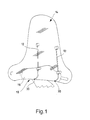
figure 1 shows a perspective view of a pair of fixing devices made according to the invention, applied to the handlebar of a motorcycle for supporting a windshield; -
figure 2 shows an exploded view of some components of a fixing device according to the invention; -
figure 3 shows a cutaway view, in an assembled but non-operative configuration, of the components of the fixing device shown infigure 2 ; -
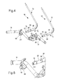
figure 4 shows a perspective view of a pair of fixing devices made according to the invention, which shows the mounting on the handlebar of a motorcycle; -
figure 5 shows a detailed view of a detail offigure 4 ;figure 6 shows a further detailed view of a detail offigure 4 , with the fixing device in assembled and operating configuration; -
figure 7 shows a cutaway view, in an assembled and operative configuration, of the components of each of the fixing devices shown infigure 4 ; and -
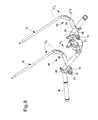
figure 8 shows a perspective view of a pair of fixing devices made according to the invention, which shows the steps of removal thereof from the handlebar of a motorcycle. With reference to the figures, there is shown a device for fixing accessories in a motorcycle according to the present invention, globally indicated withreference numeral 10. In particular, as shown infigure 1 , thefixing device 10 may be suitable for locking one of theshafts 12 for awindshield 14 relative to a fixed component of the motorcycle, such as thehandlebar 16. - At least one tubular element or
sleeve 18 is steadily attached, for example by welding, to thehandlebar 16. In thesleeve 18 the free end of theshaft 12 is insertable, that is, the end whereonwindshield 14 is not attached, through the interposition of at least oneelastic spacer element 20. - More precisely, based on the exemplary embodiment shown in the figures, also the
elastic spacer element 20 is made as a sleeve and at a first end thereof (that facing the free end of the shaft 12), it is refrained by fastening elements from axially sliding, consisting of ascrew 22 with a hexagonal head and a relevantelastic washer 24.Screw 22 is configured to be inserted in a threadedblind hole 26 made axially at the free end ofshaft 12. - The
elastic spacer element 20 is therefore placed in contact, at the end thereof opposite that facing the free end ofshaft 12, with a frusto-conical washer 28 which acts as thrust means. Aspecial nut 30 shaped as a sleeve, provided with an inside threading, engages with a threadedportion 32 ofshaft 12 for moving the frusto-conical washer 28 in abutment against theelastic spacer element 20 and thus form the reversible junction means that allow fixing ofshaft 12 relative tosleeve 18 ofhandlebar 16, as is better specified hereinafter. - According to the invention, at least one
axial locking element 34 is integrally applied onshaft 12, preferably made as a cylindrical bushing provided with at least one flatgrooved portion 36, which engages with a correspondingaxial locking element 38, preferably made as a metal clip spring, attached tosleeve 18 ofhandlebar 16, for example by the insertion in aspecial notch 40 formed on the same sleeve 18 (figure 7 ). In this way, the retain in the axial direction ofshaft 12 in thesleeve 18 is ensured also in the case of loosening ofnut 30 and of theelastic spacer element 20, while the extraction ofsuch shaft 12 from thesame sleeve 18 is only allowed following the rotation, according to a predetermined angle, of thesame shaft 12 around its axis. - More precisely, the
fixing device 10 according to the invention may be operated as follows. In the rest position ofdevice 10, shown for example infigure 3 ,nut 30 is positioned around the threadedportion 32 ofshaft 12 so as to not push the tapered portion of the frusto-conical washer 28 against theelastic spacer element 20, which therefore is at rest. It should be noted that theelastic spacer element 20, as well as the tapered portion of the frusto-conical washer 28 and thecylindrical bushing 34, exhibits a smaller outer circumference than the inside circumference of the tubular element orsleeve 18. In this way, such components are freely insertable in thetubular element 18, as well as freely removable therefrom, in the above rest position ofdevice 10. - In order to mount the
accessory 14, the free end ofshaft 12, with the components associated thereto, in the relieved or rest configuration above, is inserted intosleeve 18, in the axial direction indicated by arrows F1 offigure 4 . Upon insertingshaft 12 intosleeve 18, theclip spring 38 hooks snap-wise onto the flatgrooved portion 36 of thecylindrical bushing 34, immediately ensuring the axial retain of thesame shaft 12. - To steadily lock
device 10, ordevices 10 if a multiple use configuration is required, into position,nut 30 is then rotated in the screwing direction on the relative threadedportion 32 ofshaft 12. Such operation determines a thrust action of the frusto-conical washer 28 on theelastic spacer element 20 which, retained by thecylindrical bushing 34 in turn held into position byscrew 22 and by therelative washer 24, expands locking intosleeve 18, thus makingshaft 12 integral with the motorcycle structure. - In order to remove each
shaft 12, on the other hand, after optionally having removedwindshield 14 or other accessory supported bydevice 10, it will be necessary to first loosen therespective nut 30 for moving theelastic spacer element 20 back into rest position. In such "loosened" configuration ofdevice 10, however, there is still the engagement between theclip spring 38 and the flatgrooved portion 36 of thecylindrical bushing 34, which act as safety system for preventing the accidental extraction ofshaft 12 fromsleeve 18. - It will thus be necessary to rotate each
shaft 12, for example by about 90° outwards with reference tohandlebar 16, as indicated by arrows F3 offigure 8 , so that the cylindrical portion ofbushing 34 widens theclip spring 38, allowing the axial release, that is, the extraction in the axial direction indicated by arrows F2 offigure 8 , ofsuch shaft 12. - It has thus been seen that the device for fixing accessories in a motorcycle, in particular for a windshield, according to the present invention achieves the objects described above. Such fixing device in fact is provided with a safety system which ensures an axial retain also in the case of loosening of the standard junction means of the same device. Moreover, the fixing device does not exhibit visible components, leaving the motorcycle aesthetics unchanged. Finally, the assembly of the fixing device according to the invention still remains simple and quick as it happens for the known fixing devices, that is, not provided with the safety system described above.
- Several changes and variations can be made to the device for fixing accessories in a motorcycle, in particular for a windshield, of the present invention thus conceived, all falling within the same inventive concept; moreover, all details can be replaced with technically equivalent elements. In the practice, the materials used as well as shapes and sizes, can be whatever, according to the technical requirements.
- The scope of protection of the invention therefore is defined by the annexed claims.
Claims (9)
- Device (10) for fixing accessories in a motorcycle, in particular for a windshield (14), comprising at least one shaft (12) that can be inserted in a sleeve element (18) able to be fastened to a fixed component (16) of the motorcycle, a portion of said shaft (12) comprising at least one elastic spacer element (20) that can be inserted in said sleeve element (18) and actuated through reversible joining means (30) between an expanded position, engaged in said sleeve element (18), and a rest position, able to be withdrawn from said sleeve element (18), characterised in that said shaft (12) has at least one axial locking element (34) fixedly applied thereon, which engages with a corresponding axial locking element (38) constrained to said sleeve element (18), so as to ensure that said shaft (12) is held in the axial direction in said sleeve element (18) even in the case where said reversible joining means (30) loosen, and to allow said shaft (12) to be withdrawn from said sleeve element (18) only after the rotation, according to a predetermined angle, of said shaft (12) around its own axis.
- Device (10) according to claim 1, characterised in that said axial locking element (34) of said shaft (12) is made in the form of a cylindrical bushing and in that said axial locking element (38) of said sleeve element (18) is made in the form of a metal spring of clip type.
- Device (10) according to claim 2, characterised in that said metal spring (38) is constrained to said sleeve element (18) through insertion in a notch (40) formed on said sleeve element (18).
- Device (10) according to claim 2 or 3, characterised in that said cylindrical bushing (34) is provided with at least one flat grooved portion (36) into which said metal spring (38) snaps at the moment of insertion of said shaft (12) in said sleeve element (18), immediately ensuring that said shaft (12) is held axially, the cylindrical portion of said cylindrical bushing (34) on the other hand opening out said metal spring (38) after the rotation of said shaft (12) around its own axis, allowing the axial disengagement of said shaft (12).
- Device (10) according to any one of claims 2 to 4, characterised in that said elastic spacer element (20) is made in the form of a sleeve and it is held, at a first end thereof facing towards the free end of said shaft (12), through elements for restraining against axial sliding (22, 24).
- Device (10) according to claim 5, characterised in that said elements for restraining against axial sliding consist of a screw (22) and a relative elastic washer (24), said screw (22) being configured to be inserted in a threaded blind hole (26) made axially at the free end of said shaft (12).
- Device (10) according to claim 5 or 6, characterised in that said elastic spacer element (20) is placed in contact, at its opposite end to the one facing towards the free end of said shaft (12), with a frusto-conical thrust washer (28) that can be actuated by said reversible joining means (30), the tapered portion of said frusto-conical washer (28) being placed against said elastic spacer element (20).
- Device (10) according to claim 7, characterised in that said elastic spacer element (20), said tapered portion of the frusto-conical washer (28) and said cylindrical bushing (34) have an outer circumference smaller than the inner circumference of said sleeve element (18), so as to be freely insertable in said sleeve element (18), as well as freely extractable from it, in said rest position of the device (10).
- Device (10) according to any one of the previous claims, characterised in that said reversible joining means (30) consist of a sleeve-shaped nut, provided with internal threading, which engages with a threaded portion (32) of said shaft (12).
Applications Claiming Priority (1)
| Application Number | Priority Date | Filing Date | Title |
|---|---|---|---|
| ITMI2009A001544A IT1395380B1 (en) | 2009-09-07 | 2009-09-07 | FIXING DEVICE FOR ACCESSORIES IN A MOTORCYCLE, IN PARTICULAR FOR WINDSCREENS |
Publications (2)
| Publication Number | Publication Date |
|---|---|
| EP2292501A1 true EP2292501A1 (en) | 2011-03-09 |
| EP2292501B1 EP2292501B1 (en) | 2014-08-27 |
Family
ID=42101412
Family Applications (1)
| Application Number | Title | Priority Date | Filing Date |
|---|---|---|---|
| EP10168678.0A Active EP2292501B1 (en) | 2009-09-07 | 2010-07-07 | Device for fixing accessories in a motorcycle, in particular for a windshield |
Country Status (7)
| Country | Link |
|---|---|
| US (1) | US8469624B2 (en) |
| EP (1) | EP2292501B1 (en) |
| JP (1) | JP5726453B2 (en) |
| CN (1) | CN102009719B (en) |
| ES (1) | ES2524703T3 (en) |
| IT (1) | IT1395380B1 (en) |
| TW (1) | TWI510400B (en) |
Families Citing this family (4)
| Publication number | Priority date | Publication date | Assignee | Title |
|---|---|---|---|---|
| EP3169578B1 (en) | 2014-07-15 | 2020-12-09 | PIAGGIO & C. S.p.A. | Scooter with windscreen safety assembly |
| JP6295291B2 (en) * | 2015-09-30 | 2018-03-14 | 本田技研工業株式会社 | Screen device and vehicle |
| US11293466B2 (en) * | 2019-09-30 | 2022-04-05 | Gem Products, Inc. | Expanding accessory end adapter |
| DE102020109198A1 (en) * | 2020-04-02 | 2021-10-07 | Bayerische Motoren Werke Aktiengesellschaft | Removable windshield assembly for a tilting vehicle |
Citations (3)
| Publication number | Priority date | Publication date | Assignee | Title |
|---|---|---|---|---|
| GB2263259A (en) * | 1992-01-13 | 1993-07-21 | Piaggio Veicoli Europ | Windscreen connection device in a two-wheel vehicle |
| EP0650885A1 (en) * | 1993-10-27 | 1995-05-03 | PIAGGIO VEICOLI EUROPEI S.p.A. | Quick-fixing device for accessories in a two-wheel vehicle, in particular for windscreens |
| EP1362776A2 (en) * | 2002-05-14 | 2003-11-19 | PIAGGIO & C. S.p.A. | Device for quickly locking a windshield to a two-wheeled vehicle |
Family Cites Families (13)
| Publication number | Priority date | Publication date | Assignee | Title |
|---|---|---|---|---|
| US1566524A (en) * | 1925-12-22 | Separable cuee button | ||
| GB610916A (en) | 1946-04-09 | 1948-10-22 | Anthony Thomas Comiskey | Improvements in motor-cycle wind-shields |
| GB701934A (en) | 1951-05-24 | 1954-01-06 | Watsonian Sidecars Ltd | Improvements relating to windscreens for motor cycles and pedal cycles |
| GB741877A (en) | 1953-01-09 | 1955-12-14 | William Bernard Smith | Improvements relating to weather shields for use on motor cycles, motorised bicyclesand the like |
| US2929600A (en) * | 1955-02-10 | 1960-03-22 | Yankee Metal Products Corp | Rear view mirror supporting bracket |
| US4166650A (en) | 1977-09-01 | 1979-09-04 | Saunders Charles A | Breakaway handlebar-mounted motorcycle fairing |
| US4489973A (en) | 1983-01-17 | 1984-12-25 | Willey Barry A | Mounting systems for motorcycle windshields and fairings |
| JPS59111779U (en) * | 1983-01-20 | 1984-07-27 | 本田技研工業株式会社 | Windshield devices for vehicles such as motorcycles |
| JPH0254794U (en) * | 1988-10-14 | 1990-04-20 | ||
| JPH04104086U (en) * | 1991-02-15 | 1992-09-08 | スズキ株式会社 | Motorcycle windshield device |
| GB9200905D0 (en) | 1992-01-16 | 1992-03-11 | Tempered Spring Company The Li | Method of moulding a non-metallic component onto a metal bar |
| JP3273963B2 (en) * | 1992-03-12 | 2002-04-15 | ヤマハ発動機株式会社 | Motorcycle windscreen device |
| JP4332899B2 (en) * | 2006-10-06 | 2009-09-16 | 株式会社ホンダアクセス | Windshield device for saddle-ride type vehicles |
-
2009
- 2009-09-07 IT ITMI2009A001544A patent/IT1395380B1/en active
-
2010
- 2010-07-07 ES ES10168678.0T patent/ES2524703T3/en active Active
- 2010-07-07 EP EP10168678.0A patent/EP2292501B1/en active Active
- 2010-07-07 US US12/803,792 patent/US8469624B2/en active Active
- 2010-07-22 TW TW099124127A patent/TWI510400B/en active
- 2010-07-29 JP JP2010170612A patent/JP5726453B2/en not_active Expired - Fee Related
- 2010-07-30 CN CN201010243587.0A patent/CN102009719B/en active Active
Patent Citations (3)
| Publication number | Priority date | Publication date | Assignee | Title |
|---|---|---|---|---|
| GB2263259A (en) * | 1992-01-13 | 1993-07-21 | Piaggio Veicoli Europ | Windscreen connection device in a two-wheel vehicle |
| EP0650885A1 (en) * | 1993-10-27 | 1995-05-03 | PIAGGIO VEICOLI EUROPEI S.p.A. | Quick-fixing device for accessories in a two-wheel vehicle, in particular for windscreens |
| EP1362776A2 (en) * | 2002-05-14 | 2003-11-19 | PIAGGIO & C. S.p.A. | Device for quickly locking a windshield to a two-wheeled vehicle |
Also Published As
| Publication number | Publication date |
|---|---|
| JP5726453B2 (en) | 2015-06-03 |
| ES2524703T3 (en) | 2014-12-11 |
| EP2292501B1 (en) | 2014-08-27 |
| IT1395380B1 (en) | 2012-09-14 |
| TWI510400B (en) | 2015-12-01 |
| US8469624B2 (en) | 2013-06-25 |
| US20110058895A1 (en) | 2011-03-10 |
| CN102009719B (en) | 2015-05-27 |
| ITMI20091544A1 (en) | 2011-03-08 |
| TW201109225A (en) | 2011-03-16 |
| CN102009719A (en) | 2011-04-13 |
| JP2011057206A (en) | 2011-03-24 |
Similar Documents
| Publication | Publication Date | Title |
|---|---|---|
| JP5227545B2 (en) | Sprocket wheel cover device for manually operated chainsaw | |
| US8596941B2 (en) | Screw lock accessory retaining device | |
| EP2292501B1 (en) | Device for fixing accessories in a motorcycle, in particular for a windshield | |
| US5919106A (en) | Quick release derailleur | |
| EP2487094A1 (en) | Apparatus for towing a bicycle | |
| US9994248B2 (en) | Steering column device | |
| US9039211B2 (en) | Broad view mirror for a cycle vehicle | |
| US6318924B1 (en) | Quick-connect for mounting objects | |
| US10300974B1 (en) | Balance bike conversion systems | |
| US20170233027A1 (en) | Integrated cycling tool | |
| US20120161503A1 (en) | Axle system for a two-wheeled vehicle | |
| WO2007064645A2 (en) | Detachable bicycle frame | |
| JP2012026565A (en) | Fastening device | |
| US6293883B1 (en) | Quick release derailleur | |
| US20100098484A1 (en) | Quick release device for a pedal | |
| US8234952B2 (en) | Handgrip for handlebar | |
| US20130119633A1 (en) | Mounting system for a wheel of a bicycle | |
| US20170305486A1 (en) | Hand guard | |
| WO2008145497A1 (en) | Wheel axle for cycles and motorcycles provided with anti-removal device | |
| JP2003146284A (en) | Motorcycle clip-on handle | |
| US6267452B1 (en) | Hidden type quick-release wheel hub assembly with reinforcing arrangement | |
| EP3441294A1 (en) | Bicycle component comprising a removable clamping device for fixing to a tubular element of the bicycle | |
| JP3142005U (en) | Tire wheel puller | |
| US10633053B1 (en) | Axle arrangement for a bicycle | |
| US20210362799A1 (en) | Quickly detachable and rotatable bicycle handlebar stem |
Legal Events
| Date | Code | Title | Description |
|---|---|---|---|
| PUAI | Public reference made under article 153(3) epc to a published international application that has entered the european phase |
Free format text: ORIGINAL CODE: 0009012 |
|
| AK | Designated contracting states |
Kind code of ref document: A1 Designated state(s): AL AT BE BG CH CY CZ DE DK EE ES FI FR GB GR HR HU IE IS IT LI LT LU LV MC MK MT NL NO PL PT RO SE SI SK SM TR |
|
| AX | Request for extension of the european patent |
Extension state: BA ME RS |
|
| 17P | Request for examination filed |
Effective date: 20110725 |
|
| GRAP | Despatch of communication of intention to grant a patent |
Free format text: ORIGINAL CODE: EPIDOSNIGR1 |
|
| INTG | Intention to grant announced |
Effective date: 20140620 |
|
| GRAS | Grant fee paid |
Free format text: ORIGINAL CODE: EPIDOSNIGR3 |
|
| GRAA | (expected) grant |
Free format text: ORIGINAL CODE: 0009210 |
|
| AK | Designated contracting states |
Kind code of ref document: B1 Designated state(s): AL AT BE BG CH CY CZ DE DK EE ES FI FR GB GR HR HU IE IS IT LI LT LU LV MC MK MT NL NO PL PT RO SE SI SK SM TR |
|
| REG | Reference to a national code |
Ref country code: GB Ref legal event code: FG4D |
|
| REG | Reference to a national code |
Ref country code: CH Ref legal event code: EP |
|
| REG | Reference to a national code |
Ref country code: AT Ref legal event code: REF Ref document number: 684388 Country of ref document: AT Kind code of ref document: T Effective date: 20140915 |
|
| REG | Reference to a national code |
Ref country code: IE Ref legal event code: FG4D |
|
| REG | Reference to a national code |
Ref country code: DE Ref legal event code: R096 Ref document number: 602010018511 Country of ref document: DE Effective date: 20141009 |
|
| REG | Reference to a national code |
Ref country code: ES Ref legal event code: FG2A Ref document number: 2524703 Country of ref document: ES Kind code of ref document: T3 Effective date: 20141211 |
|
| REG | Reference to a national code |
Ref country code: LT Ref legal event code: MG4D |
|
| REG | Reference to a national code |
Ref country code: NL Ref legal event code: VDEP Effective date: 20140827 |
|
| PG25 | Lapsed in a contracting state [announced via postgrant information from national office to epo] |
Ref country code: PT Free format text: LAPSE BECAUSE OF FAILURE TO SUBMIT A TRANSLATION OF THE DESCRIPTION OR TO PAY THE FEE WITHIN THE PRESCRIBED TIME-LIMIT Effective date: 20141229 Ref country code: BG Free format text: LAPSE BECAUSE OF FAILURE TO SUBMIT A TRANSLATION OF THE DESCRIPTION OR TO PAY THE FEE WITHIN THE PRESCRIBED TIME-LIMIT Effective date: 20141127 Ref country code: LT Free format text: LAPSE BECAUSE OF FAILURE TO SUBMIT A TRANSLATION OF THE DESCRIPTION OR TO PAY THE FEE WITHIN THE PRESCRIBED TIME-LIMIT Effective date: 20140827 Ref country code: SE Free format text: LAPSE BECAUSE OF FAILURE TO SUBMIT A TRANSLATION OF THE DESCRIPTION OR TO PAY THE FEE WITHIN THE PRESCRIBED TIME-LIMIT Effective date: 20140827 Ref country code: GR Free format text: LAPSE BECAUSE OF FAILURE TO SUBMIT A TRANSLATION OF THE DESCRIPTION OR TO PAY THE FEE WITHIN THE PRESCRIBED TIME-LIMIT Effective date: 20141128 Ref country code: FI Free format text: LAPSE BECAUSE OF FAILURE TO SUBMIT A TRANSLATION OF THE DESCRIPTION OR TO PAY THE FEE WITHIN THE PRESCRIBED TIME-LIMIT Effective date: 20140827 Ref country code: NO Free format text: LAPSE BECAUSE OF FAILURE TO SUBMIT A TRANSLATION OF THE DESCRIPTION OR TO PAY THE FEE WITHIN THE PRESCRIBED TIME-LIMIT Effective date: 20141127 |
|
| PG25 | Lapsed in a contracting state [announced via postgrant information from national office to epo] |
Ref country code: IS Free format text: LAPSE BECAUSE OF FAILURE TO SUBMIT A TRANSLATION OF THE DESCRIPTION OR TO PAY THE FEE WITHIN THE PRESCRIBED TIME-LIMIT Effective date: 20141227 Ref country code: HR Free format text: LAPSE BECAUSE OF FAILURE TO SUBMIT A TRANSLATION OF THE DESCRIPTION OR TO PAY THE FEE WITHIN THE PRESCRIBED TIME-LIMIT Effective date: 20140827 Ref country code: CY Free format text: LAPSE BECAUSE OF FAILURE TO SUBMIT A TRANSLATION OF THE DESCRIPTION OR TO PAY THE FEE WITHIN THE PRESCRIBED TIME-LIMIT Effective date: 20140827 Ref country code: LV Free format text: LAPSE BECAUSE OF FAILURE TO SUBMIT A TRANSLATION OF THE DESCRIPTION OR TO PAY THE FEE WITHIN THE PRESCRIBED TIME-LIMIT Effective date: 20140827 |
|
| PG25 | Lapsed in a contracting state [announced via postgrant information from national office to epo] |
Ref country code: NL Free format text: LAPSE BECAUSE OF FAILURE TO SUBMIT A TRANSLATION OF THE DESCRIPTION OR TO PAY THE FEE WITHIN THE PRESCRIBED TIME-LIMIT Effective date: 20140827 |
|
| PG25 | Lapsed in a contracting state [announced via postgrant information from national office to epo] |
Ref country code: EE Free format text: LAPSE BECAUSE OF FAILURE TO SUBMIT A TRANSLATION OF THE DESCRIPTION OR TO PAY THE FEE WITHIN THE PRESCRIBED TIME-LIMIT Effective date: 20140827 Ref country code: DK Free format text: LAPSE BECAUSE OF FAILURE TO SUBMIT A TRANSLATION OF THE DESCRIPTION OR TO PAY THE FEE WITHIN THE PRESCRIBED TIME-LIMIT Effective date: 20140827 Ref country code: SK Free format text: LAPSE BECAUSE OF FAILURE TO SUBMIT A TRANSLATION OF THE DESCRIPTION OR TO PAY THE FEE WITHIN THE PRESCRIBED TIME-LIMIT Effective date: 20140827 Ref country code: CZ Free format text: LAPSE BECAUSE OF FAILURE TO SUBMIT A TRANSLATION OF THE DESCRIPTION OR TO PAY THE FEE WITHIN THE PRESCRIBED TIME-LIMIT Effective date: 20140827 Ref country code: RO Free format text: LAPSE BECAUSE OF FAILURE TO SUBMIT A TRANSLATION OF THE DESCRIPTION OR TO PAY THE FEE WITHIN THE PRESCRIBED TIME-LIMIT Effective date: 20140827 |
|
| REG | Reference to a national code |
Ref country code: DE Ref legal event code: R097 Ref document number: 602010018511 Country of ref document: DE |
|
| PG25 | Lapsed in a contracting state [announced via postgrant information from national office to epo] |
Ref country code: PL Free format text: LAPSE BECAUSE OF FAILURE TO SUBMIT A TRANSLATION OF THE DESCRIPTION OR TO PAY THE FEE WITHIN THE PRESCRIBED TIME-LIMIT Effective date: 20140827 |
|
| PLBE | No opposition filed within time limit |
Free format text: ORIGINAL CODE: 0009261 |
|
| STAA | Information on the status of an ep patent application or granted ep patent |
Free format text: STATUS: NO OPPOSITION FILED WITHIN TIME LIMIT |
|
| 26N | No opposition filed |
Effective date: 20150528 |
|
| PG25 | Lapsed in a contracting state [announced via postgrant information from national office to epo] |
Ref country code: SI Free format text: LAPSE BECAUSE OF FAILURE TO SUBMIT A TRANSLATION OF THE DESCRIPTION OR TO PAY THE FEE WITHIN THE PRESCRIBED TIME-LIMIT Effective date: 20140827 |
|
| PG25 | Lapsed in a contracting state [announced via postgrant information from national office to epo] |
Ref country code: MC Free format text: LAPSE BECAUSE OF FAILURE TO SUBMIT A TRANSLATION OF THE DESCRIPTION OR TO PAY THE FEE WITHIN THE PRESCRIBED TIME-LIMIT Effective date: 20140827 |
|
| REG | Reference to a national code |
Ref country code: CH Ref legal event code: PL |
|
| PG25 | Lapsed in a contracting state [announced via postgrant information from national office to epo] |
Ref country code: LU Free format text: LAPSE BECAUSE OF FAILURE TO SUBMIT A TRANSLATION OF THE DESCRIPTION OR TO PAY THE FEE WITHIN THE PRESCRIBED TIME-LIMIT Effective date: 20150707 |
|
| REG | Reference to a national code |
Ref country code: IE Ref legal event code: MM4A |
|
| PG25 | Lapsed in a contracting state [announced via postgrant information from national office to epo] |
Ref country code: LI Free format text: LAPSE BECAUSE OF NON-PAYMENT OF DUE FEES Effective date: 20150731 Ref country code: CH Free format text: LAPSE BECAUSE OF NON-PAYMENT OF DUE FEES Effective date: 20150731 |
|
| REG | Reference to a national code |
Ref country code: FR Ref legal event code: PLFP Year of fee payment: 7 |
|
| PG25 | Lapsed in a contracting state [announced via postgrant information from national office to epo] |
Ref country code: BE Free format text: LAPSE BECAUSE OF FAILURE TO SUBMIT A TRANSLATION OF THE DESCRIPTION OR TO PAY THE FEE WITHIN THE PRESCRIBED TIME-LIMIT Effective date: 20140827 Ref country code: IE Free format text: LAPSE BECAUSE OF NON-PAYMENT OF DUE FEES Effective date: 20150707 |
|
| PG25 | Lapsed in a contracting state [announced via postgrant information from national office to epo] |
Ref country code: MT Free format text: LAPSE BECAUSE OF FAILURE TO SUBMIT A TRANSLATION OF THE DESCRIPTION OR TO PAY THE FEE WITHIN THE PRESCRIBED TIME-LIMIT Effective date: 20140827 |
|
| PG25 | Lapsed in a contracting state [announced via postgrant information from national office to epo] |
Ref country code: SM Free format text: LAPSE BECAUSE OF FAILURE TO SUBMIT A TRANSLATION OF THE DESCRIPTION OR TO PAY THE FEE WITHIN THE PRESCRIBED TIME-LIMIT Effective date: 20140827 Ref country code: HU Free format text: LAPSE BECAUSE OF FAILURE TO SUBMIT A TRANSLATION OF THE DESCRIPTION OR TO PAY THE FEE WITHIN THE PRESCRIBED TIME-LIMIT; INVALID AB INITIO Effective date: 20100707 |
|
| REG | Reference to a national code |
Ref country code: FR Ref legal event code: PLFP Year of fee payment: 8 |
|
| PG25 | Lapsed in a contracting state [announced via postgrant information from national office to epo] |
Ref country code: TR Free format text: LAPSE BECAUSE OF FAILURE TO SUBMIT A TRANSLATION OF THE DESCRIPTION OR TO PAY THE FEE WITHIN THE PRESCRIBED TIME-LIMIT Effective date: 20140827 |
|
| PG25 | Lapsed in a contracting state [announced via postgrant information from national office to epo] |
Ref country code: MK Free format text: LAPSE BECAUSE OF FAILURE TO SUBMIT A TRANSLATION OF THE DESCRIPTION OR TO PAY THE FEE WITHIN THE PRESCRIBED TIME-LIMIT Effective date: 20140827 |
|
| REG | Reference to a national code |
Ref country code: FR Ref legal event code: PLFP Year of fee payment: 9 |
|
| PG25 | Lapsed in a contracting state [announced via postgrant information from national office to epo] |
Ref country code: AL Free format text: LAPSE BECAUSE OF FAILURE TO SUBMIT A TRANSLATION OF THE DESCRIPTION OR TO PAY THE FEE WITHIN THE PRESCRIBED TIME-LIMIT Effective date: 20140827 |
|
| P01 | Opt-out of the competence of the unified patent court (upc) registered |
Effective date: 20230526 |
|
| PGFP | Annual fee paid to national office [announced via postgrant information from national office to epo] |
Ref country code: IT Payment date: 20240507 Year of fee payment: 15 Ref country code: FR Payment date: 20240628 Year of fee payment: 15 |
|
| PGFP | Annual fee paid to national office [announced via postgrant information from national office to epo] |
Ref country code: DE Payment date: 20240719 Year of fee payment: 15 |
|
| PGFP | Annual fee paid to national office [announced via postgrant information from national office to epo] |
Ref country code: GB Payment date: 20240723 Year of fee payment: 15 |
|
| PGFP | Annual fee paid to national office [announced via postgrant information from national office to epo] |
Ref country code: ES Payment date: 20240801 Year of fee payment: 15 |
|
| PGFP | Annual fee paid to national office [announced via postgrant information from national office to epo] |
Ref country code: AT Payment date: 20240718 Year of fee payment: 15 |
|
| REG | Reference to a national code |
Ref country code: DE Ref legal event code: R119 Ref document number: 602010018511 Country of ref document: DE |
|
| REG | Reference to a national code |
Ref country code: AT Ref legal event code: MM01 Ref document number: 684388 Country of ref document: AT Kind code of ref document: T Effective date: 20250707 |
|
| GBPC | Gb: european patent ceased through non-payment of renewal fee |
Effective date: 20250707 |
|
| PG25 | Lapsed in a contracting state [announced via postgrant information from national office to epo] |
Ref country code: GB Free format text: LAPSE BECAUSE OF NON-PAYMENT OF DUE FEES Effective date: 20250707 |
|
| PG25 | Lapsed in a contracting state [announced via postgrant information from national office to epo] |
Ref country code: DE Free format text: LAPSE BECAUSE OF NON-PAYMENT OF DUE FEES Effective date: 20260203 |
|
| PG25 | Lapsed in a contracting state [announced via postgrant information from national office to epo] |
Ref country code: AT Free format text: LAPSE BECAUSE OF NON-PAYMENT OF DUE FEES Effective date: 20250707 |
|
| PG25 | Lapsed in a contracting state [announced via postgrant information from national office to epo] |
Ref country code: FR Free format text: LAPSE BECAUSE OF NON-PAYMENT OF DUE FEES Effective date: 20250731 |