EP3441294A1 - Bicycle component comprising a removable clamping device for fixing to a tubular element of the bicycle - Google Patents
Bicycle component comprising a removable clamping device for fixing to a tubular element of the bicycle Download PDFInfo
- Publication number
- EP3441294A1 EP3441294A1 EP18186307.7A EP18186307A EP3441294A1 EP 3441294 A1 EP3441294 A1 EP 3441294A1 EP 18186307 A EP18186307 A EP 18186307A EP 3441294 A1 EP3441294 A1 EP 3441294A1
- Authority
- EP
- European Patent Office
- Prior art keywords
- clamping
- segment
- clamping segment
- bicycle
- segments
- Prior art date
- Legal status (The legal status is an assumption and is not a legal conclusion. Google has not performed a legal analysis and makes no representation as to the accuracy of the status listed.)
- Withdrawn
Links
Images


Classifications
-
- B—PERFORMING OPERATIONS; TRANSPORTING
- B62—LAND VEHICLES FOR TRAVELLING OTHERWISE THAN ON RAILS
- B62K—CYCLES; CYCLE FRAMES; CYCLE STEERING DEVICES; RIDER-OPERATED TERMINAL CONTROLS SPECIALLY ADAPTED FOR CYCLES; CYCLE AXLE SUSPENSIONS; CYCLE SIDECARS, FORECARS, OR THE LIKE
- B62K23/00—Rider-operated controls specially adapted for cycles, i.e. means for initiating control operations, e.g. levers, grips
- B62K23/02—Rider-operated controls specially adapted for cycles, i.e. means for initiating control operations, e.g. levers, grips hand actuated
-
- B—PERFORMING OPERATIONS; TRANSPORTING
- B62—LAND VEHICLES FOR TRAVELLING OTHERWISE THAN ON RAILS
- B62K—CYCLES; CYCLE FRAMES; CYCLE STEERING DEVICES; RIDER-OPERATED TERMINAL CONTROLS SPECIALLY ADAPTED FOR CYCLES; CYCLE AXLE SUSPENSIONS; CYCLE SIDECARS, FORECARS, OR THE LIKE
- B62K19/00—Cycle frames
- B62K19/30—Frame parts shaped to receive other cycle parts or accessories
- B62K19/36—Frame parts shaped to receive other cycle parts or accessories for attaching saddle pillars, e.g. adjustable during ride
-
- B—PERFORMING OPERATIONS; TRANSPORTING
- B62—LAND VEHICLES FOR TRAVELLING OTHERWISE THAN ON RAILS
- B62M—RIDER PROPULSION OF WHEELED VEHICLES OR SLEDGES; POWERED PROPULSION OF SLEDGES OR SINGLE-TRACK CYCLES; TRANSMISSIONS SPECIALLY ADAPTED FOR SUCH VEHICLES
- B62M25/00—Actuators for gearing speed-change mechanisms specially adapted for cycles
- B62M25/02—Actuators for gearing speed-change mechanisms specially adapted for cycles with mechanical transmitting systems, e.g. cables, levers
- B62M25/04—Actuators for gearing speed-change mechanisms specially adapted for cycles with mechanical transmitting systems, e.g. cables, levers hand actuated
-
- F—MECHANICAL ENGINEERING; LIGHTING; HEATING; WEAPONS; BLASTING
- F16—ENGINEERING ELEMENTS AND UNITS; GENERAL MEASURES FOR PRODUCING AND MAINTAINING EFFECTIVE FUNCTIONING OF MACHINES OR INSTALLATIONS; THERMAL INSULATION IN GENERAL
- F16M—FRAMES, CASINGS OR BEDS OF ENGINES, MACHINES OR APPARATUS, NOT SPECIFIC TO ENGINES, MACHINES OR APPARATUS PROVIDED FOR ELSEWHERE; STANDS; SUPPORTS
- F16M11/00—Stands or trestles as supports for apparatus or articles placed thereon ; Stands for scientific apparatus such as gravitational force meters
- F16M11/02—Heads
- F16M11/04—Means for attachment of apparatus; Means allowing adjustment of the apparatus relatively to the stand
- F16M11/041—Allowing quick release of the apparatus
-
- F—MECHANICAL ENGINEERING; LIGHTING; HEATING; WEAPONS; BLASTING
- F16—ENGINEERING ELEMENTS AND UNITS; GENERAL MEASURES FOR PRODUCING AND MAINTAINING EFFECTIVE FUNCTIONING OF MACHINES OR INSTALLATIONS; THERMAL INSULATION IN GENERAL
- F16M—FRAMES, CASINGS OR BEDS OF ENGINES, MACHINES OR APPARATUS, NOT SPECIFIC TO ENGINES, MACHINES OR APPARATUS PROVIDED FOR ELSEWHERE; STANDS; SUPPORTS
- F16M13/00—Other supports for positioning apparatus or articles; Means for steadying hand-held apparatus or articles
- F16M13/02—Other supports for positioning apparatus or articles; Means for steadying hand-held apparatus or articles for supporting on, or attaching to, an object, e.g. tree, gate, window-frame, cycle
-
- B—PERFORMING OPERATIONS; TRANSPORTING
- B62—LAND VEHICLES FOR TRAVELLING OTHERWISE THAN ON RAILS
- B62J—CYCLE SADDLES OR SEATS; AUXILIARY DEVICES OR ACCESSORIES SPECIALLY ADAPTED TO CYCLES AND NOT OTHERWISE PROVIDED FOR, e.g. ARTICLE CARRIERS OR CYCLE PROTECTORS
- B62J6/00—Arrangement of optical signalling or lighting devices on cycles; Mounting or supporting thereof; Circuits therefor
- B62J6/16—Arrangement of switches
-
- B—PERFORMING OPERATIONS; TRANSPORTING
- B62—LAND VEHICLES FOR TRAVELLING OTHERWISE THAN ON RAILS
- B62K—CYCLES; CYCLE FRAMES; CYCLE STEERING DEVICES; RIDER-OPERATED TERMINAL CONTROLS SPECIALLY ADAPTED FOR CYCLES; CYCLE AXLE SUSPENSIONS; CYCLE SIDECARS, FORECARS, OR THE LIKE
- B62K23/00—Rider-operated controls specially adapted for cycles, i.e. means for initiating control operations, e.g. levers, grips
- B62K23/02—Rider-operated controls specially adapted for cycles, i.e. means for initiating control operations, e.g. levers, grips hand actuated
- B62K23/06—Levers
-
- B—PERFORMING OPERATIONS; TRANSPORTING
- B62—LAND VEHICLES FOR TRAVELLING OTHERWISE THAN ON RAILS
- B62M—RIDER PROPULSION OF WHEELED VEHICLES OR SLEDGES; POWERED PROPULSION OF SLEDGES OR SINGLE-TRACK CYCLES; TRANSMISSIONS SPECIALLY ADAPTED FOR SUCH VEHICLES
- B62M9/00—Transmissions characterised by use of an endless chain, belt, or the like
- B62M9/04—Transmissions characterised by use of an endless chain, belt, or the like of changeable ratio
- B62M9/06—Transmissions characterised by use of an endless chain, belt, or the like of changeable ratio using a single chain, belt, or the like
- B62M9/10—Transmissions characterised by use of an endless chain, belt, or the like of changeable ratio using a single chain, belt, or the like involving different-sized wheels, e.g. rear sprocket chain wheels selectively engaged by the chain, belt, or the like
- B62M9/12—Transmissions characterised by use of an endless chain, belt, or the like of changeable ratio using a single chain, belt, or the like involving different-sized wheels, e.g. rear sprocket chain wheels selectively engaged by the chain, belt, or the like the chain, belt, or the like being laterally shiftable, e.g. using a rear derailleur
- B62M9/131—Front derailleurs
- B62M9/135—Mounting the derailleur on the frame
-
- F—MECHANICAL ENGINEERING; LIGHTING; HEATING; WEAPONS; BLASTING
- F16—ENGINEERING ELEMENTS AND UNITS; GENERAL MEASURES FOR PRODUCING AND MAINTAINING EFFECTIVE FUNCTIONING OF MACHINES OR INSTALLATIONS; THERMAL INSULATION IN GENERAL
- F16B—DEVICES FOR FASTENING OR SECURING CONSTRUCTIONAL ELEMENTS OR MACHINE PARTS TOGETHER, e.g. NAILS, BOLTS, CIRCLIPS, CLAMPS, CLIPS OR WEDGES; JOINTS OR JOINTING
- F16B2/00—Friction-grip releasable fastenings
- F16B2/02—Clamps, i.e. with gripping action effected by positive means other than the inherent resistance to deformation of the material of the fastening
- F16B2/06—Clamps, i.e. with gripping action effected by positive means other than the inherent resistance to deformation of the material of the fastening external, i.e. with contracting action
-
- F—MECHANICAL ENGINEERING; LIGHTING; HEATING; WEAPONS; BLASTING
- F16—ENGINEERING ELEMENTS AND UNITS; GENERAL MEASURES FOR PRODUCING AND MAINTAINING EFFECTIVE FUNCTIONING OF MACHINES OR INSTALLATIONS; THERMAL INSULATION IN GENERAL
- F16B—DEVICES FOR FASTENING OR SECURING CONSTRUCTIONAL ELEMENTS OR MACHINE PARTS TOGETHER, e.g. NAILS, BOLTS, CIRCLIPS, CLAMPS, CLIPS OR WEDGES; JOINTS OR JOINTING
- F16B7/00—Connections of rods or tubes, e.g. of non-circular section, mutually, including resilient connections
- F16B7/04—Clamping or clipping connections
Definitions
- the present invention relates to a bicycle component comprising a removable clamping device for fixing to a tubular element of the bicycle.
- the bicycle component comprises a main body having a rear surface configured to be associated with the tubular element.
- the invention has a preferred application in the field of racing bicycles.
- a bicycle component such as a control assembly of bicycle handlebars, to be associated with a tubular element such as a handlebar tube, and a derailleur, to be associated with a tubular element such as a tube of the frame, in particular with the seat tube of the frame (i.e. that which supports the saddle tube of the bicycle at the top).
- a removable clamping device which typically comprises an annular strap element, fixed to the main body of the bicycle component and wrapping around the tubular element of the bicycle.
- the strap typically metallic, is clamped through the screwing of a nut on a screw, so as to securely tighten together two substantially facing end portions of the strap.
- the mounting operations of the aforementioned bicycle component include the positioning of the screw and the screwing of the nut, and take a certain amount of time.
- US 2015/0096402 and US 2015/0000452 show removable clamping devices that comprise an annular element able to be clamped through a screw.
- the technical problem at the basis of the present invention is that of providing a bicycle component comprising a removable clamping device for fixing to a tubular element of the bicycle, which ensures quick mounting and dismounting of the bicycle component from the tubular element of the bicycle, at the same time ensuring secure and reliable clamping.
- the present invention therefore relates to a bicycle component comprising a main body and a removable clamping device for fixing to a tubular element of the bicycle, wherein the removable clamping device comprises a plurality of clamping segments configured to be arranged around the entire circumference of the tubular element of the bicycle and to be removably clamped onto it, characterized in that there are at least three clamping segments, connected together in succession in pairs by at least three connection systems, wherein the connection systems comprise at least one hinge and at least one removable fastener.
- the aforementioned removable clamping device makes it possible to obtain quick mounting and dismounting of the bicycle component from the tubular element of the bicycle, through the clamping of the at least three clamping segments through the at least one removable fastener.
- the clamping is provided by the fastening of the at least one removable fastener between two clamping segments in succession. Such clamping has proven secure and reliable.
- connection systems define hinging axes, parallel to one another along a direction according to which the tubular element is intended to be arranged when the bicycle component is fixed thereto, the hinging axes comprising a stable hinging axis for every hinge and a virtual hinging axis for every removable fastener.
- virtual hinging it is meant that there is a hinging axis only when the fastening is closed, whereas the hinging axis disappears when the fastening is open, with its parts separated from one another.
- the clamping device is capable of taking up at least three configurations:
- the surface abutment at the tubular element increases the friction and stably locks the bicycle component on the tubular element.
- one of the clamping segments is arranged at least partially juxtaposed over an adjacent clamping segment.
- such a juxtaposed clamping segment has the effect of tightening the remaining clamping segments around the tubular element.
- the clamping segment arranged at least partially juxtaposed is rested on the adjacent clamping segment.
- the clamping segment arranged at least partially juxtaposed is at least partially recessed in a seat formed in the adjacent clamping segment.
- the external space occupied by the clamping device is extremely small.
- the clamping segment arranged at least partially juxtaposed comprises an actuating end portion.
- At least one of the clamping segments is fixed to the main body of the bicycle component.
- At least one of the clamping segments has adjustable length.
- the at least one of the clamping segments with adjustable length comprises a screw/nut screw coupling between two parts thereof.
- one of the clamping segments has a fastening end portion comprising a plurality of hooks.
- the at least three hinges comprise a fourth hinge, between the third and the fourth clamping segment.
- the bicycle component according to the invention comprises:
- the at least three hinges comprise a fourth hinge, between the third clamping segment and the perforated bush.
- the component is a control assembly of bicycle handlebars or the component is a derailleur.
- reference numerals 10, 210 and 410 indicate three preferred embodiments of a control assembly of handlebars in accordance with the present invention
- reference numerals 110, 310 and 510 indicate three preferred embodiments of a derailleur in accordance with the present invention.
- the control assembly of handlebars 10, 210, 410 and the bicycle derailleur 110, 310, 510 will also be indicated with the general term "bicycle component" in accordance with the present invention.
- the type of the specific bicycle component is not relevant for the purposes of the invention and therefore the features described hereinafter with specific reference to each of the aforementioned embodiments can be adopted for a control of handlebars, for a derailleur, and for other component.
- the bicycle component is intended to be fixed to a tubular element of the bicycle.
- the tubular element is a tube of the bicycle handlebars.
- the tubular element is a seat tube of the frame (i.e. that which supports the saddle tube of the bicycle at the top).
- reference numeral 10 indicates a first preferred embodiment of a control assembly of bicycle handlebars in accordance with the present invention.
- the bicycle component 10 comprises a removable clamping device 20 for fixing to the tubular element (not illustrated) of the bicycle.
- a main body 12 of the bicycle component 10 has a rear surface 14 configured to be associated with the tubular element and an opposite front surface 16.
- the removable clamping device 20 comprises a plurality of clamping segments configured to be arranged around the entire circumference of the tubular element of the bicycle and to be removably clamped on it.
- connection systems comprise hinges and a removable fastener 40.
- connection systems define hinging axes, parallel to one another along a direction according to which the tubular element is intended to be arranged when the bicycle component 10 is fixed thereto; the hinging axes comprise a stable hinging axis for every hinge and a virtual hinging axis for the removable fastener 40.
- clamping segments there are four clamping segments, indicated with 30, 32, 34 and 36, and there are three hinges, indicated with 31, 33 and 35.
- the clamping segment 30 is fixed to the main body 12 of the bicycle component, through a pin 30a that is preferably externally threaded, or through a screw screwed into an axial cavity of such a pin, without external threading.
- the clamping segment 30 can be fixed to the main body 12 through overmolding.
- the clamping segment 30 is substantially V-shaped, with a first end portion, at which the hinge 31 is provided, and a second opposite end portion where a hook 40a is provided that forms part of the removable fastener 40.
- the clamping segment 32 extends for an arc between a first end portion and a second end portion opposite the first, provided at the opposite end portions with the hinges 31 and 33, respectively.
- the clamping segment 34 extends between a first end portion and a second end portion opposite the first, and is connected to the clamping segment 32 through the hinge 33, arranged at the second end portion of the clamping segment 32 and at the first end portion of the clamping segment 34.
- the clamping segment 36 extends for an arc between a first end portion and a second end portion opposite the first, and is connected to the clamping segment 34 through the hinge 35, arranged at the second end portion of the clamping segment 34 and at an intermediate area of the clamping segment 36.
- the clamping segment 36 is provided at the second end portion with a counter-hook 40b, which forms part of the removable fastener 40.
- the clamping device 20 is capable of taking up at least three configurations.
- a first configuration is a clamped configuration ( figures 3 , 5 and 7 ), wherein the removable fastener 40 is closed and the clamping segments 30, 32, 34 and 36 are arranged in succession substantially defining a minimum closed line ( fig. 7 ), the hinging axes are all arranged close to such a minimum closed line, and the clamping device 20 is clamped when applied to the tubular element;
- a second configuration is an open configuration ( figures 2 , 4 and 6 ), wherein the removable fastener 40 is open and the clamping segments 30, 32, 34 and 36 are arranged at least partially far from the minimum closed line, at least one of the hinging axes is far from the minimum closed line, and the clamping device 20 can be positioned around the tubular element;
- a third configuration is an intermediate configuration (not illustrated in the figures but obvious from what has been described), wherein the removable fastener 40 is closed and the clamping segments 30, 32, 34 and 36 are arranged at least partially far from the minimum closed line, at least one of the hinging axes is far from the minimum closed line, and the clamping device 20 is not clamped when applied to the tubular element.
- the clamping segment 34 is arranged at least partially juxtaposed over the clamping segment 32.
- the clamping segment 34 arranged at least partially juxtaposed is at least partially recessed in a seat 32a formed in the clamping segment 32.
- the clamping segment 36 comprises an actuating end portion 36a.
- both the mounting and the dismounting are simple and quick.
- FIG. 8-14 A first preferred embodiment of a bicycle derailleur 110 in accordance with the invention is illustrated in figures 8-14 , in which elements structurally or functionally equivalent to those already described with reference to the first embodiment of the control assembly of bicycle handlebars 10 of the invention are indicated with the same reference numeral.
- the derailleur 110 is fixed to a tubular element 150 of the bicycle, in particular to the seat tube of the frame.
- the bicycle component 110 comprises a removable clamping device 120 for fixing to the tubular element 150.
- the removable clamping device 120 comprises a plurality of clamping segments configured to be arranged around the entire circumference of the tubular element 150 and to be removably clamped on it.
- connection systems comprise hinges and a removable fastener 40.
- connection systems define hinging axes, parallel to one another along the direction Y according to which the tubular element 150 is arranged when the bicycle component 110 is fixed thereto; these axes comprise a stable hinging axis for every hinge and a virtual hinging axis for the removable fastener 40.
- the clamping segment 130 is fixed to the main body 12 of the bicycle component, at an appendage portion 130b thereof, equipped with a hole 130c.
- the hole 130c is passed through by a fixing screw to the main body 12.
- the clamping segment 130 extends for an arc between a first end portion and a second end portion opposite the first, a hook 40a that forms part of the removable fastener 40 being provided at the first end portion.
- the clamping segment 132 extends between a first end portion and a second end portion opposite the first, connected to the clamping segment 130 through a hinge 131, arranged at the second end portion of the clamping segment 130 and at the first end portion of the clamping segment 132.
- the clamping segment 134 extends for an arc between a first end portion and a second end portion opposite the first, and is connected to the clamping segment 132 through the hinge 133, arranged at the second end portion of the clamping segment 132 and at an intermediate area of the clamping segment 134.
- the clamping segment 134 is provided at the second end portion with a counter-hook 40b, which forms part of the removable fastener 40.
- the clamping device 120 is capable of taking up at least three configurations:
- the clamping segment 132 is arranged at least partially juxtaposed over the clamping segment 130.
- the clamping segment 132 arranged at least partially juxtaposed is at least partially recessed in a seat 130a formed in the clamping segment 130.
- the clamping segment 134 comprises an actuating end portion 134a.
- the ways of using the clamping device 120 of the component 110 are clear from what has been described.
- the fastener 40 is closed (by fastening the hook 40a to the counter-hook 40b), reaching the intermediate configuration; finally, by acting on the clamping segment 134 in the direction to take it above and against the clamping segment 132 and this above and against the clamping segment 130, the clamping condition is reached.
- the component 110 is locked on the tubular element of the bicycle in a secure and stable manner.
- both the mounting and the dismounting are simple and quick.
- FIG. 15-22 A second preferred embodiment of the control assembly of bicycle handlebars 210 in accordance with the invention is illustrated in figures 15-22 , in which elements structurally or functionally equivalent to those already described with reference to the prima embodiment of the control assembly of bicycle handlebars 10 of the invention of figures 1-7 are indicated with the same reference numeral.
- the bicycle component 210 comprises a removable clamping device 220 for fixing to the tubular element (not illustrated) of the bicycle.
- a main body 12 of the bicycle component 210 has a rear surface 14 configured to be associated with the tubular element and an opposite front surface 16.
- the removable clamping device 220 comprises a plurality of clamping segments configured to be arranged around the entire circumference of the tubular element of the bicycle and to be removably clamped on it.
- connection systems comprise hinges and a removable fastener 40.
- connection systems define hinging axes, parallel to one another along a direction according to which the tubular element is intended to be arranged when the bicycle component 210 is fixed thereto; the hinging axes comprise a stable hinging axis for every hinge and a virtual hinging axis for the removable fastener 40.
- clamping segments there are five clamping segments, indicated with 230, 232, 234, 236 and 238, and there are four hinges, indicated with 231, 233, 235 and 237.
- the clamping segment 230 is fixed to the main body 12 of the bicycle component, through a pin 30a that is preferably externally threaded, or through a screw screwed into an axial cavity of such a pin, without external threading.
- the clamping segment 30 can be fixed to the main body 12 through overmolding.
- the clamping segment 230 is substantially V-shaped, with a first end portion, at which the hinge 231 is provided, and a second opposite end portion where a hook 40a that forms part of the removable fastener 40 is provided.
- the clamping segment 232 extends for an arc between a first end portion and a second end portion opposite the first, provided at the opposite end portions with the hinges 231 and 233, respectively.
- the clamping segment 234 extends between a first end portion and a second end portion opposite the first, and is connected to the clamping segment 232 through the hinge 233, arranged at the second end portion of the clamping segment 232 and at the first end portion of the clamping segment 234.
- the clamping segment 236 extends for an arc between a first end portion and a second end portion opposite the first, and is connected to the clamping segment 234 through a hinge 235, arranged at an intermediate area of the clamping segment 234 and at the first end portion of the clamping segment 236.
- the clamping segment 238 extends between a first end portion and a second end portion opposite the first, and is connected to the clamping segment 236 through a hinge 237, arranged at the second end portion of the clamping segment 236 and at the first end portion of the clamping segment 238.
- the clamping segment 238 is provided at the second end portion with a counter-hook 40b that forms part of the removable fastener 40.
- the clamping device 220 is capable of taking up at least three configurations.
- a first configuration is a clamped configuration ( figures 15, 17 , 18, 20 and 21 ), wherein the removable fastener 40 is closed and the clamping segments 230, 232, 234, 236 and 238 are arranged in succession substantially defining a minimum closed line, the hinging axes are all arranged close to such a minimum closed line, and the clamping device 220 is clamped when applied to the tubular element;
- a second configuration is an open configuration ( figures 16 , 19 and 22 ), wherein the removable fastener 40 is open and the clamping segments 230, 232, 234, 236 and 238 are arranged at least partially far from the minimum closed line, at least one of the hinging axes is far from the minimum closed line, and the clamping device 220 can be positioned around the tubular element.
- a third configuration is an intermediate configuration (not illustrated in the figures but obvious from what has been described), wherein the removable fastener 40 is closed and the clamping segments 230, 232, 234, 236 and 238 are arranged at least partially far from the minimum closed line, at least one of the hinging axes is far from the minimum closed line, and the clamping device 220 is not clamped when applied to the tubular element.
- the clamping segment 234 is arranged at least partially juxtaposed over the clamping segment 232. In particular, the clamping segment 234 rests on the clamping segment 232.
- the clamping segment 234 comprises an actuating end portion 234a.
- the clamping segment 236 has adjustable length.
- the clamping segment 236 comprises a screw/nut screw coupling between two parts thereof.
- a perforated bush 260 is fixed to the clamping segment 234 at its intermediate area.
- a threaded head of the first end of the clamping segment 236 is inserted through the perforated bush 260.
- a threaded nut in screwing engagement is adjustable on the threaded head so as to keep it engaged with the perforated bush 260.
- the hinge 235 is arranged between the clamping segment 234 and the perforated bush 260.
- the ways of using the clamping device 220 of the component 210 are clear from what has been described.
- the clamping device 220 In order to fix the component 210 to the tubular element of the bicycle, it is necessary to take the clamping device 220 into its open configuration and to arrange it around the tubular element so as to embrace it; at this point, it is possible to adjust the width of the clamping device 220, unscrewing or screwing in the threaded head of the clamping segment 236 in the bush 260; thereafter, the fastener 40 is closed (by fastening the hook 40a to the counter-hook 40b), reaching the intermediate configuration; finally, by acting on the end 234a of the clamping segment 234 in the direction to take the latter above and against the clamping segment 232, carrying the clamping segment 236 above it, the clamping condition is reached.
- the component 210 is locked on the tubular element of the bicycle in a secure and stable manner.
- both the mounting and the dismounting are simple and quick.
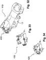
- FIG. 23-28 A second preferred embodiment of a bicycle derailleur 310 in accordance with the invention is illustrated in figures 23-28 , in which elements structurally or functionally equivalent to those already described with reference to the first embodiment of the bicycle derailleur 110 of the invention of figures 8-14 are indicated with the same reference numeral.
- the derailleur 310 is fixed to a tubular element 150 of the bicycle, in particular to the seat tube of the frame.
- the bicycle component 310 comprises a removable clamping device 320 for fixing to the tubular element 150.
- the removable clamping device 320 comprises a plurality of clamping segments configured to be arranged around the entire circumference of the tubular element 150 and to be removably clamped on it.
- connection systems comprise hinges and a removable fastener 40.
- connection systems define hinging axes, parallel to one another along the direction Y according to which the tubular element 150 is arranged when the bicycle component 310 is fixed thereto; these axes comprise a stable hinging axis for every hinge and a virtual hinging axis for the removable fastener 40.
- clamping segments there are five clamping segments, indicated with 330, 332, 334, 336 and 338, and there are four hinges, indicated with 331, 333, 335 and 337.
- the clamping segment 330 is fixed to the main body 12 of the bicycle component, at an appendage portion 330b thereof, equipped with a hole 330c.
- the hole 330c is passed through by a fixing screw to the main body 12.
- the clamping segment 330 extends for an arc between a first end portion and a second end portion opposite the first, a hook 40a that forms part of the removable fastener 40 being provided at the first end portion.
- the clamping segment 332 extends for an arc between a first end portion and a second end portion opposite the first, provided at the opposite end portions with the hinges 331 and 333, respectively.
- the clamping segment 334 extends between a first end portion and a second end portion opposite the first, and is connected to the clamping segment 332 through the hinge 333, arranged at the second end portion of the clamping segment 332 and at the first end portion of the clamping segment 334.
- the clamping segment 336 extends for an arc between a first end portion and a second end portion opposite the first, and is connected to the clamping segment 334 through a hinge 335, arranged at an intermediate area of the clamping segment 334 and at the first end portion of the clamping segment 336.
- the clamping segment 338 extends between a first end portion and a second end portion opposite the first, and is connected to the clamping segment 336 through a hinge 337, arranged at the second end portion of the clamping segment 336 and at the first end portion of the clamping segment 338.
- the clamping segment 238 is provided at the second end portion with a counter-hook 40b that forms part of the removable fastener 40.
- the clamping device 320 is capable of taking up at least three configurations.
- a first configuration is a clamped configuration ( figures 23, 24 , 25 and 27 ), wherein the removable fastener 40 is closed and the clamping segments 330, 332, 334, 336 and 338 are arranged in succession substantially defining a minimum closed line, the hinging axes are all arranged close to such a minimum closed line, and the clamping device 320 is clamped when applied to the tubular element;
- a second configuration is an open configuration (not illustrated in the figures but clear from what has been described), wherein the removable fastener 40 is open and the clamping segments 330, 332, 334, 336 and 338 are arranged at least partially far from the minimum closed line, at least one of the hinging axes is far from the minimum closed line, and the clamping device 320 can be positioned around the tubular element.
- a third configuration is an intermediate configuration ( figures 26 and 28 ), wherein the removable fastener 40 is closed and the clamping segments 330, 332, 334, 336 and 338 are arranged at least partially far from the minimum closed line, at least one of the hinging axes is far from the minimum closed line, and the clamping device 320 is not clamped when applied to the tubular element.
- the clamping segment 334 is arranged at least partially juxtaposed over the clamping segment 332. In particular, the clamping segment 334 is rested on the clamping segment 232.
- the clamping segment 334 comprises an actuating end portion 334a.
- the clamping segment 336 has adjustable length.
- the clamping segment 336 comprises a screw/nut screw coupling between two parts thereof.
- a perforated bush 360 is fixed to the clamping segment 334 at its intermediate area.
- a threaded head of the first end of the clamping segment 336 is inserted through the perforated bush 360.
- a threaded nut in screwing engagement is adjustable on the threaded head so as to keep it engaged with the perforated bush 360.
- the hinge 335 is arranged between the clamping segment 334 and the perforated bush 360.
- the ways of using the clamping device 320 of the component 310 are clear from what has been described.
- the clamping device 320 In order to fix the component 310 to the tubular element of the bicycle, it is necessary to take the clamping device 320 into its open configuration and to arrange it around the tubular element so as to embrace it; at this point, it is possible to adjust the width of the clamping device 320, by unscrewing or screwing the threaded head of the clamping segment 336 in the bush 360; thereafter, the fastener 40 is closed (by fastening the hook 40a to the counter-hook 40b), reaching the intermediate configuration; finally, by acting on the end 334a of the clamping segment 334 in the direction to take the latter above and against the clamping segment 332, carrying the clamping segment 336 with it, the clamping condition is reached.
- the component 310 is locked on the tubular element of the bicycle in a secure and stable manner.
- both the mounting and the dismounting are simple and quick.
- FIG. 29-36 A third preferred embodiment of the control assembly of bicycle handlebars 410 in accordance with the invention is illustrated in figures 29-36 , in which elements structurally or functionally equivalent to those already described with reference to the first embodiment of the control assembly of bicycle handlebars 10 of the invention of figures 15-22 are indicated with the same reference numeral.
- the bicycle component 410 comprises a removable clamping device 420 for fixing to the tubular element (not illustrated) of the bicycle.
- a main body 12 of the bicycle component 410 has a rear surface 14 configured to be associated with the tubular element and an opposite front surface 16.
- the removable clamping device 420 comprises a plurality of clamping segments configured to be arranged around the entire circumference of the tubular element of the bicycle and to be removably clamped on it.
- connection systems comprise hinges and a removable fastener 40.
- connection systems define hinging axes, parallel to one another along a direction according to which the tubular element is intended to be arranged when the bicycle component 410 is fixed thereto; the hinging axes comprise a stable hinging axis for every hinge and a virtual hinging axis for the removable fastener 40.
- clamping segments there are six clamping segments, indicated with 430, 432, 434, 436, 438 and 442, and there are five hinges, indicated with 431, 433, 435, 437 and 439.
- the clamping segment 430 is fixed to the main body 12 of the bicycle component, through a pin 30a that is preferably externally threaded, or through a screw screwed into an axial cavity of such a pin, without external threading.
- the clamping segment 30 can be fixed to the main body 12 through overmolding.
- the clamping segment 430 is substantially V-shaped, with a first end portion at which the hinge 431 is provided and a second opposite end portion at which the hinge 439 is provided.
- the clamping segment 432 extends for an arc between a first end portion and a second end portion opposite the first, and is provided at the opposite end portions with the hinges 431 and 433, respectively.
- the clamping segment 434 extends between a first end portion and a second end portion opposite the first, and is connected to the clamping segment 432 through the hinge 433, arranged at the second end portion of the clamping segment 432 and at the first end portion of the clamping segment 434.
- the clamping segment 436 extends for an arc between a first end portion and a second end portion opposite the first, and is connected to the clamping segment 434 through a hinge 435, arranged at an intermediate area of the clamping segment 434 and at the first end portion of the clamping segment 436.
- the clamping segment 238 extends between a first end portion and a second end portion opposite the first, and is connected to the clamping segment 436 through a hinge 437, arranged at the second end portion of the clamping segment 436 and at the first end portion of the clamping segment 438.
- the clamping segment 438 is provided at the second end portion with a counter-hook 40b that forms part of the removable fastener 40.
- the clamping segment 442 extends for an arc between a first end portion and a second end portion opposite the first, and is provided at the first end portion with a series of hooks 440a that are part of the removable fastener 40.
- the clamping segment 442 is connected, at its second end portion, to the clamping segment 430 through the hinge 439.
- the clamping device 420 is capable of taking up at least three configurations.
- a first configuration is a clamped configuration ( figures 29, 31 , 32, 34 and 35 ), wherein the removable fastener 40 is closed and the clamping segments 430, 432, 434, 436, 438 and 442 are arranged in succession substantially defining a minimum closed line, the hinging axes are all arranged close to such a minimum closed line, and the clamping device 420 is clamped when applied to the tubular element.
- a second configuration is an open configuration ( figures 30 , 33 and 36 ), wherein the removable fastener 40 is open and the clamping segments 430, 432, 434, 436, 438 and 442 are arranged at least partially far from the minimum closed line, at least one of the hinging axes is far from the minimum closed line, and the clamping device 420 can be positioned around the tubular element.
- a third configuration is an intermediate configuration (not illustrated in the figures but clear from what has been described), wherein the removable fastener 40 is closed and the clamping segments 430, 432, 434, 436, 438 and 442 are arranged at least partially far from the minimum closed line, at least one of the hinging axes is far from the minimum closed line, and the clamping device 420 is not clamped when applied to the tubular element.
- the clamping segment 434 is arranged at least partially juxtaposed over the clamping segment 432. In particular, the clamping segment 434 rests on the clamping segment 432.
- the clamping segment 434 comprises an actuating end portion 434a.
- the clamping segment 436 has adjustable length.
- the clamping segment 436 comprises a screw/nut screw coupling between two parts thereof.
- the ways of using the clamping device 420 of the component 410 are clear from what has been described.
- the fastener 40 is closed (by fastening the counter-hook 40b to one of the hooks 440a), reaching the intermediate configuration; finally, by acting on the end 434a of the clamping segment 434 in the direction to take the latter above and against the clamping segment 432, carrying the clamping segment 436 with it, the clamping condition is reached.
- the component 410 is locked on the tubular element of the bicycle in a secure and stable manner.
- the hook 440a it is possible to fix the component 410 to tubular elements having a different diameter, within a range dependent on the number of hooks 440a.
- both the mounting and the dismounting are simple and quick.
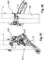
- FIG. 37-44 A third preferred embodiment of a bicycle derailleur 510 in accordance with the invention is illustrated in figures 37-44 , in which elements structurally or functionally equivalent to those already described with reference to the first embodiment of the bicycle derailleur 110 of the invention of figures 23-28 are indicated with the same reference numeral.
- the derailleur 510 is fixed to a tubular element 150 of the bicycle, in particular to the seat tube of the frame.
- the bicycle component 510 comprises a removable clamping device 520 for fixing to the tubular element 150.
- the removable clamping device 520 comprises a plurality of clamping segments configured to be arranged around the entire circumference of the tubular element 150 and to be removably clamped onto it.
- connection systems comprise hinges and a removable fastener 40.
- connection systems define hinging axes, parallel to one another along the direction Y according to which the tubular element 150 is arranged when the bicycle component 510 is fixed thereto; these axes comprise a stable hinging axis for every hinge and a virtual hinging axis for the removable fastener 40.
- the clamping segment 530 is fixed to the main body 12 of the bicycle component, at an appendage portion 530b thereof, equipped with a hole 530c.
- the hole 530c is passed through by a fixing screw to the main body 12.
- the clamping segment 530 extends for an arc between a first end portion and a second end portion opposite the first. At the second end portion the hinge 531 is provided, whereas at the first end portion the clamping segment 530 is provided with a series of hooks 540a that are part of the removable fastener 40.
- the clamping segment 532 extends for an arc between a first end portion and a second end portion opposite the first, and is provided at the opposite end portions with the hinges 531 and 533, respectively.
- the clamping segment 534 extends for an arc between a first end portion and a second end portion opposite the first, and is connected to the clamping segment 532 through the hinge 533, arranged at an intermediate area of the clamping segment 532 and at the first end portion of the clamping segment 534.
- the clamping segment 536 extends between a first end portion and a second end portion opposite the first, and is connected to the clamping segment 534 through the hinge 535, arranged at the second end portion of the clamping segment 534 and at the first end portion of the clamping segment 536.
- the clamping segment 536 is provided at the second end portion with a counter-hook 40b that forms part of the removable fastener 40.
- the clamping device 520 is capable of taking up at least three configurations.
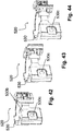
- a first configuration is a clamped configuration ( figures 37-39 and 42 ), wherein the removable fastener 40 is closed and the clamping segments 530, 532, 534 and 536 are arranged in succession substantially defining a minimum closed line, the hinging axes are all arranged close to such a minimum closed line, and the clamping device 520 is clamped when applied to the tubular element;
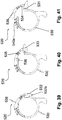
- a second configuration is an open configuration ( figures 40, 41 , 43, 44 ), wherein the removable fastener 40 is open and the clamping segments 530, 532, 534 and 536 are arranged at least partially far from the minimum closed line, at least one of the hinging axes is far from the minimum closed line, and the clamping device 520 can be positioned around the tubular element.
- a third configuration is an intermediate configuration (not illustrated in the figures but clear from what has been described), wherein the removable fastener 40 is closed and the clamping segments 530, 532, 534 and 536 are arranged at least partially far from the minimum closed line, at least one of the hinging axes is far from the minimum closed line, and the clamping device 520 is not clamped when applied to the tubular element.
- the clamping segment 532 is arranged at least partially juxtaposed over the clamping segment 530. In particular, the clamping segment 532 rests on the clamping segment 530.
- the clamping segment 532 comprises an actuating end portion 532a.
- the clamping segment 534 has adjustable length.
- the clamping segment 534 comprises a screw/nut screw coupling between two parts thereof.
- the ways of using the clamping device 520 of the component 510 are clear from what has been described.
- the fastener 40 is closed (fastening the counter-hook 40b to one of the hooks 540a), reaching the intermediate configuration; finally, by acting on the end 532a of the clamping segment 532 in the direction to take the latter above and against the clamping segment 530, carrying the clamping segment 536 with it, the clamping condition is reached.
- the component 510 is locked on the tubular element of the bicycle in a secure and stable manner.
- the hook 540a it is possible to fix the component 510 to tubular elements having a different diameter, within a range dependent on the number of hooks 540a.
- both the mounting and the dismounting are simple and quick.
Landscapes
- Engineering & Computer Science (AREA)
- Mechanical Engineering (AREA)
- General Engineering & Computer Science (AREA)
- Chemical & Material Sciences (AREA)
- Combustion & Propulsion (AREA)
- Transportation (AREA)
- Clamps And Clips (AREA)
- Motorcycle And Bicycle Frame (AREA)
Abstract
Description
- The present invention relates to a bicycle component comprising a removable clamping device for fixing to a tubular element of the bicycle. The bicycle component comprises a main body having a rear surface configured to be associated with the tubular element.
- The invention has a preferred application in the field of racing bicycles.
- In the rest of the description and claims reference will be made to the non-limiting examples of a bicycle component such as a control assembly of bicycle handlebars, to be associated with a tubular element such as a handlebar tube, and a derailleur, to be associated with a tubular element such as a tube of the frame, in particular with the seat tube of the frame (i.e. that which supports the saddle tube of the bicycle at the top).
- In order to associate the aforementioned bicycle component with the tubular element of the bicycle, a removable clamping device is used, which typically comprises an annular strap element, fixed to the main body of the bicycle component and wrapping around the tubular element of the bicycle. The strap, typically metallic, is clamped through the screwing of a nut on a screw, so as to securely tighten together two substantially facing end portions of the strap.
- The mounting operations of the aforementioned bicycle component include the positioning of the screw and the screwing of the nut, and take a certain amount of time.
-
US 2015/0096402 andUS 2015/0000452 show removable clamping devices that comprise an annular element able to be clamped through a screw. - The technical problem at the basis of the present invention is that of providing a bicycle component comprising a removable clamping device for fixing to a tubular element of the bicycle, which ensures quick mounting and dismounting of the bicycle component from the tubular element of the bicycle, at the same time ensuring secure and reliable clamping.
- The present invention therefore relates to a bicycle component comprising a main body and a removable clamping device for fixing to a tubular element of the bicycle, wherein the removable clamping device comprises a plurality of clamping segments configured to be arranged around the entire circumference of the tubular element of the bicycle and to be removably clamped onto it, characterized in that there are at least three clamping segments, connected together in succession in pairs by at least three connection systems, wherein the connection systems comprise at least one hinge and at least one removable fastener.
- Advantageously, the aforementioned removable clamping device makes it possible to obtain quick mounting and dismounting of the bicycle component from the tubular element of the bicycle, through the clamping of the at least three clamping segments through the at least one removable fastener. In particular, the clamping is provided by the fastening of the at least one removable fastener between two clamping segments in succession. Such clamping has proven secure and reliable.
- Preferably, the connection systems define hinging axes, parallel to one another along a direction according to which the tubular element is intended to be arranged when the bicycle component is fixed thereto, the hinging axes comprising a stable hinging axis for every hinge and a virtual hinging axis for every removable fastener. Under the expression virtual hinging it is meant that there is a hinging axis only when the fastening is closed, whereas the hinging axis disappears when the fastening is open, with its parts separated from one another.
- In accordance with preferred features of the invention, the clamping device is capable of taking up at least three configurations:
- i) a clamped configuration, wherein:
- the removable fastener is closed and the clamping segments are arranged in succession substantially defining a minimum closed line,
- the hinging axes are all arranged close to such a minimum closed line, and
- the clamping device is clamped when applied to the tubular element;
- ii) an open configuration, wherein:
- the removable fastener is open and the clamping segments are arranged at least partially far from the minimum closed line,
- at least one of the hinging axes is far from the minimum closed line, and
- the clamping device can be positioned around the tubular element;
- iii) an intermediate configuration, wherein:
- the removable fastener is closed and the clamping segments are arranged at least partially far from the minimum closed line,
- at least one of the hinging axes is far from the minimum closed line, and
- the clamping device is not clamped when applied to the tubular element.
- Preferably, in a clamped configuration of the clamping device, when the bicycle component is fixed to the tubular element of the bicycle, there is surface abutment of the clamping device and of a rear surface of the main body at the tubular element.
- Advantageously, the surface abutment at the tubular element increases the friction and stably locks the bicycle component on the tubular element.
- Preferably, in a clamped configuration of the clamping device, one of the clamping segments is arranged at least partially juxtaposed over an adjacent clamping segment.
- Advantageously, such a juxtaposed clamping segment has the effect of tightening the remaining clamping segments around the tubular element.
- In an embodiment of the invention, the clamping segment arranged at least partially juxtaposed is rested on the adjacent clamping segment.
- In another embodiment of the invention, the clamping segment arranged at least partially juxtaposed is at least partially recessed in a seat formed in the adjacent clamping segment.
- Advantageously, in the latter case, the external space occupied by the clamping device is extremely small.
- Preferably, the clamping segment arranged at least partially juxtaposed comprises an actuating end portion.
- Preferably, at least one of the clamping segments is fixed to the main body of the bicycle component.
- In a preferred embodiment of the invention, at least one of the clamping segments has adjustable length.
- Advantageously, in this way it is possible to adjust the clamping force of the clamping segments around the tubular element.
- Preferably, the at least one of the clamping segments with adjustable length comprises a screw/nut screw coupling between two parts thereof.
- Preferably, one of the clamping segments has a fastening end portion comprising a plurality of hooks.
- Advantageously, in this way it is possible to possibly adapt the clamping device to tubular elements of different size, as well as to adjust the clamping force of the clamping segments around the tubular element.
- In a first preferred embodiment of the invention, there are three clamping segments, there are two hinges and there is one removable fastener, wherein:
- a first of the three clamping segments is fixed to the main body of the bicycle component, extending for an arc between a first end and a second end opposite the first, provided at the first end with a hook, part of the removable fastener;
- a second of the three clamping segments, extending between a first end and a second end opposite the first, connected to the first clamping segment through a first of the two hinges, arranged at the second end of the first clamping segment and at the first end of the second clamping segment;
- a third of the three clamping segments, extending for an arc between a first end and a second end opposite the first, connected to the second clamping segment through a second of the two hinges, arranged at the second end of the second clamping segment and at an intermediate area of the third clamping segment, and provided at the second end with a counter-hook, part of the removable fastener.
- In a second preferred embodiment of the invention, there are five clamping segments, there are at least three hinges and there is one removable fastener, wherein:
- a first of the five clamping segments is fixed to the main body of the bicycle component, extending for an arc between a first end and a second end opposite the first, provided at the first end with a hook, part of the removable fastener;
- a second of the five clamping segments, extending between a first end and a second end opposite the first, connected to the first clamping segment through a first of the at least three hinges, arranged at the second end of the first clamping segment and at the first end of the second clamping segment;
- a third of the five clamping segments, extending for an arc between a first end and a second end opposite the first, connected to the second clamping segment through a second of the at least three hinges, arranged at the second end of the second clamping segment and at the second end of the third clamping segment;
- a fourth of the five clamping segments, extending for an arc between a first end and a second end opposite the first, connected to the third clamping segment at an intermediate area of the third clamping segment;
- a fifth of the five clamping segments, extending between a first end and a second end opposite the first, connected to the fourth clamping segment through a third of the at least three hinges, arranged at the second end of the fourth clamping segment and at the first end of the fifth clamping segment, and provided at the second end with a counter-hook, part of the removable fastener.
- Preferably, the at least three hinges comprise a fourth hinge, between the third and the fourth clamping segment.
- More preferably, the bicycle component according to the invention comprises:
- a perforated bush fixed to the third clamping segment at its intermediate area;
- a threaded head of the first end of the fourth clamping segment, inserted through the perforated bush;
- a threaded nut in adjustable screwing engagement on the threaded head so as to keep it engaged with the perforated bush.
- Even more preferably, the at least three hinges comprise a fourth hinge, between the third clamping segment and the perforated bush.
- In a third preferred embodiment of the invention, there are four clamping segments, there are at least three hinges and there is one removable fastener, wherein:
- a first of the four clamping segments is fixed to the main body of the bicycle component, extending for an arc between a first end and a second end opposite the first, provided at the first end with a series of hooks, part of the removable fastener;
- a second of the four clamping segments, extending between a first end and a second end opposite the first, connected to the first clamping segment through a first of the three hinges, arranged at the second end of the first clamping segment and at the second end of the second clamping segment;
- a third of the four clamping segments, extending for an arc between a first end and a second end opposite the first, connected to the second clamping segment through a second of the at least three hinges, arranged at the second end of the third clamping segment and at an intermediate area of the second clamping segment;
- a fourth of the four clamping segments, extending for an arc between a first end and a second end opposite the first, connected to the third clamping segment through a third of the three hinges, arranged at the second end of the third clamping segment and at the first end of the fourth clamping segment, and provided at the second end with a counter-hook part of the removable fastener.
- Preferably, the component is a control assembly of bicycle handlebars or the component is a derailleur.
- Further features and advantages of the invention will become clearer from the description of preferred embodiments thereof, made with reference to the attached drawings, where:
-
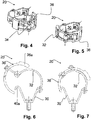
figure 1 is a schematic perspective view of a first preferred embodiment of a control assembly of bicycle handlebars, comprising a removable clamping device for fixing to a tubular element of the bicycle, in accordance with the present invention; -
figure 2 is a schematic perspective view of the removable clamping device offigure 1 , in an open configuration; -
figure 3 is a schematic perspective view of the removable clamping device offigure 1 , in a clamped configuration; -
figure 4 is a schematic perspective view of the removable clamping device offigure 1 , in an open configuration, taken from a different point of view with respect tofigure 2 ; -
figure 5 is a schematic perspective view of the removable clamping device offigure 1 , in a clamped configuration, taken from a different point of view with respect tofigure 3 ; -
figure 6 is a schematic plan view of the removable clamping device offigure 1 , in an open configuration; -
figure 7 is a schematic plan view of the removable clamping device offigure 1 , in a clamped configuration; -
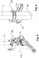
figure 8 is a schematic perspective view of a first preferred embodiment of a bicycle derailleur, comprising a removable clamping device for fixing to a tubular element of the bicycle (also shown), in accordance with the present invention; -
figure 9 is a schematic perspective view of the bicycle derailleur offigure 8 , taken from a different point of view with respect tofigure 8 ; -
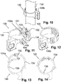
figure 10 is a schematic perspective view of a part of the bicycle derailleur offigure 8 ; -
figure 11 is a schematic perspective view of the removable clamping device offigure 8 , in an open configuration; -
figure 12 is a schematic perspective view of the removable clamping device offigure 8 , in a clamped configuration; -
figure 13 is a schematic plan view of the removable clamping device offigure 8 , in an open configuration; -
figure 14 is a schematic plan view of the removable clamping device offigure 8 , in a clamped configuration; -
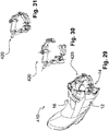
figure 15 is a schematic perspective view of a second preferred embodiment of a control assembly of bicycle handlebars, comprising a removable clamping device for fixing to a tubular element of the bicycle, in accordance with the present invention; -
figure 16 is a schematic perspective view of the removable clamping device offigure 15 , in an open configuration; -
figure 17 is a schematic perspective view of the removable clamping device offigure 15 , in a clamped configuration; -
figure 18 is a schematic perspective view of the control assembly of bicycle handlebars offigure 15 , taken from a different point of view with respect tofigure 15 ; -
figure 19 is a schematic perspective view of the removable clamping device offigure 18 , in an open configuration; -
figure 20 is a schematic perspective view of the removable clamping device offigure 18 , in a clamped configuration; -
figure 21 is a schematic plan view of the removable clamping device offigure 15 , in a clamped configuration; -
figure 22 is a schematic plan view of the removable clamping device offigure 15 , in an open configuration; -
figure 23 is a schematic perspective view of a second preferred embodiment of a bicycle derailleur, comprising a removable clamping device for fixing to a tubular element of the bicycle (also shown), in accordance with the present invention; -
figure 24 is a schematic perspective view of the bicycle derailleur offigure 23 , taken from a different point of view with respect tofigure 23 ; -
figure 25 is a schematic perspective view of the removable clamping device offigure 23 , in a clamped configuration; -
figure 26 is a schematic perspective view of the removable clamping device offigure 23 , in an intermediate configuration; -
figure 27 is a schematic plan view of the removable clamping device offigure 23 , in a clamped configuration; -
figure 28 is a schematic plan view of the removable clamping device offigure 23 , in an intermediate configuration; -
figure 29 is a schematic perspective view of a third preferred embodiment of a control assembly of bicycle handlebars, comprising a removable clamping device for fixing to a tubular element of the bicycle, in accordance with the present invention; -
figure 30 is a schematic perspective view of the removable clamping device offigure 29 , in an open configuration; -
figure 31 is a schematic perspective view of the removable clamping device offigure 29 , in a clamped configuration; -
figure 32 is a schematic perspective view of the control assembly of bicycle handlebars offigure 29 , taken from a different point of view with respect tofigure 29 ; -
figure 33 is a schematic perspective view of the removable clamping device offigure 32 , in an open configuration; -
figure 34 is a schematic perspective view of the removable clamping device offigure 32 , in a clamped configuration; -
figure 35 is a schematic plan view of the removable clamping device offigure 29 , in a clamped configuration; -
figure 36 is a schematic plan view of the removable clamping device offigure 29 , in an open configuration; -
figure 37 is a schematic perspective view of a third preferred embodiment of a bicycle derailleur, comprising a removable clamping device for fixing to a tubular element of the bicycle (also shown), in accordance with the present invention; -
figure 38 is a schematic perspective view of the bicycle derailleur offigure 37 , taken from a different point of view with respect tofigure 37 ; -
figure 39 is a schematic plan view of the removable clamping device offigure 37 , in a clamped configuration; -
figure 40 is a schematic plan view of the removable clamping device offigure 37 , in an intermediate configuration; -
figure 41 is a schematic plan view of the removable clamping device offigure 37 , in an open configuration; -
figure 42 is a schematic perspective view of the removable clamping device offigure 37 , in a clamped configuration; -
figure 43 is a schematic perspective view of the removable clamping device offigure 37 , in an intermediate configuration; -
figure 44 is a schematic perspective view of the removable clamping device offigure 37 , in an open configuration. - In the figures, preferred embodiments of the invention are shown, some referring to a control assembly of handlebars, others referring to a derailleur. In particular,
reference numerals reference numerals - The control assembly of
handlebars bicycle derailleur - The bicycle component is intended to be fixed to a tubular element of the bicycle.
- In the embodiments wherein the bicycle component is a control assembly of bicycle handlebars, the tubular element is a tube of the bicycle handlebars.
- In the embodiments wherein the bicycle component is a bicycle derailleur, the tubular element is a seat tube of the frame (i.e. that which supports the saddle tube of the bicycle at the top).
- With initial reference to the attached
figures 1-7 ,reference numeral 10 indicates a first preferred embodiment of a control assembly of bicycle handlebars in accordance with the present invention. - As illustrated in
figure 1 , thebicycle component 10 comprises aremovable clamping device 20 for fixing to the tubular element (not illustrated) of the bicycle. - A
main body 12 of thebicycle component 10 has arear surface 14 configured to be associated with the tubular element and an oppositefront surface 16. - The
removable clamping device 20 comprises a plurality of clamping segments configured to be arranged around the entire circumference of the tubular element of the bicycle and to be removably clamped on it. - The clamping segments are connected together in succession in pairs by connection systems, wherein the connection systems comprise hinges and a removable fastener 40.
- The connection systems define hinging axes, parallel to one another along a direction according to which the tubular element is intended to be arranged when the
bicycle component 10 is fixed thereto; the hinging axes comprise a stable hinging axis for every hinge and a virtual hinging axis for the removable fastener 40. - In particular, in this embodiment of the invention, there are four clamping segments, indicated with 30, 32, 34 and 36, and there are three hinges, indicated with 31, 33 and 35.
- The clamping
segment 30 is fixed to themain body 12 of the bicycle component, through apin 30a that is preferably externally threaded, or through a screw screwed into an axial cavity of such a pin, without external threading. As an alternative to the threaded connection just described, the clampingsegment 30 can be fixed to themain body 12 through overmolding. - The clamping
segment 30 is substantially V-shaped, with a first end portion, at which thehinge 31 is provided, and a second opposite end portion where ahook 40a is provided that forms part of the removable fastener 40. - The clamping
segment 32 extends for an arc between a first end portion and a second end portion opposite the first, provided at the opposite end portions with thehinges - The clamping
segment 34 extends between a first end portion and a second end portion opposite the first, and is connected to the clampingsegment 32 through thehinge 33, arranged at the second end portion of the clampingsegment 32 and at the first end portion of the clampingsegment 34. - The clamping
segment 36 extends for an arc between a first end portion and a second end portion opposite the first, and is connected to the clampingsegment 34 through thehinge 35, arranged at the second end portion of the clampingsegment 34 and at an intermediate area of the clampingsegment 36. The clampingsegment 36 is provided at the second end portion with a counter-hook 40b, which forms part of the removable fastener 40. - The clamping
device 20 is capable of taking up at least three configurations. - A first configuration is a clamped configuration (
figures 3 ,5 and 7 ), wherein the removable fastener 40 is closed and the clampingsegments fig. 7 ), the hinging axes are all arranged close to such a minimum closed line, and theclamping device 20 is clamped when applied to the tubular element; - A second configuration is an open configuration (
figures 2 ,4 and 6 ), wherein the removable fastener 40 is open and the clampingsegments clamping device 20 can be positioned around the tubular element; - A third configuration is an intermediate configuration (not illustrated in the figures but obvious from what has been described), wherein the removable fastener 40 is closed and the clamping
segments clamping device 20 is not clamped when applied to the tubular element. - In the clamped configuration of the
clamping device 20, when the bicycle component is fixed to the tubular element of the bicycle, there is surface abutment of theclamping device 20 and of therear surface 14 of themain body 12 at the tubular element. - In the clamped configuration of the
clamping device 20, the clampingsegment 34 is arranged at least partially juxtaposed over the clampingsegment 32. - The clamping
segment 34 arranged at least partially juxtaposed is at least partially recessed in aseat 32a formed in theclamping segment 32. - The clamping
segment 36 comprises anactuating end portion 36a. - The ways of using the
clamping device 20 of thecomponent 10 are clear from what has been described. In order to fix thecomponent 10 to the tubular element of the bicycle, it is necessary to bring theclamping device 20 into its open configuration and arrange it around the tubular element so as to embrace it; at this point, the fastener 40 is closed (by fastening thehook 40a to the counter-hook 40b), reaching the intermediate configuration; finally, by acting on theend 36a of the clampingsegment 36 in the direction to take the latter above and against the clampingsegment 34 and this in turn above and against the clampingsegment 32, the clamping condition is reached. At this point, thecomponent 10 is locked on the tubular element of the bicycle in a secure and stable manner. - If it is wished to then dismount the
component 10 from the tubular element of the bicycle, it is sufficient to carry out the previous operations in reverse. - As can be seen, both the mounting and the dismounting are simple and quick.
- A first preferred embodiment of a
bicycle derailleur 110 in accordance with the invention is illustrated infigures 8-14 , in which elements structurally or functionally equivalent to those already described with reference to the first embodiment of the control assembly ofbicycle handlebars 10 of the invention are indicated with the same reference numeral. - In this preferred embodiment, the
derailleur 110 is fixed to atubular element 150 of the bicycle, in particular to the seat tube of the frame. - As illustrated in
figures 8 and 9 , thebicycle component 110 comprises aremovable clamping device 120 for fixing to thetubular element 150. - The
removable clamping device 120 comprises a plurality of clamping segments configured to be arranged around the entire circumference of thetubular element 150 and to be removably clamped on it. - The clamping segments are connected together in succession in pairs by connection systems, wherein the connection systems comprise hinges and a removable fastener 40.
- The connection systems define hinging axes, parallel to one another along the direction Y according to which the
tubular element 150 is arranged when thebicycle component 110 is fixed thereto; these axes comprise a stable hinging axis for every hinge and a virtual hinging axis for the removable fastener 40. - In particular, in this embodiment of the invention, there are three clamping segments, indicated with 130, 132 and 134, and there are two hinges, indicated with 131 and 133.
- The
clamping segment 130 is fixed to themain body 12 of the bicycle component, at anappendage portion 130b thereof, equipped with ahole 130c. Thehole 130c is passed through by a fixing screw to themain body 12. - The
clamping segment 130 extends for an arc between a first end portion and a second end portion opposite the first, ahook 40a that forms part of the removable fastener 40 being provided at the first end portion. - The
clamping segment 132 extends between a first end portion and a second end portion opposite the first, connected to theclamping segment 130 through ahinge 131, arranged at the second end portion of theclamping segment 130 and at the first end portion of theclamping segment 132. - The
clamping segment 134 extends for an arc between a first end portion and a second end portion opposite the first, and is connected to theclamping segment 132 through thehinge 133, arranged at the second end portion of theclamping segment 132 and at an intermediate area of theclamping segment 134. Theclamping segment 134 is provided at the second end portion with a counter-hook 40b, which forms part of the removable fastener 40. - The
clamping device 120 is capable of taking up at least three configurations: - A first configuration is a clamped configuration (
figures 8, 9 ,10, 12 and 14 ), wherein the removable fastener 40 is closed and the clampingsegments clamping device 120 is clamped when applied to the tubular element; - A second configuration is an open configuration (
figures 11 and 13 ), wherein the removable fastener 40 is open and the clampingsegments clamping device 120 can be positioned around the tubular element. - A third configuration is an intermediate configuration (not illustrated in the figures but obvious from what has been described), wherein the removable fastener 40 is closed and the clamping
segments clamping device 120 is not clamped when applied to the tubular element. - In the clamped configuration of the
clamping device 120, theclamping segment 132 is arranged at least partially juxtaposed over the clampingsegment 130. - The
clamping segment 132 arranged at least partially juxtaposed is at least partially recessed in aseat 130a formed in theclamping segment 130. - The
clamping segment 134 comprises anactuating end portion 134a. - The ways of using the
clamping device 120 of thecomponent 110 are clear from what has been described. In order to fix thecomponent 110 to the tubular element of the bicycle, it is necessary to bring theclamping device 120 into its open configuration and to arrange it around the tubular element so as to embrace it; at this point, the fastener 40 is closed (by fastening thehook 40a to the counter-hook 40b), reaching the intermediate configuration; finally, by acting on theclamping segment 134 in the direction to take it above and against the clampingsegment 132 and this above and against the clampingsegment 130, the clamping condition is reached. At this point, thecomponent 110 is locked on the tubular element of the bicycle in a secure and stable manner. - If it is then wished to dismount the
component 110 from the tubular element of the bicycle, it is sufficient to carry out the previous operations in reverse. - As can be seen, both the mounting and the dismounting are simple and quick.
- A second preferred embodiment of the control assembly of
bicycle handlebars 210 in accordance with the invention is illustrated infigures 15-22 , in which elements structurally or functionally equivalent to those already described with reference to the prima embodiment of the control assembly ofbicycle handlebars 10 of the invention offigures 1-7 are indicated with the same reference numeral. - As illustrated in
figure 15 , thebicycle component 210 comprises aremovable clamping device 220 for fixing to the tubular element (not illustrated) of the bicycle. - A
main body 12 of thebicycle component 210 has arear surface 14 configured to be associated with the tubular element and an oppositefront surface 16. - The
removable clamping device 220 comprises a plurality of clamping segments configured to be arranged around the entire circumference of the tubular element of the bicycle and to be removably clamped on it. - The clamping segments are connected together in succession in pairs by connection systems, wherein the connection systems comprise hinges and a removable fastener 40.
- The connection systems define hinging axes, parallel to one another along a direction according to which the tubular element is intended to be arranged when the
bicycle component 210 is fixed thereto; the hinging axes comprise a stable hinging axis for every hinge and a virtual hinging axis for the removable fastener 40. - In particular, in this embodiment of the invention, there are five clamping segments, indicated with 230, 232, 234, 236 and 238, and there are four hinges, indicated with 231, 233, 235 and 237.
- The
clamping segment 230 is fixed to themain body 12 of the bicycle component, through apin 30a that is preferably externally threaded, or through a screw screwed into an axial cavity of such a pin, without external threading. As an alternative to the threaded connection just described, the clampingsegment 30 can be fixed to themain body 12 through overmolding. - The
clamping segment 230 is substantially V-shaped, with a first end portion, at which thehinge 231 is provided, and a second opposite end portion where ahook 40a that forms part of the removable fastener 40 is provided. - The
clamping segment 232 extends for an arc between a first end portion and a second end portion opposite the first, provided at the opposite end portions with thehinges - The
clamping segment 234 extends between a first end portion and a second end portion opposite the first, and is connected to theclamping segment 232 through thehinge 233, arranged at the second end portion of theclamping segment 232 and at the first end portion of theclamping segment 234. - The
clamping segment 236 extends for an arc between a first end portion and a second end portion opposite the first, and is connected to theclamping segment 234 through ahinge 235, arranged at an intermediate area of theclamping segment 234 and at the first end portion of theclamping segment 236. - The
clamping segment 238 extends between a first end portion and a second end portion opposite the first, and is connected to theclamping segment 236 through ahinge 237, arranged at the second end portion of theclamping segment 236 and at the first end portion of theclamping segment 238. Theclamping segment 238 is provided at the second end portion with a counter-hook 40b that forms part of the removable fastener 40. - The
clamping device 220 is capable of taking up at least three configurations. - A first configuration is a clamped configuration (
figures 15, 17 ,18, 20 and21 ), wherein the removable fastener 40 is closed and the clampingsegments clamping device 220 is clamped when applied to the tubular element; - A second configuration is an open configuration (
figures 16 ,19 and22 ), wherein the removable fastener 40 is open and the clampingsegments clamping device 220 can be positioned around the tubular element. - A third configuration is an intermediate configuration (not illustrated in the figures but obvious from what has been described), wherein the removable fastener 40 is closed and the clamping
segments clamping device 220 is not clamped when applied to the tubular element. - In the clamped configuration of the
clamping device 220, when the bicycle component is fixed to the tubular element of the bicycle, there is surface abutment of theclamping device 220 and of therear surface 14 of themain body 12 at the tubular element. - In the clamped configuration of the
clamping device 220, theclamping segment 234 is arranged at least partially juxtaposed over the clampingsegment 232. In particular, theclamping segment 234 rests on theclamping segment 232. - The
clamping segment 234 comprises anactuating end portion 234a. - The
clamping segment 236 has adjustable length. - The
clamping segment 236 comprises a screw/nut screw coupling between two parts thereof. - In particular, a
perforated bush 260 is fixed to theclamping segment 234 at its intermediate area. - A threaded head of the first end of the
clamping segment 236 is inserted through theperforated bush 260. A threaded nut in screwing engagement is adjustable on the threaded head so as to keep it engaged with theperforated bush 260. - The
hinge 235 is arranged between the clampingsegment 234 and theperforated bush 260. - The ways of using the
clamping device 220 of thecomponent 210 are clear from what has been described. In order to fix thecomponent 210 to the tubular element of the bicycle, it is necessary to take theclamping device 220 into its open configuration and to arrange it around the tubular element so as to embrace it; at this point, it is possible to adjust the width of theclamping device 220, unscrewing or screwing in the threaded head of theclamping segment 236 in thebush 260; thereafter, the fastener 40 is closed (by fastening thehook 40a to the counter-hook 40b), reaching the intermediate configuration; finally, by acting on theend 234a of theclamping segment 234 in the direction to take the latter above and against the clampingsegment 232, carrying theclamping segment 236 above it, the clamping condition is reached. At this point, thecomponent 210 is locked on the tubular element of the bicycle in a secure and stable manner. - If it is then wished to dismount the
component 210 from the tubular element of the bicycle, it is sufficient to carry out the previous operations in reverse. - As can be seen, both the mounting and the dismounting are simple and quick.
- A second preferred embodiment of a
bicycle derailleur 310 in accordance with the invention is illustrated infigures 23-28 , in which elements structurally or functionally equivalent to those already described with reference to the first embodiment of thebicycle derailleur 110 of the invention offigures 8-14 are indicated with the same reference numeral. - In this preferred embodiment, the
derailleur 310 is fixed to atubular element 150 of the bicycle, in particular to the seat tube of the frame. - As illustrated in
figures 23 and 24 , thebicycle component 310 comprises aremovable clamping device 320 for fixing to thetubular element 150. - The
removable clamping device 320 comprises a plurality of clamping segments configured to be arranged around the entire circumference of thetubular element 150 and to be removably clamped on it. - The clamping segments are connected together in succession in pairs by connection systems, wherein the connection systems comprise hinges and a removable fastener 40.
- The connection systems define hinging axes, parallel to one another along the direction Y according to which the
tubular element 150 is arranged when thebicycle component 310 is fixed thereto; these axes comprise a stable hinging axis for every hinge and a virtual hinging axis for the removable fastener 40. - In particular, in this embodiment of the invention, there are five clamping segments, indicated with 330, 332, 334, 336 and 338, and there are four hinges, indicated with 331, 333, 335 and 337.
- The
clamping segment 330 is fixed to themain body 12 of the bicycle component, at anappendage portion 330b thereof, equipped with ahole 330c. Thehole 330c is passed through by a fixing screw to themain body 12. - The
clamping segment 330 extends for an arc between a first end portion and a second end portion opposite the first, ahook 40a that forms part of the removable fastener 40 being provided at the first end portion. - The
clamping segment 332 extends for an arc between a first end portion and a second end portion opposite the first, provided at the opposite end portions with thehinges 331 and 333, respectively. - The
clamping segment 334 extends between a first end portion and a second end portion opposite the first, and is connected to theclamping segment 332 through thehinge 333, arranged at the second end portion of theclamping segment 332 and at the first end portion of theclamping segment 334. - The
clamping segment 336 extends for an arc between a first end portion and a second end portion opposite the first, and is connected to theclamping segment 334 through ahinge 335, arranged at an intermediate area of theclamping segment 334 and at the first end portion of theclamping segment 336. - The clamping segment 338 extends between a first end portion and a second end portion opposite the first, and is connected to the
clamping segment 336 through ahinge 337, arranged at the second end portion of theclamping segment 336 and at the first end portion of the clamping segment 338. Theclamping segment 238 is provided at the second end portion with a counter-hook 40b that forms part of the removable fastener 40. - The
clamping device 320 is capable of taking up at least three configurations. - A first configuration is a clamped configuration (
figures 23, 24 ,25 and 27 ), wherein the removable fastener 40 is closed and the clampingsegments clamping device 320 is clamped when applied to the tubular element; - A second configuration is an open configuration (not illustrated in the figures but clear from what has been described), wherein the removable fastener 40 is open and the clamping
segments clamping device 320 can be positioned around the tubular element. - A third configuration is an intermediate configuration (
figures 26 and 28 ), wherein the removable fastener 40 is closed and the clampingsegments clamping device 320 is not clamped when applied to the tubular element. - In the clamped configuration of the
clamping device 220, theclamping segment 334 is arranged at least partially juxtaposed over the clampingsegment 332. In particular, theclamping segment 334 is rested on theclamping segment 232. - The
clamping segment 334 comprises anactuating end portion 334a. - The
clamping segment 336 has adjustable length. - The
clamping segment 336 comprises a screw/nut screw coupling between two parts thereof. - In particular, a
perforated bush 360 is fixed to theclamping segment 334 at its intermediate area. - A threaded head of the first end of the
clamping segment 336 is inserted through theperforated bush 360. A threaded nut in screwing engagement is adjustable on the threaded head so as to keep it engaged with theperforated bush 360. - The
hinge 335 is arranged between the clampingsegment 334 and theperforated bush 360. - The ways of using the
clamping device 320 of thecomponent 310 are clear from what has been described. In order to fix thecomponent 310 to the tubular element of the bicycle, it is necessary to take theclamping device 320 into its open configuration and to arrange it around the tubular element so as to embrace it; at this point, it is possible to adjust the width of theclamping device 320, by unscrewing or screwing the threaded head of theclamping segment 336 in thebush 360; thereafter, the fastener 40 is closed (by fastening thehook 40a to the counter-hook 40b), reaching the intermediate configuration; finally, by acting on theend 334a of theclamping segment 334 in the direction to take the latter above and against the clampingsegment 332, carrying theclamping segment 336 with it, the clamping condition is reached. At this point, thecomponent 310 is locked on the tubular element of the bicycle in a secure and stable manner. - If it is then wished to dismount the
component 310 from the tubular element of the bicycle, it is sufficient to carry out the previous operations in reverse. - As can be seen, both the mounting and the dismounting are simple and quick.
- A third preferred embodiment of the control assembly of
bicycle handlebars 410 in accordance with the invention is illustrated infigures 29-36 , in which elements structurally or functionally equivalent to those already described with reference to the first embodiment of the control assembly ofbicycle handlebars 10 of the invention offigures 15-22 are indicated with the same reference numeral. - As illustrated in
figure 29 , thebicycle component 410 comprises aremovable clamping device 420 for fixing to the tubular element (not illustrated) of the bicycle. - A
main body 12 of thebicycle component 410 has arear surface 14 configured to be associated with the tubular element and an oppositefront surface 16. - The
removable clamping device 420 comprises a plurality of clamping segments configured to be arranged around the entire circumference of the tubular element of the bicycle and to be removably clamped on it. - The clamping segments are connected together in succession in pairs by connection systems, wherein the connection systems comprise hinges and a removable fastener 40.
- The connection systems define hinging axes, parallel to one another along a direction according to which the tubular element is intended to be arranged when the
bicycle component 410 is fixed thereto; the hinging axes comprise a stable hinging axis for every hinge and a virtual hinging axis for the removable fastener 40. - In particular, in this embodiment of the invention, there are six clamping segments, indicated with 430, 432, 434, 436, 438 and 442, and there are five hinges, indicated with 431, 433, 435, 437 and 439.
- The
clamping segment 430 is fixed to themain body 12 of the bicycle component, through apin 30a that is preferably externally threaded, or through a screw screwed into an axial cavity of such a pin, without external threading. As an alternative to the threaded connection just described, the clampingsegment 30 can be fixed to themain body 12 through overmolding. - The
clamping segment 430 is substantially V-shaped, with a first end portion at which thehinge 431 is provided and a second opposite end portion at which thehinge 439 is provided. - The
clamping segment 432 extends for an arc between a first end portion and a second end portion opposite the first, and is provided at the opposite end portions with thehinges - The
clamping segment 434 extends between a first end portion and a second end portion opposite the first, and is connected to theclamping segment 432 through thehinge 433, arranged at the second end portion of theclamping segment 432 and at the first end portion of theclamping segment 434. - The
clamping segment 436 extends for an arc between a first end portion and a second end portion opposite the first, and is connected to theclamping segment 434 through ahinge 435, arranged at an intermediate area of theclamping segment 434 and at the first end portion of theclamping segment 436. - The
clamping segment 238 extends between a first end portion and a second end portion opposite the first, and is connected to theclamping segment 436 through ahinge 437, arranged at the second end portion of theclamping segment 436 and at the first end portion of theclamping segment 438. Theclamping segment 438 is provided at the second end portion with a counter-hook 40b that forms part of the removable fastener 40. - The
clamping segment 442 extends for an arc between a first end portion and a second end portion opposite the first, and is provided at the first end portion with a series ofhooks 440a that are part of the removable fastener 40. Theclamping segment 442 is connected, at its second end portion, to theclamping segment 430 through thehinge 439. - The
clamping device 420 is capable of taking up at least three configurations. - A first configuration is a clamped configuration (
figures 29, 31 ,32, 34 and35 ), wherein the removable fastener 40 is closed and the clampingsegments clamping device 420 is clamped when applied to the tubular element. - A second configuration is an open configuration (
figures 30 ,33 and36 ), wherein the removable fastener 40 is open and the clampingsegments clamping device 420 can be positioned around the tubular element. - A third configuration is an intermediate configuration (not illustrated in the figures but clear from what has been described), wherein the removable fastener 40 is closed and the clamping
segments clamping device 420 is not clamped when applied to the tubular element. - In the clamped configuration of the
clamping device 420, when the bicycle component is fixed to the tubular element of the bicycle, there is surface abutment of theclamping device 420 and of therear surface 14 of themain body 12 at the tubular element. - In the clamped configuration of the
clamping device 420, theclamping segment 434 is arranged at least partially juxtaposed over the clampingsegment 432. In particular, theclamping segment 434 rests on theclamping segment 432. - The
clamping segment 434 comprises anactuating end portion 434a. - The
clamping segment 436 has adjustable length. - The
clamping segment 436 comprises a screw/nut screw coupling between two parts thereof. - The ways of using the
clamping device 420 of thecomponent 410 are clear from what has been described. In order to fix thecomponent 410 to the tubular element of the bicycle, it is necessary to take theclamping device 420 into its open configuration and to arrange it around the tubular element so as to embrace it; at this point, the fastener 40 is closed (by fastening the counter-hook 40b to one of thehooks 440a), reaching the intermediate configuration; finally, by acting on theend 434a of theclamping segment 434 in the direction to take the latter above and against the clampingsegment 432, carrying theclamping segment 436 with it, the clamping condition is reached. At this point, thecomponent 410 is locked on the tubular element of the bicycle in a secure and stable manner. By suitably selecting thehook 440a, it is possible to fix thecomponent 410 to tubular elements having a different diameter, within a range dependent on the number ofhooks 440a. - If it is then wished to dismount the
component 410 from the tubular element of the bicycle, it is sufficient to carry out the previous operations in reverse. - As can be seen, both the mounting and the dismounting are simple and quick.
- A third preferred embodiment of a
bicycle derailleur 510 in accordance with the invention is illustrated infigures 37-44 , in which elements structurally or functionally equivalent to those already described with reference to the first embodiment of thebicycle derailleur 110 of the invention offigures 23-28 are indicated with the same reference numeral. - In this preferred embodiment, the
derailleur 510 is fixed to atubular element 150 of the bicycle, in particular to the seat tube of the frame. - As illustrated in
figures 37 and 38 , thebicycle component 510 comprises aremovable clamping device 520 for fixing to thetubular element 150. - The
removable clamping device 520 comprises a plurality of clamping segments configured to be arranged around the entire circumference of thetubular element 150 and to be removably clamped onto it. - The clamping segments are connected together in succession in pairs by connection systems, wherein the connection systems comprise hinges and a removable fastener 40.
- The connection systems define hinging axes, parallel to one another along the direction Y according to which the
tubular element 150 is arranged when thebicycle component 510 is fixed thereto; these axes comprise a stable hinging axis for every hinge and a virtual hinging axis for the removable fastener 40. - In particular, in this embodiment of the invention, there are four clamping segments, indicated with 530, 532, 534 and 536, and there are three hinges, indicated with 331, 333 and 335.
- The
clamping segment 530 is fixed to themain body 12 of the bicycle component, at anappendage portion 530b thereof, equipped with ahole 530c. Thehole 530c is passed through by a fixing screw to themain body 12. - The
clamping segment 530 extends for an arc between a first end portion and a second end portion opposite the first. At the second end portion thehinge 531 is provided, whereas at the first end portion theclamping segment 530 is provided with a series ofhooks 540a that are part of the removable fastener 40. - The
clamping segment 532 extends for an arc between a first end portion and a second end portion opposite the first, and is provided at the opposite end portions with thehinges - The
clamping segment 534 extends for an arc between a first end portion and a second end portion opposite the first, and is connected to theclamping segment 532 through thehinge 533, arranged at an intermediate area of theclamping segment 532 and at the first end portion of theclamping segment 534. - The
clamping segment 536 extends between a first end portion and a second end portion opposite the first, and is connected to theclamping segment 534 through thehinge 535, arranged at the second end portion of theclamping segment 534 and at the first end portion of theclamping segment 536. Theclamping segment 536 is provided at the second end portion with a counter-hook 40b that forms part of the removable fastener 40. - The
clamping device 520 is capable of taking up at least three configurations. - A first configuration is a clamped configuration (
figures 37-39 and42 ), wherein the removable fastener 40 is closed and the clampingsegments clamping device 520 is clamped when applied to the tubular element; - A second configuration is an open configuration (
figures 40, 41 ,43, 44 ), wherein the removable fastener 40 is open and the clampingsegments clamping device 520 can be positioned around the tubular element. - A third configuration is an intermediate configuration (not illustrated in the figures but clear from what has been described), wherein the removable fastener 40 is closed and the clamping
segments clamping device 520 is not clamped when applied to the tubular element. - In the clamped configuration of the
clamping device 520, theclamping segment 532 is arranged at least partially juxtaposed over the clampingsegment 530. In particular, theclamping segment 532 rests on theclamping segment 530. - The
clamping segment 532 comprises anactuating end portion 532a. - The
clamping segment 534 has adjustable length. - The
clamping segment 534 comprises a screw/nut screw coupling between two parts thereof. - The ways of using the
clamping device 520 of thecomponent 510 are clear from what has been described. In order to fix thecomponent 510 to the tubular element of the bicycle, it is necessary to take theclamping device 520 into its open configuration and arrange it around the tubular element so as to embrace it; at this point, the fastener 40 is closed (fastening the counter-hook 40b to one of thehooks 540a), reaching the intermediate configuration; finally, by acting on theend 532a of theclamping segment 532 in the direction to take the latter above and against the clampingsegment 530, carrying theclamping segment 536 with it, the clamping condition is reached. At this point, thecomponent 510 is locked on the tubular element of the bicycle in a secure and stable manner. By suitably selecting thehook 540a, it is possible to fix thecomponent 510 to tubular elements having a different diameter, within a range dependent on the number ofhooks 540a. - If it is then wished to dismount the
component 510 from the tubular element of the bicycle, it is sufficient to carry out the previous operations in reverse. - As can be seen, both the mounting and the dismounting are simple and quick.
- Of course, those skilled in the art can bring numerous modifications and variants to the present invention in order to satisfy specific and contingent requirements, all of which are in any case encompassed by the scope of protection defined by the following claims.
Claims (15)
- Bicycle component (10, 110, 210, 310, 410, 510) comprising a main body (12) and a removable clamping device (20, 120, 220, 320, 420, 520) for fixing to a tubular element (150) of the bicycle, wherein the removable clamping device (20, 120, 220, 320, 420, 520) comprises a plurality of clamping segments (30, 32, 34, 36, 130, 132, 134, 230, 232, 234, 236, 238, 330, 332, 334, 336, 338, 430, 432, 434, 436, 438, 442, 530, 532, 534, 536) configured to be arranged around the entire circumference of the tubular element (150) of the bicycle and to be removably clamped on it, characterized in that there are at least three clamping segments (30, 32, 34, 36, 130, 132, 134, 230, 232, 234, 236, 238, 330, 332, 334, 336, 338, 430, 432, 434, 436, 438, 442, 530, 532, 534, 536), connected together in succession in pairs by at least three connection systems, wherein the connection systems comprise at least one hinge (31, 33, 35, 131, 133, 231, 233, 235, 237, 331, 333, 335, 337, 431, 433, 435, 437, 439, 531, 533, 535) and at least one removable fastener (40).
- Bicycle component (10, 110, 210, 310, 410, 510) according to claim 1, wherein the connection systems define hinging axes, parallel to one another along a direction (Y) according to which the tubular element (150) is intended to be arranged when the bicycle component (10, 110) is fixed thereto, the hinging axes comprising a stable hinging axis for every hinge (31, 33, 35, 131, 133, 231, 233, 235, 237, 331, 333, 335, 337, 431, 433, 435, 437, 439, 531, 533, 535) and a virtual hinging axis for every removable fastener (40).
- Bicycle component (10, 110, 210, 310, 410, 510) according to claim 2, wherein the clamping device (20, 120, 220, 320, 420, 520) is capable of taking up at least three configurations:i) a clamped configuration, in which:the removable fastener (40) is closed and the clamping segments (30, 32, 34, 36, 130, 132, 134, 230, 232, 234, 236, 238, 330, 332, 334, 336, 338, 430, 432, 434, 436, 438, 442, 530, 532, 534, 536) are arranged in succession substantially defining a minimum closed line,the hinging axes are all arranged close to such a minimum closed line, andthe clamping device (20, 120, 220, 320, 420, 520) is clamped when applied to the tubular element (150);ii) an open configuration, in which:the removable fastener (40) is open and the clamping segments (30, 32, 34, 36, 130, 132, 134, 230, 232, 234, 236, 238, 330, 332, 334, 336, 338, 430, 432, 434, 436, 438, 442, 530, 532, 534, 536) are arranged at least partially far from the minimum closed line,at least one of the hinging axes is far from the minimum closed line, andthe clamping device (20, 120, 220, 320, 420, 520) can be positioned around the tubular element (150);iii) an intermediate configuration, in which:the removable fastener (40) is closed and the clamping segments (30, 32, 34, 36, 130, 132, 134, 230, 232, 234, 236, 238, 330, 332, 334, 336, 338, 430, 432, 434, 436, 438, 442, 530, 532, 534, 536) are arranged at least partially far from the minimum closed line,at least one of the hinging axes is far from the minimum closed line, andthe clamping device (20, 120, 220, 320, 420, 520) is not clamped when applied to the tubular element (150).
- Bicycle component (10, 110, 210, 310, 410, 510) according to any of the previous claims, wherein - in a clamped configuration of the clamping device (20, 120, 220, 320, 420, 520), when the bicycle component (10, 110) is fixed to the tubular element (150) of the bicycle - there is surface abutment of the clamping device (20, 120, 220, 320, 420, 520) and of a rear surface (14) of the main body (12) at the tubular element (150).
- Bicycle component (10, 110, 210, 310, 410, 510) according to any of the previous claims, wherein - in a clamped configuration of the clamping device (20, 120, 220, 320, 420, 520) - one (34, 132, 234, 334, 434, 532) of the clamping segments is arranged at least partially juxtaposed over an adjacent clamping segment (32, 130, 232, 332, 432, 530).
- Bicycle component (10, 110, 210, 310, 410, 510) according to claim 5, wherein the clamping segment (34, 132, 234, 334, 434, 532) arranged at least partially juxtaposed is at least partially recessed in a seat (32a, 130a) formed in the adjacent clamping segment (32, 130, 232, 332, 432, 530).
- Bicycle component (10, 110, 210, 310, 410, 510) according to any of claims 5 to 6, wherein the clamping segment (34, 132, 234, 334, 434, 532) arranged at least partially juxtaposed comprises an actuating end portion (234a, 334a, 434a, 532a) .
- Bicycle component (10, 110, 210, 310, 410, 510) according to any of the previous claims, wherein at least one (30, 130, 230, 330, 430, 530) of the clamping segments is fixed to the main body (12) of the bicycle component (10, 110, 210, 310, 410, 510).
- Bicycle component (410, 510) according to any of the previous claims, wherein one (442, 530) of the clamping segments has a fastening end portion comprising a plurality of hooks (440a, 540a) .
- Bicycle component (110) according to claim 3, wherein there are three clamping segments (130, 132, 134), there are two hinges (131, 133) and there is at least one removable fastener (40), wherein:a first (130) of the three clamping segments is fixed to the main body (12) of the bicycle component (110), extending for an arc between a first end and a second end opposite the first, provided at the first end with a hook (40a) part of the removable fastener (40);a second (132) of the three clamping segments, extending between a first end and a second end opposite the first, connected to the first clamping segment (130) through a first (131) of the two hinges, arranged at the second end of the first clamping segment (130) and at the first end of the second clamping segment (132);a third (134) of the three clamping segments, extending for an arc between a first end and a second end opposite the first, connected to the second clamping segment (132) through a second (133) of the two hinges, arranged at the second end of the second clamping segment (132) and at an intermediate area of the third clamping segment (134), and provided at the second end with a counter-hook (40b) part of the removable fastener (40).
- Bicycle component (310) according to claim 3, wherein there are five clamping segments (330, 332, 334, 336, 338), there are at least three hinges (331, 333, 335, 337) and there is at least one removable fastener (40), wherein:a first (330) of the five clamping segments is fixed to the main body (12) of the bicycle component (310), extending for an arc between a first end and a second end opposite the first, provided at the first end with a hook (40a) part of the removable fastener (40);a second (332) of the five clamping segments, extending between a first end and a second end opposite the first, connected to the first clamping segment (330) through a first (331) of the at least three hinges, arranged at the second end of the first clamping segment (330) and at the first end of the second clamping segment (332);a third (334) of the five clamping segments, extending for an arc between a first end and a second end opposite the first, connected to the second clamping segment (332) through a second (333) of the at least three hinges, arranged at the second end of the second clamping segment (332) and at the second end of the third clamping segment (334);a fourth (336) of the five clamping segments, extending for an arc between a first end and a second end opposite the first, connected to the third clamping segment (334) at an intermediate area of the third clamping segment (334);a fifth (338) of the five clamping segments, extending between a first end and a second end opposite the first, connected to the fourth clamping segment (336) through a third (337) of the at least three hinges, arranged at the second end of the fourth clamping segment (336) and at the first end of the fifth clamping segment (338), and provided at the second end with a counter-hook (40b) part of the removable fastener (40).
- Bicycle component (310) according to claim 11, wherein the at least three hinges comprise a fourth hinge (335), between the third (334) and the fourth clamping segment (336).
- Bicycle component (310) according to claim 11 or 12, comprising:a perforated bush (360) fixed to the third clamping segment (334) at its intermediate area;a threaded head of the first end of the fourth clamping segment (336), inserted through the perforated bush;a threaded nut in adjustable screwing engagement on the threaded head so as to keep it engaged with the perforated bush (360) .
- Bicycle component (510) according to claim 3, wherein there are four clamping segments (530, 532, 534, 536), there are at least three hinges (531, 533, 535) and there is at least one removable fastener (40), wherein:a first (530) of the four clamping segments is fixed to the main body (12) of the bicycle component (510), extending for an arc between a first end and a second end opposite the first, provided at the first end with a series of hooks (540a) part of the removable fastener (40);a second (532) of the four clamping segments, extending between a first end and a second end opposite the first, connected to the first clamping segment (530) through a first (531) of the three hinges, arranged at the second end of the first clamping segment (530) and at the second end of the second clamping segment (532);a third (534) of the four clamping segments, extending for an arc between a first end and a second end opposite the first, connected to the second clamping segment (532) through a second (533) of the at least three hinges, arranged at the second end of the third clamping segment (534) and at an intermediate area of the second clamping segment (532);a fourth (536) of the four clamping segments, extending for an arc between a first end and a second end opposite the first, connected to the third clamping segment (534) through a third (535) of the three hinges, arranged at the second end of the third clamping segment (534) and at the first end of the fourth clamping segment (536), and provided at the second end of a counter-hook (40b) part of the removable fastener (40).
- Bicycle component (10, 110, 210, 310, 410, 510) according to any of the previous claims, wherein the component is a control assembly of bicycle handlebars (10) or the component is a derailleur (110).
Applications Claiming Priority (1)
| Application Number | Priority Date | Filing Date | Title |
|---|---|---|---|
| IT102017000090937A IT201700090937A1 (en) | 2017-08-07 | 2017-08-07 | Bicycle component comprising a removable clamping device for fixing to a tubular element of the bicycle |
Publications (1)
| Publication Number | Publication Date |
|---|---|
| EP3441294A1 true EP3441294A1 (en) | 2019-02-13 |
Family
ID=60451134
Family Applications (1)
| Application Number | Title | Priority Date | Filing Date |
|---|---|---|---|
| EP18186307.7A Withdrawn EP3441294A1 (en) | 2017-08-07 | 2018-07-30 | Bicycle component comprising a removable clamping device for fixing to a tubular element of the bicycle |
Country Status (6)
| Country | Link |
|---|---|
| US (1) | US20190040994A1 (en) |
| EP (1) | EP3441294A1 (en) |
| JP (1) | JP2019077431A (en) |
| CN (1) | CN109383683A (en) |
| IT (1) | IT201700090937A1 (en) |
| TW (1) | TW201910205A (en) |
Cited By (2)
| Publication number | Priority date | Publication date | Assignee | Title |
|---|---|---|---|---|
| CN113928463A (en) * | 2020-07-13 | 2022-01-14 | 株式会社岛野 | Ring buckle |
| TWI869418B (en) * | 2019-07-17 | 2025-01-11 | 日商島野股份有限公司 | Buckle |
Citations (11)
| Publication number | Priority date | Publication date | Assignee | Title |
|---|---|---|---|---|
| GB2082891A (en) * | 1980-09-04 | 1982-03-17 | Stahl Freidrich Gmbh & Co Kg S | Watch band clasp |
| US4453290A (en) * | 1979-06-13 | 1984-06-12 | Sesamat Anstalt | Lever-operable fastener |
| US5305978A (en) * | 1991-12-12 | 1994-04-26 | International Visual Corporation | Arcuate compression clamp |
| US20100200715A1 (en) * | 2009-02-09 | 2010-08-12 | Ray Kuipers | Quick-release adjustable mounting bracket |
| CN201646958U (en) * | 2009-12-28 | 2010-11-24 | 佑泰科技股份有限公司 | Fixing structure for bicycle lamp |
| EP2572973A1 (en) * | 2011-09-21 | 2013-03-27 | Shimano Inc. | Front derailleur with frame support structure |
| US20150000452A1 (en) | 2013-06-28 | 2015-01-01 | Shimano Inc. | Bicycle operating device mounting assembly |
| US20150001018A1 (en) * | 2013-06-28 | 2015-01-01 | Shimano Inc. | Bicycle hydraulic operating device |
| US20150096402A1 (en) | 2013-10-03 | 2015-04-09 | Shimano Inc. | Bicycle clamp structure and bicycle operating device |
| CN206031605U (en) * | 2016-08-26 | 2017-03-22 | 菲路仕(天津)自行车有限公司 | Bicycle cell -phone frame |
| US20170106934A1 (en) * | 2015-10-16 | 2017-04-20 | Gustav Magenwirth Gmbh & Co. Kg | Handlebar Fastener for a Switchgear Unit |
Family Cites Families (3)
| Publication number | Priority date | Publication date | Assignee | Title |
|---|---|---|---|---|
| US5921669A (en) * | 1997-03-25 | 1999-07-13 | Schwinn Cycling & Fitness Inc. | Convertible orientation bicycle lamp |
| US6837599B2 (en) * | 2003-06-05 | 2005-01-04 | Shih Sanyo Enterprise Co., Ltd. | Flashlight served as warning light of bicycle |
| CN105667648A (en) * | 2016-03-11 | 2016-06-15 | 嘉善博兴电子科技有限公司 | Light bracket used for bicycle |
-
2017
- 2017-08-07 IT IT102017000090937A patent/IT201700090937A1/en unknown
-
2018
- 2018-07-30 EP EP18186307.7A patent/EP3441294A1/en not_active Withdrawn
- 2018-08-06 TW TW107127203A patent/TW201910205A/en unknown
- 2018-08-06 JP JP2018147623A patent/JP2019077431A/en not_active Withdrawn
- 2018-08-06 US US16/055,692 patent/US20190040994A1/en not_active Abandoned
- 2018-08-07 CN CN201810889957.4A patent/CN109383683A/en active Pending
Patent Citations (11)
| Publication number | Priority date | Publication date | Assignee | Title |
|---|---|---|---|---|
| US4453290A (en) * | 1979-06-13 | 1984-06-12 | Sesamat Anstalt | Lever-operable fastener |
| GB2082891A (en) * | 1980-09-04 | 1982-03-17 | Stahl Freidrich Gmbh & Co Kg S | Watch band clasp |
| US5305978A (en) * | 1991-12-12 | 1994-04-26 | International Visual Corporation | Arcuate compression clamp |
| US20100200715A1 (en) * | 2009-02-09 | 2010-08-12 | Ray Kuipers | Quick-release adjustable mounting bracket |
| CN201646958U (en) * | 2009-12-28 | 2010-11-24 | 佑泰科技股份有限公司 | Fixing structure for bicycle lamp |
| EP2572973A1 (en) * | 2011-09-21 | 2013-03-27 | Shimano Inc. | Front derailleur with frame support structure |
| US20150000452A1 (en) | 2013-06-28 | 2015-01-01 | Shimano Inc. | Bicycle operating device mounting assembly |
| US20150001018A1 (en) * | 2013-06-28 | 2015-01-01 | Shimano Inc. | Bicycle hydraulic operating device |
| US20150096402A1 (en) | 2013-10-03 | 2015-04-09 | Shimano Inc. | Bicycle clamp structure and bicycle operating device |
| US20170106934A1 (en) * | 2015-10-16 | 2017-04-20 | Gustav Magenwirth Gmbh & Co. Kg | Handlebar Fastener for a Switchgear Unit |
| CN206031605U (en) * | 2016-08-26 | 2017-03-22 | 菲路仕(天津)自行车有限公司 | Bicycle cell -phone frame |
Cited By (2)
| Publication number | Priority date | Publication date | Assignee | Title |
|---|---|---|---|---|
| TWI869418B (en) * | 2019-07-17 | 2025-01-11 | 日商島野股份有限公司 | Buckle |
| CN113928463A (en) * | 2020-07-13 | 2022-01-14 | 株式会社岛野 | Ring buckle |
Also Published As
| Publication number | Publication date |
|---|---|
| JP2019077431A (en) | 2019-05-23 |
| TW201910205A (en) | 2019-03-16 |
| US20190040994A1 (en) | 2019-02-07 |
| IT201700090937A1 (en) | 2019-02-07 |
| CN109383683A (en) | 2019-02-26 |
Similar Documents
| Publication | Publication Date | Title |
|---|---|---|
| US8651350B2 (en) | Accessory mounting structure | |
| US7896380B2 (en) | Top cover for headset of bicycle | |
| US5265496A (en) | Clamp-on aero bar with internal clamping mechanism for attachment to a bicycle handlebar | |
| EP3441294A1 (en) | Bicycle component comprising a removable clamping device for fixing to a tubular element of the bicycle | |
| US5373757A (en) | Adjustable handlebar mounting | |
| US9446817B2 (en) | Derailleur guide device | |
| US9399501B2 (en) | Device for stopping the lateral displacement of a bicycle chain | |
| EP2384959B1 (en) | Mounting assembly for child's bicycle seat | |
| CN101712366B (en) | Chain switching for a bicycle | |
| US20170313374A1 (en) | Bicycle accessories connection unit | |
| US11572125B1 (en) | Clamp assembly for attaching grip to bike handlebar | |
| EP2303675B1 (en) | Quick release clamp for a bicycle wheel | |
| US20150151809A1 (en) | Bicycle handlebar assembly | |
| US10703431B2 (en) | Tightening and adjusting assembly for steering system of a bicycle | |
| US20110058895A1 (en) | Device for fixing accessories in a motorcycle, in particular for a windshield | |
| US7303052B2 (en) | Device for tightening and loosening bicycle brake wire | |
| EP4284702B1 (en) | Bicycle handlebar stem | |
| CN105464468B (en) | Handle mounting structure reaches door including this handle mounting structure | |
| US6684732B2 (en) | Top head set securing device for bicycles | |
| US20080145140A1 (en) | Front tube telescopic assembly of bicycle | |
| US20120087763A1 (en) | Securing element for securing against unauthorized unscrewing | |
| TWI418492B (en) | Chain transmission fixture | |
| US6994366B2 (en) | Flush mount fork tube cap nut for the triple of a motorcycle | |
| US20080134829A1 (en) | Connection assembly for connecting derailleur shifter to distal end of handlebar | |
| US20040069087A1 (en) | Symmetric clamp structure |
Legal Events
| Date | Code | Title | Description |
|---|---|---|---|
| PUAI | Public reference made under article 153(3) epc to a published international application that has entered the european phase |
Free format text: ORIGINAL CODE: 0009012 |
|
| STAA | Information on the status of an ep patent application or granted ep patent |
Free format text: STATUS: THE APPLICATION HAS BEEN PUBLISHED |
|
| AK | Designated contracting states |
Kind code of ref document: A1 Designated state(s): AL AT BE BG CH CY CZ DE DK EE ES FI FR GB GR HR HU IE IS IT LI LT LU LV MC MK MT NL NO PL PT RO RS SE SI SK SM TR |
|
| AX | Request for extension of the european patent |
Extension state: BA ME |
|
| STAA | Information on the status of an ep patent application or granted ep patent |
Free format text: STATUS: REQUEST FOR EXAMINATION WAS MADE |
|
| 17P | Request for examination filed |
Effective date: 20190731 |
|
| RBV | Designated contracting states (corrected) |
Designated state(s): AL AT BE BG CH CY CZ DE DK EE ES FI FR GB GR HR HU IE IS IT LI LT LU LV MC MK MT NL NO PL PT RO RS SE SI SK SM TR |
|
| STAA | Information on the status of an ep patent application or granted ep patent |
Free format text: STATUS: EXAMINATION IS IN PROGRESS |
|
| 17Q | First examination report despatched |
Effective date: 20200908 |
|
| STAA | Information on the status of an ep patent application or granted ep patent |
Free format text: STATUS: THE APPLICATION IS DEEMED TO BE WITHDRAWN |
|
| 18D | Application deemed to be withdrawn |
Effective date: 20211001 |