JP4332899B2 - Windshield device for saddle-ride type vehicles - Google Patents

Windshield device for saddle-ride type vehicles Download PDF

Info

Publication number
JP4332899B2
JP4332899B2 JP2006275693A JP2006275693A JP4332899B2 JP 4332899 B2 JP4332899 B2 JP 4332899B2 JP 2006275693 A JP2006275693 A JP 2006275693A JP 2006275693 A JP2006275693 A JP 2006275693A JP 4332899 B2 JP4332899 B2 JP 4332899B2
Authority
JP
Japan
Prior art keywords
screen
stay
saddle
type vehicle
windshield device
Prior art date
Legal status (The legal status is an assumption and is not a legal conclusion. Google has not performed a legal analysis and makes no representation as to the accuracy of the status listed.)
Expired - Fee Related
Application number
JP2006275693A
Other languages
Japanese (ja)
Other versions
JP2008094169A (en
Inventor
健児 河合
昌彦 池崎
Current Assignee (The listed assignees may be inaccurate. Google has not performed a legal analysis and makes no representation or warranty as to the accuracy of the list.)
Honda Access Corp
Original Assignee
Honda Access Corp
Priority date (The priority date is an assumption and is not a legal conclusion. Google has not performed a legal analysis and makes no representation as to the accuracy of the date listed.)
Filing date
Publication date
Application filed by Honda Access Corp filed Critical Honda Access Corp
Priority to JP2006275693A priority Critical patent/JP4332899B2/en
Priority to EP07019543.3A priority patent/EP1908676B1/en
Publication of JP2008094169A publication Critical patent/JP2008094169A/en
Application granted granted Critical
Publication of JP4332899B2 publication Critical patent/JP4332899B2/en
Expired - Fee Related legal-status Critical Current
Anticipated expiration legal-status Critical

Links

Images

Classifications

    • BPERFORMING OPERATIONS; TRANSPORTING
    • B62LAND VEHICLES FOR TRAVELLING OTHERWISE THAN ON RAILS
    • B62JCYCLE SADDLES OR SEATS; AUXILIARY DEVICES OR ACCESSORIES SPECIALLY ADAPTED TO CYCLES AND NOT OTHERWISE PROVIDED FOR, e.g. ARTICLE CARRIERS OR CYCLE PROTECTORS
    • B62J17/00Weather guards for riders; Fairings or stream-lining parts not otherwise provided for
    • B62J17/02Weather guards for riders; Fairings or stream-lining parts not otherwise provided for shielding only the rider's front
    • B62J17/04Windscreens

Description

本発明は、鞍乗り型車両の風防装置に関し、鞍乗り型車両の前頭部に設けられる鞍乗り型車両の風防装置に関するものである。 The present invention relates to a windshield device for a saddle-ride type vehicle, and relates to a windshield device for a saddle-ride type vehicle provided at the front of the saddle-ride type vehicle.

従来、この種の風防装置は、走行時において風除けとしてユーザの快適性を向上し、ヘッドランプ、メータパネルなど共に自動二輪車の前頭部に設けられている。この自動二輪車の前頭部に設けられる風防装置は、スクリーンの後面側に配置されたステイにより支持されることにより、ステイを前面側から目立たなくさせ外観性の向上を図っていた。例えば、取付具を介してフロントフォークに取り付けられる一対のサイドプレートと、両サイドプレートの上端を橋絡する車幅方向に延びるアッパープレートと、両サイドプレートの下端を連結するボトムプレートとを備えるステイが開示されている(例えば、特許文献1)。この特許文献1によれば、各プレートの前面にガーニッシュをねじ留めすると共に、各プレートとガーニッシュとでスクリーンを挟みつけて、スクリーンを前輪懸架装置に固定する。尚、スクリーンの前面に設けられるガーニッシュは、専ら走行時においてスクリーンに当接する空気の集風、整流を行うものである。
特許第3756257号公報
Conventionally, this type of windshield device improves a user's comfort as a windbreak during traveling, and both a headlamp, a meter panel, and the like are provided at the front of the motorcycle. The windshield device provided at the front of the motorcycle is supported by a stay disposed on the rear side of the screen, thereby making the stay inconspicuous from the front side and improving the appearance. For example, a stay comprising a pair of side plates attached to a front fork via a fixture, an upper plate extending in the vehicle width direction that bridges the upper ends of both side plates, and a bottom plate that connects the lower ends of both side plates. Is disclosed (for example, Patent Document 1). According to this Patent Document 1, a garnish is screwed to the front surface of each plate, and a screen is sandwiched between each plate and the garnish to fix the screen to the front wheel suspension device. Note that the garnish provided on the front surface of the screen exclusively collects and rectifies air that contacts the screen during traveling.
Japanese Patent No. 3756257

しかしながら、上記特許文献1においては、ステイをスクリーンの後面側に配置しているため、ステイの形状が複雑になると共に、スクリーンの後面側、すなわちメータパネルなどを配置するスペースが狭くなるという問題があった。 However, in Patent Document 1, the stay is arranged on the rear surface side of the screen, so that the shape of the stay is complicated, and the space for arranging the rear surface side of the screen, that is, the meter panel is reduced. there were.

そこで本発明は上記した問題点に鑑み、スクリーンの後面側のスペースを狭くさせることなく取り付けることのできる鞍乗り型車両の風防装置を提供することを目的とする。 In view of the above-described problems, an object of the present invention is to provide a windshield device for a saddle-ride type vehicle that can be attached without reducing the space on the rear side of the screen.

上記目的を達成するために、請求項1に係る発明は、鞍乗り型車両の前頭部に取付ける鞍乗り型車両の風防装置において、スクリーンと、前記スクリーンを支持するステイとを備え、前記ステイは、一端側に前記スクリーンの前面側から前記スクリーンを支持する支持部を有し、前記一端側に対し後方へ延びる他端側に前記鞍乗り型車両に固定する固定部を備え、前記支持部と前記スクリーンとの間に隙間を形成し、前記支持部の上端は前記スクリーンの上端より下方となる高さに形成されることを特徴とする。 In order to achieve the above object, the invention according to claim 1 is a windshield device for a saddle-ride type vehicle that is attached to the frontal portion of the saddle-ride type vehicle, comprising a screen and a stay that supports the screen. has a support portion for supporting the screen from the front side of the screen at one end, comprises a fixing portion for fixing to the saddle-type vehicle to the other end extending rearwardly with respect to the one end, the support portion A gap is formed between the screen and the screen, and the upper end of the support part is formed at a height lower than the upper end of the screen .

また、請求項2に係る発明は、前記ステイは、左右一対設けられ、前記支持部が、左右方向における前記スクリーンの中心と外縁との間に配置され、前記固定部が、バーハンドルの下方に固定されることを特徴とする。 In the invention according to claim 2, the stay is provided in a pair of left and right, the support portion is disposed between the center and the outer edge of the screen in the left-right direction, and the fixing portion is below the bar handle. It is fixed.

また、請求項3に係る発明は、前記支持部と前記スクリーンとの間に弾性部材を設けたことを特徴とする。 The invention according to claim 3 is characterized in that an elastic member is provided between the support portion and the screen.

また、請求項4に係る発明は、前記ステイは断面形状が非円形であり、正面視において垂線に対し所定角度を有し上方へいくに従って外側へ傾くように固定されることを特徴とする。 The invention according to claim 4 is characterized in that the stay has a non-circular cross-sectional shape, and is fixed so as to be inclined outward as it has a predetermined angle with respect to the perpendicular in a front view .

また、請求項5に係る発明は、前記固定部は、前記支持部の下端から後方へ延びる部材で構成したことを特徴とする。 The invention according to claim 5 is characterized in that the fixing portion is configured by a member extending rearward from a lower end of the support portion.

本発明の請求項1記載の鞍乗り型車両の風防装置によれば、スクリーンの後面側のスペースを広くすることができ、ユーザに解放感を与えることができる。また、スクリーンで受けた空気の一部を円滑に左右方向へ逃すことができると共に、隙間が広いのでステイの裏面を容易に掃除することができるAccording to the windshield device for a saddle-ride type vehicle according to claim 1 of the present invention, the space on the rear surface side of the screen can be widened, and a feeling of release can be given to the user. Further, a part of the air received by the screen can be smoothly released in the left-right direction, and the back surface of the stay can be easily cleaned because the gap is wide .

また、請求項2に記載の鞍乗り型車両の風防装置によれば、支持部がユーザの視界に入ることが少ないので、ユーザに解放感を与え、快適性を向上することができる。 In addition, according to the windshield device for a saddle-ride type vehicle according to claim 2, since the support portion rarely enters the user's field of view, it is possible to give the user a feeling of release and improve comfort.

また、請求項3に記載の鞍乗り型車両の風防装置によれば、エンジン振動の多いV型エンジンを持つ車両の場合でも、ステイとウィンドシールドとが弾性部材を介して接触することとしたので、ノイズの発生を抑制することができる。 According to the windshield device for a saddle-ride type vehicle according to claim 3, the stay and the windshield are in contact with each other via the elastic member even in the case of a vehicle having a V-type engine with a lot of engine vibration. The generation of noise can be suppressed.

また、請求項4に記載の鞍乗り型車両の風防装置によれば、スクリーン前面に整流効果が強く得られ、スクリーン後方への空気の流れが上方に押上げられるのでウィンドシールド効果を高めることができる。 According to the windshield device for a saddle-ride type vehicle according to claim 4, a strong rectifying effect is obtained on the front surface of the screen, and the air flow toward the rear of the screen is pushed upward, so that the windshield effect can be enhanced. it can.

また、請求項5に記載の鞍乗り型車両の風防装置によれば、ステイを鞍乗り型車両に固定する固定部を外観から目立たなくすることができるので、外観性を向上することができる。 In addition, according to the windshield device for a saddle-ride type vehicle according to claim 5, since the fixing portion for fixing the stay to the saddle-ride type vehicle can be made inconspicuous from the appearance, the appearance can be improved.

以下図面を参照して、本発明の好適な実施形態について説明する。 Hereinafter, preferred embodiments of the present invention will be described with reference to the drawings.

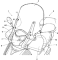
図1に示す鞍乗り型車両の風防装置(以下、風防装置)1は、鞍乗り型車両(以下、車両という)2の前頭部に設けられたスクリーン3と、該スクリーン3を取付固定するステイ4とを備え、走行時において多くの風がユーザの頭を越えるようにすることができ、ユーザの快適性を向上し得るように構成されている。車両2の前頭部には、ヘッドランプ5、メータパネル(図示しない)を備えるハンドルカバー6、前記ハンドルカバー6から突出したバーハンドル7、該バーハンドル7の両端の前方を覆うナックルガード8、前記バーハンドル7に固定したサイドミラー9が設けられており、前記ハンドルカバー6の上方に前記スクリーン3が配置される。 A windshield device (hereinafter referred to as a windshield device) 1 for a saddle-ride type vehicle shown in FIG. 1 is provided with a screen 3 provided at the front of a saddle-ride type vehicle (hereinafter referred to as a vehicle) 2 and the screen 3 is attached and fixed. The stay 4 is provided so that a large amount of wind can exceed the user's head when traveling, and the comfort of the user can be improved. On the front head of the vehicle 2, a head lamp 5, a handle cover 6 having a meter panel (not shown), a bar handle 7 protruding from the handle cover 6, a knuckle guard 8 covering the front of both ends of the bar handle 7, A side mirror 9 fixed to the bar handle 7 is provided, and the screen 3 is disposed above the handle cover 6.

このように構成された前記車両2の前頭部において、スクリーン3は、ハンドルカバー6の前面にヘッドランプ5を挟んで左右に配置された一対のステイ4により、前面側から支持されている。ステイ4をハンドルカバー6の前面に配置し、スクリーン3の前面側から支持することとしたことにより、前頭部のシート10側のスペースが狭くなることがないので、ユーザに解放感を与えることができる。尚、ステイ4は、ハンドルカバー6との間に隙間を形成して、取り付けられる。 In the front head of the vehicle 2 configured as described above, the screen 3 is supported from the front side by a pair of stays 4 arranged on the left and right with the headlamp 5 sandwiched between the front surface of the handle cover 6. By arranging the stay 4 on the front surface of the handle cover 6 and supporting it from the front surface side of the screen 3, the space on the front 10 side of the seat 10 is not reduced, so that the user feels free. Can do. The stay 4 is attached with a gap formed between the stay 4 and the handle cover 6.

また、スクリーン3は、樹脂材料で形成された透明の板部材からなり、鞍形状に成形され、左右対称形状を有している。このスクリーン3とステイ4とは、グロメット11を介して固定することにより、スクリーン3とステイ4との間に隙間A1が形成される。これにより、スクリーン3に当接した空気が、前記隙間A1から通り抜けることができる。また、スクリーン3は、ハンドルカバー6の上面との間にも隙間A2を形成し得るように設置される。また、グロメット11は弾性体を用いることができ、例えば、弾性を有するゴム材料からなるゴムダンパーとしてもよい。 The screen 3 is made of a transparent plate member made of a resin material, is formed into a bowl shape, and has a bilaterally symmetric shape. The screen 3 and the stay 4 are fixed via a grommet 11 so that a gap A1 is formed between the screen 3 and the stay 4. Thereby, the air which contact | abutted to the screen 3 can pass through said clearance gap A1. Further, the screen 3 is installed so as to form a gap A2 between the upper surface of the handle cover 6 and the screen 3. Further, the grommet 11 can use an elastic body, for example, a rubber damper made of a rubber material having elasticity.

図2に示すように、ステイ4は、樹脂材料で形成された略鉛直方向に延びる一端と略水平方向に延びる他端とからなるL字形部材で構成され、一端側に前記スクリーン3の前面側から前記スクリーン3を支持する支持部15を有する。支持部15は、スクリーン3の下端から上方に向かって延び、スクリーン3にボルト止めされる。また、ステイ4は、前記一端側に対し後方へ延びる他端側に前記車両2に固定する固定部16を備える。固定部16は、支持部15の下端から後方に向かって延びる部材で構成され、バーハンドル7にボルトで固定される。また、支持部15と固定部16との接続部分は、湾曲状であって、支持部15と固定部16とは、一体的に形成される。 As shown in FIG. 2, the stay 4 is composed of an L-shaped member formed of a resin material and having one end extending in a substantially vertical direction and the other end extending in a substantially horizontal direction. To a support portion 15 for supporting the screen 3. The support portion 15 extends upward from the lower end of the screen 3 and is bolted to the screen 3. The stay 4 includes a fixing portion 16 that is fixed to the vehicle 2 on the other end side that extends rearward with respect to the one end side. The fixing portion 16 is configured by a member extending rearward from the lower end of the support portion 15 and is fixed to the bar handle 7 with a bolt. The connecting portion between the support portion 15 and the fixing portion 16 is curved, and the support portion 15 and the fixing portion 16 are integrally formed.

このステイ4は、樹脂材料で形成されていることにより、断面形状を円形状、非円形状など自由に選定することができる、本実施形態では、整流効果を向上するため、非円形、例えば矩形状とすることが好ましい。また、ステイ4の表面側、すなわち車両2に設置された場合の前面側は、美感を与え得る表面処理が施されるのが好ましい。一方、ステイ4の裏面側、すなわち車両2に設置された場合の後面側は、突条22が複数、縦横に形成されており、これにより、ステイ4の強度を向上することができる。 Since the stay 4 is formed of a resin material, the cross-sectional shape can be freely selected, such as a circular shape or a non-circular shape. In this embodiment, a non-circular shape such as a rectangular shape is used to improve the rectification effect. A shape is preferable. In addition, it is preferable that the surface side of the stay 4, that is, the front side when installed on the vehicle 2, be subjected to a surface treatment that can give aesthetics. On the other hand, the back surface side of the stay 4, that is, the rear surface side when installed in the vehicle 2, is formed with a plurality of ridges 22 in the vertical and horizontal directions, whereby the strength of the stay 4 can be improved.

ナックルガード8は、バーハンドル7を握るユーザの手を覆うように、スクリーン3と別体として設けられており、ステイ4の固定部16近傍に固定されると共に、上端においてスクリーン3に連結されている。このナックルガード8は、上端においてスクリーン3と連結するためのボルトBを挿通する穴を穿設した当接部分17と、前記当接部分17より下方に形成されたミラー取付用ステイ18との連結用穴19と、下端においてステイ4と固定するための固定穴20とが設けられている。 The knuckle guard 8 is provided separately from the screen 3 so as to cover the user's hand holding the bar handle 7, and is fixed to the vicinity of the fixing portion 16 of the stay 4 and is connected to the screen 3 at the upper end. Yes. The knuckle guard 8 is connected to a contact portion 17 having a hole through which a bolt B for connection to the screen 3 is inserted at the upper end and a mirror mounting stay 18 formed below the contact portion 17. A working hole 19 and a fixing hole 20 for fixing to the stay 4 at the lower end are provided.

また、ミラー取付用ステイ18は、中央にサイドミラー9の雄ネジが挿通する支持穴21が設けられており、ステイ4の略中央とナックルガード8との間に橋架され、ステイ4及びナックルガード8に固定される。 Further, the mirror mounting stay 18 is provided with a support hole 21 through which the male thread of the side mirror 9 is inserted in the center, and is bridged between the approximate center of the stay 4 and the knuckle guard 8, and the stay 4 and the knuckle guard. 8 is fixed.

図3に示すように、バーハンドル7は、中央において車体前端に一体に設けられたヘッドパイプに軸支される軸25の上端に接続されてなり、両端にグリップ部26を備える。このバーハンドル7と軸25との接続部分の近傍に、ステイ4の他端に形成された固定部16を固定する取付部27が、軸25を挟んで左右に一対設けられている。取付部27は、バーハンドル7に溶接により固定される支持杆28と、該支持杆28に溶接により固定されたブラケット29とからなる。支持杆28はL字形に形成され、一端が前方に突出するように、他端をバーハンドル7の下方に固定する。そして、このバーハンドル7の下方に固定された支持杆28の外側面には、ブラケット29が固定されている。前記ブラケット29は、両端を直角に立上形成した枠部30と、該枠部30に挟まれた平坦部31とからなり、平坦部31には、ステイ4の他端を固定するボルトBを挿通するための穴(図示しない)が穿設され、該穴を塞ぐようにボルトBが螺合するナットNが予め固定されている。 As shown in FIG. 3, the bar handle 7 is connected to the upper end of a shaft 25 that is pivotally supported by a head pipe integrally provided at the front end of the vehicle body at the center, and includes grip portions 26 at both ends. In the vicinity of the connecting portion between the bar handle 7 and the shaft 25, a pair of mounting portions 27 for fixing the fixing portion 16 formed at the other end of the stay 4 are provided on the left and right sides with the shaft 25 interposed therebetween. The attachment portion 27 includes a support rod 28 fixed to the bar handle 7 by welding and a bracket 29 fixed to the support rod 28 by welding. The support rod 28 is formed in an L shape, and the other end is fixed below the bar handle 7 so that one end protrudes forward. A bracket 29 is fixed to the outer surface of the support rod 28 fixed below the bar handle 7. The bracket 29 is composed of a frame portion 30 formed with both ends rising at right angles, and a flat portion 31 sandwiched between the frame portions 30, and a bolt B for fixing the other end of the stay 4 is attached to the flat portion 31. A hole (not shown) for insertion is drilled, and a nut N into which the bolt B is screwed so as to close the hole is fixed in advance.

図4に示すように、スクリーン3は、平面視において前方Fへ向かって凸となる湾曲形状を有している。また、ステイ4は、平面視において前方Fへ凸となるリブ35を備えている。このリブ35は、支持部15のほぼ全長に亘って形成されている。スクリーン3の表面は、高さ方向の略中央において、前方Fへの突出高さがステイ4のリブ35高さよりH1だけ低くなるように形成されている。 As shown in FIG. 4, the screen 3 has a curved shape that is convex toward the front F in plan view. The stay 4 includes a rib 35 that protrudes forward F in plan view. The rib 35 is formed over substantially the entire length of the support portion 15. The surface of the screen 3 is formed so that the protruding height toward the front F is lower than the height of the rib 35 of the stay 4 by H1 at substantially the center in the height direction.

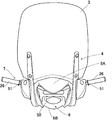
図5に示すように、ステイ4は、前記支持部15が、左右方向における前記スクリーン3の中心Iと外縁との中間に配置され、支持部15に設けたボルト挿通穴40に取り付けボルトBを挿通しスクリーン3と固定する。正面視において、支持部15は、垂線Iに対し角度αを有し、上方へいくに従ってV字状に外側へ傾くように固定される。これにより、支持部15は、スクリーン3の幅方向の外縁からスクリーン3の幅の1/4の長さの範囲に配置される。このように構成したことにより、ステイ4は、支持部15に設けたボルト挿通穴40を、スクリーン3の幅方向の外縁からスクリーン3の幅の1/4の長さの範囲に配置することができる。これにより、スクリーン3前面に整流効果が強く得られ、スクリーン3後方への空気の流れが上方に押上げられるのでユーザのウィンドシールド効果を高めることができる。本実施の形態では、スクリーン3の中心Iから支持部15までの長さL1より、支持部15からスクリーン3の外縁までの長さL2の方が短くなるように形成されている。 As shown in FIG. 5, in the stay 4, the support portion 15 is disposed in the middle between the center I and the outer edge of the screen 3 in the left-right direction, and the mounting bolt B is installed in the bolt insertion hole 40 provided in the support portion 15. Fix with the insertion screen 3. When viewed from the front, the support portion 15 has an angle α with respect to the perpendicular I, and is fixed so as to be inclined outward in a V shape as it goes upward. As a result, the support portion 15 is disposed in a range of ¼ of the width of the screen 3 from the outer edge in the width direction of the screen 3. With this configuration, the stay 4 can arrange the bolt insertion hole 40 provided in the support portion 15 within a range of a quarter length of the width of the screen 3 from the outer edge in the width direction of the screen 3. it can. As a result, a strong rectification effect is obtained on the front surface of the screen 3, and the air flow toward the rear of the screen 3 is pushed upward, so that the user's windshield effect can be enhanced. In the present embodiment, the length L2 from the support 15 to the outer edge of the screen 3 is shorter than the length L1 from the center I of the screen 3 to the support 15.

また、ステイ4は、支持部15の上端の位置がスクリーン3の高さの半分以下となる長さに形成される。すなわち、ステイ4は、スクリーン3の下端から支持部15上端までの長さH2が、支持部15上端からスクリーン3の上端までの長さH3より短くなるように形成される。このように構成したことにより、図6に示すように、ステイ4がユーザの視界Sに入ることが少ないので、ユーザに解放感を与えることができる。このように、風防装置1では、ユーザの目線をステイ4の上端より上にあるようにすることができる。 The stay 4 is formed in such a length that the position of the upper end of the support portion 15 is not more than half the height of the screen 3. That is, the stay 4 is formed such that the length H2 from the lower end of the screen 3 to the upper end of the support portion 15 is shorter than the length H3 from the upper end of the support portion 15 to the upper end of the screen 3. With this configuration, as shown in FIG. 6, the stay 4 is less likely to enter the user's field of view S, so that the user can feel free. As described above, in the windshield device 1, the user's eyes can be located above the upper end of the stay 4.

また、スクリーン3は、側面視における幅Dが、車両2の前輪45の中心軸と、軸25との距離で表されるフロントフォーク幅Tと交差するように設置される。すなわち、スクリーン3は、上端が、後方へ傾いて軸25より車両2後方へ突出し、下端が、フロントフォーク幅T内に配置される。このようにスクリーン3を配置することにより、スクリーン3の重心をバーハンドル7の回転中心、すなわち軸25に近づけることができる。 Further, the screen 3 is installed so that the width D in a side view intersects the front fork width T expressed by the distance between the central axis of the front wheel 45 of the vehicle 2 and the shaft 25. In other words, the upper end of the screen 3 is inclined rearward and protrudes rearward of the vehicle 2 from the shaft 25, and the lower end is disposed within the front fork width T. By arranging the screen 3 in this way, the center of gravity of the screen 3 can be brought close to the rotation center of the bar handle 7, that is, the shaft 25.

図7に示すように、ハンドルカバー6は、正面にヘッドランプ用開口50が形成されており、左右両側にバーハンドル7のグリップ部26が突出するバーハンドル用開口51が形成されている。また、図8に示すようにハンドルカバー6の後面には、中央にメータパネル用開口52が形成され、バーハンドル用開口51の周囲にスイッチ用開口53が設けられている。前記メータパネル用開口52の前方側には、表面を隆起させて形成したバイザー54が設けられている。このハンドルカバー6は、冂字状に形成された上カバー6A、上カバー6Aの下部開口を塞ぐように形成された下カバー6Bとにより構成され、接続手段、例えば、ビス、爪による嵌合などにより一体化される。ハンドルカバー6は、軸25を中心として車両2の前頭部に、前記ステイ4と共に取付部27に固定される。これにより、ステイ4をバーハンドル7に固定する取付部27は、ハンドルカバー6により外部から視認できないように構成される。 As shown in FIG. 7, the handle cover 6 has a headlamp opening 50 formed in the front, and bar handle openings 51 from which the grip portion 26 of the bar handle 7 protrudes on both the left and right sides. Further, as shown in FIG. 8, a meter panel opening 52 is formed at the center of the rear surface of the handle cover 6, and a switch opening 53 is provided around the bar handle opening 51. A visor 54 formed by raising the surface is provided on the front side of the meter panel opening 52. The handle cover 6 includes an upper cover 6A formed in a square shape and a lower cover 6B formed so as to close a lower opening of the upper cover 6A. Are integrated. The handle cover 6 is fixed to the attachment portion 27 together with the stay 4 on the front head of the vehicle 2 around the shaft 25. Accordingly, the attachment portion 27 for fixing the stay 4 to the bar handle 7 is configured so that it cannot be visually recognized from the outside by the handle cover 6.

次に、上記のように構成した風防装置1の取り付け方法について図9〜図14を参照して説明する。尚、風防装置1は、略左右対称であるので、説明の便宜上、車両2の進行方向に対し左側を図示して説明を行い、右側については説明を省略する。 Next, the attachment method of the windshield apparatus 1 comprised as mentioned above is demonstrated with reference to FIGS. Since the windshield device 1 is substantially bilaterally symmetric, for the sake of convenience of explanation, the left side of the traveling direction of the vehicle 2 is illustrated and described, and the description of the right side is omitted.

まず、ヘッドランプ5、ハンドルカバー6、バーハンドル7、メータパネルが設置された車両2の前頭部に、サイドミラー9を取り付ける。サイドミラー9は、バーハンドル7に立設された雌ネジ部55にワッシャW、ミラー取付用ステイ18、カラーCの順に挿入し、サイドミラー9に形成された雄ネジ56を雌ネジ部に螺合して、バーハンドル7に取り付ける。 First, the side mirror 9 is attached to the front of the vehicle 2 on which the headlamp 5, the handle cover 6, the bar handle 7, and the meter panel are installed. The side mirror 9 is inserted in the order of the washer W, the mirror mounting stay 18 and the collar C into the female screw portion 55 erected on the bar handle 7, and the male screw 56 formed on the side mirror 9 is screwed into the female screw portion. And attach to the bar handle 7.

次いで、ステイ4をバーハンドル7及びミラー取付用ステイ18に固定する(図10)。ステイ4は、バーハンドル7に設けられた取付部27に対し、カラーC、ステイ4の固定部16、フランジカラーFCの順に配置し、フランジカラーFC側からボルトBを挿入して、取付部27のフランジ31に設けたナットNに螺合させて、ハンドルカバー6と共にバーハンドル7に固定する。このとき、ステイ4は、固定部16以外の部分では、ハンドルカバー6と隙間を形成して取り付けられる。 Next, the stay 4 is fixed to the bar handle 7 and the mirror mounting stay 18 (FIG. 10). The stay 4 is arranged in the order of the collar C, the fixing portion 16 of the stay 4 and the flange collar FC with respect to the attachment portion 27 provided on the bar handle 7, and the bolt B is inserted from the flange collar FC side to attach the attachment portion 27. The nut 31 provided on the flange 31 is screwed into the bar handle 7 together with the handle cover 6. At this time, the stay 4 is attached at a portion other than the fixing portion 16 so as to form a gap with the handle cover 6.

また、ステイ4は、サイドミラー9と共にバーハンドル7に取り付けたミラー取付用ステイ18の内側にカラーCを挟んで重ね、ミラー取付用ステイ18側からボルトBを挿入し、ステイ4側においてボルトBをナットNと螺合させて、ミラー取付用ステイ18に固定する。 Further, the stay 4 is overlapped with the side mirror 9 inside the mirror mounting stay 18 attached to the bar handle 7 with the collar C interposed therebetween, and the bolt B is inserted from the mirror mounting stay 18 side. Is screwed to the nut N and fixed to the mirror mounting stay 18.

続いて、スクリーン3の取り付け方法について、図11からの図を参照して説明する。まず、図11に示すように、スクリーン3には、ステイ4の支持部15のボルト挿通穴40に対応して設けられたボルト穴60に、予めグロメット11をそれぞれ取り付けておく。 Next, a method for attaching the screen 3 will be described with reference to the drawings from FIG. First, as shown in FIG. 11, the grommet 11 is previously attached to the screen 3 in the bolt holes 60 provided corresponding to the bolt insertion holes 40 of the support portion 15 of the stay 4.

次いで、スクリーン3の両側下部にナックルガード8を取り付ける。ナックルガード8は、図12に示すように、上端に設けられた当接部分17に形成したナット用穴61に、組付けナット62を挿入する。次いで、図13に示すように、スクリーン3の後面側からナックルガード8の当接部分17をスクリーン3に当接させ、スクリーン3の前面側からワッシャWを介して、ボルトBを挿入して、ナックルガード8の当接部分17に設けた組付けナット62に螺合することにより取り付ける。 Next, knuckle guards 8 are attached to the lower portions of both sides of the screen 3. As shown in FIG. 12, the knuckle guard 8 inserts an assembly nut 62 into a nut hole 61 formed in the contact portion 17 provided at the upper end. Next, as shown in FIG. 13, the abutting portion 17 of the knuckle guard 8 is brought into contact with the screen 3 from the rear surface side of the screen 3, and the bolt B is inserted from the front side of the screen 3 through the washer W. The knuckle guard 8 is attached by being screwed to an assembly nut 62 provided at the contact portion 17 of the knuckle guard 8.

そして、スクリーン3は、上記のようにナックルガード8を取り付けた状態で、車両2の前頭部に取り付ける。まず、スクリーン3は、バーハンドル7に取り付けたステイ4の支持部15に対し車両2の後方側に配置し、支持部15との間にカラーC、ワッシャWを挟んで、支持部15側からボルトBを挿入し、スクリーン3の後面側において、ボルトBの先端にワッシャWを挿入しナットNを螺合させて固定する。また、ナックルガード8は、下端においてステイ4の固定部16に上側から重なり、下方からカラーCを介してボルトBを挿通し、ナックルガード8側からボルトBの先端にワッシャWを挿入して、ナットNを螺合することによりステイ4に固定する。さらに、ナックルガード8は連結用穴19においてミラー用取付ステイ18に上側からカラーCを挟んで重なり、上側からボルトBを挿通し、ミラー用取付ステイ18側からボルトBの先端にワッシャWを挿入して、ナットNを螺合することにより、ミラー用取付ステイ18に固定する。以上のようにして、風防装置1では、スクリーン3をハンドルカバー6の上方に設置することができる。尚、ステイ4は、支持部15と固定部16との接続部分としての屈曲部4aにおいて、裏面に突状が形成せずに変形しやすい構成とした。これにより、ステイ4に過大な荷重が生じた場合、屈曲部が曲げ変形することにより荷重を吸収することができる。 The screen 3 is attached to the forehead of the vehicle 2 with the knuckle guard 8 attached as described above. First, the screen 3 is disposed on the rear side of the vehicle 2 with respect to the support portion 15 of the stay 4 attached to the bar handle 7, and the collar C and washer W are sandwiched between the support portion 15 and the support portion 15 side. The bolt B is inserted, and on the rear surface side of the screen 3, a washer W is inserted at the tip of the bolt B and a nut N is screwed and fixed. The knuckle guard 8 is overlapped with the fixing portion 16 of the stay 4 at the lower end from above, the bolt B is inserted through the collar C from below, and the washer W is inserted into the tip of the bolt B from the knuckle guard 8 side. The nut N is fixed to the stay 4 by screwing. Further, the knuckle guard 8 overlaps the mirror mounting stay 18 with the collar C sandwiched from the upper side in the connecting hole 19, the bolt B is inserted from the upper side, and the washer W is inserted from the mirror mounting stay 18 side to the tip of the bolt B. Then, the nut N is fixed to the mirror mounting stay 18 by screwing. As described above, in the windshield device 1, the screen 3 can be installed above the handle cover 6. It should be noted that the stay 4 is configured to be easily deformed without forming a protrusion on the back surface in the bent portion 4a as a connecting portion between the support portion 15 and the fixing portion 16. Thereby, when an excessive load is generated in the stay 4, the load can be absorbed by bending deformation of the bent portion.

次に、上記のように構成した風防装置1の作用について説明する。本実施形態に係る風防装置1は、スクリーン3をヘッドランプ5とメータパネルとを備えたハンドルカバー6の上方に配置し、該スクリーン3を前面側からステイ4により支持することとした。従って、スクリーン3の後面側、すなわちシート10に着座したユーザ側にステイ4が突出することがない。これにより、風防装置1では、スクリーン3の後面側のスペースを広くすることができ、ユーザに解放感を与えることができる。また、スクリーン3の後面側に凸となるステイ4がないので、スクリーン3の後面側が解放的になり、バーハンドル7とスクリーン3との間に配置される機器との干渉が少なくできて取付位置の自由度が増し、さらに停車時に、そこに簡易的に物を置くスペースを広く取ることができる。 Next, the operation of the windshield device 1 configured as described above will be described. In the windshield device 1 according to the present embodiment, the screen 3 is disposed above the handle cover 6 including the headlamp 5 and the meter panel, and the screen 3 is supported by the stay 4 from the front side. Therefore, the stay 4 does not protrude on the rear surface side of the screen 3, that is, on the user side seated on the seat 10. Thereby, in the windshield device 1, the space on the rear surface side of the screen 3 can be widened, and a feeling of release can be given to the user. In addition, since there is no convex stay 4 on the rear surface side of the screen 3, the rear surface side of the screen 3 becomes releasable, and interference with equipment arranged between the bar handle 7 and the screen 3 can be reduced and the mounting position can be reduced. The degree of freedom is increased, and when the vehicle stops, a large space can be easily placed there.

ステイ4は、支持部15において、弾性部材たるグロメット11を介してスクリーン3を支持することにより、支持部15とスクリーン3との間に隙間A1を形成した。これにより、風防装置1では、スクリーン3で受けた空気の一部を円滑にスクリーン3の左右方向へ逃すことができる。また、グロメット11は、弾性を有するゴム材料からなるゴムダンパーとすることにより、エンジン振動の多いV型エンジンを持つ車両の場合でも、ステイ4とウィンドシールドとがゴムダンパーを介して接触することとしたので、ノイズの発生を抑制することができる。 In the stay 4, the support portion 15 supports the screen 3 via the grommet 11 as an elastic member, thereby forming a gap A 1 between the support portion 15 and the screen 3. Thereby, in the windshield device 1, a part of the air received by the screen 3 can be smoothly released to the left and right directions of the screen 3. Further, the grommet 11 is a rubber damper made of a rubber material having elasticity, so that the stay 4 and the windshield come into contact with each other through the rubber damper even in a vehicle having a V-type engine with a lot of engine vibration. Therefore, the generation of noise can be suppressed.

さらに、ステイ4は、ハンドルカバー6の上面とスクリーン3の下端との間に隙間A2を形成してスクリーン3を支持するように構成した。これにより車両2の走行時において、スクリーン3前面で受けた空気をハンドルカバー6の上面とスクリーン3の下端との間の隙間A2から逃すことができる。これにより、風防装置1では、スクリーン3前後における圧力差を小さくすることができる。 Furthermore, the stay 4 is configured to support the screen 3 by forming a gap A2 between the upper surface of the handle cover 6 and the lower end of the screen 3. Thereby, when the vehicle 2 is traveling, the air received on the front surface of the screen 3 can be released from the gap A2 between the upper surface of the handle cover 6 and the lower end of the screen 3. Thereby, in the windshield device 1, the pressure difference before and behind the screen 3 can be made small.

また、ステイ4は、支持部15のほぼ全長に亘って前方へ凸となるリブ35を形成し、スクリーン3で受けた空気をリブ35に沿ってスクリーン3の上方へ押上げることができる。また、ステイ4は支持部15が上方へいくに従ってV字状に外側へ傾くように固定される。これにより、風防装置1はスクリーン3で受けた空気の多くを車両2の上方へ逃すことにより、多くの風がユーザの頭を越えるようにすることができ、快適性を向上することができる。 Further, the stay 4 forms a rib 35 that protrudes forward substantially over the entire length of the support portion 15, and the air received by the screen 3 can be pushed up above the screen 3 along the rib 35. The stay 4 is fixed so as to be inclined outward in a V shape as the support portion 15 is moved upward. As a result, the windshield device 1 allows most of the air received by the screen 3 to escape above the vehicle 2, so that a lot of wind can pass over the user's head, and comfort can be improved.

また、ステイ4は、支持部15の上端の位置がスクリーン3の高さの半分以下となるように形成される。従って、風防装置1では、スクリーン3の前面側にステイ4を配置しているが、支持部15がユーザの視界に入ることが少ないので、ユーザに解放感を与え、快適性を向上することができる。さらに、スクリーン3の前面に、上方への空気の流れが強く得られ、スクリーン3の後方への空気の流れが上方に押上げられるので、ユーザのウィンドシールド効果を高めることができる。 The stay 4 is formed so that the position of the upper end of the support portion 15 is not more than half the height of the screen 3. Therefore, in the windshield device 1, the stay 4 is arranged on the front side of the screen 3, but the support portion 15 rarely enters the user's field of view, which gives the user a feeling of release and improves comfort. it can. Further, a strong air flow is obtained on the front surface of the screen 3 and the air flow behind the screen 3 is pushed upward, so that the user's windshield effect can be enhanced.

また、スクリーン3は、スクリーン3の上端が、後方へ傾いて軸25より車両2の後方へ突出し、スクリーン3の下端が、フロントフォーク幅T内に配置される。これにより、スクリーン3の重心をバーハンドル7の回転中心(軸25)に近づけることができる。また、スクリーン3は、上端を後方へ傾けて設置したことにより、スクリーン3で受けた空気を車両2の上方へ逃すことができ、多くの風がユーザの頭を越えるようにすることができ、快適性を向上することができる。 Further, the screen 3 has the upper end of the screen 3 tilted rearward and protrudes rearward of the vehicle 2 from the shaft 25, and the lower end of the screen 3 is disposed within the front fork width T. As a result, the center of gravity of the screen 3 can be brought closer to the rotation center (axis 25) of the bar handle 7. In addition, the screen 3 is installed with its upper end tilted rearward, so that the air received by the screen 3 can escape to the upper side of the vehicle 2 so that many winds can pass over the user's head. Comfort can be improved.

また、ステイ4は樹脂材料により形成される。これにより、従来のようにパイプ状とする必要がなく、断面を非円形状すなわち板形状とすることができ、デザイン性を向上することができる。さらに、ステイ4は、所定方向の荷重に対し、容易に変形し得る形状とすることにより、衝撃を吸収することができる。 The stay 4 is made of a resin material. Thereby, it is not necessary to use a pipe shape as in the prior art, and the cross section can be made into a non-circular shape, that is, a plate shape, and the design can be improved. Furthermore, the stay 4 can absorb an impact by having a shape that can be easily deformed with respect to a load in a predetermined direction.

また、サイドミラー9は、ステイ4とは別体のミラー取付用ステイ18に保持されている。そして、ミラー取付用ステイ18は、ステイ4に過大な荷重がはたらいた場合にステイ4との結合が解除され得るように構成した。これにより、ミラー取付用ステイ18は、過大な荷重を受けたステイ4が変形した場合でも、ステイ4との結合を解除し、サイドミラー9が損傷を受けるのを防止することができる。また、ステイ4は、屈曲部4aにおいて変形しやすい構成としたので、ステイ4に荷重が生じた場合、屈曲部4aが曲げ変形することにより荷重を吸収することができる。 The side mirror 9 is held by a mirror mounting stay 18 that is separate from the stay 4. The stay 18 for attaching the mirror is configured so that the connection with the stay 4 can be released when an excessive load is applied to the stay 4. Thereby, the stay 18 for attaching the mirror can release the coupling with the stay 4 and prevent the side mirror 9 from being damaged even when the stay 4 receiving an excessive load is deformed. Further, since the stay 4 is configured to be easily deformed in the bent portion 4a, when a load is generated in the stay 4, the bent portion 4a is bent and deformed so that the load can be absorbed.

また、ステイ4の他端を固定する取付部27は、バーハンドル7の軸25との接続部分の近傍に、左右一対設けたことにより、バーハンドル7の回転中心にステイ4に取り付けたスクリーン3の重心を近づけることができる。 In addition, a pair of left and right mounting portions 27 for fixing the other end of the stay 4 are provided in the vicinity of the connection portion of the bar handle 7 with the shaft 25, so that the screen 3 attached to the stay 4 at the center of rotation of the bar handle 7. The center of gravity can be brought closer.

本発明は、本実施形態に限定されるものではなく、本発明の要旨の範囲内で種々の変形実施が可能である。例えば、本実施形態では、ステイは左右一対からなるものについて説明したが、本発明はこれに限らず、例えば、一対のステイの支持部の間に支持部を連結する横架部材を備えることとし、左右一対のステイを一体化することとしてもよい。 The present invention is not limited to this embodiment, and various modifications can be made within the scope of the gist of the present invention. For example, in this embodiment, the stay has been described as consisting of a pair of left and right. However, the present invention is not limited to this, and for example, a horizontal member that connects the support portions between the support portions of the pair of stays is provided. The pair of left and right stays may be integrated.

本発明の風防装置の全体構成を示す斜視図である。It is a perspective view showing the whole windshield device composition of the present invention. 同上、スクリーンの支持構造を示す斜視図であり、(a)正面側から見た図、(b)背面側から見た図である。It is a perspective view which shows the support structure of a screen same as the above, (a) The figure seen from the front side, (b) The figure seen from the back side. 同上、バーハンドルの構成を示す斜視図である。It is a perspective view which shows the structure of a bar handle same as the above. 同上、ステイに保持したスクリーンの断面図である。It is sectional drawing of the screen hold | maintained to the stay same as the above. 同上、スクリーンとバーハンドルとの位置関係を示す分解した状態の正面図である。It is a front view of the exploded state which shows the positional relationship of a screen and a bar handle same as the above. 同上、車両の側面図である。It is a side view of a vehicle same as the above. 同上、ハンドルカバーの正面図である。It is a front view of a handle cover same as the above. 同上、ハンドルカバーの背面図である。It is a rear view of a handle cover same as the above. 同上、風防装置の取り付け状態を示す斜視図である。It is a perspective view which shows the attachment state of a windshield apparatus same as the above. 同上、風防装置の取り付け状態を示す斜視図である。It is a perspective view which shows the attachment state of a windshield apparatus same as the above. 同上、風防装置の取り付け状態を示す斜視図である。It is a perspective view which shows the attachment state of a windshield apparatus same as the above. 同上、風防装置の取り付け状態を示す斜視図である。It is a perspective view which shows the attachment state of a windshield apparatus same as the above. 同上、風防装置の取り付け状態を示す斜視図である。It is a perspective view which shows the attachment state of a windshield apparatus same as the above. 同上、風防装置の取り付け状態を示す斜視図である。It is a perspective view which shows the attachment state of a windshield apparatus same as the above.

符号の説明Explanation of symbols

1 風防装置
2 車両(鞍乗り型車両)
3 スクリーン
4 ステイ
7 バーハンドル
11 グロメット(弾性部材)
15 支持部
16 固定部
A1 隙間
1 Windshield device 2 Vehicle (saddle-ride type vehicle)
3 Screen 4 Stay 7 Bar handle
11 Grommet (elastic member)
15 Support part
16 Fixed part
A1 Clearance

Claims (5)

鞍乗り型車両の前頭部に取付ける鞍乗り型車両の風防装置において、
スクリーンと、前記スクリーンを支持するステイとを備え、
前記ステイは、
一端側に前記スクリーンの前面側から前記スクリーンを支持する支持部を有し、
前記一端側に対し下方へ延びる他端側に前記鞍乗り型車両に固定する固定部を備え、
前記支持部と前記スクリーンとの間に隙間を形成し、
前記支持部の上端は前記スクリーンの上端より下方となる高さに形成される
ことを特徴とする鞍乗り型車両の風防装置。
In a windshield device for a saddle type vehicle that is attached to the front of the saddle type vehicle,
A screen and a stay for supporting the screen;
The stay
A support portion for supporting the screen from the front side of the screen on one end side;
A fixing portion for fixing to the saddle riding type vehicle on the other end side extending downward with respect to the one end side;
Forming a gap between the support and the screen;
The windshield device for a saddle-ride type vehicle, wherein an upper end of the support portion is formed at a height below the upper end of the screen .
前記ステイは、左右一対設けられ、
前記支持部が、左右方向における前記スクリーンの中心と外縁との間に配置され、
前記固定部が、バーハンドルの下方に固定されることを特徴とする請求項1記載の鞍乗り型車両の風防装置。
The stay is provided in a pair of left and right,
The support portion is disposed between a center and an outer edge of the screen in the left-right direction;
The windshield device for a saddle-ride type vehicle according to claim 1, wherein the fixing portion is fixed below the bar handle.
前記支持部と前記スクリーンとの間に弾性部材を設けたことを特徴とする請求項1又は2記載の鞍乗り型車両の風防装置。 The windshield device for a saddle-ride type vehicle according to claim 1 or 2, wherein an elastic member is provided between the support portion and the screen. 前記ステイは断面形状が非円形であり、正面視において垂線に対し所定角度を有し上方へいくに従って外側へ傾くように固定される
ことを特徴とする請求項1〜3のいずれか1項に記載の鞍乗り型車両の風防装置。
The stay has a non-circular cross-sectional shape, and is fixed so as to incline outward as it goes upward with a predetermined angle with respect to a perpendicular line when viewed from the front. A windshield device for a saddle-ride type vehicle according to claim 1.
前記固定部は、前記支持部の下端から後方へ延びる部材で構成したことを特徴とする請求項1〜4のいずれか1項に記載の鞍乗り型車両の風防装置。
The windshield device for a saddle-ride type vehicle according to any one of claims 1 to 4, wherein the fixing portion is configured by a member extending rearward from a lower end of the support portion.
JP2006275693A 2006-10-06 2006-10-06 Windshield device for saddle-ride type vehicles Expired - Fee Related JP4332899B2 (en)

Priority Applications (2)

Application Number Priority Date Filing Date Title
JP2006275693A JP4332899B2 (en) 2006-10-06 2006-10-06 Windshield device for saddle-ride type vehicles
EP07019543.3A EP1908676B1 (en) 2006-10-06 2007-10-05 Windshield apparatus for saddle-type vehicle

Applications Claiming Priority (1)

Application Number Priority Date Filing Date Title
JP2006275693A JP4332899B2 (en) 2006-10-06 2006-10-06 Windshield device for saddle-ride type vehicles

Publications (2)

Publication Number Publication Date
JP2008094169A JP2008094169A (en) 2008-04-24
JP4332899B2 true JP4332899B2 (en) 2009-09-16

Family

ID=38870248

Family Applications (1)

Application Number Title Priority Date Filing Date
JP2006275693A Expired - Fee Related JP4332899B2 (en) 2006-10-06 2006-10-06 Windshield device for saddle-ride type vehicles

Country Status (2)

Country Link
EP (1) EP1908676B1 (en)
JP (1) JP4332899B2 (en)

Families Citing this family (5)

* Cited by examiner, † Cited by third party
Publication number Priority date Publication date Assignee Title
IT1395380B1 (en) * 2009-09-07 2012-09-14 Piaggio & C Spa FIXING DEVICE FOR ACCESSORIES IN A MOTORCYCLE, IN PARTICULAR FOR WINDSCREENS
JP5634195B2 (en) * 2010-09-29 2014-12-03 本田技研工業株式会社 Small vehicle
JP5494416B2 (en) * 2010-10-27 2014-05-14 本田技研工業株式会社 Windshield device for saddle-ride type vehicles
JP5729076B2 (en) * 2011-03-28 2015-06-03 本田技研工業株式会社 Windshield device for saddle-ride type vehicle and its mounting method
JP6935978B2 (en) * 2018-09-27 2021-09-15 本田技研工業株式会社 Saddle-type vehicle

Family Cites Families (6)

* Cited by examiner, † Cited by third party
Publication number Priority date Publication date Assignee Title
GB241692A (en) * 1924-10-03 1925-10-29 Brooks J B & Co Ltd Improvements relating to windscreens for motor-cycles
GB2263259A (en) * 1992-01-13 1993-07-21 Piaggio Veicoli Europ Windscreen connection device in a two-wheel vehicle
JP3756257B2 (en) * 1996-07-10 2006-03-15 本田技研工業株式会社 Motorcycle windshield device
US6343827B1 (en) * 2000-06-08 2002-02-05 John P. Nepper, Sr. Bridgelike connector (axially extending between apertured leadward rigid-sheet and trailward fixture-bar(s) )
US6736441B1 (en) * 2003-03-07 2004-05-18 Harley-Davidson Motor Company Group, Inc. Detachable windshield for a motorcycle
JP4520269B2 (en) * 2004-09-30 2010-08-04 本田技研工業株式会社 Light vehicle windscreen mounting structure

Also Published As

Publication number Publication date
EP1908676A2 (en) 2008-04-09
JP2008094169A (en) 2008-04-24
EP1908676A3 (en) 2010-09-22
EP1908676B1 (en) 2016-07-20

Similar Documents

Publication Publication Date Title
JP4332899B2 (en) Windshield device for saddle-ride type vehicles
JP3976197B2 (en) Front body structure of automobile
JP5460526B2 (en) Front structure of motorcycle
EP2128007A1 (en) Motorcycle
JP4676281B2 (en) Vehicle flap
JP5607016B2 (en) Guard pipe mounting structure for motorcycles
WO2009098925A1 (en) Saddle-type vehicle
US7513559B2 (en) Vehicle
JP6837791B2 (en) Front cowl of saddle-type vehicle
JP5604328B2 (en) Screen mounting structure for saddle-ride type vehicles
JP4847925B2 (en) Horn mounting structure
JP4313590B2 (en) Front fender mounting structure
JP2006069299A (en) Rear view mirror supporting structure of motorcycle
JP2010064579A (en) Side cover of motorcycle
JPH0616166A (en) Cowling device of motorcycle
JP4991463B2 (en) Vehicle windshield mounting structure
JP6773715B2 (en) Saddle-type vehicle
JP6719524B2 (en) Blinker lamp mounting structure for saddle type vehicles
JP2012201349A (en) Windshield device for saddle-ride type vehicle and mounting method thereof
JP5494416B2 (en) Windshield device for saddle-ride type vehicles
JP2005119391A (en) Front cover structure for scooter type vehicle
JP6498231B2 (en) Fork guard structure
JP3336003B2 (en) Vehicle tail lamp device
JP4073849B2 (en) Rear fender structure in motorcycles
US20230202602A1 (en) Saddled vehicle

Legal Events

Date Code Title Description
A977 Report on retrieval

Free format text: JAPANESE INTERMEDIATE CODE: A971007

Effective date: 20080903

A131 Notification of reasons for refusal

Free format text: JAPANESE INTERMEDIATE CODE: A131

Effective date: 20080908

A521 Written amendment

Free format text: JAPANESE INTERMEDIATE CODE: A523

Effective date: 20081105

TRDD Decision of grant or rejection written
A01 Written decision to grant a patent or to grant a registration (utility model)

Free format text: JAPANESE INTERMEDIATE CODE: A01

Effective date: 20090601

A01 Written decision to grant a patent or to grant a registration (utility model)

Free format text: JAPANESE INTERMEDIATE CODE: A01

A61 First payment of annual fees (during grant procedure)

Free format text: JAPANESE INTERMEDIATE CODE: A61

Effective date: 20090614

FPAY Renewal fee payment (event date is renewal date of database)

Free format text: PAYMENT UNTIL: 20120703

Year of fee payment: 3

R150 Certificate of patent or registration of utility model

Ref document number: 4332899

Country of ref document: JP

Free format text: JAPANESE INTERMEDIATE CODE: R150

Free format text: JAPANESE INTERMEDIATE CODE: R150

FPAY Renewal fee payment (event date is renewal date of database)

Free format text: PAYMENT UNTIL: 20120703

Year of fee payment: 3

S111 Request for change of ownership or part of ownership

Free format text: JAPANESE INTERMEDIATE CODE: R313113

FPAY Renewal fee payment (event date is renewal date of database)

Free format text: PAYMENT UNTIL: 20120703

Year of fee payment: 3

R350 Written notification of registration of transfer

Free format text: JAPANESE INTERMEDIATE CODE: R350

FPAY Renewal fee payment (event date is renewal date of database)

Free format text: PAYMENT UNTIL: 20120703

Year of fee payment: 3

FPAY Renewal fee payment (event date is renewal date of database)

Free format text: PAYMENT UNTIL: 20130703

Year of fee payment: 4

FPAY Renewal fee payment (event date is renewal date of database)

Free format text: PAYMENT UNTIL: 20140703

Year of fee payment: 5

LAPS Cancellation because of no payment of annual fees