EP2291920B1 - Störerreduktion - Google Patents
Störerreduktion Download PDFInfo
- Publication number
- EP2291920B1 EP2291920B1 EP08767236.6A EP08767236A EP2291920B1 EP 2291920 B1 EP2291920 B1 EP 2291920B1 EP 08767236 A EP08767236 A EP 08767236A EP 2291920 B1 EP2291920 B1 EP 2291920B1
- Authority
- EP
- European Patent Office
- Prior art keywords
- interfering signal
- channel
- signal
- band
- transmitter
- Prior art date
- Legal status (The legal status is an assumption and is not a legal conclusion. Google has not performed a legal analysis and makes no representation as to the accuracy of the status listed.)
- Active
Links
- 230000002452 interceptive effect Effects 0.000 claims description 118
- 238000000034 method Methods 0.000 claims description 41
- 230000009021 linear effect Effects 0.000 claims description 25
- 238000004364 calculation method Methods 0.000 claims description 13
- 238000005259 measurement Methods 0.000 claims description 6
- 238000001914 filtration Methods 0.000 claims 1
- 238000004891 communication Methods 0.000 description 29
- 230000001413 cellular effect Effects 0.000 description 21
- 238000005516 engineering process Methods 0.000 description 14
- 230000014509 gene expression Effects 0.000 description 13
- 238000012546 transfer Methods 0.000 description 8
- 238000001514 detection method Methods 0.000 description 4
- 230000005540 biological transmission Effects 0.000 description 3
- 230000008030 elimination Effects 0.000 description 3
- 238000003379 elimination reaction Methods 0.000 description 3
- 238000001228 spectrum Methods 0.000 description 3
- 238000004422 calculation algorithm Methods 0.000 description 2
- 230000007423 decrease Effects 0.000 description 2
- IRLPACMLTUPBCL-KQYNXXCUSA-N 5'-adenylyl sulfate Chemical compound C1=NC=2C(N)=NC=NC=2N1[C@@H]1O[C@H](COP(O)(=O)OS(O)(=O)=O)[C@@H](O)[C@H]1O IRLPACMLTUPBCL-KQYNXXCUSA-N 0.000 description 1
- 230000009286 beneficial effect Effects 0.000 description 1
- 230000010267 cellular communication Effects 0.000 description 1
- 239000002131 composite material Substances 0.000 description 1
- 230000001419 dependent effect Effects 0.000 description 1
- 238000011161 development Methods 0.000 description 1
- 230000000977 initiatory effect Effects 0.000 description 1
- 230000007774 longterm Effects 0.000 description 1
- 238000010295 mobile communication Methods 0.000 description 1
- 238000005312 nonlinear dynamic Methods 0.000 description 1
- 238000012545 processing Methods 0.000 description 1
- 230000035945 sensitivity Effects 0.000 description 1
Images


Classifications
-
- H—ELECTRICITY
- H04—ELECTRIC COMMUNICATION TECHNIQUE
- H04B—TRANSMISSION
- H04B1/00—Details of transmission systems, not covered by a single one of groups H04B3/00 - H04B13/00; Details of transmission systems not characterised by the medium used for transmission
- H04B1/06—Receivers
- H04B1/10—Means associated with receiver for limiting or suppressing noise or interference
- H04B1/12—Neutralising, balancing, or compensation arrangements
- H04B1/123—Neutralising, balancing, or compensation arrangements using adaptive balancing or compensation means
- H04B1/126—Neutralising, balancing, or compensation arrangements using adaptive balancing or compensation means having multiple inputs, e.g. auxiliary antenna for receiving interfering signal
-
- H—ELECTRICITY
- H04—ELECTRIC COMMUNICATION TECHNIQUE
- H04B—TRANSMISSION
- H04B1/00—Details of transmission systems, not covered by a single one of groups H04B3/00 - H04B13/00; Details of transmission systems not characterised by the medium used for transmission
- H04B1/06—Receivers
- H04B1/10—Means associated with receiver for limiting or suppressing noise or interference
- H04B1/109—Means associated with receiver for limiting or suppressing noise or interference by improving strong signal performance of the receiver when strong unwanted signals are present at the receiver input
-
- H—ELECTRICITY
- H04—ELECTRIC COMMUNICATION TECHNIQUE
- H04B—TRANSMISSION
- H04B1/00—Details of transmission systems, not covered by a single one of groups H04B3/00 - H04B13/00; Details of transmission systems not characterised by the medium used for transmission
- H04B1/06—Receivers
- H04B1/10—Means associated with receiver for limiting or suppressing noise or interference
- H04B1/1027—Means associated with receiver for limiting or suppressing noise or interference assessing signal quality or detecting noise/interference for the received signal
- H04B2001/1045—Adjacent-channel interference
Definitions
- the invention is related to communication between nodes in a wireless communication network. More particular, the invention is related to a reduction of an interfering signal received by a node in a wireless communication network.
- a cellular network is a radio network made up of a number of radio cells each served by a fixed transceiver, known as a cell site or base station. As is well known, the cells in a cellular network are used to cover different areas in order to provide radio coverage over a wider area than the area of one single cell.
- a common example of a cellular network is the cell phone networks, wherein signals are communicated by means of radio waves between a mobile telephone or a similar portable communication device and a cell site (base station) or a similar access point.
- GSM Global System for Mobile Communications
- GPRS General Packet Radio Service
- EDGE Enhanced Data rates for GSM Evolution
- UMTS Universal Mobile Telecommunications System
- 3GPP Third Generation Partnership Project
- 3GPP LTE Long Term Evolution
- CDMA Code Division Multiple Access
- EV-DO Evolution-Data Optimized
- WiMAX Worldwide Interoperability for Microwave Access
- DECT Digital Enhanced Cordless Telecommunications
- iDEN Integrated Digital Enhanced Network
- the invention described herein is applicable mutatis mutandis to substantially all cellular network technologies mentioned above and their similar and/or equivalent counterparts.
- strong interferers may cause general problems for base stations or similar access points. This is particularly so if the interferer appears very close to the access point. A strong interferer may then block the base station, even if the interferer operates on another frequency channel near or adjacent to the channel selected and/or wanted by the access point in question.
- a strong interferer as mentioned above may e.g. be present very close to the base station when a so called "femto base" is used.
- a femto base is a small cellular base station arrangement with a short range designed to be used by cell phones in a residential area or in a small business environment.
- the short range femto base is connected to the core network of a cellular network via a communication network.
- the cellular network comprises ordinary base stations with a long range.
- the range of at least one ordinary base station may cover the range of the femto base.
- the communication network connecting the femto base to the cellular network may e.g.
- a UMTS femto base may contain a Node B, a Radio Network Controller (RNC) and a Gateway Support Node (GSN) with Ethernet for backhaul.
- RNC Radio Network Controller
- GSN Gateway Support Node
- a small base station such as a Home Node B or similar is used in a residential area as a part of a first cellular network provided by a first network operator.
- a first User Equipment (UE) being connected to the first network can then perform handover from an ordinary Node B to the Home Node B when the first UE is sufficiently close to the Home Node B.
- the first UE will typically operate within a few meters from and often in line of sight to the Home Node B.
- the UE and the Home Node B may even be located in the same room. Hence, due to the short distance the Home Node B will instruct the first UE to reduce its output power accordingly.
- a second UE being connected to a second cellular network provided by a second network operator enters the room wherein the first UE and the Home Node B are located.
- the second UE cannot perform handover to the Home Node B since the second UE is connected to another network. Instead, the second UE will maintain or seek connection with an ordinary Node B in the second network, which may be located hundred of metres or even kilometres from the second UE. Hence, the second UE will transmit with a much higher power than the first UE.
- the first network and the second network operate under the same cellular technology (e.g. UMTS) then the frequency band used by the first network and the frequency band used second network may be quite close.
- UMTS cellular technology
- space diversity presupposes different air paths caused by reflections etc.
- the interferer When the interferer is very close to the base station the interferer will most likely be in line of sight to the base station, i.e. any reflections are negligible compared to the one strong path.
- space diversity will work very poorly or not at all with respect to such interferers.
- a prior-art method for reducing interference is known from document WO2005/064808 .
- Said method comprises the steps of measuring the linear part of the interfering signal on a first channel.
- the interfering signal is reconstructed and subtracted from the received signal.
- An object of the present invention is to provide a solution that enables at least one of: a simple and efficient reduction or even an elimination of an interfering signal transmitted very close to a base station in a cellular network.
- Particular embodiments of the invention are directed to reducing or eliminating an interferer that operates under the same cellular technology as the base station in question.
- a first aspect of the invention providing a method for reducing the influence of an interfering signal on a wanted signal in a first frequency channel received by a receiver. It is assumed that the interfering signal occurs in a second frequency channel near to the first channel. According to the method a model of the transmitter causing the interfering signal is assumed. Moreover, a measure is obtained in the first channel of both the wanted signal and a nonlinear part of the interfering signal. Similarly, a measure is obtained in the second channel of a linear part of the interfering signal. Then, the model assumed for the transmitter is solved by means of the measured linear and nonlinear parts, and the part of the interfering signal that influences the first channel is obtained by using the solved model. The obtained interfering signal is then subtracted from the wanted signal received by the receiver.
- the receiver comprises a first receiving branch and a second receiving branch for supporting space diversity.
- the benefits from space diversity are small when the interfering transmitter is located near to the interfered receiver, particularly if it transmits with a comparably high power.
- the wanted signal can be obtained in one branch of the receiver whereas the linear and non linear parts of the interfering signal can be obtain in the other branch.
- This makes it possible to obtain the wanted signal by a narrowband reception in the first branch tuned to the first channel, whereas the interfering signal can be obtained independently by a required broadband reception in the second branch tuned so as to span the first channel and the second channel.
- the narrowband reception of the wanted signal improves the Signal to Interferer Ratio (SIR).
- the utilisation of the diversity branches as indicated above can be accomplished with substantially no additional hardware, particularly since a typical implementation of the method is made by software using the existing hardware in the receiver.
- Figure 1 a is a schematic illustration of a first exemplifying wireless communication system 100a comprising an embodiment of the present invention.
- the communication system 100a comprises a first wireless communication network 110a and at least a first mobile terminal 120a.
- the first wireless communication network 110a of the system 100a comprises at least a first access point arrangement 112a having a receiver 112a'. It is preferred that the first access point 112a is a part of a radio access network of the communication network 110a.
- the first access point 112a may form or comprises a short range base station arrangement such as e.g. a Home Node B or a femto base or similar adapted to enable wireless communication between the first mobile terminal 120a and the network 110a via an air interface 130a.
- the first access point 112a may be connected to a node arrangement 114a in the first communication network 110a via a connection 132.
- the node arrangement 114a may be a part of a core network or similar of the communication network 110a and the connection 132 between the first access point 112a and the node arrangement 114a may e.g. be formed by the Internet to which the access point 112a may be connected via a Broadband connection or similar, e.g. a Digital Subscriber Line (DSL) or any other suitable connection.
- a Broadband connection e.g. a Digital Subscriber Line (DSL) or any other suitable connection.
- DSL Digital Subscriber Line
- the wireless communication system 100a is a cellular communication system, e.g. according to any of the 3GPP specifications, e.g. according to the UMTS.
- the terminal 120a is a User Equipment (UE) or similar and that the air interface 130a is based on e.g. Wideband Coded Multiple Access (WCDMA) or any other radio network technology presupposed and/or defined in the 3GPP specifications.
- WCDMA Wideband Coded Multiple Access
- other cellular network technologies are conceivable, e.g. any of the cellular network technologies mentioned above in the background section.
- Figure 1b is a schematic illustration of a second exemplifying wireless communication system 100b. It is preferred that the second wireless communication system 100b is based on the same radio network technology as the first wireless communication system 100a. However other cellular network technologies are conceivable.
- the communication system 100b comprises a second wireless communication network 110b and at least a second mobile terminal 120b comprising a radio transmitter 120b' adapted to transmit over an air interface 130b.
- the network 110b comprises at least a second access point arrangement 112b which is a part of a radio access network of the communication network 110b.
- the second access point 112b may form or comprise a base station arrangement ( e . g . an ordinary Node B or similar) having a wider range than the first access point 112a and being adapted to enable wireless communication between the second mobile terminal 120b and the communication network 110b via the air interface 130b.
- the second access point 112b may be connected to a further node arrangement 114b in the communication network 110b, which may be a part of a core network of the communication network 110b.
- FIG. 2 is a schematic illustration of an exemplifying situation in which the first mobile terminal 120a and the first access point 112a are assumed to be located in a residential area or similar and particularly within the coverage area of the first access point 112a. It is assumed that a power adjustment is in place. As is well known to those skilled in the art, this implies that the first access point 112a instructs the first mobile terminal 120a to reduce the power of its output signal as the distance between the terminal 120a and the access point 112a decreases. This has been illustrated in Fig. 2 by a small thin arrow representing the signal over the air interface 130a. It is likewise assumed that the second mobile terminal 120b is located very near to the first access point 112a, e.g.
- the second mobile terminal 120b is assumed to communicate with the second access point 112b being located hundred of metres or even kilometres from the second mobile terminal 120b. Hence, the second mobile terminal 120b will transmit with a much higher power than the first mobile terminal 120a. This has been illustrated in Fig. 2 by a large thick arrow representing the signal over the air interface 130b. Hence, the first access point 112a will experience a powerful interfering signal S i transmitted by the second mobile terminal 120b, particularly if the frequency channel of the first access point 112a is near or adjacent to the frequency channel of the interfering signal S i .
- Figure 3a is a schematic illustration showing the frequency characteristics of an exemplifying interfering signal S i transmitted by the second mobile terminal 120b over the air interface 130b, and the frequency characteristics of a receiver filter function F f in the first access point 112a. It is preferred that the receiver filter function F f defines a first frequency channel n, and that the interfering signal S i occurs within a second frequency channel n+1. It is also preferred that the second frequency channel n+1 is near or adjacent to the first frequency channel n. This may e.g.
- the first system 100a allocates a lower frequency channel n for its radio access network comprising the access point 112a and the mobile terminal 120a
- the second system 100b allocates an adjacent higher frequency channel n+1 for its radio access network comprising the access point 112b and the mobile terminal 120b.
- This may e.g. be the case when WCDMA within the UMTS defined by the 3GPP is used as the radio network technology for the first and the second communication systems 110a, 110b.
- the channels n and n+1 in Fig. 3a may then be e.g. approximately adjacent and approximately 5 MHz wide.
- the first and second networks 110a, 110b operate under the same radio network technology and that the frequency channels n and n+1 are adjacent it follows that sidebands of the high power signal S i transmitted from the second mobile terminal 120b on the frequency channel n+1 will occur within the frequency channel n of the first access point 112a.
- the first access point 112a will therefore receive a strong interfering signal.
- the first access point 112a is a part of the first network 110a and the second mobile terminal 120b is a part of the second network 110b it follows that the first access point 112a has no means for instructing the second mobile terminal 120b lower its output power.
- a frequency span y comprises the adjacent frequency channels n and n+1.
- the interfering signal S i is assumed to occur at a span of x frequencies within channel n+1. It follows that the part of the interfering signal S i that occurs in the wanted channel n corresponds to the frequencies y-x.
- the level of the interfering signal S i within the wanted channel n can be reduced by a method according to an embodiment of the present invention comprising the following steps:
- a fourth step S4 we will solve the assumed model based on said measurements of the interfering signal S i .
- the model will be solved with respect to parameters defining the assumed model, i.a. parameters indicative of the original signal T being fed to the transmitter 120b' of the second mobile terminal 120b causing the interfering signal S i .
- a fifth step S5 we will use the solved model to subtract the interfering signal S i influencing the wanted channel n from the signal in the wanted channel n received by the receiver 112a' of the first access point 120a.
- the interfering signal S i is obtained by providing the solved model with solved parameters indicative of the signal original T being fed to the transmitter 120b' of the second mobile terminal 120b.
- the interfering signal S i in the wanted channel n is then subtracted from the signal in the wanted channel n received by the receiver 112a' of the first access point 120a.
- the interfering signal S i in the wanted channel n can e.g.
- the expression "subtract the interfering signal S i influencing the wanted channel n from the signal in the wanted channel n" does not preclude that parts of the interfering signal S i remains in the wanted channel n after subtraction. Rather, the subtraction reduces or eliminates the influence of the interfering signal S i in the wanted channel n.
- the first access point 112a receives a wanted low power signal S w from the first mobile terminal 120a and an interfering high power signal S i from the second mobile terminal 120b. It is also assumed that the wanted low power signal S w is transmitted within a wanted first frequency channel n and that the interfering high power signal S i is transmitted within second frequency channel n+1 being near or adjacent to the first frequency channel n. These assumptions should be familiar from the description above. In addition it is assumed that the first access point 112a has already detected the presence of the strong interfering signal S i and has taken the appropriate initial actions for a subsequent elimination or reduction of the interfering signal S i according to an embodiment of the present invention.
- a model i.e. a transfer function
- the transmitter causing the spectrum of the interfering signal S i is assumed, i.e. we need to assume a model for the transmitter 120b' in the second mobile terminal 120b.
- variable T is an input signal to the transmitter 120b'
- a 1 , a 2 , a 3 , a 4 , a 5 to a n are coefficients that define the linear properties of the transmitter 120b'.
- the output signal S T from the transmitter 120b' is received as the interfering signal S i by the first access point 112a.
- the term a 1 ⁇ T is a linear term with a 1 being the gain of the transmitter 120b'.
- the second order nonlinearity is given by a 2 ⁇ T 2
- the third order nonlinearity is given by a 3 ⁇ T 3 and so on to the nth order nonlinearity which is given by a n ⁇ T n .
- Coefficients a 2 , a 3 , a 4 , a 5 to a n determines the amount of the second, third, fourth, fifth to nth order nonlinearity respectively.
- a 2 , a 3 , a 4 , a 5 to a n are equal to zero.
- expressions being similar or equivalent to expression (1) can be used as models of the transmitter 120b' in the second mobile terminal 120b.
- the invention is not limited to expression (1) as such.
- the second frequency channel n+1 with the interfering signal S i is near or adjacent to the wanted frequency channel n it follows that particularly a 3 rd order nonlinearity of the interfering signal S i is the most likely to cause the major part of the interference in the wanted channel n.
- the other nonlinearities are typically less relevant since they have a lower power and/or occur at frequencies sufficiently remote from the wanted signal S w in the first frequency channel n. Therefore, to simplify the model in expression (1) it is preferred that the other nonlinearities are disregarded.
- a 1 ⁇ T is a linear term with a 1 being the gain of the transmitter 120b' and the term a 3 ⁇ T 3 defines the third order nonlinearity of the transmitter 120b.
- a third step S3 of the exemplifying method it is preferred that at least one measure of the interfering signal S i is obtained. It is preferred that said measure(s) comprises information about the interfering signal S i occurring at a span of x frequencies within the second frequency channel n+1, and information about at least one nonlinearity of the interfering signal S i occurring in the first channel n.
- the measure of the interfering signal S i comprises information about a linear term a 1 ⁇ T of the interfering signal S i occurring in the second channel n+1 and information about the third order nonlinearity a 3 ⁇ T 3 of the interfering signal occurring in the first channel n.
- FIG. 5 is a schematic illustration of an exemplifying manner of obtaining a relevant measure.
- the interfering signal S i and the receiver filter function F f in Fig. 5 is the same as previously described with reference to Fig. 3a and 3b .
- a first and a second band-pass filter A and B are tuned in to the second channel n+1 for measuring signals comprising info about the linear term a 1 ⁇ T of the interfering signal S i .
- filter A is tuned to a lower frequency edge and that filter B is tuned in to a higher frequency edge of the span of x frequencies at which the interfering signal S i occurs.
- the band-pass filters A and B are narrow so that they each approximately detect substantially one frequency of the interfering signal S i , i.e. the band-pass filters A, B are each preferably detecting substantially one single frequency component of the interfering signal S i , including the case of detecting very few frequency components of the interfering signal S i .
- a third band-pass filter BW1 is tuned in to the wanted channel n for detecting signals comprising information about the third order nonlinearity a 3 ⁇ T 3 of the signals detected by filters A and B.
- a fourth band-pass filter BW2 is tuned in to a third frequency channel n+2 for detecting signals comprising information about the third order nonlinearity a 3 ⁇ T 3 of the signals detected by filters A and B.
- the band-pass filters BW1, BW2 are narrow so that they each approximately detect substantially one frequency of the nonlinearity caused by the signals detected by filters A and B, i.e. the band-pass filters BW1, BW2 are each detecting substantially one single frequency component, including the case of detecting very few frequency components.
- the channels n, n+1 and n+2 mentioned above may e.g. be WCDMA channels under the UMTS defined by the 3GPP, which channels may be e.g. approximately 5 MHz wide and approximately adjacent to each other.
- the channels n, n+1 and n+2 may e.g. be any other channel similar to and/or equivalent to said WCDMA channel, possibly being defined in the 3GPP specifications.
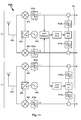
- FIG. 6 shows a schematic illustration of a broadband solution provided in the receiver 112a' comprising a measuring unit 640a implementing the band-pass filters A, B, BW1 and BW2 described above.
- the receiver 112a' supports space diversity by using a first receiver branch and a second receiver branch.
- the first branch comprises an antenna 610 connected to an I-channel mixer 612 and a Q-channel mixer 614, an oscillator 616 connected to a 90° phase changer 618 which in turn is connected to the two mixers 612, 614 for down converting the signal received by the antenna 610 and creating the I- and Q-channel.
- the second branch comprises an antenna 620 connected to an I-channel mixer 622 and a Q-channel mixer 624, an oscillator 616 connected to a 90° phase changer 628 which in turn is connected to the two mixers 622, 624 for down converting the signal received by the antenna 620 and creating the I- and Q-channel.
- the parts and functions of the receiver 112a' described above are well known to those skilled in the art and they need no further description.
- the first diversity branch of the embodiment in Fig. 6 comprises the above described first band-pass filter A and second band-pass filter B for measuring the linear term a 1 ⁇ T of the interfering signal S i in the second channel n+1.
- the first and second band-pass filters A and B is each connected to both the I-channel and the Q-channel of the first diversity branch.
- the second diversity branch comprises the third and the fourth band-pass filter BW1 and BW2 for measuring the third order nonlinear term a 3 ⁇ T 3 of the signals detected by filters A and B.
- the third and the fourth band-pass filter BW1 and BW2 is each connected to both the I-channel and the Q-channel of the second diversity branch.
- the calculation unit 650a is connected to the outputs of the band-pass filters A, B, BW1, BW2 so as to be provided with the filtered signals from these filters.
- the calculation unit 650a may be implemented by means of hardware and/or software, and it may comprise one or several hardware units and/or software modules, e.g. one or several separate processor arrangements provided with or having access to the appropriate software and hardware required for the functions to be performed.
- the transfer function of a general non ideal transmitter and the signals transmitted from such a transmitter can all be regarded as continuous, i.e. there are no discontinuities.
- the unknowns A , ⁇ A , ⁇ A , B , ⁇ B , ⁇ B i.e. the signal T
- a 1 , a 3 needed to define the model S T a 1 ⁇ T + a 3 ⁇ T 3 in expression (2)
- a curve fitting method e.g. like Newton's method or a Gauss-Newton algorithm or similar
- Figure 7 shows a schematic illustration of a narrowband embodiment of the present invention provided in the receiver 112a' comprising a measuring unit 640b implementing the band-pass filters A, B and BW1 described above.
- the receiver 112a' supports space diversity in the same manner as described above with reference to Fig. 6 .
- the first diversity branch of the embodiment in Fig. 7 comprises the first and second band-pass filters A and B for measuring the linear term a 1 ⁇ T of the interfering signal S i in the same manner as described above with reference to Fig. 6 .
- the second diversity branch only comprises the third band-pass filter BW1 for measuring the third order nonlinear term a 3 ⁇ T 3 of the signals detected by filters A and B.
- the third band-pass filter BW1 operates in the same manner as described above with reference to Fig. 6 .
- the second diversity branch can be arranged for a narrowband reception within channel n only.
- the 90° phase changer 618 is still connected to the oscillator 616, whereas the 90° phase changer 628 is connected to another oscillator 616'.
- Figure 8 shows a schematic illustration of an alternative narrowband embodiment of the present invention provided in the receiver 112a' comprising a measuring unit 640c implementing the band-pass filters A, B, BW1 and BW2 described above.
- the receiver 112a' in Fig. 8 supports space diversity in the same manner as described above with reference to Fig. 6 and Fig. 7 , i.e. it is assumed that the receiver 112a' comprises a first diversity branch and a second diversity branch (not shown in Fig. 8 , see Fig. 11 ).
- the first diversity branch comprises the first and second band-pass filters A and B for measuring the linear term a 1 ⁇ T of the interfering signal S i , and the second and third band-pass filters BW1 and BW2 for measuring the third order nonlinear term a 3 ⁇ T 3 of the signals detected by filters A and B.
- the band-pass filters A, B, BW1 and BW2 operate in the same manner as described above with reference to Fig. 6 .
- the second diversity branch (not shown in Fig. 8 ) can be arranged for a narrowband reception within channel n only.
- the model is set up and defined (i.e. implemented) in a transmitter-model unit 660a of the access point 112a, see e.g. Fig.
- FIG. 9 showing a schematic illustration of an interfering reduction system implemented in the first access point 112a according to an embodiment of the present invention.
- the interfering reduction system in Fig. 9 utilizes the measuring unit 640a and the calculation unit 650a previously described with reference to Fig. 6 .
- the calculation unit 650a is connected to the transmitter-model unit 660a for communicating the signal T and the coefficients a 1 , a 3 so that the transmitter-model unit 660a can set up and define the assumed model in (2).
- Fig. 9 shows a schematic illustration of an interfering reduction system implemented in the first access point 112a according to an embodiment of the present invention.
- the interfering reduction system in Fig. 9 utilizes the measuring unit 640a and the calculation unit 650a previously described with reference to Fig. 6 .
- the calculation unit 650a is connected to the transmitter-model unit 660a for communicating the signal T and the coefficients a 1 , a 3 so that the transmitter-model unit 660a can set up and
- the measuring unit 640a since the measuring unit 640a is used it follows that the receiver filters 672a, 674a in the first diversity branch are tuned to cover the frequency channel n+1 whereas the receiver filters 676a, 678a in the second diversity branch are tuned to cover the frequency channels n, n+1 and n+2.
- the wanted signal S w can only be detected in the second diversity branch, at least during setup of the assumed model in (2).
- a detection of the wanted signal S w can only be made through a broadly defined frequency span comprising all the channels n, n+1 and n+2, which will decrease the performance, e.g. with respect to the signal to interference ratio (SIR).
- SIR signal to interference ratio
- FIG. 10 An alternative interfering reduction system is shown in Fig. 10 which utilizes the measuring unit 640b and the calculation unit 650b previously described with reference to Fig. 7 .
- the interfering reduction system in Fig. 10 is the same or similar as the one previously described with reference to Fig. 9 .
- the measuring unit 640b since the measuring unit 640b is used it follows that the receiver filters 672a, 674a in the first diversity branch are tuned to cover the frequency channel n+1, whereas the receiver filters 676a, 678a in the second diversity branch are tuned to cover the frequency channel n.
- a detection of the wanted signal S w can be made through a narrowly defined frequency span only comprising channel n, which will increase the performance, e.g. with respect to the signal to interference ratio (SIR).
- SIR signal to interference ratio
- FIG. 11 Another alternative interfering reduction system is shown in Fig. 11 which utilizes the measuring unit 640c and the calculation unit 650a previously described with reference to Fig. 6 and Fig. 8 .
- the interfering reduction system in Fig. 11 is the same or similar as the one previously described with reference to Fig. 9 and Fig. 10 .
- the measuring unit 640c since the measuring unit 640c is used it follows that the receiver filters 672a, 674a in the first diversity branch are tuned to cover the frequency channels n, n+1 and n+2, whereas the receiver filters 676a, 678a in the second diversity branch can be tuned to only cover the frequency channel n.
- a detection of the wanted signal S w can be made through a narrowly defined frequency span only comprising channel n, which will increase the performance, e.g. with respect to the signal to interference ratio (SIR).
- the measuring unit 640c will only affect the first diversity branch, whereas the second diversity branch can be left as it is for a continuous detection of the wanted signal S w . This has the potential of simplifying the implementation of the reduction system in Fig. 11 .
- a fifth step S5 of the exemplifying method it is preferred that the part of the interfering signal S i occurring in the wanted channel n is subtract from the signal detected by the receiver 112a' in the wanted channel n.
- the coefficients a 1 and a 3 may also be solved defined and set up in the transmitter-model unit 660a, 660b in a continuous manner, but assuming that the transfer function of the transmitter 112b' is stable over time this may be done at a lower periodicity.
- the I-channel of the interfering signal S i is then filtered by a first band-pass filter 914a of the second diversity branch tuned into the wanted channel n so as to produce the parts of the interfering signal S i occurring in the wanted channel n.
- the Q-channel of the interfering signal S i is then filtered by a second band-pass filter 914b of the second diversity branch tuned into the wanted channel n so as to produce the parts of the interfering signal S i occurring in the wanted channel n. These parts are then subtracted from the I-channel and the Q-channel respectively comprising the signal detected by the receiver 112a in the channel n, i.e. detected by the second diversity branch.
- Fig. 11 the above can be done in a slightly different manner.
- the output signal S T corresponding to the interfering signal S i is accomplished in the same or similar manner as described above and the parts of the interfering signal S i occurring in the I- and Q-channel of the signal detected by the receiver 112a in channel n is subtracted in the same or similar manner as described above.
- the I-channel of the interfering signal S i may also be filtered by a third band-pass filter 912a tuned into the wanted channel n so as to produce the parts of the interfering signal S i occurring in the wanted channel n, whereas the Q-channel of the interfering signal S i may be filtered by a fourth band-pass filter 912b tuned into the wanted channel n so as to produce the parts of the interfering signal S i occurring in the wanted channel n.
- These parts may then be subtracted from the I-channel and the Q-channel respectively comprising the signal detected by the receiver 112a in the channel n, i.e. detected by the first diversity branch.
- a delay function may be required in Fig. 9 , 10 and 11 to compensate for the delay caused by the operation in the measure, solve and subtract functions.
- Such an delay may e.g. be introduced in each diversity branch after the receiver filter filters 672a, 674a, 676a, 678a respectively but before the subtraction point.
- the wanted signal S w will be part of the measurement within the band-pass filter BW1 and a third signal might be part of measurement in the band-pass filter BW2. If one is to use the measurement within BW2 then the third signal has to be low. If the wanted signal is 16dB below the interfering signal within the wanted channel (Y-X) then it will influence the amplitude by 0.1 dB.
- the wanted signal S w , the third signal and the interfering signal S i are typically uncorrelated.
- One solution is to use average when calculating the unknowns A , ⁇ A , ⁇ A , B , ⁇ B , ⁇ B . Over time the error introduced from the wanted signal and the third signal is averaged out.
- a third solution is to use a trial and error technique to find the phase and amplitude that lower the interferer signal and preserves the wanted signal.
- the invention increases the receiver sensitivity in tough interfering environments. Moreover, the invention makes the wireless connection more reliable for e.g. emergency calls. No extra components needed, since the filters etc can be implemented by means of software.
Landscapes
- Engineering & Computer Science (AREA)
- Computer Networks & Wireless Communication (AREA)
- Signal Processing (AREA)
- Mobile Radio Communication Systems (AREA)
Claims (13)
- Methode zur Reduzierung des Einflusses eines Störsignals (Si ) auf ein gewünschtes Signal (Sw ) in einem ersten Frequenzkanal (n), welches von einem Empfänger (112a') empfangen wird, wenn das Störsignal (Si ) in einem zweiten Frequenzkanal (n+1) in der Nähe des ersten Kanals (n) auftritt, wobei die Methode an einem Zugangspunkt (112a) folgende Schritte umfasst:- Annahme eines Modells (ST ) eines Transmitters (120b'), das Störsignal (Si ) bewirkend,- Einholung im ersten Kanal (n) eines Messwerts des gewünschten Signals (Sw ) und eines Messwerts eines nicht-linearen Teils des Störsignals (Si ), und im zweiten Kanal (n+1) eines Messwerts eines linearen Teils des Störsignals (Si ),- Lösung des Modells für den besagten Transmitter (120b') durch Verwendung des gemessenen linearen und nicht-linearen Teils,- Einholung des Störsignals (Si ), welches den ersten Kanal (n) beeinflusst, durch Verwendung des gelösten Modells und Subtraktion des eingeholten Störsignals (Si ) vom gewünschten Signal (Sw ), welches vom Empfänger (112a') empfangen worden ist.
- Methode gemäß Anspruch 1, worin die Methode folgende Schritte umfasst:- Einholung, in einem dritten Frequenzkanal (n+2) in der Nähe des zweiten Frequenzkanals (n+1), eines zusätzlichen Messwerts des besagten nicht-linearen Teils des Störsignals (Si ).
- Methode gemäß einem der Ansprüche 1 oder 2, worin der besagte Empfänger (112a') einen ersten Empfangszweig (B1) und einen zweiten Empfangszweig (B2) zur Unterstützung von Raumdiversity umfasst, wobei die Methode folgende Schritte umfasst:- Einholung des besagten gewünschten Signals (Sw ) und des besagten nicht-linearen Teils des Störsignals (Si ) durch Messung im zweiten Zweig (B2), und- Einholung des besagten linearen Teils des Störsignals (Si ) durch Messung im ersten Zweig (B1).
- Methode gemäß Anspruch 1, worin der besagte Empfänger (112a') einen ersten Empfangszweig (B1) und einen zweiten Empfangszweig (B2) zur Unterstützung von Raumdiversity umfasst, wobei die Methode folgende Schritte umfasst:- Einholung des besagten gewünschten Signals (Sw ) durch Messung im zweiten Zweig (B2), und- Einholung des besagten nicht-linearen Teils des Störsignals (Si ) und des besagten linearen Teils des Störsignals (Si ) durch Messung im ersten Zweig (B1).
- Methode gemäß einem der vorstehenden Ansprüche, wobei die Methode folgende Schritte umfasst:- Lösung des Modells (ST ) in Bezug auf die bezeichnenden Parameter der linearen Eigenschaften (a 1, a 3) des Originalsignals, sowie des, dem Transmitter (120b') eingespeisten Originalsignals (T), welches das Störsignal (Si) verursacht, und- Einholung des Störsignals (Si ) im ersten Kanal (n) durch Bereitstellung der besagten Parameter (a 1, a 3, T) an das gelöste Modell und Filtrierung des eingeholten Störsignals (Si ) durch einen Filter, der auf den ersten Kanal (n) eingestellt ist.
- Methode gemäß einem der vorstehenden Ansprüche, wobei die Methode folgende Schritte umfasst:- Lösung des Modells (ST ) mit Hilfe einer Curve-Fitting-Methode (Kurvenanpassungsmethode).
- Methode gemäß einem der vorstehenden Ansprüche 1, 3, 4, 5, wobei die Methode folgende Schritte umfasst:- Einholung im zweiten Kanal (n+1) einer Messung des besagten linearen Teils des Störsignals (Si ) durch Verwendung eines ersten Bandpassfilters (A), der auf eine erste Grenze der Frequenzspanne (x) des Störsignals (Si ) eingestellt ist, sowie eines zweiten Bandpassfilters (B), der auf eine zweite Grenze der Frequenzspanne (x) des Störsignals (Si ) eingestellt ist, und- Einholung im ersten Kanal (n) einer Messung des besagten nicht-linearen Teils des Störsignals (Si ) durch Verwendung eines dritten Bandpassfilters (BW1), der auf eine Nicht-Linearität der von dem besagten ersten und zweiten Bandpassfilter (A, B) erfassten Signale eingestellt ist.
- Methode gemäß Anspruch 7, worin die besagten Bandpassfilter (A, B, BW1) schmale Bandpassfilter sind, welche so konfiguriert sind, dass sie im Wesentlichen eine einzige Frequenz erfassen.
- Methode gemäß Anspruch 2, wobei die Methode folgende Schritte umfasst:- Einholung im zweiten Kanal (n+1) eines Messwerts des besagten linearen Teils des Störsignals (Si ) durch Verwendung eines ersten Bandpassfilters (A), welcher auf eine erste Grenze der Frequenzspanne (x) des Störsignals (Si ) eingestellt ist, und eines zweiten Bandpassfilters (B), der auf eine zweite Grenze der Frequenzspanne (x) des Störsignals (Si ) eingestellt ist, und- Einholung im ersten Kanal (n) eines Messwerts des besagten nicht-linearen Teils des Störsignals (Si ) durch Verwendung eines dritten Bandpassfilters (BW1), der auf eine Nicht-Linearität der von dem besagten ersten und zweiten Bandpassfilter (A, B) erfassten Signale eingestellt ist, und- Einholung in einem dritten Frequenzkanal (n+2) eines Messwerts des besagten nicht-linearen Teils des Störsignals (Si ) durch Verwendung eines vierten Bandpassfilters (BW2), der auf eine Nicht-Linearität der von dem besagten ersten und zweiten Bandpassfilter (A, B) erfassten Signale eingestellt ist.
- Methode gemäß Anspruch 9, worin die besagten Bandpassfilter (A, B, BW1, BW2) schmale Bandpassfilter sind, welche so konfiguriert sind, dass sie im Wesentlichen eine einzige Frequenz erfassen.
- Methode gemäß einem der vorstehenden Ansprüche, worin die besagten nicht-linearen Teile des Störsignals (Si ) ein drittklassiges nicht-lineares Teil des besagten linearen Teils des Störsignals (Si ) ist.
- Methode gemäß einem der vorstehenden Ansprüche, worin das Modell des Transmitters (120b'), welcher das Störsignals (Si ) wie folgt angenommen wird:

T das Originalsignal, welches in den Transmitter (120b') eingespeist ist, a 1 • T ein linearer Term ist, mit a 1 • = Gewinn des Transmitters (120b') und der Term a 3 • T 3 die drittklassige Nicht-Linearität des Transmitters (120b) definiert. - Zugangspunkt (112a), umfassend:- eine Messeinheit (640a, 640b, 640c), geeignet zur Durchführung von Messungen in den ersten und zweiten Kanälen,- eine Berechnungseinheit (650a, 650b), geeignet zur Lösung eines angenommenen Modelle eines Transmitters, wo die Berechnungseinheit (650a, 650b) an den Ausgang der Messeinheit (640a, 640b, 640c) angeschlossen ist,- eine Transmittermodell-Einheit (660a, 660b), geeignet zur Aufstellung und Definition des angenommenen Modells, wo die Transmittermodell-Einheit (660a, 660b) an den Ausgang der Berechnungseinheit (650a, 650b) angeschlossen ist,worin der Zugangspunkt (112a) konfiguriert ist, um die Methode gemäß einem beliebigen der Ansprüche 1-12 auszuführen.
Applications Claiming Priority (1)
| Application Number | Priority Date | Filing Date | Title |
|---|---|---|---|
| PCT/SE2008/050770 WO2009157829A1 (en) | 2008-06-25 | 2008-06-25 | Interferer reduction |
Publications (3)
| Publication Number | Publication Date |
|---|---|
| EP2291920A1 EP2291920A1 (de) | 2011-03-09 |
| EP2291920A4 EP2291920A4 (de) | 2015-07-22 |
| EP2291920B1 true EP2291920B1 (de) | 2016-09-28 |
Family
ID=41444748
Family Applications (1)
| Application Number | Title | Priority Date | Filing Date |
|---|---|---|---|
| EP08767236.6A Active EP2291920B1 (de) | 2008-06-25 | 2008-06-25 | Störerreduktion |
Country Status (3)
| Country | Link |
|---|---|
| US (1) | US8693954B2 (de) |
| EP (1) | EP2291920B1 (de) |
| WO (1) | WO2009157829A1 (de) |
Families Citing this family (3)
| Publication number | Priority date | Publication date | Assignee | Title |
|---|---|---|---|---|
| WO2010099050A2 (en) * | 2009-02-25 | 2010-09-02 | Elliott Hoole | Self-optimization in wireless base stations by detection of interference at the edge of a received radio frequency band |
| WO2012112112A1 (en) * | 2011-02-15 | 2012-08-23 | Telefonaktiebolaget Lm Ericsson (Publ) | A first network node and a second network node and methods therein |
| CN113472693A (zh) | 2018-08-02 | 2021-10-01 | 华为技术有限公司 | 一种网络资源的调度方法和装置 |
Family Cites Families (10)
| Publication number | Priority date | Publication date | Assignee | Title |
|---|---|---|---|---|
| DE69934864T2 (de) * | 1998-05-20 | 2007-10-18 | Ntt Docomo Inc. | Interferenzloses radiokommunikationssystem |
| US6765531B2 (en) * | 1999-01-08 | 2004-07-20 | Trueposition, Inc. | System and method for interference cancellation in a location calculation, for use in a wireless location system |
| JP2002319908A (ja) * | 2001-02-13 | 2002-10-31 | Advantest Corp | 隣接チャネル漏洩電力比測定装置およびチャネル電力測定装置、方法、プログラム、および該プログラムを記録した記録媒体 |
| US7043208B2 (en) * | 2002-10-15 | 2006-05-09 | Motorola, Inc. | Method and apparatus to reduce interference in a communication device |
| US7079828B1 (en) * | 2002-10-25 | 2006-07-18 | Edgewater Computer Systems, Inc. | Method and apparatus for side-lobe cancellation in wideband radio systems |
| US20050095985A1 (en) * | 2003-10-31 | 2005-05-05 | Abdulrauf Hafeoz | Method and apparatus for multi-user interference determination an rejection |
| WO2005064808A1 (en) * | 2003-12-23 | 2005-07-14 | Telefonaktiebolaget L M Ericsson (Publ) | A method of and a communication device for adjacent channel interference cancellation in a radio telecommunication system |
| US7583755B2 (en) * | 2005-08-12 | 2009-09-01 | Ati Technologies, Inc. | Systems, methods, and apparatus for mitigation of nonlinear distortion |
| CN101233711B (zh) * | 2005-10-24 | 2012-11-21 | 松下电器产业株式会社 | 干扰信号特征量存储方法和装置、干扰信号特征量获取方法和装置、干扰信号抑制方法和装置 |
| US8170487B2 (en) * | 2006-02-03 | 2012-05-01 | Qualcomm, Incorporated | Baseband transmitter self-jamming and intermodulation cancellation device |
-
2008
- 2008-06-25 US US12/999,531 patent/US8693954B2/en active Active
- 2008-06-25 EP EP08767236.6A patent/EP2291920B1/de active Active
- 2008-06-25 WO PCT/SE2008/050770 patent/WO2009157829A1/en active Application Filing
Also Published As
| Publication number | Publication date |
|---|---|
| EP2291920A4 (de) | 2015-07-22 |
| EP2291920A1 (de) | 2011-03-09 |
| US8693954B2 (en) | 2014-04-08 |
| US20110092162A1 (en) | 2011-04-21 |
| WO2009157829A1 (en) | 2009-12-30 |
Similar Documents
| Publication | Publication Date | Title |
|---|---|---|
| EP3369182B1 (de) | Empfänger mit erkennung von passiver intermodulation an einem zellenstandort | |
| US8280442B2 (en) | Radio base station and receiver fault diagnosis method | |
| JP3782616B2 (ja) | ブースター、監視装置、ブースター・システム、制御方法および監視方法 | |
| EP2301215B1 (de) | Verfahren und system zur erkennung von nachbarkanalinterferenzen für ofdm/ofdma-basierten breitband-drahtloszugang | |
| EP2474099B1 (de) | Scanner für funkumgebung | |
| GB2502279A (en) | Reduction of interference due to intermodulation | |
| CN111132211B (zh) | 上行干扰类型的检测方法及装置 | |
| US9118285B2 (en) | Compensation of a transmitter distortion | |
| JP2004254243A (ja) | 干渉測定評価システム | |
| EP2291920B1 (de) | Störerreduktion | |
| EP3155850B1 (de) | Robustes pbch-ic-verfahren in lte-advanced | |
| CN104469786A (zh) | 一种lte与wifi共基站干扰抑制系统及方法 | |
| JP6143956B2 (ja) | 複数のチャネルを使用してサービスを取得するためのシステムおよび方法 | |
| JP5537211B2 (ja) | 無線基地局 | |
| KR101988990B1 (ko) | 기지국에서의 핸드오버 방법 | |
| CN106788813B (zh) | 一种干扰信号检测、消除装置、方法以及移动终端 | |
| EP4000183A1 (de) | Pim-unterdrückung | |
| Waheed et al. | Modeling and digital suppression of passive nonlinear distortion in simultaneous transmit—Receive systems | |
| JP5537212B2 (ja) | 無線基地局 | |
| KR100758883B1 (ko) | 중계기의 디지탈 다중경로 신호정합기 | |
| Tikhvinskiy et al. | Experimental test results of EMC between 5G and Radio relay links in millimeter band | |
| JP4409333B2 (ja) | 異周波測定方法 | |
| JP2010177922A (ja) | 基地局、基地局の制御方法 | |
| WO2014164657A1 (en) | Method and apparatus for absorbed power calibration for ue | |
| Rouco et al. | Public Mobile Wideband Networks Interference Impact Assessment on Railways GSM-R Network |
Legal Events
| Date | Code | Title | Description |
|---|---|---|---|
| PUAI | Public reference made under article 153(3) epc to a published international application that has entered the european phase |
Free format text: ORIGINAL CODE: 0009012 |
|
| 17P | Request for examination filed |
Effective date: 20101110 |
|
| AK | Designated contracting states |
Kind code of ref document: A1 Designated state(s): AT BE BG CH CY CZ DE DK EE ES FI FR GB GR HR HU IE IS IT LI LT LU LV MC MT NL NO PL PT RO SE SI SK TR |
|
| AX | Request for extension of the european patent |
Extension state: AL BA MK RS |
|
| DAX | Request for extension of the european patent (deleted) | ||
| RA4 | Supplementary search report drawn up and despatched (corrected) |
Effective date: 20150619 |
|
| RIC1 | Information provided on ipc code assigned before grant |
Ipc: H04B 1/12 20060101AFI20150615BHEP Ipc: H04B 1/10 20060101ALI20150615BHEP |
|
| GRAP | Despatch of communication of intention to grant a patent |
Free format text: ORIGINAL CODE: EPIDOSNIGR1 |
|
| GRAP | Despatch of communication of intention to grant a patent |
Free format text: ORIGINAL CODE: EPIDOSNIGR1 |
|
| INTG | Intention to grant announced |
Effective date: 20160301 |
|
| INTG | Intention to grant announced |
Effective date: 20160314 |
|
| GRAP | Despatch of communication of intention to grant a patent |
Free format text: ORIGINAL CODE: EPIDOSNIGR1 |
|
| INTG | Intention to grant announced |
Effective date: 20160520 |
|
| GRAS | Grant fee paid |
Free format text: ORIGINAL CODE: EPIDOSNIGR3 |
|
| GRAA | (expected) grant |
Free format text: ORIGINAL CODE: 0009210 |
|
| AK | Designated contracting states |
Kind code of ref document: B1 Designated state(s): AT BE BG CH CY CZ DE DK EE ES FI FR GB GR HR HU IE IS IT LI LT LU LV MC MT NL NO PL PT RO SE SI SK TR |
|
| REG | Reference to a national code |
Ref country code: GB Ref legal event code: FG4D |
|
| REG | Reference to a national code |
Ref country code: CH Ref legal event code: EP |
|
| REG | Reference to a national code |
Ref country code: AT Ref legal event code: REF Ref document number: 833523 Country of ref document: AT Kind code of ref document: T Effective date: 20161015 |
|
| REG | Reference to a national code |
Ref country code: IE Ref legal event code: FG4D |
|
| REG | Reference to a national code |
Ref country code: DE Ref legal event code: R096 Ref document number: 602008046531 Country of ref document: DE |
|
| REG | Reference to a national code |
Ref country code: LT Ref legal event code: MG4D |
|
| PG25 | Lapsed in a contracting state [announced via postgrant information from national office to epo] |
Ref country code: NO Free format text: LAPSE BECAUSE OF FAILURE TO SUBMIT A TRANSLATION OF THE DESCRIPTION OR TO PAY THE FEE WITHIN THE PRESCRIBED TIME-LIMIT Effective date: 20161228 Ref country code: FI Free format text: LAPSE BECAUSE OF FAILURE TO SUBMIT A TRANSLATION OF THE DESCRIPTION OR TO PAY THE FEE WITHIN THE PRESCRIBED TIME-LIMIT Effective date: 20160928 Ref country code: LT Free format text: LAPSE BECAUSE OF FAILURE TO SUBMIT A TRANSLATION OF THE DESCRIPTION OR TO PAY THE FEE WITHIN THE PRESCRIBED TIME-LIMIT Effective date: 20160928 Ref country code: HR Free format text: LAPSE BECAUSE OF FAILURE TO SUBMIT A TRANSLATION OF THE DESCRIPTION OR TO PAY THE FEE WITHIN THE PRESCRIBED TIME-LIMIT Effective date: 20160928 |
|
| REG | Reference to a national code |
Ref country code: NL Ref legal event code: MP Effective date: 20160928 |
|
| REG | Reference to a national code |
Ref country code: AT Ref legal event code: MK05 Ref document number: 833523 Country of ref document: AT Kind code of ref document: T Effective date: 20160928 |
|
| PG25 | Lapsed in a contracting state [announced via postgrant information from national office to epo] |
Ref country code: GR Free format text: LAPSE BECAUSE OF FAILURE TO SUBMIT A TRANSLATION OF THE DESCRIPTION OR TO PAY THE FEE WITHIN THE PRESCRIBED TIME-LIMIT Effective date: 20161229 Ref country code: NL Free format text: LAPSE BECAUSE OF FAILURE TO SUBMIT A TRANSLATION OF THE DESCRIPTION OR TO PAY THE FEE WITHIN THE PRESCRIBED TIME-LIMIT Effective date: 20160928 Ref country code: SE Free format text: LAPSE BECAUSE OF FAILURE TO SUBMIT A TRANSLATION OF THE DESCRIPTION OR TO PAY THE FEE WITHIN THE PRESCRIBED TIME-LIMIT Effective date: 20160928 Ref country code: LV Free format text: LAPSE BECAUSE OF FAILURE TO SUBMIT A TRANSLATION OF THE DESCRIPTION OR TO PAY THE FEE WITHIN THE PRESCRIBED TIME-LIMIT Effective date: 20160928 |
|
| PG25 | Lapsed in a contracting state [announced via postgrant information from national office to epo] |
Ref country code: EE Free format text: LAPSE BECAUSE OF FAILURE TO SUBMIT A TRANSLATION OF THE DESCRIPTION OR TO PAY THE FEE WITHIN THE PRESCRIBED TIME-LIMIT Effective date: 20160928 Ref country code: RO Free format text: LAPSE BECAUSE OF FAILURE TO SUBMIT A TRANSLATION OF THE DESCRIPTION OR TO PAY THE FEE WITHIN THE PRESCRIBED TIME-LIMIT Effective date: 20160928 |
|
| PG25 | Lapsed in a contracting state [announced via postgrant information from national office to epo] |
Ref country code: PT Free format text: LAPSE BECAUSE OF FAILURE TO SUBMIT A TRANSLATION OF THE DESCRIPTION OR TO PAY THE FEE WITHIN THE PRESCRIBED TIME-LIMIT Effective date: 20170130 Ref country code: SK Free format text: LAPSE BECAUSE OF FAILURE TO SUBMIT A TRANSLATION OF THE DESCRIPTION OR TO PAY THE FEE WITHIN THE PRESCRIBED TIME-LIMIT Effective date: 20160928 Ref country code: IS Free format text: LAPSE BECAUSE OF FAILURE TO SUBMIT A TRANSLATION OF THE DESCRIPTION OR TO PAY THE FEE WITHIN THE PRESCRIBED TIME-LIMIT Effective date: 20170128 Ref country code: BE Free format text: LAPSE BECAUSE OF FAILURE TO SUBMIT A TRANSLATION OF THE DESCRIPTION OR TO PAY THE FEE WITHIN THE PRESCRIBED TIME-LIMIT Effective date: 20160928 Ref country code: AT Free format text: LAPSE BECAUSE OF FAILURE TO SUBMIT A TRANSLATION OF THE DESCRIPTION OR TO PAY THE FEE WITHIN THE PRESCRIBED TIME-LIMIT Effective date: 20160928 Ref country code: BG Free format text: LAPSE BECAUSE OF FAILURE TO SUBMIT A TRANSLATION OF THE DESCRIPTION OR TO PAY THE FEE WITHIN THE PRESCRIBED TIME-LIMIT Effective date: 20161228 Ref country code: ES Free format text: LAPSE BECAUSE OF FAILURE TO SUBMIT A TRANSLATION OF THE DESCRIPTION OR TO PAY THE FEE WITHIN THE PRESCRIBED TIME-LIMIT Effective date: 20160928 Ref country code: PL Free format text: LAPSE BECAUSE OF FAILURE TO SUBMIT A TRANSLATION OF THE DESCRIPTION OR TO PAY THE FEE WITHIN THE PRESCRIBED TIME-LIMIT Effective date: 20160928 Ref country code: CZ Free format text: LAPSE BECAUSE OF FAILURE TO SUBMIT A TRANSLATION OF THE DESCRIPTION OR TO PAY THE FEE WITHIN THE PRESCRIBED TIME-LIMIT Effective date: 20160928 |
|
| REG | Reference to a national code |
Ref country code: FR Ref legal event code: PLFP Year of fee payment: 10 |
|
| REG | Reference to a national code |
Ref country code: DE Ref legal event code: R097 Ref document number: 602008046531 Country of ref document: DE |
|
| PG25 | Lapsed in a contracting state [announced via postgrant information from national office to epo] |
Ref country code: IT Free format text: LAPSE BECAUSE OF FAILURE TO SUBMIT A TRANSLATION OF THE DESCRIPTION OR TO PAY THE FEE WITHIN THE PRESCRIBED TIME-LIMIT Effective date: 20160928 |
|
| PG25 | Lapsed in a contracting state [announced via postgrant information from national office to epo] |
Ref country code: DK Free format text: LAPSE BECAUSE OF FAILURE TO SUBMIT A TRANSLATION OF THE DESCRIPTION OR TO PAY THE FEE WITHIN THE PRESCRIBED TIME-LIMIT Effective date: 20160928 |
|
| PLBE | No opposition filed within time limit |
Free format text: ORIGINAL CODE: 0009261 |
|
| STAA | Information on the status of an ep patent application or granted ep patent |
Free format text: STATUS: NO OPPOSITION FILED WITHIN TIME LIMIT |
|
| 26N | No opposition filed |
Effective date: 20170629 |
|
| PG25 | Lapsed in a contracting state [announced via postgrant information from national office to epo] |
Ref country code: SI Free format text: LAPSE BECAUSE OF FAILURE TO SUBMIT A TRANSLATION OF THE DESCRIPTION OR TO PAY THE FEE WITHIN THE PRESCRIBED TIME-LIMIT Effective date: 20160928 |
|
| PG25 | Lapsed in a contracting state [announced via postgrant information from national office to epo] |
Ref country code: MC Free format text: LAPSE BECAUSE OF FAILURE TO SUBMIT A TRANSLATION OF THE DESCRIPTION OR TO PAY THE FEE WITHIN THE PRESCRIBED TIME-LIMIT Effective date: 20160928 |
|
| REG | Reference to a national code |
Ref country code: CH Ref legal event code: PL |
|
| REG | Reference to a national code |
Ref country code: IE Ref legal event code: MM4A |
|
| PG25 | Lapsed in a contracting state [announced via postgrant information from national office to epo] |
Ref country code: LI Free format text: LAPSE BECAUSE OF NON-PAYMENT OF DUE FEES Effective date: 20170630 Ref country code: IE Free format text: LAPSE BECAUSE OF NON-PAYMENT OF DUE FEES Effective date: 20170625 Ref country code: CH Free format text: LAPSE BECAUSE OF NON-PAYMENT OF DUE FEES Effective date: 20170630 Ref country code: LU Free format text: LAPSE BECAUSE OF NON-PAYMENT OF DUE FEES Effective date: 20170625 |
|
| REG | Reference to a national code |
Ref country code: FR Ref legal event code: PLFP Year of fee payment: 11 |
|
| PG25 | Lapsed in a contracting state [announced via postgrant information from national office to epo] |
Ref country code: MT Free format text: LAPSE BECAUSE OF NON-PAYMENT OF DUE FEES Effective date: 20170625 |
|
| PG25 | Lapsed in a contracting state [announced via postgrant information from national office to epo] |
Ref country code: HU Free format text: LAPSE BECAUSE OF FAILURE TO SUBMIT A TRANSLATION OF THE DESCRIPTION OR TO PAY THE FEE WITHIN THE PRESCRIBED TIME-LIMIT; INVALID AB INITIO Effective date: 20080625 |
|
| PG25 | Lapsed in a contracting state [announced via postgrant information from national office to epo] |
Ref country code: CY Free format text: LAPSE BECAUSE OF NON-PAYMENT OF DUE FEES Effective date: 20160928 |
|
| PG25 | Lapsed in a contracting state [announced via postgrant information from national office to epo] |
Ref country code: TR Free format text: LAPSE BECAUSE OF FAILURE TO SUBMIT A TRANSLATION OF THE DESCRIPTION OR TO PAY THE FEE WITHIN THE PRESCRIBED TIME-LIMIT Effective date: 20160928 |
|
| PGFP | Annual fee paid to national office [announced via postgrant information from national office to epo] |
Ref country code: GB Payment date: 20220628 Year of fee payment: 15 |
|
| PGFP | Annual fee paid to national office [announced via postgrant information from national office to epo] |
Ref country code: FR Payment date: 20220627 Year of fee payment: 15 |
|
| PGFP | Annual fee paid to national office [announced via postgrant information from national office to epo] |
Ref country code: DE Payment date: 20220629 Year of fee payment: 15 |
|
| REG | Reference to a national code |
Ref country code: DE Ref legal event code: R119 Ref document number: 602008046531 Country of ref document: DE |
|
| GBPC | Gb: european patent ceased through non-payment of renewal fee |
Effective date: 20230625 |
|
| PG25 | Lapsed in a contracting state [announced via postgrant information from national office to epo] |
Ref country code: DE Free format text: LAPSE BECAUSE OF NON-PAYMENT OF DUE FEES Effective date: 20240103 Ref country code: GB Free format text: LAPSE BECAUSE OF NON-PAYMENT OF DUE FEES Effective date: 20230625 |