EP2291164B1 - Teat - Google Patents
Teat Download PDFInfo
- Publication number
- EP2291164B1 EP2291164B1 EP09761232.9A EP09761232A EP2291164B1 EP 2291164 B1 EP2291164 B1 EP 2291164B1 EP 09761232 A EP09761232 A EP 09761232A EP 2291164 B1 EP2291164 B1 EP 2291164B1
- Authority
- EP
- European Patent Office
- Prior art keywords
- mouthpiece
- teat
- tube
- opening
- suction
- Prior art date
- Legal status (The legal status is an assumption and is not a legal conclusion. Google has not performed a legal analysis and makes no representation as to the accuracy of the status listed.)
- Not-in-force
Links
Images


Classifications
-
- A—HUMAN NECESSITIES
- A61—MEDICAL OR VETERINARY SCIENCE; HYGIENE
- A61J—CONTAINERS SPECIALLY ADAPTED FOR MEDICAL OR PHARMACEUTICAL PURPOSES; DEVICES OR METHODS SPECIALLY ADAPTED FOR BRINGING PHARMACEUTICAL PRODUCTS INTO PARTICULAR PHYSICAL OR ADMINISTERING FORMS; DEVICES FOR ADMINISTERING FOOD OR MEDICINES ORALLY; BABY COMFORTERS; DEVICES FOR RECEIVING SPITTLE
- A61J11/00—Teats
- A61J11/04—Teats with means for fastening to bottles
- A61J11/045—Teats with means for fastening to bottles with interlocking means, e.g. protrusions or indentations on the teat
-
- A—HUMAN NECESSITIES
- A61—MEDICAL OR VETERINARY SCIENCE; HYGIENE
- A61J—CONTAINERS SPECIALLY ADAPTED FOR MEDICAL OR PHARMACEUTICAL PURPOSES; DEVICES OR METHODS SPECIALLY ADAPTED FOR BRINGING PHARMACEUTICAL PRODUCTS INTO PARTICULAR PHYSICAL OR ADMINISTERING FORMS; DEVICES FOR ADMINISTERING FOOD OR MEDICINES ORALLY; BABY COMFORTERS; DEVICES FOR RECEIVING SPITTLE
- A61J11/00—Teats
- A61J11/001—Teats having means for regulating the flow rate
- A61J11/0015—Teats having means for regulating the flow rate by size or shape of the opening
-
- A—HUMAN NECESSITIES
- A61—MEDICAL OR VETERINARY SCIENCE; HYGIENE
- A61J—CONTAINERS SPECIALLY ADAPTED FOR MEDICAL OR PHARMACEUTICAL PURPOSES; DEVICES OR METHODS SPECIALLY ADAPTED FOR BRINGING PHARMACEUTICAL PRODUCTS INTO PARTICULAR PHYSICAL OR ADMINISTERING FORMS; DEVICES FOR ADMINISTERING FOOD OR MEDICINES ORALLY; BABY COMFORTERS; DEVICES FOR RECEIVING SPITTLE
- A61J11/00—Teats
- A61J11/001—Teats having means for regulating the flow rate
- A61J11/002—Teats having means for regulating the flow rate by using valves
-
- A—HUMAN NECESSITIES
- A61—MEDICAL OR VETERINARY SCIENCE; HYGIENE
- A61J—CONTAINERS SPECIALLY ADAPTED FOR MEDICAL OR PHARMACEUTICAL PURPOSES; DEVICES OR METHODS SPECIALLY ADAPTED FOR BRINGING PHARMACEUTICAL PRODUCTS INTO PARTICULAR PHYSICAL OR ADMINISTERING FORMS; DEVICES FOR ADMINISTERING FOOD OR MEDICINES ORALLY; BABY COMFORTERS; DEVICES FOR RECEIVING SPITTLE
- A61J11/00—Teats
- A61J11/0035—Teats having particular shape or structure
- A61J11/0065—Teats having particular shape or structure for improving rigidity, e.g. anti-bite-through or anti-collapsing
Definitions
- the invention relates to a teat according to the preamble of patent claim 1 and a teat unit according to the preamble of claim 12 or 13.
- Teat nipples should be easy to attach and easy to clean. Furthermore, they should allow the infant to a possibly nature-inspired sucking, so that he can switch back and forth between the mother's breast and feeding bottle without Sauggefirrung.
- US 7 320 678 discloses, for example, a teat with a radially outwardly projecting flange and extending in the mouthpiece, projecting into the body of the teat cylindrical suction tube, through which the milk is sucked from the bottle to the suction port of the mouthpiece.
- This suction tube must be inserted into a corresponding receiving tube of the receiving unit. This is relatively difficult to do. Furthermore, this teat can be poorly cleaned.
- US 1 904 710 discloses a teat which folds down at a first location.
- US 5,897,007 describes a teat with an inner tube with a suction channel, which is formed in the region of the upper end of the mouthpiece.
- the inventive suction nipple for connection to a receiving unit of a beverage container has a main body and an adjoining the main body, tapered relative to the main body mouthpiece with at least one suction port through which the liquid exits the teat to the outside, and a free end.
- the teat has a first connecting element for connection to the receiving unit and a second connecting element for connection to the receiving unit and a suction channel.
- the suction channel runs in the mouthpiece. It opens with a first end in the suction opening and is directed with a second end to the base body. This second end forms the first connection element for sealing connection with the receiving unit.
- the main body is designed to be foldable towards the free end of the mouthpiece, and the teat is further designed to be foldable at at least one second location.
- the teat has a stable ground state, a first stable folded state and at least a second stable folded state, wherein the at least second stable state differs in the external appearance from the first stable state and the ground state.
- the mouthpiece has two sections, wherein the mouthpiece is designed such that it can be folded over in the transition area between these two sections.
- the mouthpiece in a region between its free end and its transition to the main body designed umklappbar.
- the suction channel extends at least partially in a tube which extends at least partially inside the mouthpiece and spaced from an inside of the mouthpiece.
- the tube has a first tube end connected to the mouthpiece.
- a second free tube end forms the second end of the suction channel.
- the first end of the tube ends at a distance from the free end of the mouthpiece inside the mouthpiece.
- the suction opening is in the free end of the mouthpiece, i. in its foremost tip and consists of a single hole.
- the suction opening can also be arranged not laterally in the tip, but laterally in the front region of the mouthpiece. It can also be formed in both variants by several holes.
- the first connecting means seals the connection of the suction channel with the receiving unit and thus with the interior of the beverage container against the remaining teat and thus against the outside.
- the teat itself is but mainly by the second connecting means, preferably a circumferential flange of the body, connected to the receiving unit. This connection is subject to standards that must be met. The nipple should not come off the beverage container during suckling when the baby is sucking or pulling on it.
- the first connecting element Since the main body is folded down or everted in the first appearance, the first connecting element is more accessible. It is easier to connect to the recording unit.
- the tube can relatively easily be pushed back into the mouthpiece from the second everted state and thus restore the normal position of use.
- This can be achieved, for example, by designing the mouthpiece to be conical at least over the area penetrated by the tube and / or to make the tube hollow-cylindrical in this area.
- Another advantage is that the simple and in particular the double-folded teat can be better cleaned because any complex structures in the interior of the body, such as the first connecting element, are exposed and are more accessible for the purpose of cleaning.
- the suction nipple can be produced in one piece, for example, even in a simple and in particular in a doubly folded state. This facilitates on the one hand the production and lowers the production costs. Furthermore, the inner region of the teat, in particular the space between the tube and mouthpiece, can be provided more easily with radial or axial ribs, dents, nubs or other internal structures.
- the mouthpiece in a top, the suction opening adjacent region is single-walled and executed in a lower, the base body adjacent region double-walled.
- the teat In the folded state of the body surfaces are exposed to the touch, which are not in contact with a liquid flowing through the teat under normal use of the teat, wherein the teat is connected by holding these surfaces with the receiving unit as intended.
- the teat is connectable without additional tools or tools with the receiving unit or mounted on this.
- the folded body can be touched on its inside and the mouthpiece must not be touched at any time. Since inside the main body of the tubular suction channel is present, and the inside of the body does not come into contact with the liquid to be drunk.
- the suction channel extends between the first tube end and the suction opening in a chamber in the interior of the mouthpiece.
- This chamber changes its shape during suction and adapts to the baby's sucking process and mouth similar to the natural nipple of the mother's breast.
- the mouthpiece and the tube are bendable at least in the region of the chamber, in order to adapt to the suction optimally and as lifelike as possible.
- This nipple allows a lifelike replica, so that Saugverwirrung can be avoided when changing from teat to the natural mother's breast.
- spacers may be arranged in the form of radial or axial ribs, nubs, dimples or other surface structures which prevent the walls of the tube and mouthpiece from sticking or sticking together during the suction process.
- the inventive teat can be used in a teat unit for sucking a liquid from a liquid container.
- This Saugnippeltechnik has the teat and a flow restrictor with a through hole.
- the teat has a mouthpiece and an integrally formed on the mouthpiece, extending towards the mouthpiece body, wherein in the mouthpiece a suction opening is present.
- the flow restrictor determines a maximum flow of liquid flowing from the liquid container through the suction opening.
- the flow restrictor is arranged outside the mouthpiece.
- the suction opening has a larger cross-sectional area than the passage opening of the flow restrictor.
- This teat unit allows a lifelike sucking. Thanks to the large opening, the mouthpiece, also called nipple, can be deformed well during the suction process, and it optimally adapts to the movements of the baby's mouth and tongue. The infant gets a similar sensation in the mouth as if it were sucking on a natural nipple of a mother's breast.
- the mouthpiece is designed to be bendable, and in intended use, preferably no parts which stiffen the mouthpiece over a substantial part of its length project into it. In the intended use, the mouthpiece is therefore preferably deformable.
- Typical diameters for a round suction opening are 3 to 8 mm and for a round flow limiter 0.2 to 0.7 mm.
- the flow restrictor is located outside the mouthpiece, i. outside of that part which is put into the mouth by the infant in the intended use. As a result, the infant can not influence the flow restrictor by mechanical pressure or tension caused by his lip and mouth movements.
- the teat according to the invention can also be used in a teat unit for sucking a liquid from a liquid container which has the teat and a flow restrictor with a passage opening.
- the teat has a mouthpiece and an integrally formed on the mouthpiece, extending towards the mouthpiece body, wherein in the mouthpiece a suction opening is present.
- the flow restrictor determines a maximum flow of liquid flowing from the liquid container through the suction opening.
- the flow restrictor is arranged outside the mouthpiece and the teat unit is arranged has a one-way valve which is located outside the mouthpiece, and wherein the flow restrictor is disposed in the one-way valve or in an adjacent region thereto.
- This Saugnippelü allows lifelike as possible, since in the suction unit only atmospheric pressure or negative pressure is present. There is no overpressure. The milk thus does not splash into the baby's mouth, but flows into the mouth according to the vacuum applied by the baby. The milk flow is approximately proportional to the vacuum applied by the infant.
- This Saugnippelü allows a suction, which is purely vacuum-controlled and largely independent of the rest, in particular the peristaltic movement of the tongue. If the posterior region of the tongue moves towards the upper palate, no milk should flow. If this rear area moves away from the upper palate, the milk flows.
- This teat unit takes into account the fact that the baby does not switch back and forth between vacuum and atmospheric pressure when sucking. It rather maintains a base vacuum throughout the suction process. In contrast to the arrangements according to the prior art now closes the valve upon reaching this base vacuum. If the absolute value of the applied vacuum rises above this basic vacuum, the valve opens and the milk or liquid can flow. The baby is thus able to take a break despite being able to maintain the basic vacuum, to take a breath or to recover, and to gather new strength, as happens with the mother's breast.
- the device according to the invention opens even at a low negative pressure of 1 to 90 mmHg, preferably 20 to 70 mmHg. Even more preferred values are between 20 to 30 mmHg and 5 to 30 mmHg. These values are in their absolute value just above a typical base vacuum of a baby.
- valve has no further influence on the milk flow during the suction process.
- the degree of opening and operation of the valve does not affect the flow of milk through the suction port.
- the check valve covers the passage opening of the flow restrictor. In a preferred embodiment, however, the check valve does not cover the relatively small passage opening of the flow restrictor but a larger opening.
- This opening is preferably arranged in the flow direction of the liquid in front of the flow restrictor, i. So directed to the liquid container. However, it can also be arranged downstream of the flow restrictor in the direction of flow.
- the opening of the flow restrictor is in the rigidly formed valve seat, i. here in the base part.
- this opening can be covered and closed by the valve membrane.
- it can also be arranged adjacent and lead into the dead volume.
- the opening of the flow restrictor can be arranged in the valve membrane and closed by sealing support of the membrane on the valve seat.
- the outflow opening is arranged adjacent to the valve seat and is not closed by the membrane, but leads into the dead volume.
- the outflow opening can be made the same size or larger than the opening of the flow restrictor.
- the flow restrictor can thus be arranged in, above or below the valve membrane.
- valve and the flow restrictor or the outlet opening and the valve are arranged adjacent to each other, the dead volume, in which also a vacuum must be generated, minimized.
- the valve or the sucker works too flawless at low flow rates.
- the valve is easy to disassemble and therefore easy to clean the teat unit. If a membrane is used, it can be held by clamping between individual parts.
- an umbrella valve instead of a clamped membrane with or without a well-defined opening cross-section, an umbrella valve, a beak valve or a slotted membrane can also be used.
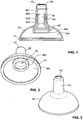
- FIGS. 1 to 5 is a preferred embodiment of the inventive teat shown.
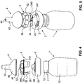
- FIGS. 4 and 5 show a liquid container, here a baby milk bottle 1, with a neck 11 with an external thread 12.
- a liquid container here a baby milk bottle 1
- a neck 11 with an external thread 12 On the baby milk bottle 1 can be a teat 4 by means of a mounting or receiving unit 2, 3 attach.
- the receiving unit 2, 3 consists essentially of two parts: a base part 2 and a receiving head 3.
- the base part 2 is preferably made of polypropylene (PP) or a polyamide, the receiving head 3 of a combination of PP or a polyamide with silicone, rubber or TPE.
- PP polypropylene
- the receiving head 3 of a combination of PP or a polyamide with silicone, rubber or TPE.
- silicone a silicone-based plastic, rubber or TPE is used.
- the base part 2 is dimensionally stable. It consists essentially of an annular body 20 and a truncated cone 25 integrally formed thereon. Centrally in the truncated cone 25, there is a passage opening or outflow opening 24 as the inlet opening of the unit. which the container interior of the container 1 to the outside, ie the teat, connects.
- the truncated cone 25 projects beyond the annular body 20 and extends upwards towards the receiving head 3.
- the outflow opening 24 is preferably arranged in the uppermost region, preferably in the flattened tip.
- This base part 2 can be placed on the container neck 11, but without it already fixed in position relative to it, in particular against rotation.
- the stop may be, for example, an inner bearing surface in the upper region of the base ring 2.
- Other types of stops, such as protruding noses or ribs, are also possible.
- the receiving head 3 is also annular and preferably rotationally symmetrical.
- the recording head 3 consists essentially of two areas.
- the lower, preferably hard area is formed here by a plurality of plug-in elements 30, which form uniformly distributed over the circumference portions of a common shell.
- the plug-in elements 30 form on their inside a common internal thread 301. Instead of an internal thread and an external thread may be present if the drinking container 1 is provided with a corresponding internal thread.
- the plug-in elements 30 can be plugged into slots 21 of the base part 2. Locking ribs 33 on the base part and on the receiving head 3 prevent the receiving head 3 from falling out of the base part 2.
- the upper portion of the pickup head 3 may be made of the same or a softer material than the lower one. It can be arbitrarily shaped in the peripheral area. Preferably, it has peripheral support bodies or structures, in this case support wings 340, which interact with the suction body or teat 4 described below.
- the teat 4 is in the FIGS. 1 to 3 good to see. He is integrally trained.
- the base body 40 has a frustoconical, dome-shaped or hemispherical base body 40 and a mouthpiece 42 formed integrally thereon.
- the mouthpiece 42 is tapered in its outer periphery relative to the base body 40, and this is widened in relation to the mouthpiece in its outer periphery.
- the base body 40 is preferably bent inwards with its lower edge, so that a radially inwardly directed flange 41 is formed.
- This flange 41 can, as shown here, be aligned with the plane defined by the lower opening of the base body. However, it may also be directed at an angle downwardly out of the opening of the body 40.
- the flange 41 is preferably formed relatively narrow and stiffened the lower portion of the body 40 is not or only slightly.
- the mouthpiece 42 is preferably formed in a known manner as a hollow cylinder or preferably as a truncated cone. It forms a thin-walled hollow body with a suction opening 43. It is bendable and / or flexibly deformable. In the mouthpiece 42, preferably in the uppermost tip, the suction opening 43 is present. From this occurs in use sucked out of the container 1 liquid.
- a suction channel 48 also called liquid or milk channel, extends inside the suction nipple 4 and opens at one end into the suction opening 43. With its second end, it protrudes into the base body 40 and forms the inlet opening of the teat 4.
- the mouthpiece 42 is double-walled over part of its length.
- the upper region of the mouthpiece 42 which is adjacent to the suction opening is of single-walled construction and preferably has a flange 430 projecting radially inwardly into the suction opening 43.
- the lower, the base body 40 directed towards area is double-walled.
- the double walling preferably begins at a taper 420 of the inner cross section of the mouthpiece 42.
- the inner circumferential and fully closed wall forms a tube 481. It extends at a distance from the outer wall 422 of the mouthpiece 42.
- the suction channel 48 extends inside this tube 481.
- 481 may radial or axial ribs, Pimples or other structures protrude. These structures may be arranged on the inside of the outer wall 422 and / or on the outside of the inner wall 481.
- the outer wall 422 of the mouthpiece 42 is preferably truncated or conically shaped. At least this should apply to its internal scope.
- the outer circumference of the tube 481 is preferably cylindrical.
- the inner wall 481 may be formed as flexible as the outer wall 420. Preferably, however, it is stiffer. However, it is still preferably flexible and not rigid or stiff.
- the lower region of the tube 481 protrudes into the main body 40. Its cross-section is widened, with its shape preferably following the shape of the transition region between mouthpiece 42 and base body 40. He also runs here, however, spaced from the walls.
- the lower portion of the tube 481 is formed by a circumferential skirt 46. This apron 46 protrudes to the recording head 3. On the skirt 46, an inwardly or outwardly projecting flange 460 is preferably formed.
- the suction channel 48 extends in a chamber or cavity 421 which is present in the interior of the mouthpiece 42 and adjoins the taper 420. It has a larger cross section than the taper 420. Preferably, this cavity as well as the suction opening has a substantially round cross section. Since the mouthpiece 42 is formed relatively soft, the mouthpiece 42, in particular the chamber 421 and the suction port 43 is deformed in the intended use. They preferably take an oval shape. The cavity 421 can also be longer but narrower. This shape may change during the sucking process according to the baby.
- the mouthpiece is preferably flexible over its entire length. Preferably, in the intended use, no parts projecting the mouthpiece over a substantial part of its length project into it, so that it remains deformable.
- the suction port 43 is connected in the mounted state via the cavity 421, the tube 481 and then via the passage opening 32 and the flow opening 24 with the interior of the container 1, so that the baby through this opening his drink, e.g. Tea, water or milk, you can drink.
- his drink e.g. Tea, water or milk
- the suction nipple 4 with its base 40 can be put over the receiving head 3.
- the base body 40 is everted according to the invention until it has received its first folded appearance and thus its second stable position.
- the mouthpiece 42 is not everted. This everting can be done by hand by the lower edge of the body 40 is taken and bent upwards and outwards.
- the base body 40 takes on its own from its second stable position, as in FIG. 8 is shown. Like in this one FIG. 8 is clearly visible, is in this stable inverted position, the first connection or fastening means, namely the lower end of the suction channel 48 free and surmounted the inverted base body 40.
- the teat 4 can be gripped by hand on the now outwardly projecting inner surface 400 of the body 40 be, and the free end of the tube 481, here the skirt 46, can be slipped over the truncated cone 35 and thus the passage opening 32 of the receiving head 3.
- the flange 460 of the skirt 46 engages behind a bead or a rib of the truncated cone 35 and is there sealingly. Since the skirt 46 is easily visible and easily accessible, this can be done in a simple manner.
- the main body 40 is now folded back into its stable position of use, in turn, only the free edge of the body 40 is pulled down.
- the flange 41 of the base body 40 engages behind the projecting edge between the upper and lower regions of the receiving head 3 and lies flat and sealing against the outer sealing surface 310 of the receiving head 3.
- the suction nipple 4 is now mounted on the receiving head 3, as in FIG. 3 is shown.
- the suction nipple 4 can thus be attached to the receiving head 3 or partially put over him. Subsequently, the recording head 3 can be inserted into the base part 2. The recording head 3 can be stuck in the base part 2, if this is free, but also if it is already on the container neck 1. Since the base part 2 in the axial direction with respect to the receiving head 2 can still move easily, the teat 4 can optionally be slipped over the former only when plugged recording head 3 / base part 2.
- the base part 2 or the receiving head 3 By turning the base part 2 or the receiving head 3 on the container neck 11, the two threads, external thread 12 and internal thread 301 engage in one another.
- the recording head 3 runs down the thread along. With him the base part is pulled down to its lower stop.
- Base part 2 and receiving head 3 are now mounted on the container 1 and secured against rotation relative to each other.
- the outer sealing surface 270 of the base part 2 is now pressed relative to the outer sealing surface 310 of the receiving head 3. They clamp the flange 41 of the suction nipple 4 and thus ensure a fluid and airtight connection between the nipple 4, receiving head 3 and base part 2.
- a differently shaped lower edge 41 of the teat 4 between the two parts 2, 3 are clamped sealing.
- the teat can be mounted in a simple manner despite relatively complicated internal structure.
- the teat still has a third stable position and thus a second everted appearance.
- the tube 481 can be pulled out of the mouthpiece 42.
- the mouthpiece 42 can thus also be everted into a stable position.
- the teat forms a shape in which the base body 40 is slipped in the direction of the mouthpiece 42 and the suction channel 48 is pulled out of the mouthpiece 42. This is in FIG. 9 shown.
- the base body 40 encloses the mouthpiece practically from the upper end of the suction channel 48, ie from the taper 480.
- the suction nipple everted in this way can be cleaned very well. Preferably, it is also produced in this everted position.
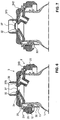
- FIGS. 6 and 7 a further receiving unit for receiving the inventive teat 4 is shown.
- the connection of the individual parts of the receiving unit is similar or the same as in the previous example.
- a self-contained valve membrane 37 is formed on the recording head 3. It covers the outflow opening 24 of the base part 2. In its peripheral region, which no longer covers the outflow opening 24, the valve membrane 37 has a small opening, the passage opening 32. This through hole 32 is located above the inner surface 241 of the base ring 2.
- the valve diaphragm 37 is preferably integrally formed on the receiving head 3. Either she herself is made of a soft material and the remaining head 3 is made of a hard material. However, for example, it may also be integrally formed together with soft support structures, here supporting cushions 340 ', and adhered to the hard part of the receiving head 3, welded to it or sprayed onto it.
- valve membrane 37 is surrounded by an upstanding and circumferential collar 39, which may also be formed of hard or soft material integral with the rest of the receiving head 3.
- This collar 39 preferably has circumferential outer ribs, which are not shown here.
- the valve membrane 37 forms a check valve, which is connected via a ring joint or hinge 370 with the remaining receiving head 3.
- the outside of this ring joint 370 arranged through hole 32 forms a flow restrictor.
- This flow restrictor 32 has a smaller cross-sectional area than the subsequent areas through which the liquid flows.
- the milk or central channel 48 and the suction opening 43 have a larger cross-sectional area.
- the suction channel 48 may have one or more constrictions spaced from the suction opening 43.
- the passage opening 32 and the check valve 37 is arranged outside the mouthpiece 42.
- the suction opening 43 and, in a preferred embodiment, the milk channel 48 has a cross-sectional area which is a multiple of the cross-sectional area of the passage opening 32.
- the cross-sectional area of the suction opening 43 is more than 10 times, in particular more than 50 times, and preferably more than 100 times larger than that of the passage opening 32.
- the entire region of the suction channel 48 extending in the mouthpiece 42 has one indicated above Factors larger cross-sectional area. Typical diameters of the suction opening 43 are 7 mm and the passage opening is 0.25 to 0.7 mm.
- both the flow restrictor and the check valve are present.
- no check valve is present, but only the flow restrictor forming passage opening 32.
- This may be centrally or centrally located in the head part 3.
- a plurality of through-openings may be present as long as they together have a cross-sectional area for the flow of the liquid, this area being smaller than the cross-sectional area of the suction opening 43.
- the through-opening serving as a flow restrictor may also be arranged in the base part 2.
- a plurality of passage openings can be distributed over the peripheral circumference of the membrane.
- the area around the at least one passage opening may also be formed of hard material and the soft part of the membrane may be formed adjacent thereto.
- a differently shaped teat unit with the inventive arrangement of large suction opening and recessed passage opening be present.
- the liquid container may be provided with the outflow opening 24, which is closed by the membrane.
- the outflow opening 24 may be selected to be so small that it itself forms the passage opening and thus the flow restrictor.
- the teat 4 may be attached in other ways.
- the skirt 46 may be inserted into the collar 39.
- the inventive nipple can be connected to the feeding bottle in a simple and hygienic manner, is easy to clean and allows the most lifelike sucking possible.
Description
Die Erfindung betrifft einen Saugnippel gemäss Oberbegriff des Patentanspruchs 1 sowie eine Saugnippeleinheit gemäss Oberbegriff des Patentanspruchs 12 bzw. 13.The invention relates to a teat according to the preamble of patent claim 1 and a teat unit according to the preamble of
Im Stand der Technik sind die unterschiedlichsten Saugnippel für Babyflaschen bekannt. Saugnippel sollten einfach zu befestigen und gut zu reinigen sein. Des Weiteren sollten sie dem Säugling ein möglichst der Natur nachempfundenes Saugen ermöglichen, so dass er ohne Saugverwirrung zwischen Mutterbrust und Saugflasche hin und her wechseln kann.In the prior art, the most diverse teat for baby bottles are known. Teat nipples should be easy to attach and easy to clean. Furthermore, they should allow the infant to a possibly nature-inspired sucking, so that he can switch back and forth between the mother's breast and feeding bottle without Sauggefirrung.
Die meisten der bekannten Saugnippel konzentrieren sich auf die optimale Lösung einer der oben genannten Aufgaben. Viele dieser Saugnippel sind jedoch kompliziert aufgebaut und auch relativ kostenintensiv in ihrer Herstellung.Most of the known teat nipples focus on the optimal solution to one of the above tasks. However, many of these teat nipples are complicated in structure and also relatively expensive to manufacture.
Es ist deshalb eine Aufgabe der Erfindung, einen optimierten Saugnippel und eine optimierte Saugnippeleinheit zu schaffen.It is therefore an object of the invention to provide an optimized teat and an optimized teat unit.
Diese Aufgabe lösten ein Saugnippel und eine Saugnippeleinheit mit den Merkmalen der Patentansprüche 1, 12 und 13.This object was achieved by a teat and a teat unit with the features of
Der erfindungsgemässe Saugnippel zur Verbindung mit einer Aufnahmeeinheit eines Getränkebehälters weist einen Grundkörper und ein an den Grundkörper anschliessendes, gegenüber dem Grundkörper verjüngtes Mundstück mit mindestens einer Saugöffnung, durch welche die Flüssigkeit aus dem Saugnippel nach aussen austritt, und einem freien Ende auf. Der Saugnippel weist ein erstes Verbindungselement zur Verbindung mit der Aufnahmeeinheit und ein zweites Verbindungselement zur Verbindung mit der Aufnahmeeinheit sowie einen Saugkanal auf. Der Saugkanal verläuft im Mundstück. Er mündet mit einem ersten Ende in die Saugöffnung und ist mit einem zweiten Ende zum Grundkörper hin gerichtet. Dieses zweite Ende bildet das erste Verbindungselement zur dichtenden Verbindung mit der Aufnahmeeinheit. Erfindungsgemäss ist der Grundkörper zum freien Ende des Mundstücks hin umklappbar ausgestaltet ist und der Saugnippel ist ferner an mindestens einer zweiten Stelle umklappbar ausgestaltet.The inventive suction nipple for connection to a receiving unit of a beverage container has a main body and an adjoining the main body, tapered relative to the main body mouthpiece with at least one suction port through which the liquid exits the teat to the outside, and a free end. The teat has a first connecting element for connection to the receiving unit and a second connecting element for connection to the receiving unit and a suction channel. The suction channel runs in the mouthpiece. It opens with a first end in the suction opening and is directed with a second end to the base body. This second end forms the first connection element for sealing connection with the receiving unit. According to the invention, the main body is designed to be foldable towards the free end of the mouthpiece, and the teat is further designed to be foldable at at least one second location.
Der Saugnippel weist einen stabilen Grundzustand, einen ersten stabilen umgeklappten Zustand und mindestens einen zweiten stabilen umgeklappten Zustand auf, wobei der mindestens zweite stabile Zustand sich in der äusseren Erscheinungsform vom ersten stabilen Zustand und vom Grundzustand unterscheidet.The teat has a stable ground state, a first stable folded state and at least a second stable folded state, wherein the at least second stable state differs in the external appearance from the first stable state and the ground state.
Vorzugsweise weist das Mundstück zwei Abschnitte auf, wobei das Mundstück im Übergangsbereich zwischen diesen zwei Abschnitten umklappbar ausgestaltet ist.Preferably, the mouthpiece has two sections, wherein the mouthpiece is designed such that it can be folded over in the transition area between these two sections.
Vorzugsweise ist das Mundstück in einem Bereich zwischen seinem freien Ende und seinem Übergang zum Grundkörper umklappbar ausgestaltet.Preferably, the mouthpiece in a region between its free end and its transition to the main body designed umklappbar.
In einer bevorzugten Ausführungsform verläuft der Saugkanal mindestens teilweise in einer Röhre, welche mindestens teilweise im Innern des Mundstücks und beabstandet zu einer Innenseite des Mundstücks verläuft. Die Röhre weist ein erstes Röhrenende auf, welches mit dem Mundstück verbunden ist. Ein zweites freies Röhrenende bildet das zweite Ende des Saugkanals. Erfindungsgemäss endet das erste Röhrenende beabstandet zum freien Ende des Mundstücks im Innern des Mundstücks.In a preferred embodiment, the suction channel extends at least partially in a tube which extends at least partially inside the mouthpiece and spaced from an inside of the mouthpiece. The tube has a first tube end connected to the mouthpiece. A second free tube end forms the second end of the suction channel. According to the invention, the first end of the tube ends at a distance from the free end of the mouthpiece inside the mouthpiece.
Vorzugsweise befindet sich die Saugöffnung im freien Ende des Mundstücks, d.h. in seiner vordersten Spitze und besteht aus einem einzigen Loch. Die Saugöffnung kann auch im vorderen Bereich des Mundstücks nicht in der Spitze, sondern seitlich angeordnet sein. Sie kann zudem in beiden Varianten durch mehrere Löcher gebildet sein.Preferably, the suction opening is in the free end of the mouthpiece, i. in its foremost tip and consists of a single hole. The suction opening can also be arranged not laterally in the tip, but laterally in the front region of the mouthpiece. It can also be formed in both variants by several holes.
Dieser Saugnippel weist mehrere Vorteile auf. Er trennt die Funktionen "dichten" und "befestigen". Das erste Verbindungsmittel dichtet die Verbindung des Saugkanals mit der Aufnahmeeinheit und somit mit dem Innenraum des Getränkebehälters gegen den restlichen Saugnippel und somit gegen aussen ab. Der Saugnippel selber ist aber vor allem durch das zweite Verbindungsmittel, vorzugsweise einem umlaufenden Flansch des Grundkörpers, mit der Aufnahmeeinheit verbunden. Diese Verbindung unterliegt Normen, welche erfüllt sein müssen. Der Saugnippel darf sich nicht bei erhöhtem oder schräg angelegtem Zug durch den Säugling während des Saugens vom Getränkebehälter lösen.This teat has several advantages. It separates the functions "dense" and "fasten". The first connecting means seals the connection of the suction channel with the receiving unit and thus with the interior of the beverage container against the remaining teat and thus against the outside. The teat itself is but mainly by the second connecting means, preferably a circumferential flange of the body, connected to the receiving unit. This connection is subject to standards that must be met. The nipple should not come off the beverage container during suckling when the baby is sucking or pulling on it.
Da der Grundkörper in der ersten Erscheinungsform umgeklappt bzw. umgestülpt ist, ist das erste Verbindungselement besser zugänglich. Es kann so einfacher mit der Aufnahmeeinheit verbunden werden.Since the main body is folded down or everted in the first appearance, the first connecting element is more accessible. It is easier to connect to the recording unit.
Ist der Zwischenraum zwischen Mundstück und Röhre sich gegenüber dem Mundstück erweiternd ausgebildet, so lässt sich die Röhre vom zweiten umgestülpten Zustand relativ einfach wieder in das Mundstück hinein schieben und so die normale Gebrauchslage wieder herstellen. Dies lässt sich beispielsweise erreichen, indem das Mundstück mindestens über den von der Röhre durchsetzten Bereich konisch ausgebildet und/oder die Röhre in diesem Bereich hohlzylinderförmig ausgebildet ist.If the intermediate space between the mouthpiece and the tube is widening in relation to the mouthpiece, then the tube can relatively easily be pushed back into the mouthpiece from the second everted state and thus restore the normal position of use. This can be achieved, for example, by designing the mouthpiece to be conical at least over the area penetrated by the tube and / or to make the tube hollow-cylindrical in this area.
Ein weiterer Vorteil ist, dass der einfach und insbesondere der zweifach umgeklappte Saugnippel besser gereinigt werden kann, da allfällige komplexe Strukturen im Innern des Grundkörpers, wie beispielsweise das erste Verbindungselement, frei liegen und zwecks Reinigung besser zugänglich sind.Another advantage is that the simple and in particular the double-folded teat can be better cleaned because any complex structures in the interior of the body, such as the first connecting element, are exposed and are more accessible for the purpose of cleaning.
Der Saugnippel lässt sich beispielsweise auch im einfach und insbesondere im zweifach umgeklappten Zustand einstückig herstellen. Dies erleichtert einerseits die Herstellung und senkt die Herstellungskosten. Des Weiteren kann der innere Bereich des Saugnippels, insbesondere der Zwischenraum zwischen Röhre und Mundstück, einfacher mit radialen oder axialen Rippen, Dellen, Noppen oder anderen Innenstrukturen versehen werden.The suction nipple can be produced in one piece, for example, even in a simple and in particular in a doubly folded state. This facilitates on the one hand the production and lowers the production costs. Furthermore, the inner region of the teat, in particular the space between the tube and mouthpiece, can be provided more easily with radial or axial ribs, dents, nubs or other internal structures.
Vorzugsweise ist das Mundstück in einem oberen, der Saugöffnung benachbarten Bereich einwandig und in einem unteren, dem Grundkörper benachbarten Bereich doppelwandig ausgeführt.Preferably, the mouthpiece in a top, the suction opening adjacent region is single-walled and executed in a lower, the base body adjacent region double-walled.
Im umgeklappten Zustand des Grundkörpers liegen Flächen zur Berührung frei, welche bei bestimmungsgemässen Gebrauch des Saugnippels nicht in Kontakt mit einer durch den Saugnippel fliessenden Flüssigkeit stehen, wobei der Saugnippel alleine durch Halten an diesen Flächen mit der Aufnahmeeinheit bestimmungsgemäss verbindbar ist. Der Saugnippel ist ohne zusätzliche Hilfsmittel oder Werkzeuge mit der Aufnahmeeinheit verbindbar bzw. auf dieser montierbar.In the folded state of the body surfaces are exposed to the touch, which are not in contact with a liquid flowing through the teat under normal use of the teat, wherein the teat is connected by holding these surfaces with the receiving unit as intended. The teat is connectable without additional tools or tools with the receiving unit or mounted on this.
Dies ist ein weiterer Vorteil, da der Saugnippel ausschliesslich an Stellen angefasst werden kann, welche später im bestimmungsgemässen Gebrauch weder in den Mund des Babys gelangen, noch von der Milch oder der zu trinkenden Flüssigkeit kontaktiert werden. Dadurch ist gewährleistet, dass auch die Montage des Saugnippels unter Berücksichtigung hoher Hygienestandards erfolgen kann. Gerade bei Frühgeborenen und Neugeborenen ist dies sehr wichtig.This is a further advantage, since the teat can only be touched in places which later, in the intended use, neither reach the baby's mouth nor are contacted by the milk or the liquid to be drunk. This ensures that the assembly of the suction nipple can take place in consideration of high hygiene standards. Especially in premature babies and newborns, this is very important.
Der umgeklappte Grundkörper lässt sich auf seiner Innenseite anfassen und das Mundstück muss zu keinem Zeitpunkt berührt werden. Da im Innern des Grundkörpers der röhrenförmige Saugkanal vorhanden ist, kommt auch die Innenseite des Grundkörpers nicht in Kontakt mit der zu trinkenden Flüssigkeit.The folded body can be touched on its inside and the mouthpiece must not be touched at any time. Since inside the main body of the tubular suction channel is present, and the inside of the body does not come into contact with the liquid to be drunk.
Vorzugsweise verläuft der Saugkanal zwischen dem ersten Röhrenende und der Saugöffnung in einer Kammer im Innern des Mundstücks. Diese Kammer ändert während des Saugvorgangs ihre Form und passt sich ähnlich dem natürlichen Nippel der Mutterbrust dem Saugprozess und dem Mund des Babys an.Preferably, the suction channel extends between the first tube end and the suction opening in a chamber in the interior of the mouthpiece. This chamber changes its shape during suction and adapts to the baby's sucking process and mouth similar to the natural nipple of the mother's breast.
Vorzugsweise sind das Mundstück und die Röhre mindestens im Bereich der Kammer biegeweich ausgebildet, um sich dem Saugvorgang optimal und möglichst naturgetreu anzupassen.Preferably, the mouthpiece and the tube are bendable at least in the region of the chamber, in order to adapt to the suction optimally and as lifelike as possible.
Dieser Saugnippel erlaubt eine möglichst naturgetreue Nachbildung, so dass Saugverwirrung beim Wechseln vom Saugnippel auf die natürliche Mutterbrust vermieden werden kann.This nipple allows a lifelike replica, so that Saugverwirrung can be avoided when changing from teat to the natural mother's breast.
Im Zwischenraum zwischen Röhre und Mundstück können Distanzhalter in Form von radialen oder axialen Rippen, Noppen, Dellen oder anderen Oberflächenstrukturen angeordnet sein, welche verhindern, dass die Wände der Röhre und des Mundstücks während des Saugvorgangs aneinander haften oder kleben bleiben.In the space between the tube and mouthpiece, spacers may be arranged in the form of radial or axial ribs, nubs, dimples or other surface structures which prevent the walls of the tube and mouthpiece from sticking or sticking together during the suction process.
Der erfindungsgemässe Saugnippel lässt sich in einer Saugnippeleinheit zum Saugen einer Flüssigkeit aus einem Flüssigkeitsbehälter einsetzen. Diese Saugnippeleinheit weist den Saugnippel und einen Durchflussbegrenzer mit einer Durchgangsöffnung auf. Der Saugnippel weist ein Mundstück und einen am Mundstück angeformten, sich gegenüber dem Mundstück erweiternden Grundkörper auf, wobei im Mundstück eine Saugöffnung vorhanden ist. Der Durchflussbegrenzer bestimmt einen maximalen Durchfluss der vom Flüssigkeitsbehälter durch die Saugöffnung fliessenden Flüssigkeit. Erfindungsgemäss ist der Durchflussbegrenzer ausserhalb des Mundstücks angeordnet. Die Saugöffnung weist eine grössere Querschnittsfläche auf als die Durchgangsöffnung des Durchflussbegrenzers.The inventive teat can be used in a teat unit for sucking a liquid from a liquid container. This Saugnippeleinheit has the teat and a flow restrictor with a through hole. The teat has a mouthpiece and an integrally formed on the mouthpiece, extending towards the mouthpiece body, wherein in the mouthpiece a suction opening is present. The flow restrictor determines a maximum flow of liquid flowing from the liquid container through the suction opening. According to the invention, the flow restrictor is arranged outside the mouthpiece. The suction opening has a larger cross-sectional area than the passage opening of the flow restrictor.
Diese Saugnippeleinheit erlaubt ein möglichst naturgetreues Saugen. Dank der grossen Öffnung lässt sich das Mundstück, auch Nippel genannt, während des Saugvorgangs gut verformen, und es passt sich optimal den Mund- und Zungenbewegungen des Säuglings an. Der Säugling erhält im Mund ein ähnliches Gefühl wie wenn er an einem natürlichen Nippel einer Mutterbrust saugen würde. Das Mundstück ist biegeweich ausgebildet, und im bestimmungsgemässen Gebrauch ragen vorzugsweise keine das Mundstück über einen wesentlichen Teil seiner Länge versteifende Teile in dieses hinein. Im bestimmungsgemässen Gebrauch ist das Mundstück deshalb vorzugsweise deformierbar ausgebildet.This teat unit allows a lifelike sucking. Thanks to the large opening, the mouthpiece, also called nipple, can be deformed well during the suction process, and it optimally adapts to the movements of the baby's mouth and tongue. The infant gets a similar sensation in the mouth as if it were sucking on a natural nipple of a mother's breast. The mouthpiece is designed to be bendable, and in intended use, preferably no parts which stiffen the mouthpiece over a substantial part of its length project into it. In the intended use, the mouthpiece is therefore preferably deformable.
Typische Durchmesser für eine runde Saugöffnung betragen 3 bis 8 mm und für einen runden Durchflussbegrenzer 0.2.bis 0.7 mm.Typical diameters for a round suction opening are 3 to 8 mm and for a round flow limiter 0.2 to 0.7 mm.
Der Durchflussbegrenzer ist jedoch ausserhalb des Mundstücks angeordnet, d.h. ausserhalb desjenigen Teils, welches im bestimmungsgemässen Gebrauch vom Säugling in den Mund genommen wird. Dadurch kann der Säugling durch mechanischen Druck oder Zug, verursacht durch seine Lippen- und Mundbewegungen, den Durchflussbegrenzer nicht beeinflussen.However, the flow restrictor is located outside the mouthpiece, i. outside of that part which is put into the mouth by the infant in the intended use. As a result, the infant can not influence the flow restrictor by mechanical pressure or tension caused by his lip and mouth movements.
Die erfindungsgemässe Saugnippeleinheit trennt somit die Funktionen:
- möglichst naturgetreues Anpassen und Verformen des Mundstücks und
- Begrenzen des Durchflusses, damit sich der Säugling nicht verschluckt.
- Lifelike adaptation and deformation of the mouthpiece and
- Limit the flow so that the baby does not swallow.
Der erfindungsgemässe Saugnippel lässt sich ferner in einer Saugnippeleinheit zum Saugen einer Flüssigkeit aus einem Flüssigkeitsbehälter verwenden, welche den Saugnippel und einen Durchflussbegrenzer mit einer Durchgangsöffnung aufweist. Der Saugnippel weist ein Mundstück und einen am Mundstück angeformten, sich gegenüber dem Mundstück erweiternden Grundkörper auf, wobei im Mundstück eine Saugöffnung vorhanden ist. Der Durchflussbegrenzer bestimmt einen maximalen Durchfluss der vom Flüssigkeitsbehälter durch die Saugöffnung fliessenden Flüssigkeit. Erfindungsgemäss ist der Durchflussbegrenzer ausserhalb des Mundstücks angeordnet und die Saugnippeleinheit weist ein Einwegventil auf, welches ausserhalb des Mundstücks angeordnet ist, und wobei der Durchflussbegrenzer im Einwegventil oder in einem benachbarten Bereich dazu angeordnet ist.The teat according to the invention can also be used in a teat unit for sucking a liquid from a liquid container which has the teat and a flow restrictor with a passage opening. The teat has a mouthpiece and an integrally formed on the mouthpiece, extending towards the mouthpiece body, wherein in the mouthpiece a suction opening is present. The flow restrictor determines a maximum flow of liquid flowing from the liquid container through the suction opening. According to the invention, the flow restrictor is arranged outside the mouthpiece and the teat unit is arranged has a one-way valve which is located outside the mouthpiece, and wherein the flow restrictor is disposed in the one-way valve or in an adjacent region thereto.
Diese Saugnippeleinheit ermöglicht ein möglichst naturgetreues Saugen, da in der Saugeinheit nur Atmosphärendruck oder Unterdruck vorliegt. Es entsteht kein Überdruck. Die Milch spritzt somit nicht in den Mund des Säuglings, sondern fliesst entsprechend dem vom Säugling angelegten Vakuum in dessen Mund. Der Milchfluss erfolgt dabei annähernd proportional zu dem vom Säugling angelegten Vakuum.This Saugnippeleinheit allows lifelike as possible, since in the suction unit only atmospheric pressure or negative pressure is present. There is no overpressure. The milk thus does not splash into the baby's mouth, but flows into the mouth according to the vacuum applied by the baby. The milk flow is approximately proportional to the vacuum applied by the infant.
Diese Saugnippeleinheit ermöglicht ein Saugen, welches rein vakuumgesteuert ist und von der übrigen, insbesondere der peristaltischen Bewegung der Zunge weitgehend unabhängig erfolgt. Bewegt sich der hintere Bereich der Zunge zum oberen Gaumen hin, so soll keine Milch fliessen. Bewegt sich dieser hintere Bereich vom oberen Gaumen weg, so fliesst die Milch.This Saugnippeleinheit allows a suction, which is purely vacuum-controlled and largely independent of the rest, in particular the peristaltic movement of the tongue. If the posterior region of the tongue moves towards the upper palate, no milk should flow. If this rear area moves away from the upper palate, the milk flows.
Diese Saugnippeleinheit berücksichtigt die Erkenntnis, dass das Baby beim Saugen nicht zwischen Vakuum und Atmosphärendruck hin und her wechselt. Es behält vielmehr während des ganzen Saugvorgangs ein Basisvakuum bei. Im Gegensatz zu den Anordnungen gemäss dem Stand der Technik schliesst nun das Ventil bei Erreichen dieses Basisvakuums. Steigt der Absolutwert des angelegten Vakuums über dieses Basisvakuum, so öffnet das Ventil und die Milch oder Flüssigkeit kann fliessen. Das Baby kann somit trotz Beibehaltung des Basisvakuums eine Pause einlegen, Luft holen oder sich erholen und neue Kraft sammeln, wie dies auch an der Mutterbrust geschieht. Vorzugsweise öffnet die erfindungsgemässe Vorrichtung bereits bei einem kleinen Unterdruck von 1 bis 90 mmHg, vorzugsweise 20 bis 70 mmHg. Noch bevorzugtere Werte liegen zwischen 20 bis 30 mmHg bzw. 5 bis 30 mmHg. Diese Werte liegen in ihrem Absolutbetrag knapp oberhalb einem typischen Basisvakuum eines Babys.This teat unit takes into account the fact that the baby does not switch back and forth between vacuum and atmospheric pressure when sucking. It rather maintains a base vacuum throughout the suction process. In contrast to the arrangements according to the prior art now closes the valve upon reaching this base vacuum. If the absolute value of the applied vacuum rises above this basic vacuum, the valve opens and the milk or liquid can flow. The baby is thus able to take a break despite being able to maintain the basic vacuum, to take a breath or to recover, and to gather new strength, as happens with the mother's breast. Preferably, the device according to the invention opens even at a low negative pressure of 1 to 90 mmHg, preferably 20 to 70 mmHg. Even more preferred values are between 20 to 30 mmHg and 5 to 30 mmHg. These values are in their absolute value just above a typical base vacuum of a baby.
Das Ventil hat jedoch während des Saugvorgangs keinen weiteren Einfluss auf den Milchfluss. Der Öffnungsgrad und die Funktionsweise des Ventils beeinflussen den Milchfluss durch die Saugöffnung nicht.However, the valve has no further influence on the milk flow during the suction process. The degree of opening and operation of the valve does not affect the flow of milk through the suction port.
Da das Rückschlagventil und der Durchflussbegrenzer ausserhalb des Mundstücks angeordnet sind, beeinflusst eine allfällige Verformung des Mundstücks die Funktionsweise des Rückschlagventils nicht. Das Baby kann somit durch mechanischen Druck und/oder Zug keinen Einfluss auf das Rückschlagventil ausüben.Since the check valve and the flow restrictor are located outside the mouthpiece, a possible deformation of the mouthpiece does not affect the operation of the check valve. The baby can thus exert no influence on the check valve by mechanical pressure and / or train.
In einer ersten Ausführungsform überdeckt das Rückschlagventil die Durchgangsöffnung des Durchflussbegrenzers. In einer bevorzugten Ausführungsform überdeckt das Rückschlagventil jedoch nicht die relativ kleine Durchgangsöffnung des Durchflussbegrenzers sondern eine grössere Öffnung. Diese Öffnung ist vorzugsweise in Fliessrichtung der Flüssigkeit vor dem Durchflussbegrenzer angeordnet, d.h. also zum Flüssigkeitsbehälter hin gerichtet. Sie kann jedoch auch in Fliessrichtung nachfolgend dem Durchflussbegrenzer angeordnet sein.In a first embodiment, the check valve covers the passage opening of the flow restrictor. In a preferred embodiment, however, the check valve does not cover the relatively small passage opening of the flow restrictor but a larger opening. This opening is preferably arranged in the flow direction of the liquid in front of the flow restrictor, i. So directed to the liquid container. However, it can also be arranged downstream of the flow restrictor in the direction of flow.
In anderen Ausführungsformen befindet sich die Öffnung des Durchflussbegrenzers im steif ausgebildeten Ventilsitz, d.h. hier im Basisteil. Dabei kann diese Öffnung von der Ventilmembran überdeckt und geschlossen werden. Sie kann jedoch auch benachbart angeordnet sein und in das Totvolumen führen.In other embodiments, the opening of the flow restrictor is in the rigidly formed valve seat, i. here in the base part. In this case, this opening can be covered and closed by the valve membrane. However, it can also be arranged adjacent and lead into the dead volume.
In einer weiteren Ausführungsform kann die Öffnung des Durchflussbegrenzers in der Ventilmembran angeordnet sein und durch dichtende Auflage der Membran auf den Ventilsitz geschlossen werden. In diesem Fall ist die Ausflussöffnung benachbart dazu im Ventilsitz angeordnet und wird von der Membran nicht geschlossen, sondern führt in das Totvolumen. Die Ausflussöffnung kann dabei gleich gross oder grösser ausgebildet sein als die Öffnung des Durchflussbegrenzers.In a further embodiment, the opening of the flow restrictor can be arranged in the valve membrane and closed by sealing support of the membrane on the valve seat. In this case, the outflow opening is arranged adjacent to the valve seat and is not closed by the membrane, but leads into the dead volume. The outflow opening can be made the same size or larger than the opening of the flow restrictor.
Der Durchflussbegrenzer kann somit im, über oder unterhalb der Ventilmembran angeordnet sein.The flow restrictor can thus be arranged in, above or below the valve membrane.
Da das Ventil und der Durchflussbegrenzer bzw. die Auslassöffnung und das Ventil benachbart zueinander angeordnet sind, ist das Totvolumen, in welchem ebenfalls ein Vakuum erzeugt werden muss, minimiert. Das Ventil bzw. der Sauger funktioniert auch bei geringen Durchflussmengen einwandfrei.Since the valve and the flow restrictor or the outlet opening and the valve are arranged adjacent to each other, the dead volume, in which also a vacuum must be generated, minimized. The valve or the sucker works too flawless at low flow rates.
Vorzugsweise ist das Ventil einfach zerlegbar und die Saugnippeleinheit deshalb einfach zu reinigen. Wird eine Membran verwendet, so lässt sich diese durch Klemmung zwischen Einzelteilen halten.Preferably, the valve is easy to disassemble and therefore easy to clean the teat unit. If a membrane is used, it can be held by clamping between individual parts.
Anstelle einer eingeklemmten Membran mit oder ohne wohldefiniertem Öffnungsquerschnitt lässt sich auch ein Schirmventil, ein Schnabelventil oder eine geschlitzte Membran verwenden.Instead of a clamped membrane with or without a well-defined opening cross-section, an umbrella valve, a beak valve or a slotted membrane can also be used.
Weitere vorteilhafte Ausführungsformen gehen aus den abhängigen Patentansprüchen hervor.Further advantageous embodiments will become apparent from the dependent claims.
Im Folgenden wird der Erfindungsgegenstand anhand eines bevorzugten Ausführungsbeispiels, welches in den beiliegenden Zeichnungen dargestellt ist, erläutert. Gleiche Teile sind mit gleichen Bezugszeichen versehen. Es zeigen:
- Figur 1
- einen Längsschnitt durch einen erfindungsgemässen Saugnippel;
Figur 2- eine perspektivische Ansicht des Saugnippels gemäss
Figur 1 von unten; Figur 3- eine perspektivische Ansicht des Saugnippels gemäss
Figur 1 von der Seite; Figur 4- eine Seitenansicht einer Babyflasche mit einer Aufnahmeeinheit und dem Saugnippel gemäss
Figur 1 ; - Figur 5
- eine Explosionsdarstellung der Einheit gemäss
Figur 4 ; - Figur 6
- einen Längsschnitt durch eine Aufnahmeeinheit zur Verbindung mit dem Saugnippel gemäss
Figur 1 mit geschlossenem Ventil; - Figur 7
- einen Längsschnitt durch die Aufnahmeeinheit gemäss
Figur 6 mit geöffnetem Ventil; - Figur 8
- einen Teilschnitt des Saugnippels gemäss
Figur 1 in einer ersten umgestülpten Erscheinungsform und - Figur 9
- einen Teilschnitt des Saugnippels gemäss
Figur 1 in einer zweiten umgestülpten Erscheinungsform.
- FIG. 1
- a longitudinal section through a teat according to the invention;
- FIG. 2
- a perspective view of the teat according to
FIG. 1 from underneath; - FIG. 3
- a perspective view of the teat according to
FIG. 1 of the page; - FIG. 4
- a side view of a baby bottle with a receiving unit and the teat according to
FIG. 1 ; - FIG. 5
- an exploded view of the unit according to
FIG. 4 ; - FIG. 6
- a longitudinal section through a receiving unit for connection to the teat according to
FIG. 1 with closed valve; - FIG. 7
- a longitudinal section through the receiving unit according to
FIG. 6 with open valve; - FIG. 8
- a partial section of the teat according to
FIG. 1 in a first inverted appearance and - FIG. 9
- a partial section of the teat according to
FIG. 1 in a second inverted appearance.
In den
Die
Die Aufnahmeeinheit 2, 3 besteht im Wesentlichen aus zwei Teilen: einem Basisteil 2 und einem Aufnahmekopf 3. Das Basisteil 2 besteht vorzugsweise aus Polypropylen (PP) oder einem Polyamid, der Aufnahmekopf 3 aus einer Kombination von PP oder einem Polyamid mit Silikon, Kautschuk oder TPE. Für den Saugnippel 4 wird vorzugsweise Silikon, ein Kunststoff auf Silikonbasis, Kautschuk oder TPE verwendet.The receiving
Das Basisteil 2 ist formstabil ausgebildet. Es besteht im Wesentlichen aus einem Ringkörper 20 und einem daran angeformten Kegelstumpf 25. Zentrisch im Kegelstumpf 25 ist als Eingangsöffnung der Einheit eine Durchgangs- oder Ausflussöffnung 24 vorhanden, welche den Behälterinnenraum des Behälters 1 nach aussen, d.h. zum Saugnippel hin, verbindet. Der Kegelstumpf 25 überragt den Ringkörper 20 und erstreckt sich nach oben zum Aufnahmekopf 3 hin. Die Ausflussöffnung 24 ist vorzugsweise im obersten Bereich, vorzugsweise in der abgeflachten Spitze, angeordnet.The
Dieses Basisteil 2 lässt sich auf den Behälterhals 11 aufsetzen, ohne dass es jedoch bereits relativ zu ihm lagefixiert, insbesondere verdrehgesichert ist. Dabei ist ein unterer Anschlag vorhanden, welcher begrenzt, wie weit der Behälterhals 11 das Basisteil 2 durchsetzen kann, d.h. wie weit das Basisteil 2 auf dem Behälterhals 11 nach unten rutschen kann. Der Anschlag kann beispielsweise eine innere Auflagefläche im oberen Bereich des Basisrings 2 sein. Andere Arten von Anschlägen, wie beispielsweise vorstehende Nasen oder Rippen sind auch möglich.This
Der Aufnahmekopf 3 ist ebenfalls ringförmig und vorzugsweise rotationssymmetrisch ausgebildet. Der Aufnahmekopf 3 besteht im Wesentlichen aus zwei Bereichen. Der untere, vorzugsweise harte Bereich wird hier durch mehrere Steckelemente 30 gebildet, welche gleichmässig über den Umfang verteilte Abschnitte eines gemeinsamen Mantels bilden. Die Steckelemente 30 bilden auf ihrer Innenseite ein gemeinsames Innengewinde 301. Anstelle eines Innengewindes kann auch ein Aussengewinde vorhanden sein, falls der Trinkbehälter 1 mit einem entsprechenden Innengewinde versehen ist.The receiving
Die Steckelemente 30 lassen sich in Schlitze 21 des Basisteils 2 einstecken. Einrastrippen 33 am Basisteil und am Aufnahmekopf 3 verhindern ein Herausfallen des Aufnahmekopfes 3 aus dem Basisteil 2.The plug-in
Der obere Bereich des Aufnahmekopfes 3 kann aus demselben oder einem weicheren Material als der untere gefertigt sein. Er kann im peripheren Bereich beliebig geformt sein. Vorzugsweise weist er periphere Stützkörper bzw. -strukturen, hier Stützflügel 340 auf, welche mit dem nachfolgend beschriebenen Saugkörper oder Saugnippel 4 zusammenwirken.The upper portion of the
Der Saugnippel 4 ist in den
Er weist einen kegelstumpfförmigen, kalotten- oder halbkugelförmigen Grundkörper 40 und ein daran einstückig angeformtes Mundstück 42 auf. Das Mundstück 42 ist in seinem äusseren Umfang gegenüber dem Grundkörper 40 verjüngt, bzw. dieser ist gegenüber dem Mundstück in seinem äusseren Umfang erweitert. Der Grundkörper 40 ist vorzugsweise mit seinem unteren Rand nach innen gebogen, so dass ein radial nach innen gerichteter Flansch 41 entsteht. Dieser Flansch 41 kann, wie hier dargestellt, mit der durch die untere Öffnung des Grundkörpers definierten Ebene fluchten. Er kann jedoch auch in einem Winkel nach unten aus der Öffnung des Grundkörpers 40 hinaus gerichtet sein. Der Flansch 41 ist vorzugsweise relativ schmal ausgebildet und versteift den unteren Bereich des Grundkörpers 40 nicht oder nur unwesentlich.It has a frustoconical, dome-shaped or
Das Mundstück 42 ist vorzugsweise in bekannter Weise hohlzylinderförmig oder vorzugsweise als Kegelstumpf ausgebildet. Es bildet einen dünnwandigen Hohlkörper mit einer Saugöffnung 43. Es ist biegeweich und/oder flexibel verformbar ausgebildet. Im Mundstück 42, vorzugsweise in der obersten Spitze, ist die Saugöffnung 43 vorhanden. Aus dieser tritt bei Gebrauch die aus dem Behälter 1 gesogene Flüssigkeit aus.The
Ein Saugkanal 48, auch Flüssigkeits- oder Milchkanal genannt, verläuft im Innern des Saugnippels 4 und mündet mit einem Ende in die Saugöffnung 43. Mit seinem zweiten Ende ragt er in den Grundkörper 40 hinein und bildet die Eingangsöffnung des Saugnippels 4.A
Das Mundstück 42 ist über einen Teil seiner Länge doppelwandig ausgeführt. Der obere, der Saugöffnung benachbarte Bereich des Mundstücks 42 ist einwandig ausgeführt und weist vorzugsweise einen in die Saugöffnung 43 radial nach innen ragenden Flansch 430 auf. Der untere, dem Grundkörper 40 hin gerichtete Bereich ist doppelwandig ausgeführt. Die Doppelwandigkeit beginnt vorzugsweise bei einer Verjüngung 420 des inneren Querschnitts des Mundstücks 42. Die innere umlaufende und vollständig geschlossene Wand bildet eine Röhre 481. Sie verläuft beabstandet zur äusseren Wand 422 des Mundstücks 42. Der Saugkanal 48 verläuft im Innern dieser Röhre 481.The
In den Zwischenraum zwischen den Wänden 422, 481 können radiale oder axiale Rippen, Noppen oder andere Strukturen ragen. Diese Strukturen können an der Innenseite der äusseren Wand 422 und/oder an der Aussenseite der inneren Wand 481 angeordnet sein.In the space between the
Die äussere Wand 422 des Mundstücks 42 ist vorzugsweise kegelstumpfformig oder konisch geformt. Zumindest soll dies für ihren inneren Umfang gelten. Der äussere Umfang der Röhre 481 ist vorzugsweise zylinderförmig ausgebildet. Die innere Wand 481 kann gleich biegeweich ausgebildet sein wie die äussere Wand 420. Vorzugsweise ist sie jedoch steifer ausgebildet. Dabei ist sie jedoch nach wie vor vorzugsweise biegeweich und nicht starr oder steif ausgebildet.The
Der untere Bereich der Röhre 481 ragt in den Grundkörper 40 hinein. Sein Querschnitt ist erweitert, wobei er in seiner Form vorzugsweise der Form des Übergangsbereichs zwischen Mundstück 42 und Grundkörper 40 folgt. Dabei verläuft er jedoch auch hier beabstandet zu deren Wänden. Der untere Bereich der Röhre 481 ist durch eine umlaufende Schürze 46 gebildet. Diese Schürze 46 ragt zum Aufnahmekopf 3 hin. An der Schürze 46 ist vorzugsweise ein nach innen oder nach aussen ragender Flansch 460 angeformt.The lower region of the
Zwischen Röhre 481 und Saugöffnung 43 verläuft der Saugkanal 48 in einer Kammer oder einem Hohlraum 421, welcher im Innern des Mundstücks 42 vorhanden ist und an die Verjüngung 420 angrenzt. Er weist einen grösseren Querschnitt auf als die Verjüngung 420. Vorzugsweise weist dieser Hohlraum wie auch die Saugöffnung einen im Wesentlichen runden Querschnitt auf. Da das Mundstück 42 relativ weich ausgebildet ist, wird das Mundstück 42, insbesondere die Kammer 421 und die Saugöffnung 43 im bestimmungsgemässen Gebrauch verformt. Sie nehmen vorzugsweise eine ovale Form ein. Der Hohlraum 421 kann zudem länger, aber schmaler werden. Diese Form kann sich während des Saugvorgangs nach Massgabe des Babys ändern.Between the
Das Mundstück ist vorzugsweise über seine gesamte Länge biegeweich ausgebildet. Vorzugsweise ragen im bestimmungsgemässen Gebrauch keine das Mundstück über einen wesentlichen Teil seiner Länge versteifenden Teile in dieses hinein, so dass es deformierbar verbleibt.The mouthpiece is preferably flexible over its entire length. Preferably, in the intended use, no parts projecting the mouthpiece over a substantial part of its length project into it, so that it remains deformable.
Die Saugöffnung 43 ist im montierten Zustand über den Hohlraum 421, die Röhre 481 und anschliessend über die Durchgangsöffnung 32 und die Durchflussöffnung 24 mit dem Innenraum des Behälters 1 verbunden, so dass das Baby durch diese Öffnung sein Getränk, z.B. Tee, Wasser oder Milch, trinken kann.The
Wie in
Der Grundkörper 40 wird nun wieder in seine stabile Gebrauchslage hinuntergeklappt, indem wiederum lediglich der freie Rand des Grundkörpers 40 nach unten gezogen wird. Der Flansch 41 des Grundkörpers 40 hintergreift die vorstehende Kante zwischen oberem und unterem Bereich des Aufnahmekopfes 3 und liegt flach und dichtend an der äusseren Dichtfläche 310 des Aufnahmekopfes 3 an. Der Saugnippel 4 ist nun auf dem Aufnahmekopf 3 montiert, wie dies in
Der Saugnippel 4 lässt sich somit auf den Aufnahmekopf 3 aufstecken bzw. teilweise über ihn stülpen. Anschliessend lässt sich der Aufnahmekopf 3 in das Basisteil 2 einstecken. Der Aufnahmekopf 3 lässt sich in das Basisteil 2 stecken, wenn dieses frei ist, aber auch, wenn es sich bereits auf dem Behälterhals 1 befindet. Da sich das Basisteil 2 in axialer Richtung bezüglich des Aufnahmekopfes 2 noch leicht verschieben lässt, kann der Saugnippel 4 wahlweise auch erst bei zusammengestecktem Aufnahmekopf 3/ Basisteil 2 über ersteren gestülpt werden.The
Durch Drehen des Basisteils 2 oder des Aufnahmekopfes 3 auf dem Behälterhals 11 greifen die zwei Gewinde, Aussengewinde 12 und Innengewinde 301, ineinander. Der Aufnahmekopf 3 läuft dem Gewinde entlang nach unten. Mit ihm wird das Basisteil hinuntergezogen bis zu seinem unteren Anschlag. Basisteil 2 und Aufnahmekopf 3 sind nun auf dem Behälter 1 befestigt und relativ zueinander verdrehgesichert. Dadurch wird nun die äussere Dichtfläche 270 des Basisteils 2 relativ zur äusseren Dichtfläche 310 des Aufnahmekopfes 3 gedrückt. Sie klemmen dabei den Flansch 41 des Saugnippels 4 ein und sorgen somit für eine flüssigkeits- und luftdichte Verbindung zwischen Saugnippel 4, Aufnahmekopf 3 und Basisteil 2. Je nach Ausgestaltung kann auch ein anders geformter unterer Rand 41 des Saugnippels 4 zwischen den zwei Teilen 2, 3 dichtend eingeklemmt werden.By turning the
Wie oben beschrieben, lässt sich somit der Saugnippel trotz relativ kompliziertem inneren Aufbau auf einfache Art und Weise montieren.As described above, thus the teat can be mounted in a simple manner despite relatively complicated internal structure.
Der Saugnippel weist noch eine dritte stabile Lage und somit eine zweite umgestülpte Erscheinungsform auf. Die Röhre 481 lässt sich aus dem Mundstück 42 herausziehen. Das Mundstück 42 lässt sich also ebenfalls in eine stabile Lage umstülpen. So bildet der Saugnippel eine Form, bei welchem der Grundkörper 40 in Richtung zum Mundstück 42 gestülpt ist und der Saugkanal 48 aus dem Mundstück 42 herausgezogen ist. Dies ist in
In den
Die Ventilmembran 37 ist vorzugsweise einstückig am Aufnahmekopf 3 angeformt. Entweder ist nur sie selber aus einem weichen Material gebildet und der restliche Kopf 3 besteht aus einem harten Material. Sie kann jedoch beispielsweise auch einstückig gemeinsam mit weichen Stützstrukturen, hier Stützkissen 340', geformt sein und am harten Teil des Aufnahmekopfes 3 aufgeklebt, mit diesem verschweisst oder auf ihm aufgespritzt sein.The
Die Ventilmembran 37 ist von einem aufstehenden und umlaufenden Kragen 39 umgeben, welcher ebenfalls aus hartem oder weichem Material einstückig mit dem restlichen Aufnahmekopf 3 gebildet sein kann. Dieser Kragen 39 weist vorzugsweise umlaufende äussere Rippen auf, welche hier nicht dargestellt sind.The
Die Ventilmembran 37 bildet ein Rückschlagventil, welches über ein Ringgelenk oder - scharnier 370 mit dem restlichen Aufnahmekopf 3 verbunden ist. Die ausserhalb dieses Ringgelenks 370 angeordnete Durchgangsöffnung 32 bildet einen Durchflussbegrenzer. Dieser Durchflussbegrenzer 32 weist eine kleinere Querschnittsfläche auf als die nachfolgenden Bereiche, welche von der Flüssigkeit durchflossen werden. Insbesondere der Milch- oder Zentralkanal 48 und die Saugöffnung 43 weisen eine grössere Querschnittsfläche auf. Der Saugkanal 48 kann jedoch eine oder mehrere Verengungen beabstandet zur Saugöffnung 43 aufweisen. Wie in den Figuren erkennbar ist, ist die Durchgangsöffnung 32 und das Rückschlagventil 37 ausserhalb des Mundstücks 42 angeordnet.The
In
In
Vorzugsweise weist die Saugöffnung 43 und in einer bevorzugten Ausführungsform auch der Milchkanal 48 eine Querschnittsfläche auf, welche ein Vielfaches der Querschnittsfläche der Durchgangsöffnung 32 beträgt. Typischerweise ist die Querschnittsfläche der Saugöffnung 43 mehr als 10-mal, insbesondere mehr als 50-mal und vorzugsweise mehr als 100-mal grösser als diejenige der Durchgangsöffnung 32. Vorzugsweise weist der gesamte im Mundstück 42 verlaufende Bereich des Saugkanals 48 eine um die oben angegebenen Faktoren grössere Querschnittsfläche auf. Typische Durchmesser der Saugöffnung 43 liegen bei 7 mm und der Durchgangsöffnung bei 0.25 bis 0.7 mm.Preferably, the
Weitere Variationen des hier dargestellten Beispiels sind innerhalb der erfindungsgemässen Lehre möglich. Einige Beispiele sind nachfolgend gegeben: In diesem Beispiel ist sowohl der Durchflussbegrenzer wie auch das Rückschlagventil vorhanden. In einer einfacheren, hier nicht dargestellten Ausführungsform ist jedoch kein Rückschlagventil vorhanden, sondern lediglich die den Durchflussbegrenzer bildende Durchgangsöffnung 32. Diese kann zentral oder azentrisch im Kopfteil 3 angeordnet sein. Des Weiteren können mehrere Durchgangsöffnungen vorhanden sein, solange sie gemeinsam eine Querschnittsfläche für den Durchfluss der Flüssigkeit aufweisen, wobei diese Fläche kleiner ist als die Querschnittsfläche der Saugöffnung 43. Die als Durchflussbegrenzer dienende Durchgangsöffnung kann auch im Basisteil 2 angeordnet sein.Further variations of the example shown here are possible within the teaching of the invention. Some examples are given below: In this example, both the flow restrictor and the check valve are present. In a simpler, not shown embodiment, however, no check valve is present, but only the flow restrictor forming
Anstelle der nur einen Durchgangsöffnung 32 können mehrere Durchgangsöffnungen verteilt über den peripheren Umfang der Membran angeordnet sein. Der Bereich um die mindestens eine Durchgangsöffnung kann auch aus hartem Material gebildet sein und der weiche Teil der Membran daran angrenzend angeformt sein. Des Weiteren kann anstelle der hier beschriebenen mehrteiligen Saugnippeleinheit auch eine anders geformte Saugnippeleinheit mit der erfindungsgemässen Anordnung von grosser Saugöffnung und zurückversetzter Durchgangsöffnung vorhanden sein. Beispielsweise kann der Flüssigkeitsbehälter mit der Ausflussöffnung 24 versehen sein, welche von der Membran verschlossen wird. Des weiteren kann die Ausflussöffnung 24 so klein gewählt sein, dass sie selber die Durchgangsöffnung und somit den Durchflussbegrenzer bildet. Auch der Saugnippel 4 kann auf andere Art und Weise befestigt sein. Beispielsweise kann die Schürze 46 in den Kragen 39 hineingesteckt sein.Instead of only one through-
Der erfindungsgemässe Saugnippel lässt sich auf einfache sowie hygienische Art und Weise mit der Saugflasche verbinden, ist gut zu reinigen und ermöglicht ein möglichst naturgetreues Saugen.The inventive nipple can be connected to the feeding bottle in a simple and hygienic manner, is easy to clean and allows the most lifelike sucking possible.
- 11
- Behältercontainer
- 1111
- Behälterhalscontainer neck
- 1212
- Aussengewindeexternal thread
- 22
- Basisteilbase
- 2020
- Ringkörperring body
- 2121
- Schlitzslot
- 2424
- AusflussöffnungBore
- 241241
- innere Flächeinner surface
- 2525
- innerer Kegelstumpfinner truncated cone
- 33
- AufnahmekopfUp head
- 3030
- Steckelementeplug-in elements
- 301301
- Innengewindeinner thread
- 310310
- äussere Dichtflächeouter sealing surface
- 3232
- DurchgangsöffnungThrough opening
- 3333
- Einrastrippencatching ribs
- 340340
- Stützflügelsupport wings
- 340'340 '
- Stützkissensupport cushion
- 3535
- Kegelstumpftruncated cone
- 3737
- Ventilmembranvalve membrane
- 370370
- Ringscharnierring hinge
- 3939
- Kragencollar
- 44
- Saugnippelteat
- 4040
- Grundkörperbody
- 400400
- Innenflächepalm
- 4141
- Flanschflange
- 4242
- Mundstückmouthpiece
- 420420
- Verjüngungrejuvenation
- 421421
- Hohlraumcavity
- 422422
- Wandwall
- 423423
- Zwischenraumgap
- 4343
- Saugöffnungsuction opening
- 430430
- Flanschflange
- 4646
- Schürzeapron
- 460460
- Flanschflange
- 4848
- Saugkanalsuction
- 481481
- Röhretube
Claims (13)
- Teat (4) for connection to a receiving unit (2, 3) of a drink container (1), having
a main body (40) and,
adjoining the main body (40) and tapered relative to the main body (40), a mouthpiece (42) with at least one suction opening (43) and a free end, wherein the teat (4) has a first connector element (46) for connection to the receiving unit (2, 3), and a second connector element (41) for connection to the receiving unit (2, 3), and a suction channel (48),
wherein the suction channel (48) extends within the mouthpiece (42), opens via a first end into the suction opening (43) and is directed via a second end (46) towards the main body (40), and wherein this second end (46) forms the first connector element for leaktight connection to the receiving unit (2, 3), wherein the main body (40) is designed such that it can be turned back towards the free end of the mouthpiece (42), and wherein the teat (4) is designed such that it can be turned back at at least a second location, characterized in that the teat has a stable basic state, a first stable turned-back state and at least a second stable turned-back state, wherein the at least second stable state differs in outward appearance from the first stable state and from the basic state, so that the teat can be better cleaned. - Teat according to Claim 1, wherein the mouthpiece (42) is designed such that it can be turned back in the area between its free end and its transition to the main body (40).
- Teat (4) according to one of Claims 1 or 2, wherein the suction channel (48) extends at least partially in a tube (481) that extends at least partially in the interior of the mouthpiece (42) and is spaced apart from an inner face of the mouthpiece (42), wherein the tube (481) has a first tube end, which is connected to the mouthpiece (42), and a second, free tube end (46) forms the second end of the suction channel (48), and wherein the first end of the tube ends, at a distance from the free end, in the interior of the mouthpiece (42).
- Teat according to Claim 3, wherein the suction channel (48) between the first end of the tube and the suction opening (43) extends within a chamber in the interior of the mouthpiece (42).
- Teat according to one of Claims 3 and 4, wherein the teat is designed in one piece, and wherein the mouthpiece (42), along part of its length, has a double wall including a circumferentially closed outer wall (422) and, arranged at a distance from the outer wall (422), a circumferentially closed inner wall (481), wherein the inner wall (481) forms said tube.
- Teat according to one of Claims 4 and 5, wherein the mouthpiece (42), in an upper area adjacent to the suction opening (43), is designed with a single wall, and, in a lower area adjacent to the main body (40), with a double wall.
- Teat according to one of Claims 3 to 6, wherein the tube (481) protrudes with its second end (46) into the main body (40).
- Teat according to Claim 7, wherein the tube (481) is widened in circumference in the area of the second end of the tube and forms a hollow cylindrical or conical skirt (46), which preferably has a flange (460) at its free end.
- Teat according to one of Claims 3 to 8, wherein the mouthpiece (42) is designed conically, at least over the area through which the tube (481) passes, and/or wherein at least that part of the tube (48) extending in the interior of the mouthpiece (42) has a hollow cylindrical design.
- Teat according to one of Claims 1 to 9, wherein the mouthpiece (42) is designed such that it is adapted to be turned back towards the suction opening (43) in the area of the connection to the first end of the tube, such that the tube (481) lies substantially exposed in the turned-back state.
- Teat according to one of Claims 1 to 10, wherein the mouthpiece (42) and the tube (481) are flexible.
- Teat unit for sucking a liquid from a liquid container (1), wherein the teat unit has a teat (4) according to one of Claims 1 to 11 and a flow restrictor with a through-opening (32), wherein the teat (4) has a mouthpiece (42) and, formed integrally on the mouthpiece (42), a main body (40) that widens relative to the mouthpiece (42), wherein the mouthpiece (42) has a suction opening (43), and wherein the flow restrictor determines a maximum flow of the liquid passing through the suction opening (43) from the liquid container, characterized in that
the flow restrictor is arranged outside the mouthpiece (42), and in that the suction opening (43) has a greater cross-sectional surface area than the through-opening (32) of the flow restrictor. - Teat unit for sucking a liquid from a liquid container, wherein the teat unit has a teat (4) according to one of Claims 1 to 11 and a flow restrictor with a through-opening (32), wherein the teat (4) has a mouthpiece (42) and, formed integrally on the mouthpiece (42), a main body (40) that widens relative to the mouthpiece (42), wherein the mouthpiece (42) has a suction opening (43), and wherein the flow restrictor determines a maximum flow of the liquid passing through the suction opening (43) from the liquid container,
characterized in that
the flow restrictor is arranged outside the mouthpiece (42), and in that the teat unit has a one-way valve (37) which is arranged outside the mouthpiece (42), and wherein the flow restrictor is arranged in the one-way valve or in an area adjacent thereto.
Priority Applications (1)
| Application Number | Priority Date | Filing Date | Title |
|---|---|---|---|
| PL09761232T PL2291164T3 (en) | 2008-06-12 | 2009-06-09 | Teat |
Applications Claiming Priority (3)
| Application Number | Priority Date | Filing Date | Title |
|---|---|---|---|
| CH8972008 | 2008-06-12 | ||
| CH1762009 | 2009-02-06 | ||
| PCT/CH2009/000193 WO2009149574A1 (en) | 2008-06-12 | 2009-06-09 | Teat |
Publications (2)
| Publication Number | Publication Date |
|---|---|
| EP2291164A1 EP2291164A1 (en) | 2011-03-09 |
| EP2291164B1 true EP2291164B1 (en) | 2016-05-18 |
Family
ID=40888123
Family Applications (1)
| Application Number | Title | Priority Date | Filing Date |
|---|---|---|---|
| EP09761232.9A Not-in-force EP2291164B1 (en) | 2008-06-12 | 2009-06-09 | Teat |
Country Status (4)
| Country | Link |
|---|---|
| US (1) | US8251234B2 (en) |
| EP (1) | EP2291164B1 (en) |
| PL (1) | PL2291164T3 (en) |
| WO (1) | WO2009149574A1 (en) |
Families Citing this family (7)
| Publication number | Priority date | Publication date | Assignee | Title |
|---|---|---|---|---|
| JP5486214B2 (en) * | 2009-05-20 | 2014-05-07 | 株式会社マキタ | Power tools |
| US8371464B2 (en) * | 2010-10-27 | 2013-02-12 | Medela Holding Ag | Container with adjustable date indicium |
| CA2840134A1 (en) | 2011-04-07 | 2012-10-11 | Joshua P. Wiesman | Teat for feeding bottle |
| US9060918B1 (en) * | 2011-05-31 | 2015-06-23 | Buon Bambini LLC | Attachable mouthpiece spout for use with food packaging |
| US8689988B2 (en) * | 2012-05-07 | 2014-04-08 | Tao Xu | Bottle cap having removal tracking indicia |
| US20210045556A1 (en) * | 2018-01-19 | 2021-02-18 | The Board Of Regents Of The University Of Texas System | Hiccup relieving apparatus |
| USD1010104S1 (en) | 2020-02-26 | 2024-01-02 | Higher Innovations, Inc. | Hiccup relieving apparatus |
Family Cites Families (23)
| Publication number | Priority date | Publication date | Assignee | Title |
|---|---|---|---|---|
| US582159A (en) | 1897-05-04 | Nipple | ||
| US689987A (en) * | 1901-06-17 | 1901-12-31 | David Pick | Nursing-nipple. |
| US981072A (en) * | 1909-09-28 | 1911-01-10 | William More Decker | Nursing-nipple. |
| US1543427A (en) * | 1924-08-06 | 1925-06-23 | Carroll K Denney | Nipple |
| US1569693A (en) * | 1924-11-07 | 1926-01-12 | Llewellyn C Young | Nursing nipple |
| US1656157A (en) * | 1926-03-27 | 1928-01-17 | Josephine L Correnti | Nipple for nursing bottles |
| US1735670A (en) * | 1928-06-15 | 1929-11-12 | Blumenfeld Marcus | Safety nipple |
| GB347368A (en) * | 1930-02-24 | 1931-04-30 | Leslie Reader | Improvements in or relating to teats for feeding bottles and the like |
| US1902433A (en) * | 1931-07-02 | 1933-03-21 | Gen Health Corp | Nipple |
| US1904710A (en) * | 1931-08-19 | 1933-04-18 | Barkan Irving | Nipple |
| US2133411A (en) * | 1934-02-27 | 1938-10-18 | Zohe Ludwig Alvine | Baby nurser |
| US3207349A (en) * | 1963-12-18 | 1965-09-21 | George B Rabe | Nursing bottle |
| US3704803A (en) * | 1971-07-13 | 1972-12-05 | Charles L Ponder | Nursing bottle |
| US4623069A (en) * | 1984-04-12 | 1986-11-18 | Baxter Travenol Laboratories, Inc. | Nipple and nursing container |
| JPH01244761A (en) | 1988-03-26 | 1989-09-29 | Jiekusu Kk | Nipple for feeding bottle |
| JPH02161950A (en) * | 1988-12-15 | 1990-06-21 | Jiekusu Kk | Nipple |
| US5244105A (en) * | 1990-01-12 | 1993-09-14 | Johnson & Johnson Consumer Products, Inc. | Adjustable air inflow for feeding-bottle device |
| US5897007A (en) * | 1996-05-13 | 1999-04-27 | Schein; Douglas | Nursing bottle |
| US5704505A (en) | 1996-08-05 | 1998-01-06 | Singh; Hemchandre | Infant bottle feeding system |
| US6126679A (en) * | 1999-04-12 | 2000-10-03 | Botts; Lynne Marie | Nipple for use with liquid and medicine dispensing bottle |
| US6708833B2 (en) | 2001-10-12 | 2004-03-23 | Kenneth W. Kolb | Infant nipple attachment |
| GB0215006D0 (en) | 2002-06-28 | 2002-08-07 | Jackel Int Ltd | A drinking vessel |
| US20070045215A1 (en) * | 2005-08-26 | 2007-03-01 | Insta-Mix, Inc. Subsidiary A (Dba Umix, Inc.) | Beverage container vent mechanism including perforated elastic membrane and support plate |
-
2009
- 2009-06-09 PL PL09761232T patent/PL2291164T3/en unknown
- 2009-06-09 EP EP09761232.9A patent/EP2291164B1/en not_active Not-in-force
- 2009-06-09 WO PCT/CH2009/000193 patent/WO2009149574A1/en active Application Filing
- 2009-06-11 US US12/483,054 patent/US8251234B2/en not_active Expired - Fee Related
Also Published As
| Publication number | Publication date |
|---|---|
| EP2291164A1 (en) | 2011-03-09 |
| PL2291164T3 (en) | 2017-06-30 |
| US8251234B2 (en) | 2012-08-28 |
| WO2009149574A1 (en) | 2009-12-17 |
| US20090314736A1 (en) | 2009-12-24 |
Similar Documents
| Publication | Publication Date | Title |
|---|---|---|
| EP2293758B1 (en) | Suction teat unit | |
| EP2291164B1 (en) | Teat | |
| EP2467118B1 (en) | Nipple unit | |
| AT405717B (en) | Pacifier vacuum cleaner | |
| EP2691066B1 (en) | Teat unit | |
| EP3236812B1 (en) | Drinking vessel having a drinking valve | |
| EP1675546A2 (en) | Bottle, in particular baby's bottle and production method therefor | |
| EP3541250B1 (en) | Drinking lid for a drinking container, and drinking container having such a lid | |
| WO2016131678A1 (en) | Breast shield having a flexible edge | |
| EP2358329B1 (en) | Teat unit for feeding bottles | |
| EP2291165B1 (en) | Suction teat | |
| EP1585412A1 (en) | Valve assembly | |
| AT413978B (en) | AIR VALVE FOR A LID OF A DRINKING CONTAINER | |
| DE602004005555T2 (en) | Sucker for baby bottle | |
| DE202018106916U1 (en) | Drinking cap for a drinking vessel and drinking vessel with such an attachment | |
| DE202004014860U1 (en) | Teat for milk bottle, contains flexible pocket shaped internal construction for regulating flow of milk from bottle |
Legal Events
| Date | Code | Title | Description |
|---|---|---|---|
| PUAI | Public reference made under article 153(3) epc to a published international application that has entered the european phase |
Free format text: ORIGINAL CODE: 0009012 |
|
| 17P | Request for examination filed |
Effective date: 20110106 |
|
| AK | Designated contracting states |
Kind code of ref document: A1 Designated state(s): AT BE BG CH CY CZ DE DK EE ES FI FR GB GR HR HU IE IS IT LI LT LU LV MC MK MT NL NO PL PT RO SE SI SK TR |
|
| AX | Request for extension of the european patent |
Extension state: AL BA RS |
|
| DAX | Request for extension of the european patent (deleted) | ||
| 17Q | First examination report despatched |
Effective date: 20140122 |
|
| GRAP | Despatch of communication of intention to grant a patent |
Free format text: ORIGINAL CODE: EPIDOSNIGR1 |
|
| INTG | Intention to grant announced |
Effective date: 20151215 |
|
| GRAS | Grant fee paid |
Free format text: ORIGINAL CODE: EPIDOSNIGR3 |
|
| GRAA | (expected) grant |
Free format text: ORIGINAL CODE: 0009210 |
|
| AK | Designated contracting states |
Kind code of ref document: B1 Designated state(s): AT BE BG CH CY CZ DE DK EE ES FI FR GB GR HR HU IE IS IT LI LT LU LV MC MK MT NL NO PL PT RO SE SI SK TR |
|
| REG | Reference to a national code |
Ref country code: GB Ref legal event code: FG4D Free format text: NOT ENGLISH |
|
| REG | Reference to a national code |
Ref country code: CH Ref legal event code: EP |
|
| REG | Reference to a national code |
Ref country code: IE Ref legal event code: FG4D Free format text: LANGUAGE OF EP DOCUMENT: GERMAN Ref country code: AT Ref legal event code: REF Ref document number: 799776 Country of ref document: AT Kind code of ref document: T Effective date: 20160615 |
|
| REG | Reference to a national code |
Ref country code: DE Ref legal event code: R096 Ref document number: 502009012599 Country of ref document: DE |
|
| REG | Reference to a national code |
Ref country code: FR Ref legal event code: PLFP Year of fee payment: 8 |
|
| REG | Reference to a national code |
Ref country code: NL Ref legal event code: FP |
|
| REG | Reference to a national code |
Ref country code: LT Ref legal event code: MG4D |
|
| PG25 | Lapsed in a contracting state [announced via postgrant information from national office to epo] |
Ref country code: LT Free format text: LAPSE BECAUSE OF FAILURE TO SUBMIT A TRANSLATION OF THE DESCRIPTION OR TO PAY THE FEE WITHIN THE PRESCRIBED TIME-LIMIT Effective date: 20160518 Ref country code: NO Free format text: LAPSE BECAUSE OF FAILURE TO SUBMIT A TRANSLATION OF THE DESCRIPTION OR TO PAY THE FEE WITHIN THE PRESCRIBED TIME-LIMIT Effective date: 20160818 Ref country code: FI Free format text: LAPSE BECAUSE OF FAILURE TO SUBMIT A TRANSLATION OF THE DESCRIPTION OR TO PAY THE FEE WITHIN THE PRESCRIBED TIME-LIMIT Effective date: 20160518 |
|
| PG25 | Lapsed in a contracting state [announced via postgrant information from national office to epo] |
Ref country code: SE Free format text: LAPSE BECAUSE OF FAILURE TO SUBMIT A TRANSLATION OF THE DESCRIPTION OR TO PAY THE FEE WITHIN THE PRESCRIBED TIME-LIMIT Effective date: 20160518 Ref country code: PT Free format text: LAPSE BECAUSE OF FAILURE TO SUBMIT A TRANSLATION OF THE DESCRIPTION OR TO PAY THE FEE WITHIN THE PRESCRIBED TIME-LIMIT Effective date: 20160919 Ref country code: GR Free format text: LAPSE BECAUSE OF FAILURE TO SUBMIT A TRANSLATION OF THE DESCRIPTION OR TO PAY THE FEE WITHIN THE PRESCRIBED TIME-LIMIT Effective date: 20160819 Ref country code: ES Free format text: LAPSE BECAUSE OF FAILURE TO SUBMIT A TRANSLATION OF THE DESCRIPTION OR TO PAY THE FEE WITHIN THE PRESCRIBED TIME-LIMIT Effective date: 20160518 Ref country code: LV Free format text: LAPSE BECAUSE OF FAILURE TO SUBMIT A TRANSLATION OF THE DESCRIPTION OR TO PAY THE FEE WITHIN THE PRESCRIBED TIME-LIMIT Effective date: 20160518 Ref country code: HR Free format text: LAPSE BECAUSE OF FAILURE TO SUBMIT A TRANSLATION OF THE DESCRIPTION OR TO PAY THE FEE WITHIN THE PRESCRIBED TIME-LIMIT Effective date: 20160518 |
|
| PGFP | Annual fee paid to national office [announced via postgrant information from national office to epo] |
Ref country code: FR Payment date: 20160713 Year of fee payment: 8 |
|
| PG25 | Lapsed in a contracting state [announced via postgrant information from national office to epo] |
Ref country code: IT Free format text: LAPSE BECAUSE OF FAILURE TO SUBMIT A TRANSLATION OF THE DESCRIPTION OR TO PAY THE FEE WITHIN THE PRESCRIBED TIME-LIMIT Effective date: 20160518 |
|
| PGFP | Annual fee paid to national office [announced via postgrant information from national office to epo] |
Ref country code: TR Payment date: 20160802 Year of fee payment: 8 |
|
| PG25 | Lapsed in a contracting state [announced via postgrant information from national office to epo] |
Ref country code: DK Free format text: LAPSE BECAUSE OF FAILURE TO SUBMIT A TRANSLATION OF THE DESCRIPTION OR TO PAY THE FEE WITHIN THE PRESCRIBED TIME-LIMIT Effective date: 20160518 Ref country code: CZ Free format text: LAPSE BECAUSE OF FAILURE TO SUBMIT A TRANSLATION OF THE DESCRIPTION OR TO PAY THE FEE WITHIN THE PRESCRIBED TIME-LIMIT Effective date: 20160518 Ref country code: EE Free format text: LAPSE BECAUSE OF FAILURE TO SUBMIT A TRANSLATION OF THE DESCRIPTION OR TO PAY THE FEE WITHIN THE PRESCRIBED TIME-LIMIT Effective date: 20160518 Ref country code: RO Free format text: LAPSE BECAUSE OF FAILURE TO SUBMIT A TRANSLATION OF THE DESCRIPTION OR TO PAY THE FEE WITHIN THE PRESCRIBED TIME-LIMIT Effective date: 20160518 Ref country code: SK Free format text: LAPSE BECAUSE OF FAILURE TO SUBMIT A TRANSLATION OF THE DESCRIPTION OR TO PAY THE FEE WITHIN THE PRESCRIBED TIME-LIMIT Effective date: 20160518 |
|
| REG | Reference to a national code |
Ref country code: CH Ref legal event code: PL |
|
| REG | Reference to a national code |
Ref country code: DE Ref legal event code: R097 Ref document number: 502009012599 Country of ref document: DE |
|
| REG | Reference to a national code |
Ref country code: IE Ref legal event code: MM4A |
|
| PLBE | No opposition filed within time limit |
Free format text: ORIGINAL CODE: 0009261 |
|
| STAA | Information on the status of an ep patent application or granted ep patent |
Free format text: STATUS: NO OPPOSITION FILED WITHIN TIME LIMIT |
|
| PG25 | Lapsed in a contracting state [announced via postgrant information from national office to epo] |
Ref country code: MC Free format text: LAPSE BECAUSE OF FAILURE TO SUBMIT A TRANSLATION OF THE DESCRIPTION OR TO PAY THE FEE WITHIN THE PRESCRIBED TIME-LIMIT Effective date: 20160518 |
|
| 26N | No opposition filed |
Effective date: 20170221 |
|
| PG25 | Lapsed in a contracting state [announced via postgrant information from national office to epo] |
Ref country code: CH Free format text: LAPSE BECAUSE OF NON-PAYMENT OF DUE FEES Effective date: 20160630 Ref country code: LI Free format text: LAPSE BECAUSE OF NON-PAYMENT OF DUE FEES Effective date: 20160630 |
|
| PG25 | Lapsed in a contracting state [announced via postgrant information from national office to epo] |
Ref country code: SI Free format text: LAPSE BECAUSE OF FAILURE TO SUBMIT A TRANSLATION OF THE DESCRIPTION OR TO PAY THE FEE WITHIN THE PRESCRIBED TIME-LIMIT Effective date: 20160518 Ref country code: IE Free format text: LAPSE BECAUSE OF NON-PAYMENT OF DUE FEES Effective date: 20160609 |
|
| PGFP | Annual fee paid to national office [announced via postgrant information from national office to epo] |
Ref country code: GB Payment date: 20170620 Year of fee payment: 9 Ref country code: DE Payment date: 20170621 Year of fee payment: 9 |
|
| REG | Reference to a national code |
Ref country code: AT Ref legal event code: MM01 Ref document number: 799776 Country of ref document: AT Kind code of ref document: T Effective date: 20160609 |
|
| PGFP | Annual fee paid to national office [announced via postgrant information from national office to epo] |
Ref country code: PL Payment date: 20170525 Year of fee payment: 9 Ref country code: NL Payment date: 20170620 Year of fee payment: 9 Ref country code: BE Payment date: 20170620 Year of fee payment: 9 |
|
| PG25 | Lapsed in a contracting state [announced via postgrant information from national office to epo] |
Ref country code: AT Free format text: LAPSE BECAUSE OF NON-PAYMENT OF DUE FEES Effective date: 20160609 |
|
| REG | Reference to a national code |
Ref country code: FR Ref legal event code: ST Effective date: 20180228 |
|
| PG25 | Lapsed in a contracting state [announced via postgrant information from national office to epo] |
Ref country code: FR Free format text: LAPSE BECAUSE OF NON-PAYMENT OF DUE FEES Effective date: 20170630 Ref country code: CY Free format text: LAPSE BECAUSE OF FAILURE TO SUBMIT A TRANSLATION OF THE DESCRIPTION OR TO PAY THE FEE WITHIN THE PRESCRIBED TIME-LIMIT Effective date: 20160518 Ref country code: HU Free format text: LAPSE BECAUSE OF FAILURE TO SUBMIT A TRANSLATION OF THE DESCRIPTION OR TO PAY THE FEE WITHIN THE PRESCRIBED TIME-LIMIT; INVALID AB INITIO Effective date: 20090609 |
|
| PG25 | Lapsed in a contracting state [announced via postgrant information from national office to epo] |
Ref country code: MT Free format text: LAPSE BECAUSE OF FAILURE TO SUBMIT A TRANSLATION OF THE DESCRIPTION OR TO PAY THE FEE WITHIN THE PRESCRIBED TIME-LIMIT Effective date: 20160518 Ref country code: LU Free format text: LAPSE BECAUSE OF NON-PAYMENT OF DUE FEES Effective date: 20160609 Ref country code: MK Free format text: LAPSE BECAUSE OF FAILURE TO SUBMIT A TRANSLATION OF THE DESCRIPTION OR TO PAY THE FEE WITHIN THE PRESCRIBED TIME-LIMIT Effective date: 20160518 Ref country code: IS Free format text: LAPSE BECAUSE OF FAILURE TO SUBMIT A TRANSLATION OF THE DESCRIPTION OR TO PAY THE FEE WITHIN THE PRESCRIBED TIME-LIMIT Effective date: 20160518 |
|
| PG25 | Lapsed in a contracting state [announced via postgrant information from national office to epo] |
Ref country code: BG Free format text: LAPSE BECAUSE OF FAILURE TO SUBMIT A TRANSLATION OF THE DESCRIPTION OR TO PAY THE FEE WITHIN THE PRESCRIBED TIME-LIMIT Effective date: 20160518 |
|
| REG | Reference to a national code |
Ref country code: DE Ref legal event code: R119 Ref document number: 502009012599 Country of ref document: DE |
|
| REG | Reference to a national code |
Ref country code: NL Ref legal event code: MM Effective date: 20180701 |
|
| GBPC | Gb: european patent ceased through non-payment of renewal fee |
Effective date: 20180609 |
|
| REG | Reference to a national code |
Ref country code: BE Ref legal event code: MM Effective date: 20180630 |
|
| PG25 | Lapsed in a contracting state [announced via postgrant information from national office to epo] |
Ref country code: NL Free format text: LAPSE BECAUSE OF NON-PAYMENT OF DUE FEES Effective date: 20180701 |
|
| PG25 | Lapsed in a contracting state [announced via postgrant information from national office to epo] |
Ref country code: GB Free format text: LAPSE BECAUSE OF NON-PAYMENT OF DUE FEES Effective date: 20180609 Ref country code: DE Free format text: LAPSE BECAUSE OF NON-PAYMENT OF DUE FEES Effective date: 20190101 |
|
| PG25 | Lapsed in a contracting state [announced via postgrant information from national office to epo] |
Ref country code: BE Free format text: LAPSE BECAUSE OF NON-PAYMENT OF DUE FEES Effective date: 20180630 |
|
| PG25 | Lapsed in a contracting state [announced via postgrant information from national office to epo] |
Ref country code: PL Free format text: LAPSE BECAUSE OF NON-PAYMENT OF DUE FEES Effective date: 20180609 |
|
| PG25 | Lapsed in a contracting state [announced via postgrant information from national office to epo] |
Ref country code: TR Free format text: LAPSE BECAUSE OF NON-PAYMENT OF DUE FEES Effective date: 20170609 |