EP2291164B1 - Tétine - Google Patents
Tétine Download PDFInfo
- Publication number
- EP2291164B1 EP2291164B1 EP09761232.9A EP09761232A EP2291164B1 EP 2291164 B1 EP2291164 B1 EP 2291164B1 EP 09761232 A EP09761232 A EP 09761232A EP 2291164 B1 EP2291164 B1 EP 2291164B1
- Authority
- EP
- European Patent Office
- Prior art keywords
- mouthpiece
- teat
- tube
- opening
- suction
- Prior art date
- Legal status (The legal status is an assumption and is not a legal conclusion. Google has not performed a legal analysis and makes no representation as to the accuracy of the status listed.)
- Not-in-force
Links
Images


Classifications
-
- A—HUMAN NECESSITIES
- A61—MEDICAL OR VETERINARY SCIENCE; HYGIENE
- A61J—CONTAINERS SPECIALLY ADAPTED FOR MEDICAL OR PHARMACEUTICAL PURPOSES; DEVICES OR METHODS SPECIALLY ADAPTED FOR BRINGING PHARMACEUTICAL PRODUCTS INTO PARTICULAR PHYSICAL OR ADMINISTERING FORMS; DEVICES FOR ADMINISTERING FOOD OR MEDICINES ORALLY; BABY COMFORTERS; DEVICES FOR RECEIVING SPITTLE
- A61J11/00—Teats
- A61J11/04—Teats with means for fastening to bottles
- A61J11/045—Teats with means for fastening to bottles with interlocking means, e.g. protrusions or indentations on the teat
-
- A—HUMAN NECESSITIES
- A61—MEDICAL OR VETERINARY SCIENCE; HYGIENE
- A61J—CONTAINERS SPECIALLY ADAPTED FOR MEDICAL OR PHARMACEUTICAL PURPOSES; DEVICES OR METHODS SPECIALLY ADAPTED FOR BRINGING PHARMACEUTICAL PRODUCTS INTO PARTICULAR PHYSICAL OR ADMINISTERING FORMS; DEVICES FOR ADMINISTERING FOOD OR MEDICINES ORALLY; BABY COMFORTERS; DEVICES FOR RECEIVING SPITTLE
- A61J11/00—Teats
- A61J11/001—Teats having means for regulating the flow rate
- A61J11/0015—Teats having means for regulating the flow rate by size or shape of the opening
-
- A—HUMAN NECESSITIES
- A61—MEDICAL OR VETERINARY SCIENCE; HYGIENE
- A61J—CONTAINERS SPECIALLY ADAPTED FOR MEDICAL OR PHARMACEUTICAL PURPOSES; DEVICES OR METHODS SPECIALLY ADAPTED FOR BRINGING PHARMACEUTICAL PRODUCTS INTO PARTICULAR PHYSICAL OR ADMINISTERING FORMS; DEVICES FOR ADMINISTERING FOOD OR MEDICINES ORALLY; BABY COMFORTERS; DEVICES FOR RECEIVING SPITTLE
- A61J11/00—Teats
- A61J11/001—Teats having means for regulating the flow rate
- A61J11/002—Teats having means for regulating the flow rate by using valves
-
- A—HUMAN NECESSITIES
- A61—MEDICAL OR VETERINARY SCIENCE; HYGIENE
- A61J—CONTAINERS SPECIALLY ADAPTED FOR MEDICAL OR PHARMACEUTICAL PURPOSES; DEVICES OR METHODS SPECIALLY ADAPTED FOR BRINGING PHARMACEUTICAL PRODUCTS INTO PARTICULAR PHYSICAL OR ADMINISTERING FORMS; DEVICES FOR ADMINISTERING FOOD OR MEDICINES ORALLY; BABY COMFORTERS; DEVICES FOR RECEIVING SPITTLE
- A61J11/00—Teats
- A61J11/0035—Teats having particular shape or structure
- A61J11/0065—Teats having particular shape or structure for improving rigidity, e.g. anti-bite-through or anti-collapsing
Definitions
- the invention relates to a teat according to the preamble of patent claim 1 and a teat unit according to the preamble of claim 12 or 13.
- Teat nipples should be easy to attach and easy to clean. Furthermore, they should allow the infant to a possibly nature-inspired sucking, so that he can switch back and forth between the mother's breast and feeding bottle without Sauggefirrung.
- US 7 320 678 discloses, for example, a teat with a radially outwardly projecting flange and extending in the mouthpiece, projecting into the body of the teat cylindrical suction tube, through which the milk is sucked from the bottle to the suction port of the mouthpiece.
- This suction tube must be inserted into a corresponding receiving tube of the receiving unit. This is relatively difficult to do. Furthermore, this teat can be poorly cleaned.
- US 1 904 710 discloses a teat which folds down at a first location.
- US 5,897,007 describes a teat with an inner tube with a suction channel, which is formed in the region of the upper end of the mouthpiece.
- the inventive suction nipple for connection to a receiving unit of a beverage container has a main body and an adjoining the main body, tapered relative to the main body mouthpiece with at least one suction port through which the liquid exits the teat to the outside, and a free end.
- the teat has a first connecting element for connection to the receiving unit and a second connecting element for connection to the receiving unit and a suction channel.
- the suction channel runs in the mouthpiece. It opens with a first end in the suction opening and is directed with a second end to the base body. This second end forms the first connection element for sealing connection with the receiving unit.
- the main body is designed to be foldable towards the free end of the mouthpiece, and the teat is further designed to be foldable at at least one second location.
- the teat has a stable ground state, a first stable folded state and at least a second stable folded state, wherein the at least second stable state differs in the external appearance from the first stable state and the ground state.
- the mouthpiece has two sections, wherein the mouthpiece is designed such that it can be folded over in the transition area between these two sections.
- the mouthpiece in a region between its free end and its transition to the main body designed umklappbar.
- the suction channel extends at least partially in a tube which extends at least partially inside the mouthpiece and spaced from an inside of the mouthpiece.
- the tube has a first tube end connected to the mouthpiece.
- a second free tube end forms the second end of the suction channel.
- the first end of the tube ends at a distance from the free end of the mouthpiece inside the mouthpiece.
- the suction opening is in the free end of the mouthpiece, i. in its foremost tip and consists of a single hole.
- the suction opening can also be arranged not laterally in the tip, but laterally in the front region of the mouthpiece. It can also be formed in both variants by several holes.
- the first connecting means seals the connection of the suction channel with the receiving unit and thus with the interior of the beverage container against the remaining teat and thus against the outside.
- the teat itself is but mainly by the second connecting means, preferably a circumferential flange of the body, connected to the receiving unit. This connection is subject to standards that must be met. The nipple should not come off the beverage container during suckling when the baby is sucking or pulling on it.
- the first connecting element Since the main body is folded down or everted in the first appearance, the first connecting element is more accessible. It is easier to connect to the recording unit.
- the tube can relatively easily be pushed back into the mouthpiece from the second everted state and thus restore the normal position of use.
- This can be achieved, for example, by designing the mouthpiece to be conical at least over the area penetrated by the tube and / or to make the tube hollow-cylindrical in this area.
- Another advantage is that the simple and in particular the double-folded teat can be better cleaned because any complex structures in the interior of the body, such as the first connecting element, are exposed and are more accessible for the purpose of cleaning.
- the suction nipple can be produced in one piece, for example, even in a simple and in particular in a doubly folded state. This facilitates on the one hand the production and lowers the production costs. Furthermore, the inner region of the teat, in particular the space between the tube and mouthpiece, can be provided more easily with radial or axial ribs, dents, nubs or other internal structures.
- the mouthpiece in a top, the suction opening adjacent region is single-walled and executed in a lower, the base body adjacent region double-walled.
- the teat In the folded state of the body surfaces are exposed to the touch, which are not in contact with a liquid flowing through the teat under normal use of the teat, wherein the teat is connected by holding these surfaces with the receiving unit as intended.
- the teat is connectable without additional tools or tools with the receiving unit or mounted on this.
- the folded body can be touched on its inside and the mouthpiece must not be touched at any time. Since inside the main body of the tubular suction channel is present, and the inside of the body does not come into contact with the liquid to be drunk.
- the suction channel extends between the first tube end and the suction opening in a chamber in the interior of the mouthpiece.
- This chamber changes its shape during suction and adapts to the baby's sucking process and mouth similar to the natural nipple of the mother's breast.
- the mouthpiece and the tube are bendable at least in the region of the chamber, in order to adapt to the suction optimally and as lifelike as possible.
- This nipple allows a lifelike replica, so that Saugverwirrung can be avoided when changing from teat to the natural mother's breast.
- spacers may be arranged in the form of radial or axial ribs, nubs, dimples or other surface structures which prevent the walls of the tube and mouthpiece from sticking or sticking together during the suction process.
- the inventive teat can be used in a teat unit for sucking a liquid from a liquid container.
- This Saugnippeltechnik has the teat and a flow restrictor with a through hole.
- the teat has a mouthpiece and an integrally formed on the mouthpiece, extending towards the mouthpiece body, wherein in the mouthpiece a suction opening is present.
- the flow restrictor determines a maximum flow of liquid flowing from the liquid container through the suction opening.
- the flow restrictor is arranged outside the mouthpiece.
- the suction opening has a larger cross-sectional area than the passage opening of the flow restrictor.
- This teat unit allows a lifelike sucking. Thanks to the large opening, the mouthpiece, also called nipple, can be deformed well during the suction process, and it optimally adapts to the movements of the baby's mouth and tongue. The infant gets a similar sensation in the mouth as if it were sucking on a natural nipple of a mother's breast.
- the mouthpiece is designed to be bendable, and in intended use, preferably no parts which stiffen the mouthpiece over a substantial part of its length project into it. In the intended use, the mouthpiece is therefore preferably deformable.
- Typical diameters for a round suction opening are 3 to 8 mm and for a round flow limiter 0.2 to 0.7 mm.
- the flow restrictor is located outside the mouthpiece, i. outside of that part which is put into the mouth by the infant in the intended use. As a result, the infant can not influence the flow restrictor by mechanical pressure or tension caused by his lip and mouth movements.
- the teat according to the invention can also be used in a teat unit for sucking a liquid from a liquid container which has the teat and a flow restrictor with a passage opening.
- the teat has a mouthpiece and an integrally formed on the mouthpiece, extending towards the mouthpiece body, wherein in the mouthpiece a suction opening is present.
- the flow restrictor determines a maximum flow of liquid flowing from the liquid container through the suction opening.
- the flow restrictor is arranged outside the mouthpiece and the teat unit is arranged has a one-way valve which is located outside the mouthpiece, and wherein the flow restrictor is disposed in the one-way valve or in an adjacent region thereto.
- This Saugnippelü allows lifelike as possible, since in the suction unit only atmospheric pressure or negative pressure is present. There is no overpressure. The milk thus does not splash into the baby's mouth, but flows into the mouth according to the vacuum applied by the baby. The milk flow is approximately proportional to the vacuum applied by the infant.
- This Saugnippelü allows a suction, which is purely vacuum-controlled and largely independent of the rest, in particular the peristaltic movement of the tongue. If the posterior region of the tongue moves towards the upper palate, no milk should flow. If this rear area moves away from the upper palate, the milk flows.
- This teat unit takes into account the fact that the baby does not switch back and forth between vacuum and atmospheric pressure when sucking. It rather maintains a base vacuum throughout the suction process. In contrast to the arrangements according to the prior art now closes the valve upon reaching this base vacuum. If the absolute value of the applied vacuum rises above this basic vacuum, the valve opens and the milk or liquid can flow. The baby is thus able to take a break despite being able to maintain the basic vacuum, to take a breath or to recover, and to gather new strength, as happens with the mother's breast.
- the device according to the invention opens even at a low negative pressure of 1 to 90 mmHg, preferably 20 to 70 mmHg. Even more preferred values are between 20 to 30 mmHg and 5 to 30 mmHg. These values are in their absolute value just above a typical base vacuum of a baby.
- valve has no further influence on the milk flow during the suction process.
- the degree of opening and operation of the valve does not affect the flow of milk through the suction port.
- the check valve covers the passage opening of the flow restrictor. In a preferred embodiment, however, the check valve does not cover the relatively small passage opening of the flow restrictor but a larger opening.
- This opening is preferably arranged in the flow direction of the liquid in front of the flow restrictor, i. So directed to the liquid container. However, it can also be arranged downstream of the flow restrictor in the direction of flow.
- the opening of the flow restrictor is in the rigidly formed valve seat, i. here in the base part.
- this opening can be covered and closed by the valve membrane.
- it can also be arranged adjacent and lead into the dead volume.
- the opening of the flow restrictor can be arranged in the valve membrane and closed by sealing support of the membrane on the valve seat.
- the outflow opening is arranged adjacent to the valve seat and is not closed by the membrane, but leads into the dead volume.
- the outflow opening can be made the same size or larger than the opening of the flow restrictor.
- the flow restrictor can thus be arranged in, above or below the valve membrane.
- valve and the flow restrictor or the outlet opening and the valve are arranged adjacent to each other, the dead volume, in which also a vacuum must be generated, minimized.
- the valve or the sucker works too flawless at low flow rates.
- the valve is easy to disassemble and therefore easy to clean the teat unit. If a membrane is used, it can be held by clamping between individual parts.
- an umbrella valve instead of a clamped membrane with or without a well-defined opening cross-section, an umbrella valve, a beak valve or a slotted membrane can also be used.
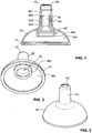
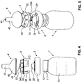
- FIGS. 1 to 5 is a preferred embodiment of the inventive teat shown.
- FIGS. 4 and 5 show a liquid container, here a baby milk bottle 1, with a neck 11 with an external thread 12.
- a liquid container here a baby milk bottle 1
- a neck 11 with an external thread 12 On the baby milk bottle 1 can be a teat 4 by means of a mounting or receiving unit 2, 3 attach.
- the receiving unit 2, 3 consists essentially of two parts: a base part 2 and a receiving head 3.
- the base part 2 is preferably made of polypropylene (PP) or a polyamide, the receiving head 3 of a combination of PP or a polyamide with silicone, rubber or TPE.
- PP polypropylene
- the receiving head 3 of a combination of PP or a polyamide with silicone, rubber or TPE.
- silicone a silicone-based plastic, rubber or TPE is used.
- the base part 2 is dimensionally stable. It consists essentially of an annular body 20 and a truncated cone 25 integrally formed thereon. Centrally in the truncated cone 25, there is a passage opening or outflow opening 24 as the inlet opening of the unit. which the container interior of the container 1 to the outside, ie the teat, connects.
- the truncated cone 25 projects beyond the annular body 20 and extends upwards towards the receiving head 3.
- the outflow opening 24 is preferably arranged in the uppermost region, preferably in the flattened tip.
- This base part 2 can be placed on the container neck 11, but without it already fixed in position relative to it, in particular against rotation.
- the stop may be, for example, an inner bearing surface in the upper region of the base ring 2.
- Other types of stops, such as protruding noses or ribs, are also possible.
- the receiving head 3 is also annular and preferably rotationally symmetrical.
- the recording head 3 consists essentially of two areas.
- the lower, preferably hard area is formed here by a plurality of plug-in elements 30, which form uniformly distributed over the circumference portions of a common shell.
- the plug-in elements 30 form on their inside a common internal thread 301. Instead of an internal thread and an external thread may be present if the drinking container 1 is provided with a corresponding internal thread.
- the plug-in elements 30 can be plugged into slots 21 of the base part 2. Locking ribs 33 on the base part and on the receiving head 3 prevent the receiving head 3 from falling out of the base part 2.
- the upper portion of the pickup head 3 may be made of the same or a softer material than the lower one. It can be arbitrarily shaped in the peripheral area. Preferably, it has peripheral support bodies or structures, in this case support wings 340, which interact with the suction body or teat 4 described below.
- the teat 4 is in the FIGS. 1 to 3 good to see. He is integrally trained.
- the base body 40 has a frustoconical, dome-shaped or hemispherical base body 40 and a mouthpiece 42 formed integrally thereon.
- the mouthpiece 42 is tapered in its outer periphery relative to the base body 40, and this is widened in relation to the mouthpiece in its outer periphery.
- the base body 40 is preferably bent inwards with its lower edge, so that a radially inwardly directed flange 41 is formed.
- This flange 41 can, as shown here, be aligned with the plane defined by the lower opening of the base body. However, it may also be directed at an angle downwardly out of the opening of the body 40.
- the flange 41 is preferably formed relatively narrow and stiffened the lower portion of the body 40 is not or only slightly.
- the mouthpiece 42 is preferably formed in a known manner as a hollow cylinder or preferably as a truncated cone. It forms a thin-walled hollow body with a suction opening 43. It is bendable and / or flexibly deformable. In the mouthpiece 42, preferably in the uppermost tip, the suction opening 43 is present. From this occurs in use sucked out of the container 1 liquid.
- a suction channel 48 also called liquid or milk channel, extends inside the suction nipple 4 and opens at one end into the suction opening 43. With its second end, it protrudes into the base body 40 and forms the inlet opening of the teat 4.
- the mouthpiece 42 is double-walled over part of its length.
- the upper region of the mouthpiece 42 which is adjacent to the suction opening is of single-walled construction and preferably has a flange 430 projecting radially inwardly into the suction opening 43.
- the lower, the base body 40 directed towards area is double-walled.
- the double walling preferably begins at a taper 420 of the inner cross section of the mouthpiece 42.
- the inner circumferential and fully closed wall forms a tube 481. It extends at a distance from the outer wall 422 of the mouthpiece 42.
- the suction channel 48 extends inside this tube 481.
- 481 may radial or axial ribs, Pimples or other structures protrude. These structures may be arranged on the inside of the outer wall 422 and / or on the outside of the inner wall 481.
- the outer wall 422 of the mouthpiece 42 is preferably truncated or conically shaped. At least this should apply to its internal scope.
- the outer circumference of the tube 481 is preferably cylindrical.
- the inner wall 481 may be formed as flexible as the outer wall 420. Preferably, however, it is stiffer. However, it is still preferably flexible and not rigid or stiff.
- the lower region of the tube 481 protrudes into the main body 40. Its cross-section is widened, with its shape preferably following the shape of the transition region between mouthpiece 42 and base body 40. He also runs here, however, spaced from the walls.
- the lower portion of the tube 481 is formed by a circumferential skirt 46. This apron 46 protrudes to the recording head 3. On the skirt 46, an inwardly or outwardly projecting flange 460 is preferably formed.
- the suction channel 48 extends in a chamber or cavity 421 which is present in the interior of the mouthpiece 42 and adjoins the taper 420. It has a larger cross section than the taper 420. Preferably, this cavity as well as the suction opening has a substantially round cross section. Since the mouthpiece 42 is formed relatively soft, the mouthpiece 42, in particular the chamber 421 and the suction port 43 is deformed in the intended use. They preferably take an oval shape. The cavity 421 can also be longer but narrower. This shape may change during the sucking process according to the baby.
- the mouthpiece is preferably flexible over its entire length. Preferably, in the intended use, no parts projecting the mouthpiece over a substantial part of its length project into it, so that it remains deformable.
- the suction port 43 is connected in the mounted state via the cavity 421, the tube 481 and then via the passage opening 32 and the flow opening 24 with the interior of the container 1, so that the baby through this opening his drink, e.g. Tea, water or milk, you can drink.
- his drink e.g. Tea, water or milk
- the suction nipple 4 with its base 40 can be put over the receiving head 3.
- the base body 40 is everted according to the invention until it has received its first folded appearance and thus its second stable position.
- the mouthpiece 42 is not everted. This everting can be done by hand by the lower edge of the body 40 is taken and bent upwards and outwards.
- the base body 40 takes on its own from its second stable position, as in FIG. 8 is shown. Like in this one FIG. 8 is clearly visible, is in this stable inverted position, the first connection or fastening means, namely the lower end of the suction channel 48 free and surmounted the inverted base body 40.
- the teat 4 can be gripped by hand on the now outwardly projecting inner surface 400 of the body 40 be, and the free end of the tube 481, here the skirt 46, can be slipped over the truncated cone 35 and thus the passage opening 32 of the receiving head 3.
- the flange 460 of the skirt 46 engages behind a bead or a rib of the truncated cone 35 and is there sealingly. Since the skirt 46 is easily visible and easily accessible, this can be done in a simple manner.
- the main body 40 is now folded back into its stable position of use, in turn, only the free edge of the body 40 is pulled down.
- the flange 41 of the base body 40 engages behind the projecting edge between the upper and lower regions of the receiving head 3 and lies flat and sealing against the outer sealing surface 310 of the receiving head 3.
- the suction nipple 4 is now mounted on the receiving head 3, as in FIG. 3 is shown.
- the suction nipple 4 can thus be attached to the receiving head 3 or partially put over him. Subsequently, the recording head 3 can be inserted into the base part 2. The recording head 3 can be stuck in the base part 2, if this is free, but also if it is already on the container neck 1. Since the base part 2 in the axial direction with respect to the receiving head 2 can still move easily, the teat 4 can optionally be slipped over the former only when plugged recording head 3 / base part 2.
- the base part 2 or the receiving head 3 By turning the base part 2 or the receiving head 3 on the container neck 11, the two threads, external thread 12 and internal thread 301 engage in one another.
- the recording head 3 runs down the thread along. With him the base part is pulled down to its lower stop.
- Base part 2 and receiving head 3 are now mounted on the container 1 and secured against rotation relative to each other.
- the outer sealing surface 270 of the base part 2 is now pressed relative to the outer sealing surface 310 of the receiving head 3. They clamp the flange 41 of the suction nipple 4 and thus ensure a fluid and airtight connection between the nipple 4, receiving head 3 and base part 2.
- a differently shaped lower edge 41 of the teat 4 between the two parts 2, 3 are clamped sealing.
- the teat can be mounted in a simple manner despite relatively complicated internal structure.
- the teat still has a third stable position and thus a second everted appearance.
- the tube 481 can be pulled out of the mouthpiece 42.
- the mouthpiece 42 can thus also be everted into a stable position.
- the teat forms a shape in which the base body 40 is slipped in the direction of the mouthpiece 42 and the suction channel 48 is pulled out of the mouthpiece 42. This is in FIG. 9 shown.
- the base body 40 encloses the mouthpiece practically from the upper end of the suction channel 48, ie from the taper 480.
- the suction nipple everted in this way can be cleaned very well. Preferably, it is also produced in this everted position.
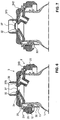
- FIGS. 6 and 7 a further receiving unit for receiving the inventive teat 4 is shown.
- the connection of the individual parts of the receiving unit is similar or the same as in the previous example.
- a self-contained valve membrane 37 is formed on the recording head 3. It covers the outflow opening 24 of the base part 2. In its peripheral region, which no longer covers the outflow opening 24, the valve membrane 37 has a small opening, the passage opening 32. This through hole 32 is located above the inner surface 241 of the base ring 2.
- the valve diaphragm 37 is preferably integrally formed on the receiving head 3. Either she herself is made of a soft material and the remaining head 3 is made of a hard material. However, for example, it may also be integrally formed together with soft support structures, here supporting cushions 340 ', and adhered to the hard part of the receiving head 3, welded to it or sprayed onto it.
- valve membrane 37 is surrounded by an upstanding and circumferential collar 39, which may also be formed of hard or soft material integral with the rest of the receiving head 3.
- This collar 39 preferably has circumferential outer ribs, which are not shown here.
- the valve membrane 37 forms a check valve, which is connected via a ring joint or hinge 370 with the remaining receiving head 3.
- the outside of this ring joint 370 arranged through hole 32 forms a flow restrictor.
- This flow restrictor 32 has a smaller cross-sectional area than the subsequent areas through which the liquid flows.
- the milk or central channel 48 and the suction opening 43 have a larger cross-sectional area.
- the suction channel 48 may have one or more constrictions spaced from the suction opening 43.
- the passage opening 32 and the check valve 37 is arranged outside the mouthpiece 42.
- the suction opening 43 and, in a preferred embodiment, the milk channel 48 has a cross-sectional area which is a multiple of the cross-sectional area of the passage opening 32.
- the cross-sectional area of the suction opening 43 is more than 10 times, in particular more than 50 times, and preferably more than 100 times larger than that of the passage opening 32.
- the entire region of the suction channel 48 extending in the mouthpiece 42 has one indicated above Factors larger cross-sectional area. Typical diameters of the suction opening 43 are 7 mm and the passage opening is 0.25 to 0.7 mm.
- both the flow restrictor and the check valve are present.
- no check valve is present, but only the flow restrictor forming passage opening 32.
- This may be centrally or centrally located in the head part 3.
- a plurality of through-openings may be present as long as they together have a cross-sectional area for the flow of the liquid, this area being smaller than the cross-sectional area of the suction opening 43.
- the through-opening serving as a flow restrictor may also be arranged in the base part 2.
- a plurality of passage openings can be distributed over the peripheral circumference of the membrane.
- the area around the at least one passage opening may also be formed of hard material and the soft part of the membrane may be formed adjacent thereto.
- a differently shaped teat unit with the inventive arrangement of large suction opening and recessed passage opening be present.
- the liquid container may be provided with the outflow opening 24, which is closed by the membrane.
- the outflow opening 24 may be selected to be so small that it itself forms the passage opening and thus the flow restrictor.
- the teat 4 may be attached in other ways.
- the skirt 46 may be inserted into the collar 39.
- the inventive nipple can be connected to the feeding bottle in a simple and hygienic manner, is easy to clean and allows the most lifelike sucking possible.
Landscapes
- Health & Medical Sciences (AREA)
- Life Sciences & Earth Sciences (AREA)
- Animal Behavior & Ethology (AREA)
- General Health & Medical Sciences (AREA)
- Public Health (AREA)
- Veterinary Medicine (AREA)
- Physics & Mathematics (AREA)
- Fluid Mechanics (AREA)
- Medical Preparation Storing Or Oral Administration Devices (AREA)
Claims (13)
- Tétine (4) pour la connexion à une unité de réception (2, 3) d'un récipient de boisson (1), présentant
un corps de base (40) et
un embout (42) se raccordant au corps de base (40), rétréci par rapport au corps de base (40), comprenant au moins une ouverture de succion (43) et une extrémité libre,
la tétine (4) présentant un premier élément de connexion (46) pour la connexion à l'unité de réception (2, 3) et un deuxième élément de connexion (41) pour la connexion à l'unité de réception (2, 3) ainsi qu'un canal de succion (48), le canal de succion (48) s'étendant dans l'embout (42), débouchant avec une première extrémité dans l'ouverture de succion (43) et étant orienté avec une deuxième extrémité (46) vers le corps de base (40) et cette deuxième extrémité (46) formant le premier élément de connexion pour la connexion hermétique à l'unité de réception (2, 3),
le corps de base (40) étant configuré de manière à pouvoir être rabattu vers l'extrémité libre de l'embout (42) et la tétine (4) étant configurée de manière à pouvoir être rabattue au niveau d'au moins un deuxième endroit, caractérisée en ce que la tétine présente un état de base stable, un premier état rabattu stable et au moins un deuxième état rabattu stable, l'au moins un deuxième état rabattu stable se distinguant du premier état stable et de l'état de base par sa forme d'aspect extérieur de telle sorte que la tétine puisse être mieux nettoyée. - Tétine selon la revendication 1, dans laquelle l'embout (42) est configuré de manière rabattable dans la région entre son extrémité libre et sa transition au corps de base (40).
- Tétine (4) selon l'une quelconque des revendications 1 ou 2, dans laquelle le canal de succion (48) s'étend au moins en partie dans un tube (481) qui s'étend au moins en partie à l'intérieur de l'embout (42) et à distance d'un côté intérieur de l'embout (42), le tube (481) présentant une première extrémité de tube qui est connectée à l'embout (42), et une deuxième extrémité de tube libre (46) formant la deuxième extrémité du canal de succion (48) et la première extrémité de tube se terminant à distance de l'extrémité libre à l'intérieur de l'embout (42).
- Tétine selon la revendication 3, dans laquelle le canal de succion (48) s'étend entre la première extrémité de tube et l'ouverture de succion (43) dans une chambre à l'intérieur de l'embout (42).
- Tétine selon l'une quelconque des revendications 3 ou 4, dans laquelle la tétine est réalisée d'une seule pièce et dans laquelle l'embout (42) est réalisé avec une double paroi avec une paroi extérieure (422) fermée sur sa périphérie et une paroi intérieure (481) disposée à distance de la paroi extérieure (422) et fermée sur sa périphérie, la paroi intérieure (481) formant ledit tube.
- Tétine selon l'une quelconque des revendications 4 ou 5, dans laquelle l'embout (42) est réalisé avec une paroi dans une région supérieure adjacente à l'ouverture de succion (43) et avec deux parois dans une région inférieure adjacente au corps de base (40).
- Tétine selon l'une quelconque des revendications 3 à 6, dans laquelle le tube (481) pénètre avec sa deuxième extrémité de tube (46) dans le corps de base (40).
- Tétine selon la revendication 7, dans laquelle le tube (481) est élargi au niveau de sa périphérie dans la région de la deuxième extrémité de tube et forme une jupe de forme cylindrique creuse ou conique (46) qui présente de préférence à son extrémité libre une bride (460).
- Tétine selon l'une quelconque des revendications 3 à 8, dans laquelle l'embout (42) est réalisé sous forme conique au moins sur la région traversée par le tube (481) et/ou dans laquelle au moins la partie du tube (48) s'étendant à l'intérieur de l'embout (42) est réalisée sous forme cylindrique creuse.
- Tétine selon l'une quelconque des revendications 1 à 9, dans laquelle l'embout (42) est configuré de manière rabattable vers l'ouverture de succion (43) dans la région de la connexion à la première extrémité de tube, de telle sorte que dans l'état rabattu, le tube (481) soit essentiellement exposé.
- Tétine selon l'une quelconque des revendications 1 à 10, dans laquelle l'embout (42) et le tube (481) sont réalisés sous forme souple flexible.
- Unité de tétine pour l'aspiration d'un liquide hors d'un récipient de liquide (1), l'unité de tétine présentant une tétine (4) selon l'une quelconque des revendications 1 à 11 et un limiteur de débit avec une ouverture de passage (32), la tétine (4) présentant un embout (42) et un corps de base (40) façonné sur l'embout (42), s'élargissant par rapport à l'embout (42), une ouverture de succion (43) étant prévue dans l'embout (42), et le limiteur de débit définissant un débit maximum du liquide s'écoulant depuis le récipient de liquide à travers l'ouverture de succion (43),
caractérisée en ce que
le limiteur de débit est disposé à l'extérieur de l'embout (42) et en ce que l'ouverture de succion (43) présente une surface en section transversale plus grande que l'ouverture de passage (32) du limiteur de débit. - Unité de tétine pour l'aspiration d'un liquide hors d'un récipient de liquide, dans laquelle l'unité de tétine présente une tétine (4) selon l'une quelconque des revendications 1 à 11 et un limiteur de débit avec une ouverture de passage (32), la tétine (4) présentant un embout (42) et un corps de base (40) façonné sur l'embout (42), s'élargissant par rapport à l'embout (42), une ouverture de succion (43) étant prévue dans l'embout (42), et le limiteur de débit définissant un débit maximum du liquide s'écoulant depuis le récipient de liquide à travers l'ouverture de succion (43),
caractérisée en ce que
le limiteur de débit est disposé à l'extérieur de l'embout (42) et en ce que l'unité de tétine présente un clapet unidirectionnel (37) qui est disposé à l'extérieur de l'embout (42) et le limiteur de débit étant disposé dans le clapet unidirectionnel ou dans une région adjacente à celui-ci.
Priority Applications (1)
| Application Number | Priority Date | Filing Date | Title |
|---|---|---|---|
| PL09761232T PL2291164T3 (pl) | 2008-06-12 | 2009-06-09 | Smoczek |
Applications Claiming Priority (3)
| Application Number | Priority Date | Filing Date | Title |
|---|---|---|---|
| CH8972008 | 2008-06-12 | ||
| CH1762009 | 2009-02-06 | ||
| PCT/CH2009/000193 WO2009149574A1 (fr) | 2008-06-12 | 2009-06-09 | Tétine |
Publications (2)
| Publication Number | Publication Date |
|---|---|
| EP2291164A1 EP2291164A1 (fr) | 2011-03-09 |
| EP2291164B1 true EP2291164B1 (fr) | 2016-05-18 |
Family
ID=40888123
Family Applications (1)
| Application Number | Title | Priority Date | Filing Date |
|---|---|---|---|
| EP09761232.9A Not-in-force EP2291164B1 (fr) | 2008-06-12 | 2009-06-09 | Tétine |
Country Status (4)
| Country | Link |
|---|---|
| US (1) | US8251234B2 (fr) |
| EP (1) | EP2291164B1 (fr) |
| PL (1) | PL2291164T3 (fr) |
| WO (1) | WO2009149574A1 (fr) |
Families Citing this family (7)
| Publication number | Priority date | Publication date | Assignee | Title |
|---|---|---|---|---|
| JP5486214B2 (ja) * | 2009-05-20 | 2014-05-07 | 株式会社マキタ | 動力工具 |
| US8371464B2 (en) * | 2010-10-27 | 2013-02-12 | Medela Holding Ag | Container with adjustable date indicium |
| AU2012240417A1 (en) * | 2011-04-07 | 2013-10-31 | David A. Tesini | Teat for feeding bottle |
| US9060918B1 (en) * | 2011-05-31 | 2015-06-23 | Buon Bambini LLC | Attachable mouthpiece spout for use with food packaging |
| US8689988B2 (en) * | 2012-05-07 | 2014-04-08 | Tao Xu | Bottle cap having removal tracking indicia |
| EP3742942A4 (fr) * | 2018-01-19 | 2022-04-06 | The Board of Regents of the University of Texas System | Appareil soulageant le hoquet |
| USD1010104S1 (en) | 2020-02-26 | 2024-01-02 | Higher Innovations, Inc. | Hiccup relieving apparatus |
Family Cites Families (23)
| Publication number | Priority date | Publication date | Assignee | Title |
|---|---|---|---|---|
| US582159A (en) | 1897-05-04 | Nipple | ||
| US689987A (en) * | 1901-06-17 | 1901-12-31 | David Pick | Nursing-nipple. |
| US981072A (en) * | 1909-09-28 | 1911-01-10 | William More Decker | Nursing-nipple. |
| US1543427A (en) * | 1924-08-06 | 1925-06-23 | Carroll K Denney | Nipple |
| US1569693A (en) * | 1924-11-07 | 1926-01-12 | Llewellyn C Young | Nursing nipple |
| US1656157A (en) * | 1926-03-27 | 1928-01-17 | Josephine L Correnti | Nipple for nursing bottles |
| US1735670A (en) * | 1928-06-15 | 1929-11-12 | Blumenfeld Marcus | Safety nipple |
| GB347368A (en) * | 1930-02-24 | 1931-04-30 | Leslie Reader | Improvements in or relating to teats for feeding bottles and the like |
| US1902433A (en) * | 1931-07-02 | 1933-03-21 | Gen Health Corp | Nipple |
| US1904710A (en) * | 1931-08-19 | 1933-04-18 | Barkan Irving | Nipple |
| US2133411A (en) * | 1934-02-27 | 1938-10-18 | Zohe Ludwig Alvine | Baby nurser |
| US3207349A (en) * | 1963-12-18 | 1965-09-21 | George B Rabe | Nursing bottle |
| US3704803A (en) * | 1971-07-13 | 1972-12-05 | Charles L Ponder | Nursing bottle |
| US4623069A (en) * | 1984-04-12 | 1986-11-18 | Baxter Travenol Laboratories, Inc. | Nipple and nursing container |
| JPH01244761A (ja) | 1988-03-26 | 1989-09-29 | Jiekusu Kk | 哺乳瓶用乳首 |
| JPH02161950A (ja) * | 1988-12-15 | 1990-06-21 | Jiekusu Kk | 乳首 |
| US5244105A (en) * | 1990-01-12 | 1993-09-14 | Johnson & Johnson Consumer Products, Inc. | Adjustable air inflow for feeding-bottle device |
| US5897007A (en) * | 1996-05-13 | 1999-04-27 | Schein; Douglas | Nursing bottle |
| US5704505A (en) | 1996-08-05 | 1998-01-06 | Singh; Hemchandre | Infant bottle feeding system |
| US6126679A (en) * | 1999-04-12 | 2000-10-03 | Botts; Lynne Marie | Nipple for use with liquid and medicine dispensing bottle |
| US6708833B2 (en) | 2001-10-12 | 2004-03-23 | Kenneth W. Kolb | Infant nipple attachment |
| GB0215006D0 (en) | 2002-06-28 | 2002-08-07 | Jackel Int Ltd | A drinking vessel |
| US20070045215A1 (en) * | 2005-08-26 | 2007-03-01 | Insta-Mix, Inc. Subsidiary A (Dba Umix, Inc.) | Beverage container vent mechanism including perforated elastic membrane and support plate |
-
2009
- 2009-06-09 EP EP09761232.9A patent/EP2291164B1/fr not_active Not-in-force
- 2009-06-09 WO PCT/CH2009/000193 patent/WO2009149574A1/fr active Application Filing
- 2009-06-09 PL PL09761232T patent/PL2291164T3/pl unknown
- 2009-06-11 US US12/483,054 patent/US8251234B2/en not_active Expired - Fee Related
Also Published As
| Publication number | Publication date |
|---|---|
| WO2009149574A1 (fr) | 2009-12-17 |
| US8251234B2 (en) | 2012-08-28 |
| PL2291164T3 (pl) | 2017-06-30 |
| US20090314736A1 (en) | 2009-12-24 |
| EP2291164A1 (fr) | 2011-03-09 |
Similar Documents
| Publication | Publication Date | Title |
|---|---|---|
| EP2293758B1 (fr) | Ensemble tétine | |
| EP2291164B1 (fr) | Tétine | |
| EP2467118B1 (fr) | Unité tétine | |
| AT405717B (de) | Schnuller-sauger | |
| EP2691066B1 (fr) | Unité à tétine | |
| EP3236812B1 (fr) | Récipient pour boisson pourvu d'une valve d'aspiration | |
| EP3258981B1 (fr) | Adaptateur doté d'une membrane de séparation de fluides pour une téterelle | |
| EP1675546A2 (fr) | Bouteille, en particulier biberon, et procede de production associe | |
| EP3541250B1 (fr) | Accessoire pour boire pour un récipient à boire et récipient à boire pourvu d'un tel accessoire | |
| EP3258982A1 (fr) | Téterelle à bord flexible | |
| EP2358329B1 (fr) | Unité à tétine pour biberon | |
| EP2291165B1 (fr) | Tétine | |
| EP1585412A1 (fr) | Ensemble soupape | |
| AT413978B (de) | Luftventil für einen deckel eines trinkbehälters | |
| DE602004005555T2 (de) | Sauger für Säuglingsflasche | |
| DE202004014860U1 (de) | Aufbau eines Schnullers für eine Milchflasche |
Legal Events
| Date | Code | Title | Description |
|---|---|---|---|
| PUAI | Public reference made under article 153(3) epc to a published international application that has entered the european phase |
Free format text: ORIGINAL CODE: 0009012 |
|
| 17P | Request for examination filed |
Effective date: 20110106 |
|
| AK | Designated contracting states |
Kind code of ref document: A1 Designated state(s): AT BE BG CH CY CZ DE DK EE ES FI FR GB GR HR HU IE IS IT LI LT LU LV MC MK MT NL NO PL PT RO SE SI SK TR |
|
| AX | Request for extension of the european patent |
Extension state: AL BA RS |
|
| DAX | Request for extension of the european patent (deleted) | ||
| 17Q | First examination report despatched |
Effective date: 20140122 |
|
| GRAP | Despatch of communication of intention to grant a patent |
Free format text: ORIGINAL CODE: EPIDOSNIGR1 |
|
| INTG | Intention to grant announced |
Effective date: 20151215 |
|
| GRAS | Grant fee paid |
Free format text: ORIGINAL CODE: EPIDOSNIGR3 |
|
| GRAA | (expected) grant |
Free format text: ORIGINAL CODE: 0009210 |
|
| AK | Designated contracting states |
Kind code of ref document: B1 Designated state(s): AT BE BG CH CY CZ DE DK EE ES FI FR GB GR HR HU IE IS IT LI LT LU LV MC MK MT NL NO PL PT RO SE SI SK TR |
|
| REG | Reference to a national code |
Ref country code: GB Ref legal event code: FG4D Free format text: NOT ENGLISH |
|
| REG | Reference to a national code |
Ref country code: CH Ref legal event code: EP |
|
| REG | Reference to a national code |
Ref country code: IE Ref legal event code: FG4D Free format text: LANGUAGE OF EP DOCUMENT: GERMAN Ref country code: AT Ref legal event code: REF Ref document number: 799776 Country of ref document: AT Kind code of ref document: T Effective date: 20160615 |
|
| REG | Reference to a national code |
Ref country code: DE Ref legal event code: R096 Ref document number: 502009012599 Country of ref document: DE |
|
| REG | Reference to a national code |
Ref country code: FR Ref legal event code: PLFP Year of fee payment: 8 |
|
| REG | Reference to a national code |
Ref country code: NL Ref legal event code: FP |
|
| REG | Reference to a national code |
Ref country code: LT Ref legal event code: MG4D |
|
| PG25 | Lapsed in a contracting state [announced via postgrant information from national office to epo] |
Ref country code: LT Free format text: LAPSE BECAUSE OF FAILURE TO SUBMIT A TRANSLATION OF THE DESCRIPTION OR TO PAY THE FEE WITHIN THE PRESCRIBED TIME-LIMIT Effective date: 20160518 Ref country code: NO Free format text: LAPSE BECAUSE OF FAILURE TO SUBMIT A TRANSLATION OF THE DESCRIPTION OR TO PAY THE FEE WITHIN THE PRESCRIBED TIME-LIMIT Effective date: 20160818 Ref country code: FI Free format text: LAPSE BECAUSE OF FAILURE TO SUBMIT A TRANSLATION OF THE DESCRIPTION OR TO PAY THE FEE WITHIN THE PRESCRIBED TIME-LIMIT Effective date: 20160518 |
|
| PG25 | Lapsed in a contracting state [announced via postgrant information from national office to epo] |
Ref country code: SE Free format text: LAPSE BECAUSE OF FAILURE TO SUBMIT A TRANSLATION OF THE DESCRIPTION OR TO PAY THE FEE WITHIN THE PRESCRIBED TIME-LIMIT Effective date: 20160518 Ref country code: PT Free format text: LAPSE BECAUSE OF FAILURE TO SUBMIT A TRANSLATION OF THE DESCRIPTION OR TO PAY THE FEE WITHIN THE PRESCRIBED TIME-LIMIT Effective date: 20160919 Ref country code: GR Free format text: LAPSE BECAUSE OF FAILURE TO SUBMIT A TRANSLATION OF THE DESCRIPTION OR TO PAY THE FEE WITHIN THE PRESCRIBED TIME-LIMIT Effective date: 20160819 Ref country code: ES Free format text: LAPSE BECAUSE OF FAILURE TO SUBMIT A TRANSLATION OF THE DESCRIPTION OR TO PAY THE FEE WITHIN THE PRESCRIBED TIME-LIMIT Effective date: 20160518 Ref country code: LV Free format text: LAPSE BECAUSE OF FAILURE TO SUBMIT A TRANSLATION OF THE DESCRIPTION OR TO PAY THE FEE WITHIN THE PRESCRIBED TIME-LIMIT Effective date: 20160518 Ref country code: HR Free format text: LAPSE BECAUSE OF FAILURE TO SUBMIT A TRANSLATION OF THE DESCRIPTION OR TO PAY THE FEE WITHIN THE PRESCRIBED TIME-LIMIT Effective date: 20160518 |
|
| PGFP | Annual fee paid to national office [announced via postgrant information from national office to epo] |
Ref country code: FR Payment date: 20160713 Year of fee payment: 8 |
|
| PG25 | Lapsed in a contracting state [announced via postgrant information from national office to epo] |
Ref country code: IT Free format text: LAPSE BECAUSE OF FAILURE TO SUBMIT A TRANSLATION OF THE DESCRIPTION OR TO PAY THE FEE WITHIN THE PRESCRIBED TIME-LIMIT Effective date: 20160518 |
|
| PGFP | Annual fee paid to national office [announced via postgrant information from national office to epo] |
Ref country code: TR Payment date: 20160802 Year of fee payment: 8 |
|
| PG25 | Lapsed in a contracting state [announced via postgrant information from national office to epo] |
Ref country code: DK Free format text: LAPSE BECAUSE OF FAILURE TO SUBMIT A TRANSLATION OF THE DESCRIPTION OR TO PAY THE FEE WITHIN THE PRESCRIBED TIME-LIMIT Effective date: 20160518 Ref country code: CZ Free format text: LAPSE BECAUSE OF FAILURE TO SUBMIT A TRANSLATION OF THE DESCRIPTION OR TO PAY THE FEE WITHIN THE PRESCRIBED TIME-LIMIT Effective date: 20160518 Ref country code: EE Free format text: LAPSE BECAUSE OF FAILURE TO SUBMIT A TRANSLATION OF THE DESCRIPTION OR TO PAY THE FEE WITHIN THE PRESCRIBED TIME-LIMIT Effective date: 20160518 Ref country code: RO Free format text: LAPSE BECAUSE OF FAILURE TO SUBMIT A TRANSLATION OF THE DESCRIPTION OR TO PAY THE FEE WITHIN THE PRESCRIBED TIME-LIMIT Effective date: 20160518 Ref country code: SK Free format text: LAPSE BECAUSE OF FAILURE TO SUBMIT A TRANSLATION OF THE DESCRIPTION OR TO PAY THE FEE WITHIN THE PRESCRIBED TIME-LIMIT Effective date: 20160518 |
|
| REG | Reference to a national code |
Ref country code: CH Ref legal event code: PL |
|
| REG | Reference to a national code |
Ref country code: DE Ref legal event code: R097 Ref document number: 502009012599 Country of ref document: DE |
|
| REG | Reference to a national code |
Ref country code: IE Ref legal event code: MM4A |
|
| PLBE | No opposition filed within time limit |
Free format text: ORIGINAL CODE: 0009261 |
|
| STAA | Information on the status of an ep patent application or granted ep patent |
Free format text: STATUS: NO OPPOSITION FILED WITHIN TIME LIMIT |
|
| PG25 | Lapsed in a contracting state [announced via postgrant information from national office to epo] |
Ref country code: MC Free format text: LAPSE BECAUSE OF FAILURE TO SUBMIT A TRANSLATION OF THE DESCRIPTION OR TO PAY THE FEE WITHIN THE PRESCRIBED TIME-LIMIT Effective date: 20160518 |
|
| 26N | No opposition filed |
Effective date: 20170221 |
|
| PG25 | Lapsed in a contracting state [announced via postgrant information from national office to epo] |
Ref country code: CH Free format text: LAPSE BECAUSE OF NON-PAYMENT OF DUE FEES Effective date: 20160630 Ref country code: LI Free format text: LAPSE BECAUSE OF NON-PAYMENT OF DUE FEES Effective date: 20160630 |
|
| PG25 | Lapsed in a contracting state [announced via postgrant information from national office to epo] |
Ref country code: SI Free format text: LAPSE BECAUSE OF FAILURE TO SUBMIT A TRANSLATION OF THE DESCRIPTION OR TO PAY THE FEE WITHIN THE PRESCRIBED TIME-LIMIT Effective date: 20160518 Ref country code: IE Free format text: LAPSE BECAUSE OF NON-PAYMENT OF DUE FEES Effective date: 20160609 |
|
| PGFP | Annual fee paid to national office [announced via postgrant information from national office to epo] |
Ref country code: GB Payment date: 20170620 Year of fee payment: 9 Ref country code: DE Payment date: 20170621 Year of fee payment: 9 |
|
| REG | Reference to a national code |
Ref country code: AT Ref legal event code: MM01 Ref document number: 799776 Country of ref document: AT Kind code of ref document: T Effective date: 20160609 |
|
| PGFP | Annual fee paid to national office [announced via postgrant information from national office to epo] |
Ref country code: PL Payment date: 20170525 Year of fee payment: 9 Ref country code: NL Payment date: 20170620 Year of fee payment: 9 Ref country code: BE Payment date: 20170620 Year of fee payment: 9 |
|
| PG25 | Lapsed in a contracting state [announced via postgrant information from national office to epo] |
Ref country code: AT Free format text: LAPSE BECAUSE OF NON-PAYMENT OF DUE FEES Effective date: 20160609 |
|
| REG | Reference to a national code |
Ref country code: FR Ref legal event code: ST Effective date: 20180228 |
|
| PG25 | Lapsed in a contracting state [announced via postgrant information from national office to epo] |
Ref country code: FR Free format text: LAPSE BECAUSE OF NON-PAYMENT OF DUE FEES Effective date: 20170630 Ref country code: CY Free format text: LAPSE BECAUSE OF FAILURE TO SUBMIT A TRANSLATION OF THE DESCRIPTION OR TO PAY THE FEE WITHIN THE PRESCRIBED TIME-LIMIT Effective date: 20160518 Ref country code: HU Free format text: LAPSE BECAUSE OF FAILURE TO SUBMIT A TRANSLATION OF THE DESCRIPTION OR TO PAY THE FEE WITHIN THE PRESCRIBED TIME-LIMIT; INVALID AB INITIO Effective date: 20090609 |
|
| PG25 | Lapsed in a contracting state [announced via postgrant information from national office to epo] |
Ref country code: MT Free format text: LAPSE BECAUSE OF FAILURE TO SUBMIT A TRANSLATION OF THE DESCRIPTION OR TO PAY THE FEE WITHIN THE PRESCRIBED TIME-LIMIT Effective date: 20160518 Ref country code: LU Free format text: LAPSE BECAUSE OF NON-PAYMENT OF DUE FEES Effective date: 20160609 Ref country code: MK Free format text: LAPSE BECAUSE OF FAILURE TO SUBMIT A TRANSLATION OF THE DESCRIPTION OR TO PAY THE FEE WITHIN THE PRESCRIBED TIME-LIMIT Effective date: 20160518 Ref country code: IS Free format text: LAPSE BECAUSE OF FAILURE TO SUBMIT A TRANSLATION OF THE DESCRIPTION OR TO PAY THE FEE WITHIN THE PRESCRIBED TIME-LIMIT Effective date: 20160518 |
|
| PG25 | Lapsed in a contracting state [announced via postgrant information from national office to epo] |
Ref country code: BG Free format text: LAPSE BECAUSE OF FAILURE TO SUBMIT A TRANSLATION OF THE DESCRIPTION OR TO PAY THE FEE WITHIN THE PRESCRIBED TIME-LIMIT Effective date: 20160518 |
|
| REG | Reference to a national code |
Ref country code: DE Ref legal event code: R119 Ref document number: 502009012599 Country of ref document: DE |
|
| REG | Reference to a national code |
Ref country code: NL Ref legal event code: MM Effective date: 20180701 |
|
| GBPC | Gb: european patent ceased through non-payment of renewal fee |
Effective date: 20180609 |
|
| REG | Reference to a national code |
Ref country code: BE Ref legal event code: MM Effective date: 20180630 |
|
| PG25 | Lapsed in a contracting state [announced via postgrant information from national office to epo] |
Ref country code: NL Free format text: LAPSE BECAUSE OF NON-PAYMENT OF DUE FEES Effective date: 20180701 |
|
| PG25 | Lapsed in a contracting state [announced via postgrant information from national office to epo] |
Ref country code: GB Free format text: LAPSE BECAUSE OF NON-PAYMENT OF DUE FEES Effective date: 20180609 Ref country code: DE Free format text: LAPSE BECAUSE OF NON-PAYMENT OF DUE FEES Effective date: 20190101 |
|
| PG25 | Lapsed in a contracting state [announced via postgrant information from national office to epo] |
Ref country code: BE Free format text: LAPSE BECAUSE OF NON-PAYMENT OF DUE FEES Effective date: 20180630 |
|
| PG25 | Lapsed in a contracting state [announced via postgrant information from national office to epo] |
Ref country code: PL Free format text: LAPSE BECAUSE OF NON-PAYMENT OF DUE FEES Effective date: 20180609 |
|
| PG25 | Lapsed in a contracting state [announced via postgrant information from national office to epo] |
Ref country code: TR Free format text: LAPSE BECAUSE OF NON-PAYMENT OF DUE FEES Effective date: 20170609 |