EP2290840B1 - Drahtloses Kommunikationsverfahren und Relaisvorrichtung - Google Patents
Drahtloses Kommunikationsverfahren und Relaisvorrichtung Download PDFInfo
- Publication number
- EP2290840B1 EP2290840B1 EP10174428.2A EP10174428A EP2290840B1 EP 2290840 B1 EP2290840 B1 EP 2290840B1 EP 10174428 A EP10174428 A EP 10174428A EP 2290840 B1 EP2290840 B1 EP 2290840B1
- Authority
- EP
- European Patent Office
- Prior art keywords
- signal
- wireless communication
- section
- wireless
- communication apparatus
- Prior art date
- Legal status (The legal status is an assumption and is not a legal conclusion. Google has not performed a legal analysis and makes no representation as to the accuracy of the status listed.)
- Not-in-force
Links
Images


Classifications
-
- H—ELECTRICITY
- H04—ELECTRIC COMMUNICATION TECHNIQUE
- H04B—TRANSMISSION
- H04B7/00—Radio transmission systems, i.e. using radiation field
- H04B7/14—Relay systems
- H04B7/15—Active relay systems
- H04B7/155—Ground-based stations
- H04B7/15528—Control of operation parameters of a relay station to exploit the physical medium
-
- H—ELECTRICITY
- H04—ELECTRIC COMMUNICATION TECHNIQUE
- H04B—TRANSMISSION
- H04B7/00—Radio transmission systems, i.e. using radiation field
- H04B7/14—Relay systems
- H04B7/15—Active relay systems
- H04B7/155—Ground-based stations
- H04B7/15592—Adapting at the relay station communication parameters for supporting cooperative relaying, i.e. transmission of the same data via direct - and relayed path
-
- H—ELECTRICITY
- H04—ELECTRIC COMMUNICATION TECHNIQUE
- H04B—TRANSMISSION
- H04B7/00—Radio transmission systems, i.e. using radiation field
- H04B7/24—Radio transmission systems, i.e. using radiation field for communication between two or more posts
- H04B7/26—Radio transmission systems, i.e. using radiation field for communication between two or more posts at least one of which is mobile
- H04B7/2603—Arrangements for wireless physical layer control
- H04B7/2606—Arrangements for base station coverage control, e.g. by using relays in tunnels
Definitions
- Embodiments discussed herein are related to a wireless communication method and a relay apparatus for relaying a wireless signal.
- a method of relaying a wireless signal using a relay apparatus has been put to practical use.
- An example of such a relay apparatus is, for example, a booster device that does not perform regenerative relay.
- the wireless relay apparatus includes a downlink relaying section, a downlink power control command obtaining section, a downlink reception status determining section, and a relay controlling section.
- the downlink relaying section amplifies a downlink signal transmitted from the base station and transmits the amplified downlink signal to a mobile station.
- the downlink power control command obtaining section obtains, from an uplink signal transmitted from the mobile station, a downlink power control command for controlling transmission power of the base station.
- the downlink reception status determining section determines, in accordance with the downlink power control command, whether the mobile station is in a reception status requiring amplification of the downlink signal.
- the relay controlling section stops the amplification process performed by the downlink relaying section when it has been determined that the mobile station is not in a reception status requiring amplification of the downlink signal.
- Japanese Laid-open Patent Publication No. 2009-55185 discloses a related technique.
- 3rd Generation Partnership Project; Technical Specification Group Radio Access Network; Further Advancements for E-UTRA Physical Layer Aspects (Release 9) discloses general information regarding physical layer evolution of E-UTRA systems, including details of relay functionality.
- a wireless communication method executed by a wireless communication system including a relay apparatus, a first wireless communication apparatus, and a second wireless communication apparatus.
- the wireless communication method includes the following operations. Upon receiving a wireless signal from the first wireless communication apparatus, the relay apparatus adds advice information, which indicates that the wireless signal has been relayed, to the received wireless signal.
- the relay apparatus transmits the wireless signal to which the advice information has been added to the second wireless communication apparatus.
- the second wireless communication apparatus detects the advice information to determine whether the wireless signal has been relayed.
- the relay apparatus adds the advice information by inverting a sign of a frequency of the wireless signal.
- a wireless communication apparatus may preferably perform processing in accordance with whether a wireless signal has been relayed.
- the settings of a communication parameter used for transmitting a wireless signal may preferably be changed in accordance with whether the wireless signal has been relayed.
- Examples of such a communication parameter include a parameter for determining a communication method, i.e., whether to use Multiple Input Multiple Output (MIMO) transmission, or a parameter for transmission power.
- MIMO Multiple Input Multiple Output
- a relay apparatus may receive a signal whose transmission power after being relayed exceeds an allowable transmission power of the relay apparatus.
- a positioning system that receives positioning signals from multiple positioning signal transmitting apparatuses to perform positioning in accordance with a delay time of each positioning signal.
- the positioning accuracy may be degraded.
- the wireless communication apparatus may change its processing in accordance with whether the wireless signal has been relayed.
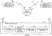
- FIG. 1 illustrates an example of a configuration of a communication system 1 according to the present embodiment.
- the communication system 1 includes wireless communication apparatuses 2 and 3, and a relay apparatus 10.
- the relay apparatus 10 relays a wireless signal transmitted from the wireless communication apparatus 3 to the wireless communication apparatus 2. That is, the relay apparatus 10 amplifies the wireless signal received from the wireless communication apparatus 3 and transmits the amplified wireless signal.
- the wireless communication apparatus 2 receives the wireless signal transmitted from the relay apparatus 10.
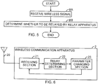
- FIG. 2 illustrates an example of a configuration of the relay apparatus 10 illustrated in FIG. 1 .
- the relay apparatus 10 includes antennas 11 and 16, a receiving section 12, an advice information adding section 13, an amplifying section 14, and a transmitting section 15.
- the receiving section 12 receives an incoming wireless signal via the antenna 11.
- the amplifying section 14 amplifies the received wireless signal, which has been received by the receiving section 12.
- the transmitting section 15 transmits the received wireless signal, which has been amplified by the amplifying section 14, via the antenna 16.
- the advice information adding section 13 adds, to the signal transmitted by the transmitting section 15, information indicating that this signal has been relayed by a relay apparatus.
- information indicating that this signal has been relayed by a relay apparatus is referred to as "advice information”.
- the advice information adding section 13 may add advice information to the signal before amplified by the amplifying section 14, or may add advice information to the signal after amplified by the amplifying section 14.
- FIG. 3 illustrates an example of an operation flow of a process performed by the relay apparatus 10 illustrated in FIG. 2 .
- the receiving section 12 receives an incoming wireless signal via the antenna 11.
- the advice information adding section 13 adds advice information to the received wireless signal.
- the amplifying section 14 amplifies the received wireless signal which has been added the advice information thereto.
- operation AB may be performed after operation AC. That is, the advice information adding section 13 may add advice information to the received wireless signal after amplified by the amplifying section 14.
- the transmitting section 15 transmits the signal, which has been added the additional information thereto and amplified by the amplifying section 14, via the antenna 16.
- advice information that is, information indicating that the wireless signal has been relayed by a relay apparatus
- the wireless communication apparatus 2 which has received the wireless signal may determine whether the received wireless signal has been relayed by a relay apparatus.
- FIG. 4 illustrates a first example of a configuration of the wireless communication apparatus 2 illustrated in FIG. 1 .
- the wireless communication apparatus 2 illustrated in FIG. 4 includes an antenna 20, a receiving section 21, and a relay determining section 22.
- the receiving section 21 receives an incoming wireless signal via the antenna 20.
- the relay determining section 22 detects advice information from the received wireless signal to determine whether the received wireless signal received by the receiving section 21 has been relayed by a relay apparatus.
- the relay determining section 22 outputs a determination result signal indicating the result of the determination.
- FIG. 5 illustrates an example of an operation flow of a process performed by the wireless communication apparatus 2 illustrated in FIG. 4 .
- the receiving section 21 receives an incoming wireless signal via the antenna 20.
- the relay determining section 22 detects advice information from the received wireless signal to determine whether the received wireless signal received in operation BA has been relayed by a relay apparatus.
- the wireless communication apparatus 2 determines whether the received wireless signal has been relayed. Thus, the wireless communication apparatus 2 may use the result of the determination in a certain process performed by the wireless communication apparatus 2.
- FIG. 6 illustrates a second example of a configuration of the wireless communication apparatus 2 illustrated in FIG. 1 .
- the difference from the first example illustrated in FIG. 4 is that the wireless communication apparatus 2 illustrated in FIG. 6 further includes a parameter changing section 23.
- the wireless communication apparatus 2 includes an antenna 20, a receiving section 21, a relay determining section 22, and the parameter changing section 23.
- the parameter changing section 23 changes a communication parameter for wireless communication between the wireless communication apparatus 3, which is the transmission source of the received wireless signal, and the wireless communication apparatus 2 in accordance with whether the received wireless signal has been relayed.
- the receiving section 21 and the relay determining section 22 are similar to those illustrated in FIG. 4 .
- the communication parameter may be, for example, a parameter for determining whether to use MIMO transmission between the wireless communication apparatuses 2 and 3.
- the communication parameter may be a parameter for transmission power to transmit the wireless signal.
- a parameter for determining whether to use MIMO transmission and a parameter indicating the strength of transmission power are exemplified.
- the following discussion does not intend to restrict the type of communication parameter to be changed in accordance with whether the received wireless signal has been relayed to these exemplary parameters.
- any type of communication parameter may be used as long as the communication parameter is meaningful to be changed in accordance with whether the received wireless signal has been relayed.
- the parameter changing section 23 uses, as the communication parameter for wireless communication between the wireless communication apparatus 3, which is the transmission source of the received wireless signal, and the wireless communication apparatus 2, a parameter used when the wireless communication apparatuses 2 and 3 directly communicate with each other.
- the parameter changing section 23 may determine whether to use MIMO transmission in accordance with the channel quality between the wireless communication apparatuses 2 and 3.
- the parameter changing section 23 may determine transmission power in accordance with the channel quality between the wireless communication apparatuses 2 and 3.
- the parameter changing section 23 uses, as the communication parameter for wireless communication between the wireless communication apparatuses 2 and 3, a parameter used when communication between the wireless communication apparatuses 2 and 3 is relayed.
- the parameter changing section 23 may determine not to perform MIMO transmission between the wireless communication apparatuses 2 and 3.
- the parameter changing section 23 may determine the strength of transmission power to be a certain upper limit when defining the strength of transmission power in transmitting the signal from the wireless communication apparatus 3 and/or the wireless communication apparatus 2 in accordance with the channel quality between the wireless communication apparatuses 2 and 3.
- the communication parameter to be changed by the parameter changing section 23 may be a communication parameter for wireless communication in which the wireless signal is transmitted from the wireless communication apparatus 2 to the wireless communication apparatus 3.
- the communication parameter to be changed by the parameter changing section 23 may be a communication parameter for wireless communication in which the wireless signal is transmitted from the wireless communication apparatus 3 to the wireless communication apparatus 2.
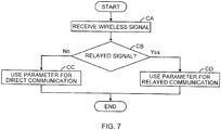
- FIG. 7 illustrates an example of an operation flow of a process performed by the wireless communication apparatus 2 illustrated in FIG. 6 .
- the receiving section 21 receives an incoming wireless signal via the antenna 20.
- the relay determining section 22 determines whether the received wireless signal received in operation CA is a relayed signal. When the received wireless signal is not a relayed signal ("No" in operation CB), the wireless communication apparatus 2 advances the process to operation CC. When the received wireless signal is a relayed signal ("Yes" in operation CB), the wireless communication apparatus 2 advances the process to operation CD.
- the parameter changing section 23 uses, as the communication parameter for wireless communication between the wireless communication apparatus 3 and the wireless communication apparatus 2, a parameter used when the wireless communication apparatuses 2 and 3 directly communicate with each other. Thereafter, the wireless communication apparatus 2 terminates the process.
- the parameter changing section 23 uses, as the communication parameter for wireless communication between the wireless communication apparatus 3 and the wireless communication apparatus 2, a parameter used when communication between the wireless communication apparatuses 2 and 3 is relayed. Thereafter, the wireless communication apparatus 2 terminates the process.
- the communication parameter used in wireless communication between the wireless communication apparatus 2 and the wireless communication apparatus 3, which is the transmission source of the received wireless signal received by the wireless communication apparatus 2 may be changed in accordance with whether the received wireless signal has been relayed. Accordingly, for example, when wireless communication between the wireless communication apparatuses 2 and 3 is relayed, communication based on MIMO transmission may be prohibited. Also, when wireless communication between the wireless communication apparatuses 2 and 3 is relayed, the strength of transmission power in transmitting the signal from each of the wireless communication apparatuses 2 and 3 may be restricted so that transmission power of the relay apparatus does not exceed the allowable transmission power.
- FIG. 8 illustrates an example of a configuration of a base station apparatus serving as the wireless communication apparatus 2 illustrated in FIG. 6 .
- the base station apparatus 100 includes a controlling section 101, a baseband signal (BB signal) processing section 102, an antenna 103, and a wireless communication section 104.
- the base station apparatus 100 further includes a channel quality indicator (CQI) measuring section 105, a CQI signal extracting section 106, a scheduler 107, and the relay determining section 22.
- the wireless communication section 104 includes a demodulating section 108.
- the scheduler 107 is given as an example of the parameter changing section 23.
- the controlling section 101 controls operations of the base station apparatus 100.
- the controlling section 101 gives, to the scheduler 107, various setting values used in scheduling for communication between the base station apparatus 100 and a mobile station apparatus.
- the controlling section 101 controls operations of the base station apparatus 100 in accordance with the schedule made by the scheduler 107.
- the baseband signal processing section 102 performs signal processing of a baseband signal for user data and control information transmitted between the base station apparatus 100 and the mobile station apparatus.
- the wireless communication section 104 transmits and receives user data and control information to/from the mobile station apparatus via the antenna 103.
- the demodulating section 108 demodulates the received wireless signal received from the mobile station apparatus.
- the CQI measuring section 105 measures the channel quality of an uplink channel from the mobile station apparatus to the base station apparatus 100 in accordance with the signal received by the wireless communication section 104.
- the CQI signal extracting section 106 extracts, from the signal transmitted from the mobile station apparatus, a CQI signal indicating the channel quality of a downlink channel measured by the mobile station apparatus.
- the scheduler 107 may generate a transmission power control signal for controlling transmission power of the uplink channel in accordance with the channel quality of the uplink channel, which has been measured by the CQI measuring section 105.
- the wireless communication section 104 transmits the transmission power control signal to the mobile station apparatus to control transmission power of the uplink channel.
- the scheduler 107 determines transmission power of the downlink channel in accordance with the CQI signal transmitted from the mobile station apparatus. The scheduler 107 determines whether to perform MIMO transmission with the mobile station apparatus, in accordance with the channel quality of the downlink channel and/or the uplink channel.
- the relay determining section 22 determines whether the received wireless signal received from the mobile station apparatus has been relayed.
- the relay determining section 22 outputs a determination result signal indicating the result of the determination to the scheduler 107.
- the scheduler 107 may control transmission power of the mobile station apparatus by using the transmission power control signal so that transmission power of the mobile station apparatus in the uplink channel does not exceed a certain upper limit.
- the scheduler 107 may restrict transmission power of the base station apparatus 100 to be a certain upper limit or less, assuming that wireless communication in the downlink is similarly relayed.
- the scheduler 107 may determine not to perform MIMO transmission with the mobile station apparatus.
- the communication parameter used in uplink and/or downlink communication between the base station apparatus 100 and the mobile station apparatus may be changed in accordance with whether the received wireless signal received by the base station apparatus 100 has been relayed.
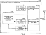
- FIG. 9 illustrates a first example of a configuration of a mobile station apparatus serving as the wireless communication apparatus 2 illustrated in FIG. 6 .
- the mobile station apparatus 200 includes a baseband signal processing section 201, an antenna 202, a wireless communication section 203, a CQI measuring section 204, a transmission power controlling section 205, and the relay determining section 22.
- the wireless communication section 203 includes a demodulating section 206.
- the transmission power controlling section 205 is given as an example of the parameter changing section 23.
- the baseband signal processing section 201 performs signal processing of a baseband signal for user data and control information transmitted between the mobile station apparatus 200 and a base station apparatus.
- the wireless communication section 203 transmits and receives user data and control information to/from the base station apparatus via the antenna 202.
- the demodulating section 206 demodulates the received wireless signal received from the base station apparatus.
- the CQI measuring section 204 measures the channel quality of the downlink channel from the base station apparatus to the mobile station apparatus 200 in accordance with the signal received by the wireless communication section 203.
- the transmission power controlling section 205 may generate the transmission power control signal for controlling transmission power of the downlink channel in accordance with the channel quality of the downlink channel, which has been measured by the CQI measuring section 204.
- the wireless communication section 203 transmits the transmission power control signal to the base station apparatus to control transmission power of the downlink channel.
- the relay determining section 22 determines whether the received wireless signal received from the base station apparatus has been relayed.
- the relay determining section 22 outputs the determination result signal indicating the result of the determination to the transmission power controlling section 205.
- the transmission power controlling section 205 may control transmission power of the base station apparatus by using the transmission power control signal so that transmission power of the base station apparatus in the downlink channel does not exceed a certain upper limit.
- the strength of transmission power in transmitting the signal from the base station apparatus using the downlink channel may be controlled in accordance with whether the received wireless signal received by the mobile station apparatus 200 has been relayed.
- FIG. 10 illustrates a second example of a configuration of a mobile station apparatus serving as the wireless communication apparatus 2 illustrated in FIG. 6 .
- the difference from the first example illustrated in FIG. 9 is that the mobile station apparatus 200 illustrated in FIG. 10 includes a CQI signal generating section 207 instead of the transmission power controlling section 205.
- the mobile station apparatus 200 includes the baseband signal processing section 201, the antenna 202, the wireless communication section 203, the CQI measuring section 204, the CQI signal generating section 207, and the relay determining section 22.
- the wireless communication section 203 includes a demodulating section 206.
- the CQI signal generating section 207 is given as an example of the parameter changing section 23.
- the CQI signal generating section 207 generates the CQI signal indicating the channel quality of the downlink channel, which has been measured by the CQI measuring section 204.
- the wireless communication section 203 transmits the CQI signal to the base station apparatus, and the base station apparatus controls transmission power in the downlink channel in accordance with the CQI signal.
- the relay determining section 22 may output the determination result signal indicating the result of the determination to the CQI signal generating section 207.
- the CQI signal generating section 207 restricts the value of the CQI signal transmitted to the base station apparatus so that the value of the CQI signal does not exceed a certain upper limit.
- the strength of transmission power in transmitting the signal from the base station apparatus using the downlink channel may be controlled in accordance with whether the received wireless signal received by the mobile station apparatus 200 has been relayed.
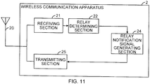
- FIG. 11 illustrates a third example of a confguration of the wireless communication apparatus 2 illustrated in FIG. 1 .
- the wireless communication apparatus 2 illustrated in FIG. 11 further includes a relay notification signal generating section 24, and a transmitting section 25.
- the wireless communication apparatus 2 includes the antenna 20, the receiving section 21, the relay determining section 22, the relay notification signal generating section 24, and the transmitting section 25.
- the relay notification signal generating section 24 generates a relay notification signal indicating that the wireless signal received from the wireless communication apparatus 3 has been relayed, in accordance with the determination result signal output from the relay determining section 22.
- the transmitting section 25 transmits the relay notification signal generated by the relay notification signal generating section 24 to the wireless communication apparatus 3, which is the transmission source of the received wireless signal.
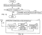
- FIG. 12 illustrates an example of an operation flow of a process performed by the wireless communication apparatus 2 illustrated in FIG. 11 .
- the receiving section 21 receives an incoming wireless signal via the antenna 20.
- the relay determining section 22 determines whether the received wireless signal is a relayed signal. When the received wireless signal is not a relayed signal ("No" in operation DB), the wireless communication apparatus 2 terminates the process.
- the relay notification signal generating section 24 In operation DC, when the received wireless signal is a relayed signal ("Yes" in operation DB), the relay notification signal generating section 24 generates the relay notification signal.
- the transmitting section 25 transmits the relay notification signal to the wireless communication apparatus 3, which is the transmission source of the received wireless signal.
- the wireless communication apparatus 2 may notify the wireless communication apparatus 3, which is the transmission source of the received wireless signal, of the fact that the wireless signal received from the wireless communication apparatus 3 has been relayed. Therefore, for example, the wireless communication apparatus 2 at the receiving side may detect whether communication from the wireless communication apparatus 3 to the wireless communication apparatus 2 has been relayed, and the wireless communication apparatus 3 at the transmitting side may change a communication parameter used in communication from the wireless communication apparatus 3 to the wireless communication apparatus 2.
- FIG. 13 illustrates an example of a configuration of the wireless communication apparatus 3 illustrated in FIG. 1 .
- the wireless communication apparatus 3 may receive the relay notification signal transmitted from the wireless communication apparatus 2 illustrated in FIG. 11 .
- the wireless communication apparatus 3 includes an antenna 30, a receiving section 31, a relay notification signal detecting section 32, and a parameter changing section 33.
- the receiving section 31 receives an incoming wireless signal via the antenna 30.
- the relay notification signal detecting section 32 detects, from the received wireless signal, the relay notification signal transmitted from the wireless communication apparatus 2.
- the parameter changing section 33 changes the communication parameter for wireless communication between the wireless communication apparatus 2, which is the transmission source of the relay notification signal, and the wireless communication apparatus 3 in accordance with whether the relay notification signal has been detected.
- any type of communication parameter may be used as long as the communication parameter is meaningful to be changed in accordance with whether the received wireless signal has been relayed.
- communication parameters to be changed by the parameter changing section 33 may include a parameter for determining whether to use MIMO transmission and a parameter indicating the strength of transmission power.
- the parameter changing section 33 uses, as in the foregoing discussion, a parameter used when the wireless communication apparatuses 2 and 3 directly communicate with each other as the communication parameter for wireless communication between the wireless communication apparatuses 2 and 3.
- the parameter changing section 33 uses, as in the foregoing discussion, the parameter used when communication between the wireless communication apparatuses 2 and 3 is relayed as the communication parameter between the wireless communication apparatus 2, which is the transmission source of the relay notification signal, and the wireless communication apparatus 3.
- the communication parameter to be changed by the parameter changing section 33 may be a communication parameter for wireless communication in which the wireless signal is transmitted from the wireless communication apparatus 2 to the wireless communication apparatus 3.
- the communication parameter to be changed by the parameter changing section 33 may be a communication parameter for wireless communication in which the wireless signal is transmitted from the wireless communication apparatus 3 to the wireless communication apparatus 2.
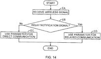
- FIG. 14 illustrates an example of an operation flow of a process performed by the wireless communication apparatus 3 illustrated in FIG. 13 .
- the receiving section 31 receives an incoming wireless signal via the antenna 30.
- the parameter changing section 33 determines whether the relay notification signal detecting section 32 has detected, from the received wireless signal, the relay notification signal transmitted from the wireless communication apparatus 2.
- the wireless communication apparatus 3 advances the process to operation EC.
- the wireless communication apparatus 3 advances the process to operation ED.
- the parameter changing section 33 uses, as the communication parameter for wireless communication between the wireless communication apparatuses 2 and 3, a parameter used when the wireless communication apparatuses 2 and 3 directly communicate with each other. Thereafter, the wireless communication apparatus 3 terminates the process.
- the parameter changing section 33 uses, as the communication parameter for wireless communication between the wireless communication apparatus 2, which is the transmission source of the relay notification signal, and the wireless communication apparatus 3, a parameter used when communication between the wireless communication apparatuses 2 and 3 is relayed. Thereafter, the wireless communication apparatus 3 terminates the process.
- the wireless communication apparatus 3 may change the communication parameter used in communication between the wireless communication apparatuses 2 and 3 in accordance with the result of detection, which has been performed by the wireless communication apparatus 2 at the receiving side, indicating whether communication from the wireless communication apparatus 3 to the wireless communication apparatus 2 has been relayed.
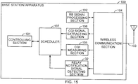
- FIG. 15 illustrates an example of a configuration of a base station apparatus serving as the wireless communication apparatus 3 illustrated in FIG. 13 .
- the base station apparatus 100 illustrated in FIG. 15 includes a relay notification signal detecting section 32 instead of the relay determining section 22.
- the base station apparatus 100 includes the controlling section 101, the baseband signal processing section 102, the antenna 103, and the wireless communication section 104.
- the base station apparatus 100 further includes the CQI measuring section 105, the CQI signal extracting section 106, the scheduler 107, and the relay notification signal detecting section 32.
- the base station apparatus 100 receives the relay notification signal from a mobile station apparatus serving as the wireless communication apparatus 2 illustrated in FIG. 11 .
- the relay notification signal detecting section 32 detects, from the wireless signal received by the wireless communication section 104, the relay notification signal transmitted from the mobile station apparatus.
- the scheduler 107 may restrict transmission power of the base station apparatus 100 to a certain upper limit or less.
- the scheduler 107 may control transmission power in transmitting the signal from the mobile station apparatus by using a transmission power control signal so that transmission power in transmitting the signal from the mobile station apparatus using the uplink channel does not exceed a certain upper limit.
- the scheduler 107 may determine not to perform MIMO transmission with the mobile station apparatus.
- the communication parameter for communication in the downlink may be changed in accordance with the result of detection, which has been performed by the mobile station apparatus, indicating whether the signal transmitted in the downlink has been relayed.
- the communication parameter for communication in an uplink may be changed in accordance with the result of detection, which has been performed by the mobile station apparatus, indicating whether the signal transmitted in the uplink has been relayed.
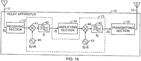
- FIG. 16 illustrates a first example of a configuration of the advice information adding section 13 of the relay apparatus 10. The difference from the example illustrated in FIG. 2 is that local oscillators 40 and 43, multipliers 41 and 44, and band-pass filters 42 and 45 are illustrated as a detailed configuration of the advice information adding section 13.
- the advice information adding section 13 adds, to the received wireless signal, information indicating that the received wireless signal has been relayed, by inverting the sign of the frequency of the received wireless signal, that is, by inverting the spectrum of the received wireless signal.
- the frequency of the carrier wave of the wireless signal received by the relay apparatus 10 is denoted by "fc".
- the advice information adding section 13 may include a frequency converter and a band-pass filter.
- the frequency converter converts the received wireless signal into a signal including a frequency component "-fc" which has the same frequency as, but whose sign is different from, the frequency fc of the carrier wave of the received wireless signal.
- the band-pass filter extracts a frequency component with a frequency of "fc" from an output signal of the frequency converter.
- the advice information adding section 13 includes, as the frequency converter, a first mixer including the local oscillator 40 and the multiplier 41, and a second mixer including the local oscillator 43 and the multiplier 44.
- the configuration illustrated in FIG. 16 is an example of the configuration of the frequency converter, and it is not intended to restrict the embodiment of the advice information adding section 13 to that discussed in the following discussion.
- the frequency converter may be realized in various configurations.
- the first mixer may be a part of the receiving section 12, and the second mixer may be a part of the transmitting section 15.
- the frequency of an intermediate frequency signal amplified by the amplifying section 14 is denoted by "fi".
- the local oscillator 40 generates a local signal with a frequency of "fc+fi”.
- the multiplier 41 multiplies the received wireless signal with a frequency of "fc” by the local signal output from the local oscillator 40, thereby converting the received wireless signal into a signal including a component with a frequency of "-fi" and a component with a frequency of "2fc+fi".
- the pass band of the band-pass filter 42 is the intermediate frequency "fi".
- the band-pass filter 42 extracts, from the output signal of the multiplier 41, an intermediate frequency signal with the frequency of "-fi".
- the amplifying section 14 amplifies the intermediate frequency signal, and inputs the amplified signal to the multiplier 44.
- the local oscillator 43 generates a local signal with a frequency of "fc-fi".
- the multiplier 44 multiplies the intermediate frequency signal with a frequency of "-fi” by the local signal output from the local oscillator 43, thereby converting the intermediate frequency signal into a signal including a component with a frequency of "-fc” and a component with a frequency of "fc-2fi".
- the pass band of the band-pass filter 45 is the frequency "fc" of the carrier wave.
- the band-pass filter 45 extracts, from the output signal of the multiplier 44, a carrier signal with the frequency of "-fc". In this manner, the advice information adding section 13 inverts the sign of the frequency of the received wireless signal. The signal whose sign of the frequency has been inverted is transmitted by the transmitting section 15.
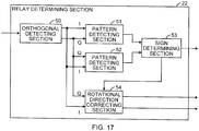
- FIG. 17 illustrates a first example of a configuration of the relay determining section 22.
- the relay determining section 22 determines whether the advice information has been added, to the received wireless signal received by the wireless communication apparatus 2, by the advice information adding section 13 illustrated in FIG. 16 .
- the relay determining section 22 includes an orthogonal detecting section 50, pattern detecting sections 51 and 52, a sign determining section 53, and a rotational direction correcting section 54.
- the orthogonal detecting section 50 applies orthogonal detection process to the received wireless signal received by the wireless communication apparatus 2, and generates an in-phase component signal (I component signal) and a quadrature-phase component signal (Q component signal).
- the pattern detecting section 51 calculates a correlation value between a certain pattern that is known to be included in the received wireless signal and a pattern of a symbol of a constellation point corresponding to the in-phase component signal and the quadrature-phase component signal output from the orthogonal detecting section 50.
- the pattern detecting section 51 may use, for example, a pilot signal or a reference signal as such a known pattern.
- the pattern detecting section 52 calculates a correlation value between the foregoing certain pattern and a pattern of a symbol corresponding to a signal obtained by inverting the rotational direction of the phase of the in-phase component signal and the quadrature-phase component signal output from the orthogonal detecting section 50.
- the sign determining section 53 determines whether the sign of the frequency of the carrier wave of the received wireless signal received by the wireless communication apparatus 2 has been inverted, that is, whether the received wireless signal has been relayed.
- the sign determining section 53 determines that the sign of the frequency of the carrier wave of the received wireless signal has not been inverted.
- the sign determining section 53 determines that the sign of the frequency of the carrier wave of the received wireless signal has been inverted.
- the sign determining section 53 outputs a determination result signal indicating whether the received wireless signal has been relayed.
- the rotational direction correcting section 54 corrects the rotational direction of the phase of the in-phase component signal and the quadrature-phase component signal output by the orthogonal detecting section 50.
- the rotational direction correcting section 54 simply outputs the in-phase component signal and the quadrature-phase component signal output by the orthogonal detecting section 50, without changing these signals.
- the rotational direction correcting section 54 Inverts the rotational direction of the phase of the in-phase component signal and the quadrature-phase component signal output by the orthogonal detecting section 50, and outputs these signals.
- the rotational direction correcting section 54 may invert the rotational direction of the phase of the in-phase component signal and the quadrature-phase component signal by, for example, exchanging the in-phase component and the quadrature-phase component of the input in-phase component signal and the input quadrature-phase component signal.
- the rotational direction correcting section 54 may invert the rotational direction of the phase of the in-phase component signal and the quadrature-phase component signal by, for example, inverting the value of either one of the input in-phase component signal and the input quadrature-phase component signal.
- the in-phase component signal and the quadrature-phase component signal output from the rotational direction correcting section 54 are supplied to the demodulating section that demodulates the received wireless signal received by the wireless communication apparatus 2.
- the demodulating section 108 when the wireless communication apparatus 2 is the base station apparatus 100 illustrated in FIG. 8 , the in-phase component signal and the quadrature-phase component signal output from the rotational direction correcting section 54 may be supplied to the demodulating section 108.
- the in-phase component signal and the quadrature-phase component signal output from the rotational direction correcting section 54 may be supplied to the demodulating section 206.
- information indicating that the wireless signal has been relayed may be added to the relayed wireless signal by inverting or not inverting the sign of the frequency of the carrier wave of the wireless signal. Even when the sign of the frequency of the carrier wave is inverted, the wireless resources of the wireless signal are not consumed.
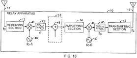
- FIG. 18 illustrates an illustrative example of a configuration of an advice information adding section 13 for a relay apparatus 10, which is not specifically claimed.
- the difference from the first example illustrated in FIG. 16 is that the relay apparatus 10 illustrated in FIG. 18 includes local oscillators 46 and 47 instead of the local oscillators 40 and 43, and further includes a signal adder 48.
- the relay apparatus 10 includes the antennas 11 and 16, the receiving section 12, the advice information adding section 13, the amplifying section 14, the transmitting section 15, the local oscillators 46 and 47, the multipliers 41 and 44, and the band-pass filters 42 and 45.
- the advice information adding section 13 includes the signal adder 48.
- the frequency of the carrier wave of the wireless signal received by the relay apparatus 10 is denoted by "fc”.
- the frequency of an intermediate frequency signal amplified by the amplifying section 14 is denoted by "fi”.
- the multiplier 41 multiplies the received wireless signal with a frequency of "fc” by the local signal with a frequency of "fc-fi” that has been generated by the local oscillator 46, thereby converting the received wireless signal into a signal including a component with a frequency of "fi” and a component with a frequency of "2fc-fi".
- the band-pass filter 42 extracts the intermediate frequency signal with the frequency of "fi" from the output signal of the multiplier 41.
- the signal adder 48 adds an advice signal indicating that the received wireless signal has been relayed by a relay apparatus to the intermediate frequency signal extracted by the band-pass filter 42.
- the signal adder 48 may add the advice signal by multiplexing a certain pattern with the intermediate frequency signal.
- the signal adder 48 may multiplex an advice signal of a certain pattern within a frequency band that has a negligible effect on the main signal.
- the signal adder 48 may multiplex an advice signal of a certain pattern by code spreading.
- the multiplier 44 multiplies the intermediate frequency signal, that includes the advice signal being multiplexed therewith, with a frequency of "fi" by a local signal, that has been generated by the local oscillator 47, with a frequency of "fc-fi", thereby converting the intermediate frequency signal into a signal including a component with a frequency of "fc” and a component with a frequency of "-fc+2fi".
- the band-pass filter 45 extracts the carrier signal with the frequency of "fc" from the output signal of the multiplier 44.
- FIG. 19 illustrates a second example of a configuration of the relay determining section 22.
- the relay determining section 22 determines whether the advice information, which indicates that the received wireless signal received by the wireless communication apparatus 2 has been relayed, has been added to the received wireless signal by the advice information adding section 13 illustrated in FIG. 18 .
- the relay determining section 22 includes an advice signal detecting section 55.
- the received wireless signal received by the wireless communication apparatus 2 is supplied to the advice signal detecting section 55 and the demodulating section that demodulates the received wireless signal received by the wireless communication apparatus 2, as it is or frequency-converted into the baseband frequency signal or the intermediate frequency signal.
- the demodulating section may be, for example, the demodulating section 108 illustrated in FIG. 8 or the demodulating section 206 illustrated in FIGs. 9 and 10 .
- the advice signal detecting section 55 detects whether the input received wireless signal includes the advice signal added by the signal adder 48 illustrated in FIG. 18 . When the input received wireless signal includes the advice signal, the advice signal detecting section 55 determines that the received wireless signal has been relayed. When the input received wireless signal does not include the advice signal, the advice signal detecting section 55 determines that the received wireless signal has not been relayed. When the advice signal has been multiplexed with the received wireless signal in a spread state by code spreading, the advice signal detecting section 55 may determine whether the received wireless signal includes the advice signal by using a correlator that calculates correlation with the spread code.
- information indicating that the received wireless signal has been relayed may be added to the relayed signal.
- FIG. 20 illustrates an example of a configuration of a positioning system 300 as an example of a communication system according to the present embodiment.
- the positioning system 300 includes positioning signal transmitting apparatuses 301A to 301C, the relay apparatus 10, and the wireless communication apparatus 2.
- the positioning signal transmitting apparatuses 301A to 301C may also be referred to as positioning signal transmitting apparatuses 301.
- the wireless communication apparatus 2 measures a delay time of each of positioning signals transmitted from the positioning signal transmitting apparatuses 301 at different locations, and, in accordance with the distances from these positioning signal transmitting apparatuses 301, measures the position of the wireless communication apparatus 2.
- the positioning system 300 may be a global positioning system (GPS) or an advanced forward link trilateration (AFLT) system.
- the positioning signal transmitting apparatuses 301 are GPS satellites.
- the positioning signal transmitting apparatuses 301 are base station apparatuses.
- the GPS and AFLT systems are examples of the positioning system 300, and the present discussion does not intended to restrict the embodiment of the positioning system 300 to these specific systems.
- the positioning system 300 may be any type of positioning system as long as it is a system that measures the position of a positioning target in accordance with a delay time of each of positioning signals received from multiple positioning signal transmitting apparatuses.
- the relay apparatus 10 relays positioning signals transmitted from the positioning signal transmitting apparatuses 301. That is, the relay apparatus 10 amplifies and transmits wireless signals received from the positioning signal transmitting apparatuses 301.
- the configuration of the relay apparatus 10 may be similar to the foregoing configuration discussed with reference to FIG. 2 .
- the delay time that occurs to the positioning signal relayed by the relay apparatus is different from the delay time that occurs when the wireless communication apparatus 2 directly receives the positioning signal from one of the positioning signal transmitting apparatuses 301. Therefore, when the positioning signal is relayed by the relay apparatus, the measurement accuracy of the measurement result obtained by the wireless communication apparatus 2 is degraded. Thus, the wireless communication apparatus 2 discussed below determines whether the positioning signal has been relayed.
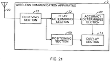
- FIG. 21 illustrates an example of a configuration of the wireless communication apparatus 2 illustrated in FIG. 20 .
- the wireless communication apparatus 2 illustrated in FIG. 21 further includes a positioning section 60, a display section 61, and an accuracy determining section 62.
- the wireless communication apparatus 2 includes the antenna 20, the receiving section 21, the relay determining section 22, the positioning section 60, the display section 61, and the accuracy determining section 62.
- the positioning section 60 measures the position of the wireless communication apparatus 2 in accordance with a delay time of each of the positioning signals received by the receiving section 21 from the positioning signal transmitting apparatuses 301.
- the display section 61 outputs the result of the measurement of the position of the wireless communication apparatus 2 in a form that the user of the wireless communication apparatus 2 may view and recognize.
- the accuracy determining section 62 receives the determination result signal from the relay determining section 22.
- the accuracy determining section 62 determines whether the accuracy of positioning performed by the positioning section 60 is good or poor, in accordance with whether the positioning signals have been relayed. That is, when the positioning signals have not been relayed, the accuracy determining section 62 determines that the accuracy of positioning performed by the positioning section 60 is normal. When the positioning signals have been relayed, the accuracy determining section 62 determines that the accuracy of positioning performed by the positioning section 60 may be poor.
- the result of the determination performed by the accuracy determining section 62 is presented to the user by using the display section 61.
- the display section 61 may output the result of the determination in a form that indicates whether the accuracy is good or poor. Alternatively, when the positioning signals have been relayed, a warning that indicates that the positioning signals have been relayed may be simply output.
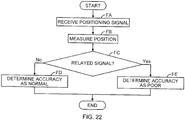
- FIG. 22 illustrates an example of an operation flow of a process performed by the wireless communication apparatus 2 illustrated in FIG. 21 .
- the receiving section 21 receives an incoming positioning signal via the antenna 20.
- the positioning section 60 measures the position of the wireless communication apparatus 2 in accordance with a delay time of each of the positioning signals received by the receiving section 21 from the positioning signal transmitting apparatuses 301.
- the display section 61 outputs the result of the positioning of the wireless communication apparatus 2 in a form that the user of the wireless communication apparatus 2 may view and recognize.
- the relay determining section 22 determines whether the positioning signals received in operation FA have been relayed. When the positioning signals have not been relayed ("No” in operation FC), the wireless communication apparatus 2 advances the process to operation FD. When the positioning signals have been relayed ("Yes” in operation FC), the wireless communication apparatus 2 advances the process to operation FE.
- the accuracy determining section 62 determines that the accuracy of positioning performed by the positioning section 60 is normal.
- the display section 61 outputs the result of the determination performed by the accuracy determining section 62. Thereafter, the wireless communication apparatus 2 terminates the process.
- the accuracy determining section 62 determines that the accuracy of positioning performed by the positioning section 60 may be poor.
- the display section 61 outputs the result of the determination performed by the accuracy determining section 62. Thereafter, the wireless communication apparatus 2 terminates the process.
- whether the accuracy of the measurement result is good or poor may be determined in accordance with whether positioning signals received by the wireless communication apparatus 2 in the positioning system 300 have been relayed.
Landscapes
- Engineering & Computer Science (AREA)
- Computer Networks & Wireless Communication (AREA)
- Signal Processing (AREA)
- Mobile Radio Communication Systems (AREA)
- Radio Relay Systems (AREA)
Claims (5)
- Drahtloses Datenübertragungsverfahren, ausgeführt von einem drahtlosen Datenübertragungssystem, das eine Relaisvorrichtung (10), eine erste drahtlose Datenübertragungsvorrichtung (3) und eine zweite drahtlose Datenübertragungsvorrichtung (2) aufweist, wobei das drahtlose Datenübertragungsverfahren umfasst:Hinzufügen von Benachrichtigungsinformationen zu dem empfangenen drahtlosen Signal mithilfe der Relaisvorrichtung (10) beim Empfangen eines drahtlosen Signals von der ersten drahtlosen Datenübertragungsvorrichtung (3), wobei die Benachrichtigungsinformationen anzeigen, dass das drahtlose Signal weitergeleitet wurde;Übertragen des drahtlosen Signals, dem die Benachrichtigungsinformationen hinzugefügt wurden, mithilfe der Relaisvorrichtung (10) zu der zweiten drahtlosen Datenübertragungsvorrichtung (2); undErkennen der Benachrichtigungsinformationen mithilfe der zweiten drahtlosen Datenübertragungsvorrichtung (2), um festzustellen, ob das drahtlose Signal weitergeleitet wurde,wobei die Relaisvorrichtung (10) die Benachrichtigungsinformationen durch Umkehren eines Vorzeichens einer Frequenz des drahtlosen Signals hinzufügt.
- Drahtloses Datenübertragungsverfahren nach Anspruch 1, das ferner umfasst:Ändern, mithilfe der zweiten drahtlosen Datenübertragungsvorrichtung (2), eines Datenübertragungsparameters zur drahtlosen Datenübertragung zwischen der zweiten drahtlosen Datenübertragungsvorrichtung (2) und der ersten drahtlosen Datenübertragungsvorrichtung (3) in Übereinstimmung damit, ob das drahtlose Signal weitergeleitet wurde.
- Drahtloses Datenübertragungsverfahren nach Anspruch 1, das ferner umfasst:Benachrichtigen der ersten drahtlosen Datenübertragungsvorrichtung (3) mithilfe der zweiten drahtlosen Datenübertragungsvorrichtung (2), dass das drahtlose Signal weitergeleitet wurde; undÄndern, mithilfe der ersten drahtlosen Datenübertragungsvorrichtung (3), eines Datenübertragungsparameters zur drahtlosen Datenübertragung zwischen der zweiten drahtlosen Datenübertragungsvorrichtung (2) und der ersten drahtlosen Datenübertragungsvorrichtung (3) in Übereinstimmung damit, ob das drahtlose Signal weitergeleitet wurde.
- Drahtloses Datenübertragungsverfahren nach Anspruch 1, wobei das drahtlose Signal ein Positionierungssignal ist, wobei das drahtlose Datenübertragungsverfahren ferner umfasst:Feststellen einer Genauigkeit einer Positionierung auf Grundlage des Positionierungssignals mithilfe der zweiten drahtlosen Datenübertragungsvorrichtung (2), in Übereinstimmung damit, ob das drahtlose Signal weitergeleitet wurde.
- Relaisvorrichtung (10) zum Weiterleiten eines drahtlosen Signals, wobei die Relaisvorrichtung (10) umfasst:einen Empfangsabschnitt (12), der derart ausgestaltet ist, dass er das drahtlose Signal empfängt;einen Verstärkungsabschnitt (14), der derart ausgestaltet ist, dass er das empfangene drahtlose Signal verstärkt;einen Übertragungsabschnitt (15), der derart ausgestaltet ist, dass er das verstärkte drahtlose Signal überträgt; undeinen Benachrichtigungsinformations-Hinzufügungsabschnitt (13), der derart ausgestaltet ist,dass er dem drahtlosen Signal Benachrichtigungsinformationen hinzufügt, die anzeigen, dass das drahtlose Signal weitergeleitet wurde, wobei der Benachrichtigungsinformations-Hinzufügungsabschnitt (13) die Benachrichtigungsinformationen durch Umkehren eines Vorzeichens einer Frequenz des drahtlosen Signals hinzufügt.
Applications Claiming Priority (1)
| Application Number | Priority Date | Filing Date | Title |
|---|---|---|---|
| JP2009200223A JP5428659B2 (ja) | 2009-08-31 | 2009-08-31 | 無線通信装置 |
Publications (3)
| Publication Number | Publication Date |
|---|---|
| EP2290840A2 EP2290840A2 (de) | 2011-03-02 |
| EP2290840A3 EP2290840A3 (de) | 2014-03-26 |
| EP2290840B1 true EP2290840B1 (de) | 2017-06-21 |
Family
ID=43216528
Family Applications (1)
| Application Number | Title | Priority Date | Filing Date |
|---|---|---|---|
| EP10174428.2A Not-in-force EP2290840B1 (de) | 2009-08-31 | 2010-08-27 | Drahtloses Kommunikationsverfahren und Relaisvorrichtung |
Country Status (3)
| Country | Link |
|---|---|
| US (1) | US8483607B2 (de) |
| EP (1) | EP2290840B1 (de) |
| JP (1) | JP5428659B2 (de) |
Families Citing this family (3)
| Publication number | Priority date | Publication date | Assignee | Title |
|---|---|---|---|---|
| JP4920780B1 (ja) * | 2010-10-08 | 2012-04-18 | 株式会社エヌ・ティ・ティ・ドコモ | 基地局及び方法 |
| US9191097B2 (en) * | 2012-12-20 | 2015-11-17 | Intel Corporation | Techniques for transmitting data via relay communication links |
| US20150285904A1 (en) * | 2014-04-04 | 2015-10-08 | Texas Instruments Incorporated | Antenna configuration for parking assist radar |
Family Cites Families (4)
| Publication number | Priority date | Publication date | Assignee | Title |
|---|---|---|---|---|
| JP3900668B2 (ja) * | 1998-04-15 | 2007-04-04 | 松下電器産業株式会社 | 無線ネットワークシステム |
| US7062224B2 (en) * | 2002-01-09 | 2006-06-13 | Qualcomm Incorporated | Method and system for identifying and monitoring repeater traffic in a code division multiple access system |
| US7295808B2 (en) * | 2002-09-05 | 2007-11-13 | Soliman Samir S | Method of and system for calibrating a repeater |
| JP4486665B2 (ja) | 2007-08-24 | 2010-06-23 | ソフトバンクBb株式会社 | 無線中継装置及び無線中継装置の制御方法 |
-
2009
- 2009-08-31 JP JP2009200223A patent/JP5428659B2/ja not_active Expired - Fee Related
-
2010
- 2010-08-09 US US12/852,949 patent/US8483607B2/en not_active Expired - Fee Related
- 2010-08-27 EP EP10174428.2A patent/EP2290840B1/de not_active Not-in-force
Also Published As
| Publication number | Publication date |
|---|---|
| US8483607B2 (en) | 2013-07-09 |
| JP5428659B2 (ja) | 2014-02-26 |
| US20110053497A1 (en) | 2011-03-03 |
| EP2290840A2 (de) | 2011-03-02 |
| JP2011055100A (ja) | 2011-03-17 |
| EP2290840A3 (de) | 2014-03-26 |
Similar Documents
| Publication | Publication Date | Title |
|---|---|---|
| US7340248B2 (en) | Calibration apparatus | |
| CN101958734B (zh) | 无线覆盖整体解决方案 | |
| US20100329311A1 (en) | Uplink signal detection in rf repeaters | |
| JPWO2011077862A1 (ja) | 中継装置、中継システム、中継方法、無線通信システム、プログラム | |
| EP2101418A1 (de) | Verfahren zum Steuern der Interferenz, die von einer Mobilstation auf Nachbarbasisstationen erzeugt wird | |
| WO2015045697A1 (ja) | 無線通信装置、チャネル推定方法及び信号中継方法 | |
| KR100934832B1 (ko) | 이동체 통신 시스템, 이동체 통신 시스템에 있어서의 이동단말, 그 제어 프로그램 및 이동체 통신 시스템에 있어서의동기 확립 판정 방법 | |
| CN101959261B (zh) | 高速移动场景下的信号选择方法和设备 | |
| EP2290840B1 (de) | Drahtloses Kommunikationsverfahren und Relaisvorrichtung | |
| EP2919553B1 (de) | Dezentralisierte basisstation und signalrückgabeverfahren und vorrichtung dafür | |
| JP3583304B2 (ja) | 通信端末装置、基地局装置及び送信アンテナ切替方法 | |
| US8285234B2 (en) | Mobile station apparatus | |
| JP2010062997A (ja) | 無線通信装置 | |
| JP5408204B2 (ja) | 基地局装置 | |
| JPH08168075A (ja) | 移動無線装置 | |
| JP2000165290A (ja) | スペクトル拡散通信方法およびスペクトル拡散通信装置 | |
| JP2011188316A (ja) | 周波数ホッピング無線通信装置およびその周波数ホッピング方法ならびに送信装置および受信装置 | |
| US20250293757A1 (en) | Receiver beamforming | |
| JP2001036442A (ja) | 無線通信システム、無線送信装置および無線受信装置 | |
| EP1895695A1 (de) | Drahtloser empfänger | |
| EP1052865A1 (de) | Basisstation und verfahren zur sendeleistungssteuerung | |
| JP4010372B2 (ja) | 無線中継増幅装置 | |
| KR100926827B1 (ko) | 이동통신 시스템에서 다중 pn을 제거하는 중계기 및 그방법 | |
| JP5095503B2 (ja) | 無線中継増幅装置 | |
| JP2007311839A (ja) | デジタル無線装置 |
Legal Events
| Date | Code | Title | Description |
|---|---|---|---|
| PUAI | Public reference made under article 153(3) epc to a published international application that has entered the european phase |
Free format text: ORIGINAL CODE: 0009012 |
|
| AK | Designated contracting states |
Kind code of ref document: A2 Designated state(s): AL AT BE BG CH CY CZ DE DK EE ES FI FR GB GR HR HU IE IS IT LI LT LU LV MC MK MT NL NO PL PT RO SE SI SK SM TR |
|
| AX | Request for extension of the european patent |
Extension state: BA ME RS |
|
| PUAL | Search report despatched |
Free format text: ORIGINAL CODE: 0009013 |
|
| AK | Designated contracting states |
Kind code of ref document: A3 Designated state(s): AL AT BE BG CH CY CZ DE DK EE ES FI FR GB GR HR HU IE IS IT LI LT LU LV MC MK MT NL NO PL PT RO SE SI SK SM TR |
|
| AX | Request for extension of the european patent |
Extension state: BA ME RS |
|
| RIC1 | Information provided on ipc code assigned before grant |
Ipc: H04B 7/155 20060101ALI20140219BHEP Ipc: H04B 7/15 20060101AFI20140219BHEP |
|
| 17P | Request for examination filed |
Effective date: 20140414 |
|
| RBV | Designated contracting states (corrected) |
Designated state(s): AL AT BE BG CH CY CZ DE DK EE ES FI FR GB GR HR HU IE IS IT LI LT LU LV MC MK MT NL NO PL PT RO SE SI SK SM TR |
|
| GRAP | Despatch of communication of intention to grant a patent |
Free format text: ORIGINAL CODE: EPIDOSNIGR1 |
|
| RIC1 | Information provided on ipc code assigned before grant |
Ipc: H04B 7/15 20060101AFI20161209BHEP Ipc: H04B 7/155 20060101ALI20161209BHEP |
|
| INTG | Intention to grant announced |
Effective date: 20170111 |
|
| GRAS | Grant fee paid |
Free format text: ORIGINAL CODE: EPIDOSNIGR3 |
|
| GRAA | (expected) grant |
Free format text: ORIGINAL CODE: 0009210 |
|
| AK | Designated contracting states |
Kind code of ref document: B1 Designated state(s): AL AT BE BG CH CY CZ DE DK EE ES FI FR GB GR HR HU IE IS IT LI LT LU LV MC MK MT NL NO PL PT RO SE SI SK SM TR |
|
| REG | Reference to a national code |
Ref country code: GB Ref legal event code: FG4D |
|
| REG | Reference to a national code |
Ref country code: CH Ref legal event code: EP |
|
| REG | Reference to a national code |
Ref country code: IE Ref legal event code: FG4D |
|
| REG | Reference to a national code |
Ref country code: AT Ref legal event code: REF Ref document number: 903793 Country of ref document: AT Kind code of ref document: T Effective date: 20170715 |
|
| REG | Reference to a national code |
Ref country code: FR Ref legal event code: PLFP Year of fee payment: 8 |
|
| REG | Reference to a national code |
Ref country code: DE Ref legal event code: R096 Ref document number: 602010043076 Country of ref document: DE |
|
| REG | Reference to a national code |
Ref country code: NL Ref legal event code: MP Effective date: 20170621 |
|
| PG25 | Lapsed in a contracting state [announced via postgrant information from national office to epo] |
Ref country code: GR Free format text: LAPSE BECAUSE OF FAILURE TO SUBMIT A TRANSLATION OF THE DESCRIPTION OR TO PAY THE FEE WITHIN THE PRESCRIBED TIME-LIMIT Effective date: 20170922 Ref country code: NO Free format text: LAPSE BECAUSE OF FAILURE TO SUBMIT A TRANSLATION OF THE DESCRIPTION OR TO PAY THE FEE WITHIN THE PRESCRIBED TIME-LIMIT Effective date: 20170921 Ref country code: FI Free format text: LAPSE BECAUSE OF FAILURE TO SUBMIT A TRANSLATION OF THE DESCRIPTION OR TO PAY THE FEE WITHIN THE PRESCRIBED TIME-LIMIT Effective date: 20170621 Ref country code: LT Free format text: LAPSE BECAUSE OF FAILURE TO SUBMIT A TRANSLATION OF THE DESCRIPTION OR TO PAY THE FEE WITHIN THE PRESCRIBED TIME-LIMIT Effective date: 20170621 Ref country code: HR Free format text: LAPSE BECAUSE OF FAILURE TO SUBMIT A TRANSLATION OF THE DESCRIPTION OR TO PAY THE FEE WITHIN THE PRESCRIBED TIME-LIMIT Effective date: 20170621 |
|
| PGFP | Annual fee paid to national office [announced via postgrant information from national office to epo] |
Ref country code: GB Payment date: 20170704 Year of fee payment: 8 Ref country code: FR Payment date: 20170725 Year of fee payment: 8 Ref country code: DE Payment date: 20170802 Year of fee payment: 8 |
|
| REG | Reference to a national code |
Ref country code: LT Ref legal event code: MG4D |
|
| REG | Reference to a national code |
Ref country code: AT Ref legal event code: MK05 Ref document number: 903793 Country of ref document: AT Kind code of ref document: T Effective date: 20170621 |
|
| PG25 | Lapsed in a contracting state [announced via postgrant information from national office to epo] |
Ref country code: SE Free format text: LAPSE BECAUSE OF FAILURE TO SUBMIT A TRANSLATION OF THE DESCRIPTION OR TO PAY THE FEE WITHIN THE PRESCRIBED TIME-LIMIT Effective date: 20170621 Ref country code: BG Free format text: LAPSE BECAUSE OF FAILURE TO SUBMIT A TRANSLATION OF THE DESCRIPTION OR TO PAY THE FEE WITHIN THE PRESCRIBED TIME-LIMIT Effective date: 20170921 Ref country code: LV Free format text: LAPSE BECAUSE OF FAILURE TO SUBMIT A TRANSLATION OF THE DESCRIPTION OR TO PAY THE FEE WITHIN THE PRESCRIBED TIME-LIMIT Effective date: 20170621 Ref country code: NL Free format text: LAPSE BECAUSE OF FAILURE TO SUBMIT A TRANSLATION OF THE DESCRIPTION OR TO PAY THE FEE WITHIN THE PRESCRIBED TIME-LIMIT Effective date: 20170621 |
|
| PG25 | Lapsed in a contracting state [announced via postgrant information from national office to epo] |
Ref country code: CZ Free format text: LAPSE BECAUSE OF FAILURE TO SUBMIT A TRANSLATION OF THE DESCRIPTION OR TO PAY THE FEE WITHIN THE PRESCRIBED TIME-LIMIT Effective date: 20170621 Ref country code: RO Free format text: LAPSE BECAUSE OF FAILURE TO SUBMIT A TRANSLATION OF THE DESCRIPTION OR TO PAY THE FEE WITHIN THE PRESCRIBED TIME-LIMIT Effective date: 20170621 Ref country code: SK Free format text: LAPSE BECAUSE OF FAILURE TO SUBMIT A TRANSLATION OF THE DESCRIPTION OR TO PAY THE FEE WITHIN THE PRESCRIBED TIME-LIMIT Effective date: 20170621 Ref country code: AT Free format text: LAPSE BECAUSE OF FAILURE TO SUBMIT A TRANSLATION OF THE DESCRIPTION OR TO PAY THE FEE WITHIN THE PRESCRIBED TIME-LIMIT Effective date: 20170621 Ref country code: EE Free format text: LAPSE BECAUSE OF FAILURE TO SUBMIT A TRANSLATION OF THE DESCRIPTION OR TO PAY THE FEE WITHIN THE PRESCRIBED TIME-LIMIT Effective date: 20170621 |
|
| PG25 | Lapsed in a contracting state [announced via postgrant information from national office to epo] |
Ref country code: IT Free format text: LAPSE BECAUSE OF FAILURE TO SUBMIT A TRANSLATION OF THE DESCRIPTION OR TO PAY THE FEE WITHIN THE PRESCRIBED TIME-LIMIT Effective date: 20170621 Ref country code: IS Free format text: LAPSE BECAUSE OF FAILURE TO SUBMIT A TRANSLATION OF THE DESCRIPTION OR TO PAY THE FEE WITHIN THE PRESCRIBED TIME-LIMIT Effective date: 20171021 Ref country code: SM Free format text: LAPSE BECAUSE OF FAILURE TO SUBMIT A TRANSLATION OF THE DESCRIPTION OR TO PAY THE FEE WITHIN THE PRESCRIBED TIME-LIMIT Effective date: 20170621 Ref country code: PL Free format text: LAPSE BECAUSE OF FAILURE TO SUBMIT A TRANSLATION OF THE DESCRIPTION OR TO PAY THE FEE WITHIN THE PRESCRIBED TIME-LIMIT Effective date: 20170621 Ref country code: ES Free format text: LAPSE BECAUSE OF FAILURE TO SUBMIT A TRANSLATION OF THE DESCRIPTION OR TO PAY THE FEE WITHIN THE PRESCRIBED TIME-LIMIT Effective date: 20170621 |
|
| REG | Reference to a national code |
Ref country code: DE Ref legal event code: R097 Ref document number: 602010043076 Country of ref document: DE |
|
| REG | Reference to a national code |
Ref country code: CH Ref legal event code: PL |
|
| PG25 | Lapsed in a contracting state [announced via postgrant information from national office to epo] |
Ref country code: MC Free format text: LAPSE BECAUSE OF FAILURE TO SUBMIT A TRANSLATION OF THE DESCRIPTION OR TO PAY THE FEE WITHIN THE PRESCRIBED TIME-LIMIT Effective date: 20170621 |
|
| PLBE | No opposition filed within time limit |
Free format text: ORIGINAL CODE: 0009261 |
|
| STAA | Information on the status of an ep patent application or granted ep patent |
Free format text: STATUS: NO OPPOSITION FILED WITHIN TIME LIMIT |
|
| PG25 | Lapsed in a contracting state [announced via postgrant information from national office to epo] |
Ref country code: CH Free format text: LAPSE BECAUSE OF NON-PAYMENT OF DUE FEES Effective date: 20170831 Ref country code: DK Free format text: LAPSE BECAUSE OF FAILURE TO SUBMIT A TRANSLATION OF THE DESCRIPTION OR TO PAY THE FEE WITHIN THE PRESCRIBED TIME-LIMIT Effective date: 20170621 Ref country code: LI Free format text: LAPSE BECAUSE OF NON-PAYMENT OF DUE FEES Effective date: 20170831 |
|
| 26N | No opposition filed |
Effective date: 20180322 |
|
| REG | Reference to a national code |
Ref country code: IE Ref legal event code: MM4A |
|
| REG | Reference to a national code |
Ref country code: BE Ref legal event code: MM Effective date: 20170831 |
|
| PG25 | Lapsed in a contracting state [announced via postgrant information from national office to epo] |
Ref country code: LU Free format text: LAPSE BECAUSE OF NON-PAYMENT OF DUE FEES Effective date: 20170827 |
|
| PG25 | Lapsed in a contracting state [announced via postgrant information from national office to epo] |
Ref country code: IE Free format text: LAPSE BECAUSE OF NON-PAYMENT OF DUE FEES Effective date: 20170827 |
|
| PG25 | Lapsed in a contracting state [announced via postgrant information from national office to epo] |
Ref country code: BE Free format text: LAPSE BECAUSE OF NON-PAYMENT OF DUE FEES Effective date: 20170831 Ref country code: SI Free format text: LAPSE BECAUSE OF FAILURE TO SUBMIT A TRANSLATION OF THE DESCRIPTION OR TO PAY THE FEE WITHIN THE PRESCRIBED TIME-LIMIT Effective date: 20170621 |
|
| PG25 | Lapsed in a contracting state [announced via postgrant information from national office to epo] |
Ref country code: MT Free format text: LAPSE BECAUSE OF NON-PAYMENT OF DUE FEES Effective date: 20170827 |
|
| REG | Reference to a national code |
Ref country code: DE Ref legal event code: R119 Ref document number: 602010043076 Country of ref document: DE |
|
| GBPC | Gb: european patent ceased through non-payment of renewal fee |
Effective date: 20180827 |
|
| PG25 | Lapsed in a contracting state [announced via postgrant information from national office to epo] |
Ref country code: HU Free format text: LAPSE BECAUSE OF FAILURE TO SUBMIT A TRANSLATION OF THE DESCRIPTION OR TO PAY THE FEE WITHIN THE PRESCRIBED TIME-LIMIT; INVALID AB INITIO Effective date: 20100827 |
|
| PG25 | Lapsed in a contracting state [announced via postgrant information from national office to epo] |
Ref country code: DE Free format text: LAPSE BECAUSE OF NON-PAYMENT OF DUE FEES Effective date: 20190301 |
|
| PG25 | Lapsed in a contracting state [announced via postgrant information from national office to epo] |
Ref country code: FR Free format text: LAPSE BECAUSE OF NON-PAYMENT OF DUE FEES Effective date: 20180831 |
|
| PG25 | Lapsed in a contracting state [announced via postgrant information from national office to epo] |
Ref country code: CY Free format text: LAPSE BECAUSE OF NON-PAYMENT OF DUE FEES Effective date: 20170621 Ref country code: GB Free format text: LAPSE BECAUSE OF NON-PAYMENT OF DUE FEES Effective date: 20180827 |
|
| PG25 | Lapsed in a contracting state [announced via postgrant information from national office to epo] |
Ref country code: MK Free format text: LAPSE BECAUSE OF FAILURE TO SUBMIT A TRANSLATION OF THE DESCRIPTION OR TO PAY THE FEE WITHIN THE PRESCRIBED TIME-LIMIT Effective date: 20170621 |
|
| PG25 | Lapsed in a contracting state [announced via postgrant information from national office to epo] |
Ref country code: TR Free format text: LAPSE BECAUSE OF FAILURE TO SUBMIT A TRANSLATION OF THE DESCRIPTION OR TO PAY THE FEE WITHIN THE PRESCRIBED TIME-LIMIT Effective date: 20170621 |
|
| PG25 | Lapsed in a contracting state [announced via postgrant information from national office to epo] |
Ref country code: PT Free format text: LAPSE BECAUSE OF FAILURE TO SUBMIT A TRANSLATION OF THE DESCRIPTION OR TO PAY THE FEE WITHIN THE PRESCRIBED TIME-LIMIT Effective date: 20170621 |
|
| PG25 | Lapsed in a contracting state [announced via postgrant information from national office to epo] |
Ref country code: AL Free format text: LAPSE BECAUSE OF FAILURE TO SUBMIT A TRANSLATION OF THE DESCRIPTION OR TO PAY THE FEE WITHIN THE PRESCRIBED TIME-LIMIT Effective date: 20170621 |