EP2290785B1 - Stromsparende unterbrechungsfreie Netzinteraktive Stromversorgung - Google Patents
Stromsparende unterbrechungsfreie Netzinteraktive Stromversorgung Download PDFInfo
- Publication number
- EP2290785B1 EP2290785B1 EP20100162823 EP10162823A EP2290785B1 EP 2290785 B1 EP2290785 B1 EP 2290785B1 EP 20100162823 EP20100162823 EP 20100162823 EP 10162823 A EP10162823 A EP 10162823A EP 2290785 B1 EP2290785 B1 EP 2290785B1
- Authority
- EP
- European Patent Office
- Prior art keywords
- power
- switch
- full
- line interactive
- rechargeable battery
- Prior art date
- Legal status (The legal status is an assumption and is not a legal conclusion. Google has not performed a legal analysis and makes no representation as to the accuracy of the status listed.)
- Active
Links
Images


Classifications
-
- H—ELECTRICITY
- H02—GENERATION; CONVERSION OR DISTRIBUTION OF ELECTRIC POWER
- H02J—CIRCUIT ARRANGEMENTS OR SYSTEMS FOR SUPPLYING OR DISTRIBUTING ELECTRIC POWER; SYSTEMS FOR STORING ELECTRIC ENERGY
- H02J9/00—Circuit arrangements for emergency or stand-by power supply, e.g. for emergency lighting
- H02J9/04—Circuit arrangements for emergency or stand-by power supply, e.g. for emergency lighting in which the distribution system is disconnected from the normal source and connected to a standby source
- H02J9/06—Circuit arrangements for emergency or stand-by power supply, e.g. for emergency lighting in which the distribution system is disconnected from the normal source and connected to a standby source with automatic change-over, e.g. UPS systems
- H02J9/062—Circuit arrangements for emergency or stand-by power supply, e.g. for emergency lighting in which the distribution system is disconnected from the normal source and connected to a standby source with automatic change-over, e.g. UPS systems for AC powered loads
-
- Y—GENERAL TAGGING OF NEW TECHNOLOGICAL DEVELOPMENTS; GENERAL TAGGING OF CROSS-SECTIONAL TECHNOLOGIES SPANNING OVER SEVERAL SECTIONS OF THE IPC; TECHNICAL SUBJECTS COVERED BY FORMER USPC CROSS-REFERENCE ART COLLECTIONS [XRACs] AND DIGESTS
- Y02—TECHNOLOGIES OR APPLICATIONS FOR MITIGATION OR ADAPTATION AGAINST CLIMATE CHANGE
- Y02B—CLIMATE CHANGE MITIGATION TECHNOLOGIES RELATED TO BUILDINGS, e.g. HOUSING, HOUSE APPLIANCES OR RELATED END-USER APPLICATIONS
- Y02B70/00—Technologies for an efficient end-user side electric power management and consumption
- Y02B70/30—Systems integrating technologies related to power network operation and communication or information technologies for improving the carbon footprint of the management of residential or tertiary loads, i.e. smart grids as climate change mitigation technology in the buildings sector, including also the last stages of power distribution and the control, monitoring or operating management systems at local level
-
- Y—GENERAL TAGGING OF NEW TECHNOLOGICAL DEVELOPMENTS; GENERAL TAGGING OF CROSS-SECTIONAL TECHNOLOGIES SPANNING OVER SEVERAL SECTIONS OF THE IPC; TECHNICAL SUBJECTS COVERED BY FORMER USPC CROSS-REFERENCE ART COLLECTIONS [XRACs] AND DIGESTS
- Y04—INFORMATION OR COMMUNICATION TECHNOLOGIES HAVING AN IMPACT ON OTHER TECHNOLOGY AREAS
- Y04S—SYSTEMS INTEGRATING TECHNOLOGIES RELATED TO POWER NETWORK OPERATION, COMMUNICATION OR INFORMATION TECHNOLOGIES FOR IMPROVING THE ELECTRICAL POWER GENERATION, TRANSMISSION, DISTRIBUTION, MANAGEMENT OR USAGE, i.e. SMART GRIDS
- Y04S20/00—Management or operation of end-user stationary applications or the last stages of power distribution; Controlling, monitoring or operating thereof
- Y04S20/20—End-user application control systems
Definitions
- the present invention is related to an uninterruptible power system (UPS), and more particularly to a power-saving line interactive UPS.
- UPS uninterruptible power system
- a conventional method and an apparatus for providing battery charging in a backup power system have been disclosed in US Patent No. 5,302,858 , which can be briefly described as follows.
- a battery in a back-up power system is charged during the time that power is available from the main AC power system by utilizing the main power transformer and the main inverter.
- an AC voltage appears across the primary of the transformer, which is connected to the inverter.
- Switches in the bridge inverter are turned on for a relatively brief period of time to short the primary of the transformer causing current through the leakage inductances of the transformer to rapidly build up.
- the inductances When the switching devices are turned off, the inductances induce a current to continue to flow from the primary into the inverter through anti-parallel diodes, normally back biased by the voltage from the battery, into the battery thereby charging the battery with the energy stored in the transformer inductances.
- the inverter current reaches zero when the energy stored in the inductance is fully discharged.
- the cycle may be repeated by turning on the switching devices in the inverter bridge at periodic points in time, allowing the current in the inverter to dwell periodically at zero, or by immediately turning on the switching devices again when the current into the inverter reaches zero.
- a conventional line interactive UPS has a power switch set (50), a low-frequency transformer (51), a full-bridge switching circuit (52), a main controller (53), a charge and discharge mode controller (54) and a rechargeable battery (55).
- the power switch set (50) is serially connected between an AC power supply and a load and determines if the AC power supply supplies power to the load.
- the low-frequency transformer (51) has two windings (511a, 511b). One of the windings (511a) is connected to the load and connected to the AC power supply through the power switch set (50).
- the full-bridge switching circuit (52) has two half-bridge switching circuits (521, 522). Serially connected nodes of the two half-bridge switching circuits (521, 522) are connected to the other winding (511b) of the low-frequency transformer (51).
- the main controller (53) is connected to the power switch set (50).
- the charge and discharge mode controller (54) is connected to the main controller (53) and the full-bridge switching circuit (52), and activates the full-bridge switching circuit (52) to enter a charging or discharging mode in accordance with the charge command or a discharge command of the main controller (53).
- the rechargeable battery (55) is connected to the full-bridge switching circuit (52) and performs charging or discharging through the full-bridge switching circuit (52).
- the main controller (53) determines the status of the current AC power supply and the power capacity of the rechargeable battery (55), and outputs the charge command or the discharge command to the charge and discharge mode controller (54). Furthermore, the charge and discharge mode controller (54) decides to execute a charging mode or a discharging mode.
- the main controller (53) controls the power switch set (52) to switch on or off so that the AC power is directly inputted to the load and the low-frequency transformer (51).
- the main controller (53) controls the full-bridge switching circuit (52) through the charge and discharge mode controller (54) to convert the AC power into a DC current and charge the rechargeable battery (55) until the power capacity of the rechargeable battery (55) is full.
- the main controller (53) immediately switches off the power switch set (50) and outputs a discharge command to the charge and discharge mode controller (54).
- the charge and discharge mode controller (54) then activates the full-bridge switching circuit (52) to convert the DC power stored in the rechargeable battery (55) into an AC power and supply the AC power to the load, so as to realize uninterruptible power.
- UPS As the UPS is always connected with the load, it is called a line interactive UPS. Although such UPS secures the rechargeable battery to maintain its full power capacity, charging to the rechargeable battery is performed through the conversion of the low-frequency transformer (51) and the full-bridge switching circuit (52). As a result, maintaining full power capacity of the rechargeable battery consumes more power.
- An objective of the present invention is to provide a power-saving line interactive UPS.
- a high-frequency charging loop is adopted to charge the rechargeable battery and maintain the full power capacity thereon.
- the power-saving line interactive UPS has a power switch set, a low-frequency transformer, a full-bridge switching circuit, a main controller, a charge and discharge mode controller, a rechargeable battery and a high-frequency charging circuit.
- the power switch set is connected to an AC power input terminal adapted to connect to an AC power supply, and determines if the AC power supply supplies power to a load.
- the low-frequency transformer has two windings. One winding is adapted to connect to the load and is adapted to connect to the AC power supply.
- the full-bridge switching circuit has two half-bridge switching circuits having serially connected nodes connected to the other winding of the low-frequency transformer.
- the main controller is connected to the power switch set.
- the charge and discharge mode controller is connected to the main controller and the full-bridge switching circuit and activates the full-bridge switching circuit to enter a charging mode or a discharging mode in accordance with a charge command or a discharge command from the main controller.
- the rechargeable battery is connected to the full-bridge switching circuit and performs charging or discharging through the full-bridge switching circuit.
- the high-frequency charging circuit is connected between the AC power input terminal and the rechargeable battery and converts the AC power into a DC power to charge the rechargeable battery.
- the high-frequency charger When the AC power normally supplies power, the high-frequency charger is activated if detecting that the power capacity of the rechargeable battery is not full.
- the DC current outputted from a rectifier of the high-frequency charging circuit is converted into a DC power with a specific voltage and is supplied to charge the rechargeable battery and maintain the full power capacity of the rechargeable battery. Therefore, the line interactive UPS of the present invention can charge the rechargeable battery without going through the low-frequency transformer and the full-bridge switching circuit and effectively prevent additional power consumption.
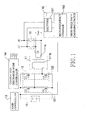
- an example of a line interactive UPS has a power switch set (10), a low-frequency transformer (11), a full-bridge switching circuit (12), a main controller (13), a charge and discharge mode controller (14), a rechargeable battery (15) and a high-frequency charging circuit (16).
- the power switch set (10) is connected with an AC power input terminal (AC IN).
- the AC power input terminal (AC IN) is connected to an AC power supply.
- the power switch set (10) determines if the AC power is supplied to a load (not shown).
- one terminal of the power switch set (10) is connected to the AC power input terminal (AC IN) and the other terminal (V out ) is connected to the load.
- the power switch set (10) is serially connected between the AC power input terminal (AC IN) and the load.
- the low-frequency transformer (11) has two windings (111a, 111b). One winding (111a) is connected to the load and is connected to the AC power supply through the power switch set (10).
- the full-bridge switching circuit (12) has two half-bridge switching circuits (121, 122). Serially connected nodes of the two half-bridge switching circuits (121, 122) are connected to the other winding (111b) of the low-frequency transformer (11).
- the main controller (13) is connected to the power switch set (10).
- the charge and discharge mode controller (14) is connected to the main controller (13) and the full-bridge switching circuit (12), and activates the full-bridge switching circuit (12) to enter a charging or discharging mode in accordance with a charge command or a discharge command from the main controller (12).
- the rechargeable battery (15) is connected to the full-bridge switching circuit (12) to perform charging or discharging through the full-bridge switching circuit (12).
- the high-frequency charging circuit (16) is connected between the AC power input terminal (AC IN) and the rechargeable battery (15) to convert the AC power into a DC current and charge the rechargeable battery (15).
- the high-frequency circuit (16) has a rectifier (161) and a high-frequency charger (162).
- the aforementioned line interactive UPS mainly adds a high-frequency charging circuit (16) between the AC power input terminal (AC IN) and the rechargeable battery (15).
- the high-frequency charging circuit (16) is activated if the power capacity of the rechargeable battery is not full and is detected.
- the DC power outputted by the rectifier (161) is converted to a DC power with a specific voltage, which is supplied to the rechargeable battery (15) to charge the rechargeable battery (15) and maintain full power capacity of the rechargeable battery (15).
- the line interactive UPS charges the rechargeable battery (15) without going through the low-frequency transformer (11) and the full-bridge switching circuit (12), and thus effectively avoids additional power loss.
- an embodiment of a line interactive UPS in accordance with the present invention is almost the same structurally except that an additional switch (17) is added.
- the switch (17) is serially connected between a winding (111a) of the low-frequency transformer (11) and a power switch set (10), and the switch (17) is controlled by the charge and discharge mode controller (14) to switch on or off.
- the charge and discharge mode controller (14) switches off the switch (17) to disconnect the low-frequency transformer (11) with the AC power supply and the load.
- the switch (17) may be one of a relay, a MOSFET, a TRIAC and an IGBT.
- the main controller outputs a small current charging mode command to the charge and discharge mode controller.
- the charge and discharge mode controller keeps switching off the switch and disconnects the low-frequency transformer with the AC power supply and the load. Meanwhile, the high-frequency charging circuit is activated to directly convert the AC power into a DC current to charge the rechargeable battery.
- the power of the rechargeable battery (15) of the UPS is converted into an AC power to supply the AC power to the load in case of a short period of the AC power outage, and the rechargeable battery drops to a low power capacity.
- the main controller (13) then outputs a large current charging mode command to the charge and discharge mode controller (14).
- the charge and discharge mode controller (14) keeps switching on the switch (17) to connect the low-frequency transformer (11) with the AC power supply and the load.
- the AC power supply performs fast charging to the rechargeable battery (15) with a large-current DC power through the low-frequency transformer (11) and the full-bridge switching circuit (12) until the rechargeable battery (15) reaches full power capacity.
- the present invention adds the high-frequency charging circuit to avoid the power loss caused by adopting the low-frequency transformer with a lower conversion efficiency to charge the rechargeable battery. Furthermore, when normal AC power is detected, the low-frequency transformer is disconnected with the AC power supply to prevent extra power consumption. Given such circuit structure, the UPS of the present invention only consumes 0.5 W in case of normal AC power, thereby attaining power-saving effect.
Landscapes
- Business, Economics & Management (AREA)
- Emergency Management (AREA)
- Engineering & Computer Science (AREA)
- Power Engineering (AREA)
- Charge And Discharge Circuits For Batteries Or The Like (AREA)
- Stand-By Power Supply Arrangements (AREA)
- Secondary Cells (AREA)
- Inverter Devices (AREA)
Claims (10)
- Stromsparende netzinteraktive unterbrechungsfreie Stromversorgung, umfassend:einen Stromschaltersatz (10), verbunden mit einem Wechselstromeingangsanschluss angepasst, um mit einer Wechselstromversorgung verbunden zu sein, um zu bestimmen, ob die Wechselstromversorgung Strom an eine Last liefert;einen Niederfrequenztransformator (11) mit zwei Windungen (111a, 111b), wobei eine Windung (111a) angepasst ist, um mit der Last verbunden zu sein und angepasst ist, um mit der Wechselstromversorgung verbunden zu sein;ein Full-Bridge-Schaltungskreis (12) mit zwei Half-Bridge-Schaltungskreisen (121, 122) mit seriell verbundenen Knotenpunkten, die mit der anderen Windung (111b) des Niederfrequenztransformator (11) verbunden sind;eine Hauptsteuerung (13), der mit dem Stromschaltersatz (10) verbunden ist;eine Lade- und Entlademodus-Steuerung (14), die mit der Hauptsteuerung (13) und dem Full-Bridge-Schaltungskreis (12) verbunden ist und den Full-Bridge-Schaltungskreis (12) aktiviert, so dass dieser in einen Lademodus oder Entlademodus eintritt, gemäß einem Ladebefehl oder Entladebefehl der Hauptsteuerung (13); undeine wiederaufladbare Batterie (15), die mit dem Full-Bridge-Schaltungskreis (12) verbunden ist und ein Laden oder Entladen durch den Full-Bridge-Schaltungskreis (12) durchführt;dadurch gekennzeichnet, dass die netzinteraktive unterbrechungsfreie Stromversorgung weiterhin umfasst:einen Schalter (17), der seriell zwischen den zwei Windungen (111a) des Niederfrequenztransformators (11) verbunden ist und mit der Wechselstromversorgung und dem Stromschaltersatz (10) verbunden ist und durch die Lade- und Entlademodus-Steuerung (14) gesteuert wird sich an- oder auszuschalten; undein Hochfrequenzladekreis (16), der zwischen dem Wechselstromeingangsanschluss und der wiederaufladbaren Batterie (15) verbunden ist, den Wechselstrom in einen Gleichstrom umwandelt, um die wiederaufladbaren Batterie (15) zu laden, und eine volle Stromkapazität der wiederaufladbaren Batterie (15) aufrechterhält während die Lade- und Entlademodus-Steuerung (14) den Schalter (17) weiter abschaltet und den Niederfrequenztransformators (11) von dem Stromschaltersatz (10) trennt, um so die wiederaufladbare Batterie (15) nur durch den Hochfrequenzladekreis (16) direkt zu laden ohne durch den Niederfrequenztransformator (11) und den Full-Bridge-Schaltungskreis (12) zu gehen, wenn erfasst wird, dass die wiederaufladbare Batterie (15) ein einem Erhaltungsladungszustand ist.
- Stromsparende netzinteraktive unterbrechungsfreie Stromversorgung gemäß Anspruch 1, wobei der Hochfrequenzladekreis (16) einen Stromrichter (161) und einen Hochfrequenzlader (162) umfasst.
- Stromsparende netzinteraktive unterbrechungsfreie Stromversorgung gemäß Anspruch 1, wobei der Schalter (17) ein Relay ist.
- Stromsparende netzinteraktive unterbrechungsfreie Stromversorgung gemäß Anspruch 2, wobei der Schalter (17) ein Relais ist.
- Stromsparende netzinteraktive unterbrechungsfreie Stromversorgung gemäß Anspruch 1, wobei der Schalter (17) ein Metall-Oxid-Halbleiter-Feldeffekttransistor ist.
- Stromsparende netzinteraktive unterbrechungsfreie Stromversorgung gemäß Anspruch 2, wobei der Schalter (17) ein Metall-Oxid-Halbleiter-Feldeffekttransistor ist.
- Stromsparende netzinteraktive unterbrechungsfreie Stromversorgung gemäß Anspruch 1, wobei der Schalter (17) ein TRIAC ist.
- Stromsparende netzinteraktive unterbrechungsfreie Stromversorgung gemäß Anspruch 2, wobei der Schalter (17) ein TRIAC ist.
- Stromsparende netzinteraktive unterbrechungsfreie Stromversorgung gemäß Anspruch 1, wobei der Schalter (17) ein Bipolartransistor mit isolierter Gate-Elektrode ist.
- Stromsparende netzinteraktive unterbrechungsfreie Stromversorgung gemäß Anspruch 2, wobei der Schalter (17) ein Bipolartransistor mit isolierter Gate-Elektrode ist.
Priority Applications (1)
| Application Number | Priority Date | Filing Date | Title |
|---|---|---|---|
| PL10162823T PL2290785T3 (pl) | 2009-08-28 | 2010-05-14 | Energooszczędny układ zasilania bezprzerwowego typu line interactive |
Applications Claiming Priority (1)
| Application Number | Priority Date | Filing Date | Title |
|---|---|---|---|
| TW98215886U TWM373601U (en) | 2009-08-28 | 2009-08-28 | Energy-saving on-line interactive type uninterruptible power supply system |
Publications (3)
| Publication Number | Publication Date |
|---|---|
| EP2290785A2 EP2290785A2 (de) | 2011-03-02 |
| EP2290785A3 EP2290785A3 (de) | 2013-03-06 |
| EP2290785B1 true EP2290785B1 (de) | 2014-04-23 |
Family
ID=42434328
Family Applications (1)
| Application Number | Title | Priority Date | Filing Date |
|---|---|---|---|
| EP20100162823 Active EP2290785B1 (de) | 2009-08-28 | 2010-05-14 | Stromsparende unterbrechungsfreie Netzinteraktive Stromversorgung |
Country Status (5)
| Country | Link |
|---|---|
| US (1) | US8314593B2 (de) |
| EP (1) | EP2290785B1 (de) |
| JP (1) | JP5486400B2 (de) |
| PL (1) | PL2290785T3 (de) |
| TW (1) | TWM373601U (de) |
Families Citing this family (13)
| Publication number | Priority date | Publication date | Assignee | Title |
|---|---|---|---|---|
| TWI387182B (zh) * | 2010-03-24 | 2013-02-21 | Powercom Co Ltd | 一種人體體溫感測式不斷電供電系統及其控制方法 |
| US20130187468A1 (en) | 2012-01-24 | 2013-07-25 | Google Inc. | Uninterruptible power supply control in distributed power architecture |
| WO2014052641A1 (en) * | 2012-09-28 | 2014-04-03 | Henry Shum | High-efficiency battery charger |
| CN103151809B (zh) * | 2012-11-15 | 2016-03-02 | 苏州华德睿电子科技有限公司 | 一种电源管理系统的高效变压控制的方法 |
| US20140265945A1 (en) * | 2013-03-15 | 2014-09-18 | Infineon Technologies Austria Ag | Electric Drive System |
| US20160079807A1 (en) * | 2013-06-25 | 2016-03-17 | Hewlett-Packard Development Company, L.P. | Uninterruptible power supply with inverter, charger, and active filter |
| US9979218B2 (en) * | 2013-11-22 | 2018-05-22 | Schneider Electric It Corporation | LPS architecture for UPS systems |
| US9379575B2 (en) * | 2014-03-07 | 2016-06-28 | Nissan North America, Inc. | Battery charger noise reduction by frequency switching |
| US10050548B2 (en) * | 2014-09-29 | 2018-08-14 | The Boeing Company | No-break power transfer |
| CN107546836B (zh) * | 2016-06-23 | 2019-11-26 | 维谛技术有限公司 | 一种ups电源 |
| JP6842545B2 (ja) * | 2016-12-15 | 2021-03-17 | ユー・ワン | 低放射無停電電源 |
| CN109428388A (zh) | 2017-09-01 | 2019-03-05 | 硕天科技股份有限公司 | 不断电电源系统 |
| US11011926B2 (en) * | 2018-07-03 | 2021-05-18 | Schneider Electric It Corporation | Adaptive charger |
Family Cites Families (13)
| Publication number | Priority date | Publication date | Assignee | Title |
|---|---|---|---|---|
| US5302858A (en) * | 1991-12-11 | 1994-04-12 | Best Power Technology, Incorporated | Method and apparatus for providing battery charging in a backup power system |
| US5567996A (en) * | 1995-01-30 | 1996-10-22 | Yu; Shih-Chung | AC power supply unit |
| US5602462A (en) * | 1995-02-21 | 1997-02-11 | Best Power Technology, Incorporated | Uninterruptible power system |
| JPH1014131A (ja) * | 1996-06-21 | 1998-01-16 | Hitachi Ltd | 直流出力付無停電電源装置 |
| JP3805844B2 (ja) * | 1996-12-05 | 2006-08-09 | 株式会社アイ・ヒッツ研究所 | 無停電電力供給装置 |
| JPH10228337A (ja) * | 1997-02-17 | 1998-08-25 | Nippon Electric Ind Co Ltd | 無停電機能付きコンピュータケース |
| US6178514B1 (en) * | 1998-07-31 | 2001-01-23 | Bradley C. Wood | Method and apparatus for connecting a device to a bus carrying power and a signal |
| AU4022900A (en) * | 1999-03-22 | 2000-10-09 | Escript, Inc. | Method and apparatus for medical covering group request processing, review and management |
| JP2002064947A (ja) * | 2000-08-18 | 2002-02-28 | Japan Storage Battery Co Ltd | 無停電直流電源装置 |
| JP2002118983A (ja) * | 2000-10-02 | 2002-04-19 | Toshiba Battery Co Ltd | 無停電電源装置 |
| US6479970B2 (en) * | 2001-04-03 | 2002-11-12 | Anantha B. Reddy | Un-interruptible power supply |
| JP4276193B2 (ja) * | 2005-03-03 | 2009-06-10 | 株式会社明電舎 | 瞬時電圧低下補償装置の充電方法 |
| JP2008161004A (ja) * | 2006-12-26 | 2008-07-10 | Fuji Electric Systems Co Ltd | 無停電電源装置 |
-
2009
- 2009-08-28 TW TW98215886U patent/TWM373601U/zh not_active IP Right Cessation
- 2009-10-22 US US12/603,952 patent/US8314593B2/en active Active
-
2010
- 2010-05-14 PL PL10162823T patent/PL2290785T3/pl unknown
- 2010-05-14 EP EP20100162823 patent/EP2290785B1/de active Active
- 2010-05-18 JP JP2010114259A patent/JP5486400B2/ja active Active
Also Published As
| Publication number | Publication date |
|---|---|
| JP2011050231A (ja) | 2011-03-10 |
| EP2290785A3 (de) | 2013-03-06 |
| PL2290785T3 (pl) | 2014-09-30 |
| US20110095727A1 (en) | 2011-04-28 |
| TWM373601U (en) | 2010-02-01 |
| JP5486400B2 (ja) | 2014-05-07 |
| US8314593B2 (en) | 2012-11-20 |
| EP2290785A2 (de) | 2011-03-02 |
Similar Documents
| Publication | Publication Date | Title |
|---|---|---|
| EP2290785B1 (de) | Stromsparende unterbrechungsfreie Netzinteraktive Stromversorgung | |
| US10637283B2 (en) | Power supply system and method | |
| US10014719B2 (en) | Uninterruptible power system | |
| JP5567684B2 (ja) | バッテリバランシング回路並びに第1の端子及び第2の端子を有するバッテリの複数のセルに蓄積されたエネルギーのバランシングを行う方法 | |
| CN202424295U (zh) | 一种逆变电源及应用所述逆变电源的供电系统 | |
| JP2011024299A (ja) | 電源回路 | |
| CN105634108B (zh) | 离线式不间断电源 | |
| JP2001103679A (ja) | 非常用電源装置 | |
| JP4487210B2 (ja) | 無停電電源装置 | |
| JP2003299247A (ja) | 交流電源供給システム | |
| CN102214918A (zh) | 高可靠性供电系统、方法及变频器系统 | |
| JPH04304160A (ja) | バッテリーバックアップ機能付き直流電源装置 | |
| EP3591801B1 (de) | Adaptives ladegerät | |
| US10491037B2 (en) | Uninterruptable power supply system | |
| US9450453B2 (en) | Uninterruptible power supply system with energy feedback to chargers and sinusoidal output | |
| US8760005B2 (en) | Control method of an uninterruptible power supply for extending a discharge time under a no-load condition | |
| WO2016031098A1 (ja) | 電源装置 | |
| CN100502216C (zh) | 非隔离式交流电源装置及其控制方法 | |
| KR20020015465A (ko) | 무정전 스위칭 모드 전원 장치 | |
| JP2015019540A (ja) | 電力供給システム | |
| CN111775979B (zh) | 一种连续循环充放电机车电源 | |
| CN210053247U (zh) | 一种采用双向dc/ac的电梯应急供电系统 | |
| CN210167851U (zh) | 一种变电站不停电电源电路 | |
| JP2000139040A (ja) | 無停電電源装置 | |
| CN120454272A (zh) | 一种双向充放电电路、方法、系统及系统控制方法 |
Legal Events
| Date | Code | Title | Description |
|---|---|---|---|
| PUAI | Public reference made under article 153(3) epc to a published international application that has entered the european phase |
Free format text: ORIGINAL CODE: 0009012 |
|
| AK | Designated contracting states |
Kind code of ref document: A2 Designated state(s): AL AT BE BG CH CY CZ DE DK EE ES FI FR GB GR HR HU IE IS IT LI LT LU LV MC MK MT NL NO PL PT RO SE SI SK SM TR |
|
| AX | Request for extension of the european patent |
Extension state: BA ME RS |
|
| PUAL | Search report despatched |
Free format text: ORIGINAL CODE: 0009013 |
|
| AK | Designated contracting states |
Kind code of ref document: A3 Designated state(s): AL AT BE BG CH CY CZ DE DK EE ES FI FR GB GR HR HU IE IS IT LI LT LU LV MC MK MT NL NO PL PT RO SE SI SK SM TR |
|
| AX | Request for extension of the european patent |
Extension state: BA ME RS |
|
| RIC1 | Information provided on ipc code assigned before grant |
Ipc: H02J 9/06 20060101AFI20130125BHEP |
|
| 17P | Request for examination filed |
Effective date: 20130805 |
|
| RBV | Designated contracting states (corrected) |
Designated state(s): AL AT BE BG CH CY CZ DE DK EE ES FI FR GB GR HR HU IE IS IT LI LT LU LV MC MK MT NL NO PL PT RO SE SI SK SM TR |
|
| REG | Reference to a national code |
Ref country code: DE Ref legal event code: R079 Ref document number: 602010015312 Country of ref document: DE Free format text: PREVIOUS MAIN CLASS: H02J0009000000 Ipc: H02J0009060000 |
|
| GRAP | Despatch of communication of intention to grant a patent |
Free format text: ORIGINAL CODE: EPIDOSNIGR1 |
|
| RIC1 | Information provided on ipc code assigned before grant |
Ipc: H02J 9/06 20060101AFI20131018BHEP |
|
| INTG | Intention to grant announced |
Effective date: 20131113 |
|
| GRAS | Grant fee paid |
Free format text: ORIGINAL CODE: EPIDOSNIGR3 |
|
| GRAA | (expected) grant |
Free format text: ORIGINAL CODE: 0009210 |
|
| AK | Designated contracting states |
Kind code of ref document: B1 Designated state(s): AL AT BE BG CH CY CZ DE DK EE ES FI FR GB GR HR HU IE IS IT LI LT LU LV MC MK MT NL NO PL PT RO SE SI SK SM TR |
|
| REG | Reference to a national code |
Ref country code: GB Ref legal event code: FG4D |
|
| REG | Reference to a national code |
Ref country code: CH Ref legal event code: EP |
|
| REG | Reference to a national code |
Ref country code: AT Ref legal event code: REF Ref document number: 664335 Country of ref document: AT Kind code of ref document: T Effective date: 20140515 |
|
| REG | Reference to a national code |
Ref country code: IE Ref legal event code: FG4D |
|
| REG | Reference to a national code |
Ref country code: DE Ref legal event code: R096 Ref document number: 602010015312 Country of ref document: DE Effective date: 20140605 |
|
| REG | Reference to a national code |
Ref country code: AT Ref legal event code: MK05 Ref document number: 664335 Country of ref document: AT Kind code of ref document: T Effective date: 20140423 |
|
| REG | Reference to a national code |
Ref country code: NL Ref legal event code: VDEP Effective date: 20140423 |
|
| REG | Reference to a national code |
Ref country code: LT Ref legal event code: MG4D |
|
| REG | Reference to a national code |
Ref country code: PL Ref legal event code: T3 |
|
| PG25 | Lapsed in a contracting state [announced via postgrant information from national office to epo] |
Ref country code: NO Free format text: LAPSE BECAUSE OF FAILURE TO SUBMIT A TRANSLATION OF THE DESCRIPTION OR TO PAY THE FEE WITHIN THE PRESCRIBED TIME-LIMIT Effective date: 20140723 Ref country code: FI Free format text: LAPSE BECAUSE OF FAILURE TO SUBMIT A TRANSLATION OF THE DESCRIPTION OR TO PAY THE FEE WITHIN THE PRESCRIBED TIME-LIMIT Effective date: 20140423 Ref country code: CY Free format text: LAPSE BECAUSE OF FAILURE TO SUBMIT A TRANSLATION OF THE DESCRIPTION OR TO PAY THE FEE WITHIN THE PRESCRIBED TIME-LIMIT Effective date: 20140423 Ref country code: LT Free format text: LAPSE BECAUSE OF FAILURE TO SUBMIT A TRANSLATION OF THE DESCRIPTION OR TO PAY THE FEE WITHIN THE PRESCRIBED TIME-LIMIT Effective date: 20140423 Ref country code: BG Free format text: LAPSE BECAUSE OF FAILURE TO SUBMIT A TRANSLATION OF THE DESCRIPTION OR TO PAY THE FEE WITHIN THE PRESCRIBED TIME-LIMIT Effective date: 20140723 Ref country code: GR Free format text: LAPSE BECAUSE OF FAILURE TO SUBMIT A TRANSLATION OF THE DESCRIPTION OR TO PAY THE FEE WITHIN THE PRESCRIBED TIME-LIMIT Effective date: 20140724 Ref country code: NL Free format text: LAPSE BECAUSE OF FAILURE TO SUBMIT A TRANSLATION OF THE DESCRIPTION OR TO PAY THE FEE WITHIN THE PRESCRIBED TIME-LIMIT Effective date: 20140423 Ref country code: IS Free format text: LAPSE BECAUSE OF FAILURE TO SUBMIT A TRANSLATION OF THE DESCRIPTION OR TO PAY THE FEE WITHIN THE PRESCRIBED TIME-LIMIT Effective date: 20140823 |
|
| PG25 | Lapsed in a contracting state [announced via postgrant information from national office to epo] |
Ref country code: SE Free format text: LAPSE BECAUSE OF FAILURE TO SUBMIT A TRANSLATION OF THE DESCRIPTION OR TO PAY THE FEE WITHIN THE PRESCRIBED TIME-LIMIT Effective date: 20140423 Ref country code: LV Free format text: LAPSE BECAUSE OF FAILURE TO SUBMIT A TRANSLATION OF THE DESCRIPTION OR TO PAY THE FEE WITHIN THE PRESCRIBED TIME-LIMIT Effective date: 20140423 Ref country code: AT Free format text: LAPSE BECAUSE OF FAILURE TO SUBMIT A TRANSLATION OF THE DESCRIPTION OR TO PAY THE FEE WITHIN THE PRESCRIBED TIME-LIMIT Effective date: 20140423 Ref country code: ES Free format text: LAPSE BECAUSE OF FAILURE TO SUBMIT A TRANSLATION OF THE DESCRIPTION OR TO PAY THE FEE WITHIN THE PRESCRIBED TIME-LIMIT Effective date: 20140423 Ref country code: HR Free format text: LAPSE BECAUSE OF FAILURE TO SUBMIT A TRANSLATION OF THE DESCRIPTION OR TO PAY THE FEE WITHIN THE PRESCRIBED TIME-LIMIT Effective date: 20140423 |
|
| PG25 | Lapsed in a contracting state [announced via postgrant information from national office to epo] |
Ref country code: PT Free format text: LAPSE BECAUSE OF FAILURE TO SUBMIT A TRANSLATION OF THE DESCRIPTION OR TO PAY THE FEE WITHIN THE PRESCRIBED TIME-LIMIT Effective date: 20140825 |
|
| REG | Reference to a national code |
Ref country code: CH Ref legal event code: PL |
|
| REG | Reference to a national code |
Ref country code: DE Ref legal event code: R097 Ref document number: 602010015312 Country of ref document: DE |
|
| PG25 | Lapsed in a contracting state [announced via postgrant information from national office to epo] |
Ref country code: MC Free format text: LAPSE BECAUSE OF FAILURE TO SUBMIT A TRANSLATION OF THE DESCRIPTION OR TO PAY THE FEE WITHIN THE PRESCRIBED TIME-LIMIT Effective date: 20140423 Ref country code: RO Free format text: LAPSE BECAUSE OF FAILURE TO SUBMIT A TRANSLATION OF THE DESCRIPTION OR TO PAY THE FEE WITHIN THE PRESCRIBED TIME-LIMIT Effective date: 20140423 Ref country code: EE Free format text: LAPSE BECAUSE OF FAILURE TO SUBMIT A TRANSLATION OF THE DESCRIPTION OR TO PAY THE FEE WITHIN THE PRESCRIBED TIME-LIMIT Effective date: 20140423 Ref country code: CZ Free format text: LAPSE BECAUSE OF FAILURE TO SUBMIT A TRANSLATION OF THE DESCRIPTION OR TO PAY THE FEE WITHIN THE PRESCRIBED TIME-LIMIT Effective date: 20140423 Ref country code: BE Free format text: LAPSE BECAUSE OF FAILURE TO SUBMIT A TRANSLATION OF THE DESCRIPTION OR TO PAY THE FEE WITHIN THE PRESCRIBED TIME-LIMIT Effective date: 20140423 Ref country code: SK Free format text: LAPSE BECAUSE OF FAILURE TO SUBMIT A TRANSLATION OF THE DESCRIPTION OR TO PAY THE FEE WITHIN THE PRESCRIBED TIME-LIMIT Effective date: 20140423 Ref country code: LI Free format text: LAPSE BECAUSE OF NON-PAYMENT OF DUE FEES Effective date: 20140531 Ref country code: CH Free format text: LAPSE BECAUSE OF NON-PAYMENT OF DUE FEES Effective date: 20140531 Ref country code: DK Free format text: LAPSE BECAUSE OF FAILURE TO SUBMIT A TRANSLATION OF THE DESCRIPTION OR TO PAY THE FEE WITHIN THE PRESCRIBED TIME-LIMIT Effective date: 20140423 |
|
| REG | Reference to a national code |
Ref country code: IE Ref legal event code: MM4A |
|
| PLBE | No opposition filed within time limit |
Free format text: ORIGINAL CODE: 0009261 |
|
| STAA | Information on the status of an ep patent application or granted ep patent |
Free format text: STATUS: NO OPPOSITION FILED WITHIN TIME LIMIT |
|
| 26N | No opposition filed |
Effective date: 20150126 |
|
| PG25 | Lapsed in a contracting state [announced via postgrant information from national office to epo] |
Ref country code: IE Free format text: LAPSE BECAUSE OF NON-PAYMENT OF DUE FEES Effective date: 20140514 |
|
| REG | Reference to a national code |
Ref country code: DE Ref legal event code: R097 Ref document number: 602010015312 Country of ref document: DE Effective date: 20150126 |
|
| PG25 | Lapsed in a contracting state [announced via postgrant information from national office to epo] |
Ref country code: SI Free format text: LAPSE BECAUSE OF FAILURE TO SUBMIT A TRANSLATION OF THE DESCRIPTION OR TO PAY THE FEE WITHIN THE PRESCRIBED TIME-LIMIT Effective date: 20140423 |
|
| PG25 | Lapsed in a contracting state [announced via postgrant information from national office to epo] |
Ref country code: MT Free format text: LAPSE BECAUSE OF FAILURE TO SUBMIT A TRANSLATION OF THE DESCRIPTION OR TO PAY THE FEE WITHIN THE PRESCRIBED TIME-LIMIT Effective date: 20140423 |
|
| PG25 | Lapsed in a contracting state [announced via postgrant information from national office to epo] |
Ref country code: SM Free format text: LAPSE BECAUSE OF FAILURE TO SUBMIT A TRANSLATION OF THE DESCRIPTION OR TO PAY THE FEE WITHIN THE PRESCRIBED TIME-LIMIT Effective date: 20140423 |
|
| REG | Reference to a national code |
Ref country code: FR Ref legal event code: PLFP Year of fee payment: 7 |
|
| PG25 | Lapsed in a contracting state [announced via postgrant information from national office to epo] |
Ref country code: TR Free format text: LAPSE BECAUSE OF FAILURE TO SUBMIT A TRANSLATION OF THE DESCRIPTION OR TO PAY THE FEE WITHIN THE PRESCRIBED TIME-LIMIT Effective date: 20140423 Ref country code: HU Free format text: LAPSE BECAUSE OF FAILURE TO SUBMIT A TRANSLATION OF THE DESCRIPTION OR TO PAY THE FEE WITHIN THE PRESCRIBED TIME-LIMIT; INVALID AB INITIO Effective date: 20100514 Ref country code: LU Free format text: LAPSE BECAUSE OF NON-PAYMENT OF DUE FEES Effective date: 20140514 |
|
| REG | Reference to a national code |
Ref country code: FR Ref legal event code: PLFP Year of fee payment: 8 |
|
| REG | Reference to a national code |
Ref country code: FR Ref legal event code: PLFP Year of fee payment: 9 |
|
| PG25 | Lapsed in a contracting state [announced via postgrant information from national office to epo] |
Ref country code: MK Free format text: LAPSE BECAUSE OF FAILURE TO SUBMIT A TRANSLATION OF THE DESCRIPTION OR TO PAY THE FEE WITHIN THE PRESCRIBED TIME-LIMIT Effective date: 20140423 |
|
| PG25 | Lapsed in a contracting state [announced via postgrant information from national office to epo] |
Ref country code: AL Free format text: LAPSE BECAUSE OF FAILURE TO SUBMIT A TRANSLATION OF THE DESCRIPTION OR TO PAY THE FEE WITHIN THE PRESCRIBED TIME-LIMIT Effective date: 20140423 |
|
| PGFP | Annual fee paid to national office [announced via postgrant information from national office to epo] |
Ref country code: FR Payment date: 20250318 Year of fee payment: 16 |
|
| PGFP | Annual fee paid to national office [announced via postgrant information from national office to epo] |
Ref country code: GB Payment date: 20250314 Year of fee payment: 16 |
|
| PGFP | Annual fee paid to national office [announced via postgrant information from national office to epo] |
Ref country code: DE Payment date: 20250409 Year of fee payment: 16 Ref country code: PL Payment date: 20250513 Year of fee payment: 16 |
|
| PGFP | Annual fee paid to national office [announced via postgrant information from national office to epo] |
Ref country code: IT Payment date: 20250530 Year of fee payment: 16 |