EP2290733A1 - Batteriesystem und dieses enthaltendes Elektrofahrzeug - Google Patents
Batteriesystem und dieses enthaltendes Elektrofahrzeug Download PDFInfo
- Publication number
- EP2290733A1 EP2290733A1 EP10251325A EP10251325A EP2290733A1 EP 2290733 A1 EP2290733 A1 EP 2290733A1 EP 10251325 A EP10251325 A EP 10251325A EP 10251325 A EP10251325 A EP 10251325A EP 2290733 A1 EP2290733 A1 EP 2290733A1
- Authority
- EP
- European Patent Office
- Prior art keywords
- battery
- module
- battery module
- modules
- battery modules
- Prior art date
- Legal status (The legal status is an assumption and is not a legal conclusion. Google has not performed a legal analysis and makes no representation as to the accuracy of the status listed.)
- Withdrawn
Links
Images


Classifications
-
- H—ELECTRICITY
- H01—ELECTRIC ELEMENTS
- H01M—PROCESSES OR MEANS, e.g. BATTERIES, FOR THE DIRECT CONVERSION OF CHEMICAL ENERGY INTO ELECTRICAL ENERGY
- H01M10/00—Secondary cells; Manufacture thereof
- H01M10/42—Methods or arrangements for servicing or maintenance of secondary cells or secondary half-cells
- H01M10/425—Structural combination with electronic components, e.g. electronic circuits integrated to the outside of the casing
-
- G—PHYSICS
- G01—MEASURING; TESTING
- G01R—MEASURING ELECTRIC VARIABLES; MEASURING MAGNETIC VARIABLES
- G01R31/00—Arrangements for testing electric properties; Arrangements for locating electric faults; Arrangements for electrical testing characterised by what is being tested not provided for elsewhere
- G01R31/36—Arrangements for testing, measuring or monitoring the electrical condition of accumulators or electric batteries, e.g. capacity or state of charge [SoC]
- G01R31/382—Arrangements for monitoring battery or accumulator variables, e.g. SoC
- G01R31/3835—Arrangements for monitoring battery or accumulator variables, e.g. SoC involving only voltage measurements
-
- B—PERFORMING OPERATIONS; TRANSPORTING
- B60—VEHICLES IN GENERAL
- B60L—PROPULSION OF ELECTRICALLY-PROPELLED VEHICLES; SUPPLYING ELECTRIC POWER FOR AUXILIARY EQUIPMENT OF ELECTRICALLY-PROPELLED VEHICLES; ELECTRODYNAMIC BRAKE SYSTEMS FOR VEHICLES IN GENERAL; MAGNETIC SUSPENSION OR LEVITATION FOR VEHICLES; MONITORING OPERATING VARIABLES OF ELECTRICALLY-PROPELLED VEHICLES; ELECTRIC SAFETY DEVICES FOR ELECTRICALLY-PROPELLED VEHICLES
- B60L58/00—Methods or circuit arrangements for monitoring or controlling batteries or fuel cells, specially adapted for electric vehicles
- B60L58/10—Methods or circuit arrangements for monitoring or controlling batteries or fuel cells, specially adapted for electric vehicles for monitoring or controlling batteries
- B60L58/18—Methods or circuit arrangements for monitoring or controlling batteries or fuel cells, specially adapted for electric vehicles for monitoring or controlling batteries of two or more battery modules
-
- G—PHYSICS
- G01—MEASURING; TESTING
- G01R—MEASURING ELECTRIC VARIABLES; MEASURING MAGNETIC VARIABLES
- G01R31/00—Arrangements for testing electric properties; Arrangements for locating electric faults; Arrangements for electrical testing characterised by what is being tested not provided for elsewhere
- G01R31/36—Arrangements for testing, measuring or monitoring the electrical condition of accumulators or electric batteries, e.g. capacity or state of charge [SoC]
- G01R31/396—Acquisition or processing of data for testing or for monitoring individual cells or groups of cells within a battery
-
- H—ELECTRICITY
- H01—ELECTRIC ELEMENTS
- H01M—PROCESSES OR MEANS, e.g. BATTERIES, FOR THE DIRECT CONVERSION OF CHEMICAL ENERGY INTO ELECTRICAL ENERGY
- H01M10/00—Secondary cells; Manufacture thereof
- H01M10/42—Methods or arrangements for servicing or maintenance of secondary cells or secondary half-cells
- H01M10/48—Accumulators combined with arrangements for measuring, testing or indicating the condition of cells, e.g. the level or density of the electrolyte
- H01M10/482—Accumulators combined with arrangements for measuring, testing or indicating the condition of cells, e.g. the level or density of the electrolyte for several batteries or cells simultaneously or sequentially
-
- H—ELECTRICITY
- H01—ELECTRIC ELEMENTS
- H01M—PROCESSES OR MEANS, e.g. BATTERIES, FOR THE DIRECT CONVERSION OF CHEMICAL ENERGY INTO ELECTRICAL ENERGY
- H01M10/00—Secondary cells; Manufacture thereof
- H01M10/42—Methods or arrangements for servicing or maintenance of secondary cells or secondary half-cells
- H01M10/48—Accumulators combined with arrangements for measuring, testing or indicating the condition of cells, e.g. the level or density of the electrolyte
- H01M10/486—Accumulators combined with arrangements for measuring, testing or indicating the condition of cells, e.g. the level or density of the electrolyte for measuring temperature
-
- H—ELECTRICITY
- H01—ELECTRIC ELEMENTS
- H01M—PROCESSES OR MEANS, e.g. BATTERIES, FOR THE DIRECT CONVERSION OF CHEMICAL ENERGY INTO ELECTRICAL ENERGY
- H01M50/00—Constructional details or processes of manufacture of the non-active parts of electrochemical cells other than fuel cells, e.g. hybrid cells
- H01M50/50—Current conducting connections for cells or batteries
- H01M50/569—Constructional details of current conducting connections for detecting conditions inside cells or batteries, e.g. details of voltage sensing terminals
-
- H—ELECTRICITY
- H01—ELECTRIC ELEMENTS
- H01M—PROCESSES OR MEANS, e.g. BATTERIES, FOR THE DIRECT CONVERSION OF CHEMICAL ENERGY INTO ELECTRICAL ENERGY
- H01M2200/00—Safety devices for primary or secondary batteries
- H01M2200/10—Temperature sensitive devices
- H01M2200/106—PTC
-
- H—ELECTRICITY
- H01—ELECTRIC ELEMENTS
- H01M—PROCESSES OR MEANS, e.g. BATTERIES, FOR THE DIRECT CONVERSION OF CHEMICAL ENERGY INTO ELECTRICAL ENERGY
- H01M50/00—Constructional details or processes of manufacture of the non-active parts of electrochemical cells other than fuel cells, e.g. hybrid cells
- H01M50/50—Current conducting connections for cells or batteries
- H01M50/502—Interconnectors for connecting terminals of adjacent batteries; Interconnectors for connecting cells outside a battery casing
- H01M50/503—Interconnectors for connecting terminals of adjacent batteries; Interconnectors for connecting cells outside a battery casing characterised by the shape of the interconnectors
-
- H—ELECTRICITY
- H01—ELECTRIC ELEMENTS
- H01M—PROCESSES OR MEANS, e.g. BATTERIES, FOR THE DIRECT CONVERSION OF CHEMICAL ENERGY INTO ELECTRICAL ENERGY
- H01M50/00—Constructional details or processes of manufacture of the non-active parts of electrochemical cells other than fuel cells, e.g. hybrid cells
- H01M50/50—Current conducting connections for cells or batteries
- H01M50/502—Interconnectors for connecting terminals of adjacent batteries; Interconnectors for connecting cells outside a battery casing
- H01M50/505—Interconnectors for connecting terminals of adjacent batteries; Interconnectors for connecting cells outside a battery casing comprising a single busbar
-
- H—ELECTRICITY
- H01—ELECTRIC ELEMENTS
- H01M—PROCESSES OR MEANS, e.g. BATTERIES, FOR THE DIRECT CONVERSION OF CHEMICAL ENERGY INTO ELECTRICAL ENERGY
- H01M50/00—Constructional details or processes of manufacture of the non-active parts of electrochemical cells other than fuel cells, e.g. hybrid cells
- H01M50/50—Current conducting connections for cells or batteries
- H01M50/502—Interconnectors for connecting terminals of adjacent batteries; Interconnectors for connecting cells outside a battery casing
- H01M50/509—Interconnectors for connecting terminals of adjacent batteries; Interconnectors for connecting cells outside a battery casing characterised by the type of connection, e.g. mixed connections
- H01M50/51—Connection only in series
-
- H—ELECTRICITY
- H01—ELECTRIC ELEMENTS
- H01M—PROCESSES OR MEANS, e.g. BATTERIES, FOR THE DIRECT CONVERSION OF CHEMICAL ENERGY INTO ELECTRICAL ENERGY
- H01M50/00—Constructional details or processes of manufacture of the non-active parts of electrochemical cells other than fuel cells, e.g. hybrid cells
- H01M50/50—Current conducting connections for cells or batteries
- H01M50/502—Interconnectors for connecting terminals of adjacent batteries; Interconnectors for connecting cells outside a battery casing
- H01M50/521—Interconnectors for connecting terminals of adjacent batteries; Interconnectors for connecting cells outside a battery casing characterised by the material
- H01M50/522—Inorganic material
-
- H—ELECTRICITY
- H01—ELECTRIC ELEMENTS
- H01M—PROCESSES OR MEANS, e.g. BATTERIES, FOR THE DIRECT CONVERSION OF CHEMICAL ENERGY INTO ELECTRICAL ENERGY
- H01M50/00—Constructional details or processes of manufacture of the non-active parts of electrochemical cells other than fuel cells, e.g. hybrid cells
- H01M50/50—Current conducting connections for cells or batteries
- H01M50/502—Interconnectors for connecting terminals of adjacent batteries; Interconnectors for connecting cells outside a battery casing
- H01M50/521—Interconnectors for connecting terminals of adjacent batteries; Interconnectors for connecting cells outside a battery casing characterised by the material
- H01M50/526—Interconnectors for connecting terminals of adjacent batteries; Interconnectors for connecting cells outside a battery casing characterised by the material having a layered structure
-
- Y—GENERAL TAGGING OF NEW TECHNOLOGICAL DEVELOPMENTS; GENERAL TAGGING OF CROSS-SECTIONAL TECHNOLOGIES SPANNING OVER SEVERAL SECTIONS OF THE IPC; TECHNICAL SUBJECTS COVERED BY FORMER USPC CROSS-REFERENCE ART COLLECTIONS [XRACs] AND DIGESTS
- Y02—TECHNOLOGIES OR APPLICATIONS FOR MITIGATION OR ADAPTATION AGAINST CLIMATE CHANGE
- Y02E—REDUCTION OF GREENHOUSE GAS [GHG] EMISSIONS, RELATED TO ENERGY GENERATION, TRANSMISSION OR DISTRIBUTION
- Y02E60/00—Enabling technologies; Technologies with a potential or indirect contribution to GHG emissions mitigation
- Y02E60/10—Energy storage using batteries
Definitions
- the present invention relates to a battery system including a battery module, and an electric vehicle.
- Chargeable and dischargeable battery modules are used as driving sources of movable objects such as electric automobiles.
- a battery module includes a plurality of batteries (battery cells) connected in series, for example.
- JP 8-162171 A describes the monitoring device of a battery pack including the plurality of modules connected in series.
- the monitoring device is provided with a plurality of voltage measuring units that correspond to the plurality of battery modules, respectively.
- Each voltage measuring unit includes a voltage detecting circuit connected to a positive electrode terminal and a negative electrode terminal of the corresponding battery module. Thus, the voltage between the both terminals of the battery module is detected by the voltage detecting circuit.
- a great number of battery modules are provided in the battery system that is used as the driving source of the movable object in order to provide a given driving force.
- An object of the present invention is to provide a battery system in which complicated configuration and increased cost can be suppressed and capacity can be increased, and an electric vehicle including the same.
- the battery system according to the present embodiment is mounted on an electric vehicle (an electric automobile, for example) using electric power as a driving source.
- Fig. 1 is a block diagram showing the schematic configuration of the battery system according to the first embodiment.
- main constituents of the battery system 500 are a plurality of battery modules 100, a plurality of detecting circuits 20, a battery ECU (Electronic Control Unit) 101 and a contactor 102, and the battery system 500 is connected to a main controller 300 of the electric vehicle via a bus 104.
- the battery system 500 includes a casing that is not shown. The components of the battery system 500 are housed in the casing.
- the plurality of battery modules 100 of the battery system 500 are connected to one another through power supply lines 501.
- One detecting circuit 20 is provided in common for two battery modules 100.
- Each detecting circuit 20 is used in common for two battery modules 100. Details will be described below.
- a configuration mainly composed of the two battery modules 100, and the detecting circuit 20 that is used in common for the two battery modules 100 is referred to as a module group 100A.
- Fig. 2 is a block diagram showing the configuration of the module group 100A of Fig. 1 . As shown in Fig. 2 , the two battery modules 100 of the module group 100A are connected to each other through the power supply line 501. Each battery module 100 includes a plurality of (eighteen in this example) battery cells 10 and a plurality of (five in this example) thermistors 11.
- each battery module 100 the plurality of battery cells 10 are integrally arranged so as to be adjacent to one another, and are connected in series through a plurality of bus bars 40.
- Each battery cell 10 is a secondary battery such as a lithium-ion battery or a nickel metal hydride battery.
- the battery cells 10 arranged at both ends of the battery module 100 are connected to the power supply lines 501 through bus bars 40a, respectively. In this manner, all the battery cells 10 of the plurality of battery modules 100 are connected in series in the battery system 500.
- the power supply lines 501 pulled out from the battery system 500 are connected to a load such as a motor of the electric vehicle.
- the detecting circuit 20 is attached to one battery module 100 (see Fig. 3 , described below) of the two battery modules 100 in the module group 100A.
- the detecting circuit 20 is electrically connected to all the bus bars 40, 40a of the two battery modules 100 through conductor lines 52 and PTC (Positive Temperature Coefficient) elements 60.
- the detecting circuit 20 is electrically connected to all the thermistors 11 of the two battery modules 100.
- the detecting circuit 20 detects a voltage between terminals of each battery cell 10 by detecting potential differences between the bus bars 40, 40a connecting the plurality of battery cells 10.
- the detecting circuit 20 functions as a voltage detector. Details will be described below.
- the detecting circuit 20 detects a temperature at a given portion of each battery module 100 based on a signal output from the plurality of thermistors 11.
- the detecting circuit 20 functions as a temperature detector.
- At least one bus bar 40, 40a of the plurality of bus bars 40, 40a of each battery module 100 is used as a shunt resistance for current detection.
- the detecting circuit 20 detects a current flowing through each battery module 100 by detecting a voltage at both ends of the bus bar 40, 40a used as the shunt resistance.
- the detecting circuit 20 functions as a current detector.
- the PTC element 60 has such resistance temperature characteristics as to have a resistance value rapidly increasing when its temperature exceeds a certain value. Therefore, if a short occurs in the detecting circuit 20 and the conductor line 52, for example, the temperature of the PTC element 60 that rises because of the current flowing through the short-circuited path causes the resistance value of the PTC element 60 to increase. Accordingly, a large current is inhibited from flowing through the short-circuited path including the PTC element 60.
- the detecting circuit 20 of the module group 100A is connected to the battery ECU 101 through a bus 103. This causes the voltage, current and temperature detected by the detecting circuit 20 to be given to the battery ECU 101.
- the battery ECU 101 calculates the charged capacity of each battery cell 10 based on the voltage, current and temperature given from each detecting circuit 20, for example, and controls charge / discharge of each battery module based on the charged capacity. In addition, the battery ECU 101 detects abnormality of each battery module 100 based on the voltage, current and temperature given from each detecting circuit 20. The abnormality of the battery module 100 includes overdischarge, overcharge or abnormal temperature of the battery cells 10.
- the battery ECU 101 calculates the charged capacity of the battery cell 10 and detects the overdischarge, overcharge or temperature abnormality, for example, of the battery cell 10 in this embodiment, the present invention is not limited to this.
- the detecting circuit 20 may calculate the charged capacity of the battery cell 10 and detect the overdischarge, overcharge or temperature abnormality, for example, of the battery cell 10, and give the detection results to the battery ECU 101.
- the contactor 102 is inserted in the power supply line 501 connected to the battery module 100 at one end of the battery system 500.
- the battery ECU 101 turns off the contactor 102 when it detects the abnormality of the battery module 100. Since the current does not flow through each battery module 100 in the case of an occurrence of the abnormality, the battery module 100 is prevented from being abnormally heated.
- the battery ECU 101 is connected to the main controller 300 through the bus 104.
- the charged capacity of each battery module 100 (the charged capacity of each battery cell 10 of Fig. 2 ) is given from the battery ECU 101 to the main controller 300.
- the main controller 300 controls power of the electric vehicle (a rotational speed of the motor, for example) based on the charged capacity.
- the main controller 300 controls a power generating system, not shown, connected to the power supply line 501 to cause each battery module 100 to be charged.
- the motor connected to the power supply line 501 functions as the power generating system in this embodiment.
- the motor converts electric power supplied from the battery system 500 into power for driving the drive wheel, which is not shown, at the time of acceleration of the electric vehicle.
- the motor generates regenerated electric power at the time of deceleration of the electric vehicle.
- Each battery module 100 is charged with the regenerated electric power.
- the foregoing detecting circuit 20 is attached to the battery module 100 described below.
- Fig. 3 is an external perspective view of the battery module 100
- Fig. 4 is a plan view of the battery module 100
- Fig. 5 is an end view of the battery module 100.
- Figs. 3 to 5 and Figs. 7 , 8 , 10 to 19 , 21 and 23 to 27 described below three directions that are perpendicular to one another are defined as an X-direction, a Y-direction and a Z-direction as indicated by the arrows X, Y, Z.
- the X-direction and the Y-direction are parallel to a horizontal plane, and the Z-direction is perpendicular to the horizontal plane in this example.
- the plurality of battery cells 10 each having a flat and substantially rectangular parallelepiped shape are arranged to line up in the X direction in the battery module 100.
- the plurality of battery cells 10 are integrally fixed by a pair of end surface frames 92, a pair of upper end frames 93 and a pair of lower end frames 94.
- Each of the pair of end surface frames 92 has a substantially plate shape, and is arranged parallel to the Y-Z plane.
- the pair of upper end frames 93 and the pair of lower end frames 94 are arranged to extend in the X-direction.
- Connection portions for connecting the pair of upper end frames 93 and the pair of lower end frames 94 thereto are formed at four corners of each of the pair of end surface frames 92.
- the pair of upper end frames 93 is attached to the upper connection portions of the pair of end surface frames 92
- the pair of lower end frames 94 is attached to the lower connection portions of the pair of end surface frames 92 while the plurality of battery cells 10 are arranged between the pair of end surface frames 92. Accordingly, the plurality of battery cells 10 are integrally fixed while being arranged to line up in the X-direction.
- a rigid printed circuit board (hereinafter abbreviated as a printed circuit board) 21 is attached to an outer surface of one end surface frame 92 with a distance therebetween.
- the detecting circuit 20 is provided on the printed circuit board 21.
- the plurality of battery cells 10 each have a plus electrode 10a arranged on an upper surface portion on one end side or the other end side in the Y-direction, and have a minus electrode 10b arranged on an upper surface portion on the opposite side.
- Each of the electrodes 10a, 10b is provided to be inclined and project upward (see Fig. 5 ).
- the battery cell 10 adjacent to the end surface frame 92 to which the printed circuit board 21 is not attached to the battery cell 10 adjacent to the end surface frame 92 to which the printed circuit board 21 is attached are referred to as a first battery cell 10 to an eighteenth battery cell 10.
- the battery cells 10 are arranged such that the positional relationship between the plus electrode 10a and the minus electrode 10b of each battery cell 10 in the Y-direction is opposite to that of the adjacent battery cell 10, as shown in Fig. 4 .
- the plus electrode 10a of one battery cell 10 is in close proximity to the minus electrode 10b of the other battery cell 10
- the minus electrode 10b of the one battery cel1 10 is in close proximity to the plus electrode 10a of the other battery cell 10.
- the bus bar 40 is attached to the two electrodes being in close proximity to each other. This causes the plurality of battery cells 10 to be connected in series.
- the common bus bar 40 is attached to the plus electrode 10a of the first battery cell 10 and the minus electrode 10b of the second battery cell 10.
- the common bus bar 40 is attached to the plus electrode 10a of the second battery cell 10 and the minus electrode 10b of the third battery cell 10.
- the common bus bar 40 is attached to the plus electrode 10a of each of the odd numbered battery cells 10 and the minus electrode 10b of each of the even numbered battery cells 10 adjacent thereto.
- the common bus bar 40 is attached to the plus electrode 10a of each of the even numbered battery cells 10 and the minus electrode 10b of each of the odd numbered battery cells 10 adjacent thereto.
- the bus bar 40a for connecting the power supply line 501 from the exterior is attached to each of the minus electrode 10b of the first battery cell 10 and the plus electrode 10a of the eighteenth battery cell 10.
- a long-sized flexible printed circuit board (hereinafter abbreviated as an FPC board) 50 extending in the X-direction is connected in common to the plurality of bus bars 40 on the one end side of the plurality of battery cells 10 in the Y-direction.
- a long-sized FPC board 50 extending in the X-direction is connected in common to the plurality of bus bars 40, 40a on the other end side of the plurality of battery cells 10 in the Y-direction.
- the FPC board 50 having bending characteristics and flexibility mainly includes a plurality of conductor lines (wiring traces) 51, 52 (see Fig. 8 , described below) formed on an insulating layer.
- Examples of the material for the insulating layer constituting the FPC board 50 include polyimide, and examples of the material for the conductor lines 51, 52 (see Fig. 8 , described below) include copper.
- the PTC elements 60 are arranged close to the bus bars 40, 40a, respectively, on the FPC board 50.
- Each FPC board 50 is bent inward at a right angle and further bent downward at an upper end portion of the end surface frame 92 (the end surface frame 92 to which the printed circuit board 21 is attached) to be connected to the printed circuit board 21.
- Two FPC boards 50 of the battery module 100 to which the detecting circuit 20 is not attached are connected to the printed circuit board 21 attached to the other battery module 100 of the same module group 100A.
- bus bar 40 for connecting the plus electrode 10a and the minus electrode 10b of two adjacent battery cells 10 is referred to as the bus bar for two electrodes 40
- bus bar 40a for connecting the plus electrode 10a or the minus electrode 10b of one battery cell 10 and the power supply line 501 is referred to as the bus bar for one electrode 40a.
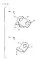
- Fig. 6 (a) is an external perspective view of the bus bar for two electrodes 40
- Fig. 6(b) is an external perspective view of the bus bar for one electrode 40a.
- the bus bar for two electrodes 40 includes a base portion 41 having a substantially rectangular shape and a pair of attachment portions 42 that is bent and extends toward one surface side from one side of the base portion 41.
- a pair of electrode connection holes 43 is formed in the base portion 41.
- the bus bar for one electrode 40a includes a base portion 45 having a substantially square shape and an attachment portion 46 that is bent and extends toward one surface side from one side of the base portion 45.
- An electrode connection hole 47 is formed in the base portion 45.
- the bus bars 40, 40a are each composed of tough pitch copper having a nickel-plated surface, for example.
- Fig. 7 is an external perspective view of the FPC boards 50 to which the plurality of bus bars 40, 40a and the plurality of PTC elements 60 are attached.
- the attachment portions 42, 46 of the plurality of bus bars 40, 40a are attached to the two FPC boards 50 at given spacings along the X-direction.
- the plurality of PTC elements 60 are attached to the two FPC boards 50 at the same spacings as the spacings between the plurality of bus bars 40, 40a.
- the two FPC boards 50 each having the plurality of bus bars 40, 40a and the plurality of PTC elements 60 attached thereto in the foregoing manner are attached to the plurality of battery cells 10 that are integrally fixed by the end surface frames 92 (see Fig. 3 ), the upper end frames 93 (see Fig. 3 ) and the lower end frames 94 (see Fig. 3 ) during the manufacture of the battery module 100.
- the plus electrode 10a and the minus electrode 10b of the adjacent battery cells 10 are fitted in the electrode connection holes 43, 47 formed in each bus bar 40, 40a.
- a male thread is formed at each of the plus electrodes 10a and the minus electrodes 10b.
- the male threads of the plus electrodes 10a and the minus electrodes 10b are screwed in nuts (not shown).
- the plurality of bus bars 40, 40a are attached to the plurality of battery cells 10 while the FPC boards 50 are held in a substantially horizontal attitude by the plurality of bus bars 40, 40a.
- Fig. 8 is a schematic plan view for explaining connection between the bus bars 40, 40a and the detecting circuit 20. In this example, description is made of connection between the bus bars 40, 40a and the detecting circuit 20 in the battery module 100 to which the detecting circuit 20 is attached.
- each FPC board 50 is provided with the plurality of conductor lines 51, 52 that correspond to the plurality of bus bars 40, 40a, respectively.
- Each conductor line 51 is provided to extend parallel to the Y-direction between the attachment portion 42, 46 in the bus bar 40, 40a and the PTC element 60 arranged in the vicinity of the bus bar 40.
- Each conductor line 52 is provided to extend parallel to the X-direction between the PTC element 60 and one end of the FPC board 50.
- each conductor line 51 is provided to be exposed on the lower surface of the FPC board 50.
- the one end of each conductor line 51 exposed on the lower surface is electrically connected to the attachment portion 42, 46 in the bus bar 40, 40a by soldering or welding, for example. Accordingly, the FPC board 50 is fixed to each of the bus bars 40, 40a.
- each conductor line 51 and one end of each conductor line 52 are provided to be exposed on the upper surface of the FPC board 50.
- a pair of terminals (not illustrated) of the PTC element 60 is connected to the other end of each conductor line 51 and one end of each conductor line 52 by soldering, for example.
- Each of the PTC elements 60 is preferably arranged in a region between both ends in the X-direction of the corresponding bus bar 40, 40a.
- a region of the FPC board 50 between the adjacent bus bars 40, 40a is easily deflected.
- the region of the FPC board 50 between both the ends of each of the bus bars 40, 40a is kept relatively flat because it is fixed to the bus bar 40, 40a. Therefore, each of the PTC elements 60 is arranged within the region of the FPC board 50 between both the ends of each of the bus bars 40, 40a so that connection characteristics between the PTC element 60 and the conductor lines 51, 52 are sufficiently ensured.
- the effect of deflection of the FPC board 50 on each of the PTC elements 60 e.g., a change in the resistance value of the PTC element 60
- a plurality of connection terminals 22 corresponding to the plurality of conductor lines 52, respectively, of the FPC boards 50 are provided in the printed circuit board 21.
- the other ends of the conductor lines 52 of the FPC boards 50 are connected to the corresponding connection terminals 22 by soldering or welding, for example.
- the printed circuit board 21 and the FPC boards 50 may not be connected by soldering or welding.
- connecters may be used for connecting the printed circuit board 21 and the FPC boards 50.
- each of the bus bars 40, 40a is electrically connected to the detecting circuit 20 via the PTC element 60.
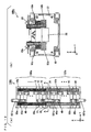
- Fig. 9 is a block diagram showing an example of the configuration of the detecting circuit 20.
- the detecting circuit 20 shown in Fig. 9 includes first and second voltage detecting ICs (Integrated Circuits) 20a, 20b.
- the first voltage detecting IC 20a is provided corresponding to one battery module 100 of the module group 100A (see Fig. 2 ), and the second voltage detecting IC 20b is provided corresponding to the other battery module 100 in this example.
- the first and second voltage detecting ICs 20a, 20b are mounted on one printed circuit board 21.
- the plurality of bus bars 40, 40a (see Fig. 2 ) of the one battery module 100 and the first voltage detecting IC 20a are connected through the plurality of conductor lines 52.
- the plurality of bus bars 40, 40a (see Fig. 2 ) of the other battery module 100 and the second voltage detecting IC 20b are connected through the plurality of conductor lines 52. Accordingly, the terminal voltage of each battery cell 10 (see Fig. 2 ) in the two battery modules 100 is detected.
- the plurality of conductor lines 52 connecting the plurality of bus bars 40, 40a of the one battery module 100 and the first voltage detecting IC 20a are indicated by one line.
- the plurality of conductor lines 52 connecting the plurality of bus bars 40, 40a of the other battery module 100 and the second voltage detecting IC 20b are indicated by one line.
- a plurality of (two or three, for example) voltage detecting ICs corresponding to one battery module 100 may be mounted on one printed circuit board 21 instead of the foregoing first and second voltage detecting ICs 20a, 20b.
- each voltage detecting IC detects the respective terminal voltages of the previously assigned battery cells 10.
- One voltage detecting IC corresponding to two battery modules 100 of the module group 100A may be mounted on one printed circuit board 21 instead of the foregoing first and second voltage detecting ICs 20a, 20b. In this case, the respective terminal voltages of all the battery cells 10 (see Fig. 2 ) in the module group 100A are detected by the one voltage detecting IC.
- the module group 100A of Fig. 1 is mainly composed of the two battery modules 100 and the detecting circuit 20 used in common for the two battery modules 100.
- the detecting circuit 20 is attached to the one battery module 100 in the module group 100A (see Figs. 2 , 3 and 5 ). Description is made of the arrangement of the components.
- the one battery module 100 is referred to as a battery module 100a, and the other battery module 100 is referred to as a battery module 100b in order to distinguish the two battery modules 100.
- the FPC boards 50 of the battery module 100a are referred to as FPC boards 50a, and the FPC boards 50 of the battery module 100b are referred to as FPC boards 50b.
- each battery module 100 and each FPC board 50 is denoted with a different character when one module group includes a plurality of battery modules 100.
- Fig. 10 (a) is a plan view showing the arrangement of the module group 100A
- Fig. 10(b) is an end view of the one battery module 100a that is seen from the line A-A of Fig. 10 (a)
- the FPC boards 50a, 50b of the respective battery modules 100a, 100b are indicated by different types of hatching.
- the two battery modules 100a, 100b are arranged to line up along the X-direction (the direction in which the plurality of battery cells 10 line up) in this example.
- bus bars 40a provided at respective ends, which are in close proximity to each other, of the two battery modules 100a, 100b are connected by a strip-shaped bus bar 501a.
- the bus bar 501a in this example corresponds to the power supply line 501 of Figs. 1 and 2 .
- Fig. 10 (b) does not show the bus bar 501 a.
- the printed circuit board 21 including the detecting circuit 20 is attached to an end surface of the one battery module 100a and positioned between end surfaces, which are in close proximity to each other, of the two battery modules 100a, 100b.
- the printed circuit board 21 is fixed by the above-mentioned end surface frames 92 in this example.
- ends of the two FPC boards 50a of the one battery module 100a are connected to a portion in the vicinity of an upper end of the printed circuit board 21 in this example.
- Ends of the two FPC boards 50b of the other battery module 100b are connected to a portion at substantially the center of the printed circuit board 21.
- the two FPC boards 50a, 50b of the battery modules 100a, 100b are connected to the common printed circuit board 21, and the plurality of bus bars 40, 40a of the two battery modules 100a, 100b are electrically connected to the detecting circuit 20. Details of connection between each of the FPC boards 50a, 50b and the printed circuit board 21 are described above. Accordingly, the detecting circuit 20 is used in common for the two battery modules 100a, 100b.
- the detecting circuit 20 need not be provided for each of the battery modules 100a, 100b, the simplified configuration and reduced cost of the battery system 500 of Fig. 1 are realized.
- the smaller number of the detecting circuits 20 that communicate with the battery ECU 101 of Fig. 1 causes the wiring for communication to be simplified. Accordingly, reduced cost, easier assembly and improved reliability of the entire battery system 500 are realized.
- the common detecting circuit 20 is arranged between the two battery modules 100a, 100b according to the present embodiment.
- the length of each of the FPC boards 50a, 50b (the conductor lines 52) connecting the battery modules 100a, 100b and the detecting circuit 20 can be reduced as compared with a case where the detecting circuit 20 is attached to an outer end surface of either one of the two battery modules 100a, 100b.
- the printed circuit board 21 including the detecting circuit 20 is integrated with the one battery module 100a of the module group 100A in the present embodiment. This allows for easier assembly of the battery system 500.
- a gap functioning as a path for gas is preferably provided between the two battery modules 100a, 100b.
- gas passing through the gap causes heat generated in the detecting circuit 20 to be dissipated.
- the battery system 500 includes the casing (hereinafter referred to as a system casing) that is not shown.
- the plurality of battery modules 100 are fixed within the system casing during the assembly of the battery system 500.
- Each battery module 100 may be attached to the system casing after being completed.
- the two FPC boards 50 have already been attached to the plurality of battery cells 10 when each battery module 100 is attached to the system casing.
- the battery modules 100 may be completed within the system casing by attaching the plurality of battery cells 10 integrally fixed by the end surface frames 92 (see Fig. 3 ), the upper end frames 93 (see Fig. 3 ) and the lower end frames 94 (see Fig. 3 ) to the system casing, and then attaching the two FPC boards 50 to the plurality of battery cells 10.
- the printed circuit board 21 including the detecting circuit 20 is fixed to an end surface of the battery module 100
- the two FPC boards 50 may be attached to the battery module 100 before the battery module 100 is attached to the system casing.
- Fig. 11 is a plan view showing the arrangement of a module group included in the battery system according to the second embodiment.
- a module group 100B includes three battery modules 100a, 100b, 100c in the battery system according to the present embodiment.
- One detecting circuit 20 is provided in common for the three battery modules 100a, 100b, 100c.
- the three battery modules 100c, 100b, 100a are arranged to line up in this order along the X-direction (the direction in which the plurality of battery cells 10 line up).
- the printed circuit board 21 including the detecting circuit 20 is attached to an end surface of the one battery module 100a and positioned between end surfaces, which are in close proximity to each other, of the battery modules 100a, 100b. Also in this example, the printed circuit board 21 is fixed by the above-mentioned end surface frames 92.
- ends of two FPC boards 50a of the one battery module 100a are connected to the printed circuit board 21.
- Ends of two FPC boards 50b of the other battery module 100b are connected to the printed circuit board 21.
- each of FPC boards 50c of the battery module 100c is approximately twice the length of each of the FPC boards 50a, 50b of the battery modules 100a, 100b.
- the two FPC boards 50c of the battery module 100c extend in the X-direction on an upper surface of the battery module 100c, and further extend in the X-direction to overlap the FPC boards 50b, respectively, on an upper surface of the battery module 100b to be connected to the common printed circuit board 21.
- the respective two FPC boards 50a, 50b, 50c of the battery modules 100a, 100b, 100c are connected to the common printed circuit board 21. Accordingly, the detecting circuit 20 is used in common for the three battery modules 100a, 100b, 100c. This further reduces the number of the detecting circuits 20 as compared with that in the battery system 500 according to the first embodiment. This results in further simplified configuration and further reduced cost of the battery system. The number of the detecting circuits 20 that communicate with the battery ECU 101 of Fig. 1 is reduced, thereby simplifying the wiring for communication. Accordingly, reduced cost, easier assembly and improved reliability of the entire battery system 500 are realized.
- Fig. 12 (a) is a plan view showing the arrangement of a module group in the battery system according to the third embodiment
- Fig. 12 (b) is a diagram showing one surface of the printed circuit board 21 of Fig. 12 (a)
- Fig. 12 (c) is a diagram showing the other surface of the printed circuit board 21 of Fig. 12 (a) .
- the module group 100C includes two battery modules 100a, 100b as shown in Fig. 12 (a) .
- the one detecting circuit 20 is provided in common for the two battery modules 100a, 100b.
- the two battery modules 100a, 100b are arranged to line up along the X-direction (the direction in which the plurality of battery cells 10 line up) in the present embodiment.
- the printed circuit board 21 including the detecting circuit 20 is held by a holder 20H and positioned between end surfaces, which are in close proximity to each other, of the battery modules 100a, 100b.
- the printed circuit board 21 is held by the holder 20H such that its one surface and the other surface are exposed to the outside in the present embodiment.
- ends of the two FPC boards 50b of the battery module 100b are connected to a portion in the vicinity of an upper end of the one surface of the printed circuit board 21 in the present embodiment.
- ends of the two FPC boards 50a of the battery module 100a are connected to a portion in the vicinity of an upper end of the other surface of the printed circuit board 21.
- the two FPC boards 50a, 50b of the battery modules 100a, 100b are connected to the common printed circuit board 21. Accordingly, the detecting circuit 20 is used in common for the two battery modules 100a, 100b.
- the ends of the plurality of FPC boards 50a, 50b are connected to the both surfaces of the printed circuit board 21, respectively. This enlarges a region in the printed circuit board 21 on which electronic components are to be mounted.
- the present invention is not limited to this.
- the ends of the plurality of FPC boards 50a, 50b may be connected to either one of the one surface and the other surface of the printed circuit board 21.
- terminals can be easily formed, so that reduced cost of the printed circuit board 21 is realized.
- the plurality of FPC boards 50a, 50b can be connected to the one surface or the other surface of the printed circuit board 21, thus facilitating connection operation such as soldering or welding. This results in reduced manufacturing cost of the battery system.
- Fig. 13 (a) is a plan view showing the arrangement of a module group in the battery system according to the fourth embodiment
- Fig. 13 (b) is an end view of one battery module 100b that is seen from the line B-B of Fig. 13 (a) .
- the module group 100D includes two battery modules 100a, 100b.
- the two battery modules 100a, 100b are arranged to line up along the X-direction (the direction in which the plurality of battery cells 10 line up).
- the one detecting circuit 20 is provided in common for the two battery modules 100a, 100b.
- the printed circuit board 21 including the detecting circuit 20 is attached to an outer end surface of the battery module 100b. In this state, ends of the two FPC boards 50b of the battery module 100b are connected to the printed circuit board 21. Also in this example, the printed circuit board 21 is fixed by the above-mentioned end surface frames 92.
- each of the FPC boards 50a of the battery module 100a is approximately twice the length of each of the FPC boards 50b of the battery module 100b.
- the two FPC boards 50a of the battery module 100a extend in the X-direction on an upper surface of the battery module 100a, and further extend in the X-direction to overlap the FPC boards 50b, respectively, on an upper surface of the battery module 100b to be connected to the common printed circuit board 21.
- the respective two FPC boards 50a, 50b, of the battery modules 100a, 100b are connected to the common printed circuit board 21. Accordingly, the detecting circuit 20 is used in common for the two battery modules 100a, 100b.
- the printed circuit board 21 including the detecting circuit 20 is attached to the outer end surface of the battery module 100b of the module group 100D. This improves heat dissipation characteristics of the detecting circuit 20 as compared with that in the battery system 500 according to the first embodiment.
- the printed circuit board 21 including the detecting circuit 20 may be attached to an outer end surface of either one of the two battery modules 100a, 100b using the holder 20H described in the third embodiment. Also in this case, the same effects can be obtained.
- the printed circuit board 21 including the detecting circuit 20 may be attached to an outer end surface of the battery module 100a, or may be attached to either one of a pair of side surfaces, which are perpendicular to the Y-direction, of the battery module 100b, or may be attached to either one of a pair of side surfaces, which are perpendicular to the Y-direction, of the battery module 100a, instead of being attached to the outer end surface of the battery module 100b. Also in these cases, the same effects can be obtained. As described above, the printed circuit board 21 including the detecting circuit 20 may be provided on any of the outer peripheral surfaces of the module group 100D in which the two battery modules 100a, 100b are integrally arranged.
- Fig. 14 (a) is a plan view showing the arrangement of a module group in the battery system according to the fifth embodiment
- Fig. 14 (b) is an end view of the module group of Fig. 14 (a) that is seen from the side of its one end surface.
- the module group 100E includes three battery modules 100a, 100b, 100c in the battery system according to the present embodiment.
- One detecting circuit 20 is provided in common for the three battery modules 100a, 100b, 100c.
- each of the three battery modules 100c, 100b, 100a is positioned along the X-direction (the direction in which the plurality of battery cells 10 line up) while being arranged parallel to one another.
- the three battery modules 100a, 100b, 100c line up in this order in the Y-direction (a direction perpendicular to the direction in which the plurality of battery cells 10 line up).
- the printed circuit board 21 including the detecting circuit 20 is attached to one end surface of the battery module 100b positioned in the center. In this state, ends of two FPC boards 50b of the battery module 100b are connected to the printed circuit board 21. Also in this example, the printed circuit board 21 is fixed by the above-mentioned end surface frames 92.
- FPC boards 50a of the battery module 100a extend in the X-direction on an upper surface of the battery module 100a, further extend in the Y-direction along one end surface of the battery module 100a to be connected to one end in the Y-direction of the common printed circuit board 21.
- FPC boards 50c of the battery module 100c extend in the X-direction on an upper surface of the battery module 100c, and further extend in the Y-direction along one end surface of the battery module 100c to be connected to the other end in the Y-direction of the common printed circuit board 21.
- the respective two FPC boards 50a, 50b, 50c of the battery modules 100a, 100b, 100c are connected to the common printed circuit board 21.
- the detecting circuit 20 is used in common for the three battery modules 100a, 100b, 100c. This further reduces the number of the detecting circuits 20 as compared with that in the battery system 500 according to the first embodiment. This results in further simplified configuration and further reduced cost of the battery system.
- the number of the detecting circuits 20 that communicate with the battery ECU 101 of Fig. 1 is reduced, thereby simplifying the wiring for communication. Thus, reduced cost, easier assembly and improved reliability of the entire battery system 500 are realized.
- the battery system according to the sixth embodiment includes two module groups, and each module group includes two battery modules.
- one module group is referred to as a module group 110A
- the other module group is referred to as a module group 110B in order to distinguish the two module groups.
- one battery module is referred to as a battery module 110a, and the other battery module is referred to as a battery module 110b.
- one battery module is referred to as a battery module 110c, and the other battery module is referred to as a battery module 110d.
- each of the battery modules 110a to 110d is substantially the same as the configuration of the battery module 100 of Fig. 3 . Details of each of the battery modules 110a to 110d will be described below.
- Fig. 15 is a schematic plan view of the battery system according to the sixth embodiment.
- the battery system 500A according to the sixth embodiment includes the module groups 110A, 110B, the battery ECU 101, the contactor 102, an HV (High Voltage) connector 105 and a service plug 106.
- the module group 110A includes the two battery modules 110a, 110b
- the module group 110B includes the two battery modules 110c, 110d.
- the module groups 110A, 110B, the battery ECU 101, the contactor 102, the HV connector 105 and the service plug 106 are housed in a box-shaped casing 550.
- the casing 550 has side surface portions 550a, 550b, 550c, 550d.
- the side surface portions 550a, 550c are parallel to each other.
- the side surface portions 550b, 550d are parallel to each other and perpendicular to the side surface portions 550a, 550c.
- the two battery modules 110b, 110a of the module group 110A are arranged to line up in this order in the X-direction (the direction in which the plurality of battery cells 10 line up) from the side surface portion 550b toward the side surface portion 550d.
- the two battery modules 110d, 110c of the module group 110B are arranged to line up in this order in the X-direction from the side surface portion 550b toward the side surface portion 550d.
- the module group 110A is positioned on the side of the side surface portion 550a and the module group 110B is positioned on the side of the side surface portion 550c.
- the battery ECU 101, the contactor 102, the HV connector 105 and the service plug 106 are arranged to line up in this order in the X-direction from the side surface portion 550b toward the side surface portion 550d in a portion between the module group 110B and the side surface portion 550c.
- Fig. 16 is a diagram for explaining the details of the module groups 110A, 110B of Fig. 15 .
- Fig. 16 (a) shows an enlarged plan view of the module group 110A of Fig. 15
- Fig. 16(b) shows an enlarged plan view of the module group 110B of Fig. 15 .
- a plus electrode 10a having the highest potential in each of the battery modules 110a to 110d is referred to as a high potential electrode 10A
- a minus electrode 10b having the lowest potential in each of the battery modules 110a to 110d is referred to as a low potential electrode 10B.
- the high potential electrode 10A or the low potential electrode 10B is arranged at one end in the X-direction (the direction in which the plurality of battery cells 10 line up), and the low potential electrode 10B or the high potential electrode 10A that is opposite in polarity to the electrode arranged at the one end is arranged at the other end in the X-direction in each of the battery modules 110a to 110d.
- the end surface frame 92 provided in close proximity to the high potential electrode 10A is referred to as a one end surface frame 92A
- the end surface frame 92 provided in close proximity to the low potential electrode 10B is referred to as an other end surface frame 92B in each of the battery modules 110a to 110d.
- FPC boards 50 of the battery modules 110a, 110b, 110c, 110d are referred to as FPC boards 50a, 50b, 50c, 50d, respectively.
- one detecting circuit 20 is provided in common for the two battery modules 110a, 110b in the module group 110A.
- the printed circuit board 21 including the detecting circuit 20 is attached to the other end surface frame 92B of the battery module 110b in the vicinity of the side surface portion 550b. In this state, ends of the two FPC boards 50b of the battery module 110b are connected to the printed circuit board 21.
- each of the FPC boards 50a of the battery module 110a is approximately twice the length of each of the FPC board 50b of the battery module 110b.
- the two FPC boards 50a of the battery module 110a extend in the X-direction on an upper surface of the battery module 110a, and further extend in the X-direction to overlap the FPC boards 50b, respectively, on an upper surface of the battery module 110b to be connected to the common printed circuit board 21.
- the high potential electrodes 10A and the low potential electrodes 10B are positioned on the side of one end (the side of the side surface portion 550c of Fig. 15 ) in the Y-direction (the direction perpendicular to the direction in which the plurality of battery cells 10 line up).
- the low potential electrode 10B of the battery module 110a and the high potential electrode 10A of the battery module 110b are in close proximity to each other on the side of the one end in the Y-direction.
- the high potential electrode 10A of the battery module 110a is positioned in the vicinity of the side surface portion 550d
- the low potential electrode 10B of the battery module 110b is positioned in the vicinity of the side surface portion 550b.
- the low potential electrode 10B of the battery module 110a and the high potential electrode 10A of the battery module 110b that are in close proximity to each other are connected through a strip-shaped bus bar 551.
- one detecting circuit 20 is provided in common for the two battery modules 110c, 110d also in the module group 110B.
- the printed circuit board 21 including the detecting circuit 20 is attached to the one end surface frame 92A of the battery module 110d in the vicinity of the side surface portion 550b. In this state, ends of the two FPC boards 50d of the battery module 110d are connected to the printed circuit board 21.
- each of the FPC boards 50c of the battery module 110c is approximately twice the length of each of the FPC boards 50d of the battery module 110d.
- the two FPC boards 50c of the battery module 110c extend in the X-direction on an upper surface of the battery module 110c, and further extend in the X-direction to overlap the FPC boards 50d, respectively, on an upper surface of the battery module 110d to be connected to the common printed circuit board 21.
- the high potential electrodes 10A and the low potential electrodes 10B are positioned on the side of the other end (the side of the side surface portion 550a of Fig. 15 ) in the Y-direction (the direction perpendicular to the direction in which the plurality of battery cells 10 line up).
- the high potential electrode 10A of the battery module 110c and the low potential electrode 10B of the battery module 110d are in close proximity to each other on the side of the other end in the Y-direction.
- the low potential electrode 10B of the battery module 110c is positioned in the vicinity of the side surface portion 550d, and the high potential electrode 10A of the battery module 110d is positioned in the vicinity of the side surface portion 550b.
- the low potential electrode 10B of the battery module 110c and the service plug 106 are electrically connected to each other through a power supply line D2 in the battery system 500A according to the present embodiment.
- the service plug 106 and the high potential electrode 10A of the battery module 110a are electrically connected to each other through a power supply line D3.
- the low potential electrode 10B of the battery module 110c, the service plug 106 and the high potential electrode 10A of the battery module 110a are positioned in the vicinity of the side surface portion 550d of the casing 550. This allows the length of each of the power supply lines D2, D3 to be reduced. This results in simplified wiring.
- the power supply lines D2, D3 correspond to the power supply lines 501 of Fig. 1 .
- the low potential electrode 10B of the battery module 110a and the high potential electrode 10A of the battery module 110b are electrically connected to each other through the bus bar 551.
- the low potential electrode 10B of the battery module 110a and the high potential electrode 10A of the battery module 110b are in close proximity to each other. Therefore, a comparatively short bus bar 551 can be used.
- the bus bar 551 corresponds to the power supply line 501 of Fig. 1 .
- the low potential electrode 10B of the battery module 110b and the high potential electrode 10A of the battery module 110d are electrically connected to each other through a power supply line D4.
- the low potential electrode 10B of the battery module 110b and the high potential electrode 10A of the battery module 110d are positioned in the vicinity of the side surface portion 550b of the casing 550. This allows the length of the power supply line D4 to be reduced. This results in simplified wiring.
- the power supply line D4 corresponds to the power supply line 501 of Fig. 1 .
- the contactor 102 and the high potential electrode 10A of the battery module 110c are electrically connected to each other through a power supply line D1.
- the contactor 102 and the low potential electrode 10B of the battery module 110d are electrically connected to each other through a power supply line D5.
- the power supply lines D1, D5 correspond to the power supply lines 501 of Fig. 1 . Note that the two power supply lines D1, D5 are connected to the contactor 102 in this embodiment.
- the contactor 102 is positioned at substantially the center in the X direction within the casing 550. Therefore, the low potential electrode 10B of the battery module 110d, the contactor 102 and the high potential electrode 10A of the battery module 110c are in close proximity to one another at substantially the center in the X-direction within the casing 550. This allows the length of each of the power supply lines D1, D5 to be reduced. This results in simplified wiring.
- the contactor 102 is electrically connected to the HV connector 105 through power supply lines D6, D7.
- the HV connector 105 is connected to the load such as the motor of the electric vehicle.
- the battery module 110c When the contactor 102 is turned on, the battery module 110c is connected to the HV connector 105 through the power supply lines D1, D6 while the battery module 110d is connected to the HV connector 105 through the power supply lines D5, D7. That is, the battery modules 110a to 110d and the load connected to the HV connector 105 form a series circuit. Accordingly, electric power is supplied from the battery modules 110a to 11d to the load.
- the contactor 102 When the contactor 102 is turned off, the connection between the battery module 110c and the HV connector 105 and the connection between the battery module 110d and the HV connector 105 are cut off.
- the module groups 110A, 110B are each provided with the one printed circuit board 21 including the detecting circuit 20.
- the battery ECU 101 is electrically connected to the printed circuit board 21 of the module group 110A through a communication line P1.
- the printed circuit board 21 of the module group 110A is electrically connected to the printed circuit board 21 of the module group 110B through a communication line P2.
- the printed circuit board 21 of the module group 110B is electrically connected to the battery ECU 101 through a communication line P3.
- the communication lines P1 to P3 constitute the bus 103 of Fig. 1 .
- cell information information about the plurality of battery cells 10 (the voltage, current and temperature) detected by the detecting circuit 20 is referred to as cell information.
- the communication lines P1 to P3 are connected among the module groups 110A, 110B and the battery ECU 101, so that a given control signal is transmitted from the battery ECU 101 to the detecting circuit 20 of the module group 110A through the communication line P1.
- the cell information detected by the detecting circuit 20 of the module group 110A is given to the battery ECU 101 through the communication lines P2, P3.
- a given control signal is transmitted from the battery ECU 101 to the detecting circuit 20 of the module group 110B through the communication lines P1, P2.
- the cell information detected by the detecting circuit 20 of the module group 110B is given to the battery ECU 101 through the communication line P3.
- the printed circuit boards 21 of the module groups 110A, 110B are each arranged in the vicinity of the side surface portion 550b of the casing 550. That is, the detecting circuits 20 of the module groups 110A, 110B are arranged adjacent to each other in the Y-direction.
- the battery ECU 101 is also arranged in the vicinity of the side surface portion 550b of the casing 550. This allows the length of each of the communication lines P1 to P3 to be reduced. This results in simplified wiring.
- the detecting circuit 20 of the module group 110A is used in common for the two battery modules 110a, 110b, and the detecting circuit 20 of the module group 110B is used in common for the two battery modules 110c, 110d.
- the number of the detecting circuits 20 that communicate with the battery ECU 101 is reduced, so that the number of the communication lines P1 to P3 is also reduced. This results in further simplified wiring for communication.
- the low potential electrode 10B of the battery module 110c, the service plug 106 and the high potential electrode 10A of the battery module 110a are positioned in the vicinity of the side surface portion 550d of the casing 550 in the present embodiment. This allows the length of each of the power supply lines D2, D3 to be reduced.
- the low potential electrode 10B of the battery module 110b and the high potential electrode 10A of the battery module 110d are positioned in the vicinity of the side surface portion 550b of the casing 550. This allows the length of the power supply line D4 to be reduced.
- the low potential electrode 10B of the battery module 110d, the contactor 102 and the high potential electrode 10A of the battery module 110c are in close proximity to each other at substantially the center in the X-direction within the casing 550. This allows the length of each of the power supply lines D1, D5 to be reduced. In this manner, the length of each of the power supply lines D1 to D5 can be reduced. This results in simplified wiring for supplying electric power to the load.
- the present invention is not limited to this.
- the detecting circuits 20 of the module groups 110A, 110B may be provided at other portions if the detecting circuits 20 are arranged adjacent to each other in the Y-direction.
- the detecting circuit 20 of the module group 110A is arranged between the two battery modules 110a, 110b, and the detecting circuit 20 of the module group 110B is arranged between the two battery modules 110c, 110d. Also in this case, the detecting circuits 20 of the module groups 110A, 110B are adjacent to each other in the Y-direction, thus simplifying the communication line between the two detecting circuits 20.
- the detecting circuit 20 of the module group 110A is arranged on the upper surface of the battery module 110a, and the detecting circuit 20 of the module group 110B is arranged on the upper surface of the battery module 110c. Also in this case, the communication line is simplified.
- Fig. 17 is a schematic plan view of the battery system according to the seventh embodiment.
- the detecting circuits 20 of the module groups 110A, 110B are arranged in different positions from those in the battery system 500A of Fig. 15 .
- the printed circuit board 21 including the detecting circuit 20 is attached to the one end surface frame 92A of the battery module 110a in the module group 110A.
- the printed circuit board 21 including the detecting circuit 20 is attached to the other end surface frame 92B of the battery module 110c in the module group 110B.
- the contactor 102, the HV connector 105, the service plug 106 and the battery ECU 101 are arranged to line up in this order in the X-direction from the side surface portion 550b toward the side surface portion 550d in the portion between the module group 110B and the side surface portion 550c.
- the low potential electrode 10B of the battery module 110d and the high potential electrode 10A of the battery module 110c are electrically connected to each other through the strip-shaped bus bar 551 in the battery system 500B according to the present embodiment.
- the bus bar 551 corresponds to the power supply line 501 of Fig. 1 .
- the low potential electrode 10B of the battery module 110c and the service plug 106 are electrically connected to each other through a power supply line D12.
- the service plug 106 and the high potential electrode 10A of the battery module 110a are electrically connected to each other through a power supply line D13.
- the power supply lines D12, D13 correspond to the power supply lines 501 of Fig. 1 .
- the low potential electrode 10B of the battery module 110a and the high potential electrode 10A of the battery module 110b are electrically connected to each other through the strip-shaped bus bar 551.
- the bus bar 551 corresponds to the power supply line 501 of Fig. 1 .
- the low potential electrode 10B of the battery module 110b and the contactor 102 are electrically connected to each other through a power supply line D14.
- the contactor 102 and the high potential electrode 10A of the battery module 110d are electrically connected to each other through a power supply line D11.
- the power supply lines D11, D14 correspond to the power supply lines 501 of Fig. 1 . Note that the two power supply lines D11, D14 are connected to the contactor 102 in this embodiment.
- the contactor 102 is electrically connected to the HV connector 105 through the power supply lines D6, D7.
- the HV connector 105 is connected to the load such as the motor of the electric vehicle.
- the battery module 110d When the contactor 102 is turned on, the battery module 110d is connected to the HV connector 105 through the power supply lines D11, D6 while the battery module 110b is connected to the HV connector 105 through the power supply lines D14, D7. That is, the battery modules 110a to 110d and the load connected to the HV connector 105 form a series circuit. Accordingly, electric power is supplied from the battery modules 110a to 110d to the load.
- the module groups 110A, 110B are each provided with the one printed circuit board 21 including the detecting circuit 20.
- the battery ECU 101 is electrically connected to the printed circuit board 21 of the module group 110A through a communication line P11.
- the printed circuit board 21 of the module group 110A is electrically connected to the printed circuit board 21 of the module group 110B through a communication line P12.
- the printed circuit board 21 of the module group 110B is electrically connected to the battery ECU 101 through a communication line P13.
- the communication lines P11 to P13 constitute the bus 103 of Fig. 1 .
- a given control signal is transmitted from the battery ECU 101 to the detecting circuit 20 of the module group 110A through the communication line P11.
- the cell information detected by the detecting circuit 20 of the module group 110A is given to the battery ECU 101 through the communication lines P12, P13.
- a given control signal is transmitted from the battery ECU 101 to the detecting circuit 20 of the module group 110B through the communication lines P11, P12.
- the cell information detected by the detecting circuit 20 of the module group 110B is given to the battery ECU 101 through the communication line P13.
- a series circuit composed of the two battery modules 110a, 110b of the module group 110A and a series circuit composed of the two battery modules 110c, 110d of the module group 110B are connected to each other via the service plug 106.
- the service plug 106 is turned off by a worker during maintenance of the battery system 500B, for example.
- the series circuit composed of the battery modules 110a, 110b and the series circuit composed of the battery modules 110c, 110d are electrically separated from each other.
- the total voltages are equal in the series circuit composed of the battery modules 110a, 110b and the series circuit composed of the battery modules 110c, 110d. This prevents a high voltage from being generated in the battery system 500B during maintenance.
- Fig. 18 is a schematic plan view showing another example of connection of communication lines in the battery system 500B according to the seventh embodiment.
- the battery ECU 101 is electrically connected to the printed circuit board 21 of the module group 110A through a communication line P21.
- the printed circuit board 21 of the module group 110A is electrically connected to the printed circuit board 21 of the module group 110B through a communication line P22.
- the bus 103 of Fig. 1 is constituted by the communication lines P21, P22.
- a given control signal is transmitted from the battery ECU 101 to the detecting circuit 20 of the module group 110A through the communication line P21.
- the cell information detected by the detecting circuit 20 of the module group 110A is given to the battery ECU 101 through the communication lines P21.
- a given control signal is transmitted from the battery ECU 101 to the detecting circuit 20 of the module group 110B through the communication lines P21, P22.
- the cell information detected by the detecting circuit 20 of the module group 110B is given to the battery ECU 101 through the communication lines P22, P21.
- the number of the communication lines can be further reduced in this example. This causes the wiring for communication to be further simplified.
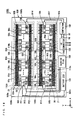
- Fig. 19 is a schematic plan view of the battery system according to the eighth embodiment.
- two FPC boards 50x are used in common for the two battery modules 110a, 110b of the module group 110A in the battery system 500C according to the present embodiment.
- two FPC boards 50x are used in common for the two battery modules 110c, 110d of the module group 110B. Details of the FPC boards 50x will be described.
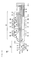
- Fig. 20 is a plan view of the FPC board 50x used in the battery system 500C according to the eighth embodiment.
- the FPC board 50x has a strip-shaped first region R11, a strip-shaped second region R12 and a rectangular connection region R13.
- the plurality of bus bars 40, 40a are attached to the first region R11, and the plurality of conductor lines 52 are provided in the first region R11.
- the plurality of conductor lines 52 are provided in the second region R12.
- the connection region R13 is used for connection of the conductor lines 52 provided in the first and second regions R11, R12 to the printed circuit board 21 ( Fig. 19 ).
- one lateral side is referred to as a first lateral side R11a
- the other lateral side on the opposite side to the first lateral side R11a is referred to as a second lateral side R11b
- one end side is referred to as a first end side R11c
- the other end side on the opposite side to the first end side R11c is referred to as a second end side R11d.
- the length (the length in a longitudinal direction) of the first region R11 is approximately twice the length in the X-direction (the direction in which the plurality of battery cells 10 line up) of one battery module.
- the length (the length in the longitudinal direction) of the second region R12 is approximately equal to the length in the X-direction (the direction in which the plurality of battery cells 10 line up) of one battery module.
- the length (the length in the longitudinal direction) of the second region R12 is approximately half the length (the length in the longitudinal direction) of the first region R11.
- the second region R12 is formed along the first lateral side R11a from substantially the center in the longitudinal direction of the first region R11 to the vicinity of the first end side R11c, thus being integrated with the first region R11.
- the boundary between the first region R11 and the second region R12, that is, part of the first lateral side R11a coincides with a bending line B1, described below.
- connection region R13 is formed along the first end side R11c of the first region R11, thus being integrated with the first region R11. Part of the connection region R13 projects sideward from the first region R11.
- the plurality of bus bars 40, 40a are attached to a surface of the first region R11 so as to line up at given spacings along the second lateral side R11b of the first region R11.
- the plurality of PTC elements 60 are attached to the surface of the first region R11 at the same spacings as the spacings between the plurality of bus bars 40, 40a. In this state, the FPC board 50x is bent at the bending line B1 (see the thick arrow).
- the FPC board 50x is valley-folded at the bending line B1, so that the second region R12 overlaps the first region R11.
- a region on the side of one end of the FPC board 50x including part of the first region R11 and the second region R12 is referred to as a one end region R21
- a region on the side of the other end of the FPC board 50x excluding the one end region R21 and the connection region R13 is referred to as an other end region R22.
- the plurality of conductor lines 52 extend parallel to one another along a longitudinal direction of the FPC board 50x from the plurality of PTC elements 60, respectively. Therefore, the number of the conductor lines 52 extending parallel to one another is increased in a region closer to the connection region R13. Thus, the number of the conductor lines 52 provided in the other end region R22 is smaller than the number of the conductor lines 52 provided in the one end region R21.
- the width (the length in a direction perpendicular to the longitudinal direction) of the other end region R22 is set smaller than the width (the length in the direction perpendicular to the longitudinal direction) of the one end region R21 in the FPC board 50x. Since the width and pitch of each of the plurality of conductor lines 52 need not be reduced, a short and heat generation in the conductor lines 52 can be sufficiently prevented. This reduces useless space in the other end region R22.
- the FPC boards 50x used in common for the two battery modules 110a, 110b are each provided such that the other end region R22 having the smaller width extends in the X-direction on an upper surface of the battery module 110a and the one end region R21 having the larger width extends in the X-direction on an upper surface of the battery module 110b including the detecting circuit 20.
- the FPC boards 50x used in common for the two battery modules 110c, 110d are each provided such that the other end region R22 having the smaller width extends in the X-direction on an upper surface of the battery module 110c and the one end region R21 having the larger width extends in the X-direction on an upper surface of the battery module 110d including the detecting circuit 20.
- the length of the second region R12 is approximately equal to the length in the X-direction (the direction in which the plurality of battery cells 10 line up) of the battery module in this example, the length of the second region R12 may be suitably changed according to the number of the conductor lines 52 and the arrangement thereof. That is, the second region R12 may be provided in a portion where the first region R11 cannot provide enough space for arranging increased number of the conductor lines 52, and may extend toward the vicinity of the connection region R13 ( Fig. 20 ).
- the FPC boards 50x are used in common for the two battery modules in the foregoing manner, thereby preventing the increased number of components and simplifying the configuration. Since the width and pitch of each of the plurality of conductor lines 52 need not be reduced, a short and heat generation in the conductor lines 52 can be sufficiently prevented. As a result, reduced cost, easier assembly and improved reliability of the entire battery system 500C are realized.
- Fig. 21 is a schematic plan view of the battery system according to the ninth embodiment.
- two FPC boards 50y are used in common for the two battery modules 110a, 110b of the module group 110A in the battery system 500D according to the present embodiment.
- two FPC boards 50y are used in common for the two battery modules 110c, 110d of the module group 110B. Details of the FPC boards 50y will be described.
- Fig. 22 is a plan view of the FPC board 50y used in the battery system 500D according to the ninth embodiment. Description is made of the FPC board 50y of Fig. 22 while referring to differences from the FPC board 50x of Fig. 20 .
- the first region R11 and the second region R12 have substantially the same widths (the lengths in the direction perpendicular to the longitudinal direction).
- the plurality of bus bars 40, 40a are attached to a surface of the first region R11 so as to line up at given spacings along the second lateral side R11b of the first region R11.
- the plurality of PTC elements 60 are attached to the surface of the first region R11 at the same spacings as the spacings between the plurality of bus bars 40, 40a.
- the conductor line 52 connected to each PTC element 60 extends from the first region R11 to the connection region R13 while not passing through the second region R12.
- the plurality of bus bars 40, 40a are attached to a surface of the second region R12 so as to line up at given spacings along one lateral side of the second region R12 (a lateral side on the opposite side to the bending line B1).
- the plurality of PTC elements 60 are attached to the surface of the second region R12 at the same spacings as the spacings between the plurality of bus bars 40, 40a.
- the conductor line 52 connected to each PTC element 60 extends from the second region R12 and passes through the first region R11 to reach the connection region R13.
- the FPC board 50y is bent at the bending line B1 (see the thick arrow).
- the second region R12 overlaps the first region R11.
- the first region R11 and the second region R12 have substantially the same widths. Therefore, the plurality of bus bars 40, 40a attached to the second region R12 are arranged along the second lateral side R11b of the first region R11 in the one end region R21. Accordingly, all the bus bars 40, 40a are arranged at the given spacings along the second lateral side R11b of the first region R11 in the one end region R21 and the other end region R22 (see 40, 40a indicated by the dotted lines in Fig. 22 ).
- the FPC boards 50y used in common for the two battery modules 110a, 110b are each provided such that the other end region R22 having the smaller width extends in the X-direction on an upper surface of the battery module 110a and the one end region R21 having the larger width extends in the X-direction on an upper surface of the battery module 110b including the detecting circuit 20.
- the FPC boards 50y used in common for the two battery modules 110c, 110d are each provided such that the other end region R22 having the smaller width extends in the X-direction on an upper surface of the battery module 110c and the one end region R21 having the larger width extends in the X-direction on an upper surface of the battery module 110d including the detecting circuit 20.
- the length of the second region R12 is approximately equal to the length in the X-direction (the direction in which the plurality of battery cells 10 line up) of the battery module
- the length of the second region R12 may be suitably changed according to the number of the conductor lines 52 and the arrangement thereof. That is, the second region R12 may be provided in a portion where the first region R11 cannot provide enough space for arranging increased number of the conductor lines 52, and may extend toward the vicinity of the connection region R13 ( Fig. 22 ).
- the FPC board 50y of Fig. 22 has fewer portions of intersection of the bending line B1 and the conductor lines 52 as compared with the FPC board 50x of Fig. 20 . Therefore, distortion occurs in fewer portions in the conductor lines 52 when the FPC board 50y is bent.
- the FPC boards 50y are used in common for the two battery modules in the foregoing manner, thereby preventing the increased number of components and simplifying the configuration. Since the width and pitch of each of the plurality of conductor lines 52 need not be reduced, a short and heat generation in the conductor lines 52 can be sufficiently prevented. As a result, reduced cost, easier assembly and improved reliability of the entire battery system 500D are realized.
- Each of module groups included in the battery system according to the tenth embodiment is mainly composed of two battery modules.
- the two battery modules used in the present embodiment each have a different configuration from that of the battery module 100 used in the first embodiment.
- Fig. 23 is an external perspective view showing one battery module used in the battery system according to the tenth embodiment
- Fig. 24 is a view showing one side surface of the battery module 120a of Fig. 23
- Fig. 25 is a view showing the other side surface of the battery module 120a of Fig. 23 .
- the battery module 120a includes a battery block BB, the printed circuit board 21 and the FPC boards 50a.
- the printed circuit board 21 is provided with the detecting circuit 20.
- the battery block BB is mainly composed of a plurality of cylindrical battery cells 1, and a pair of battery holders 90 holding the battery cells 1.
- the outer shape of each battery cell 1 is a cylindrical shape having opposed end surfaces (i.e., a columnar shape). A plus electrode is formed on one end surface of the battery cell 1, and a minus electrode is formed on the other end surface of the battery cell 1.
- the plurality of battery cells 1 are arranged parallel to one another such that the axial centers thereof are parallel to one another.
- the axial center of each battery cell 1 is parallel to the Y-direction.
- Half (six in this example) of the battery cells 1 are arranged on an upper stage, and the other half (six in this example) of the battery cells 1 are arranged on a lower stage.
- the plurality of battery cells 1 are arranged on the upper stage and the lower stage such that the positional relationship between the plus electrode and the minus electrode of each battery cell 1 is opposite to that of the adjacent battery cell 1.
- the plus electrode and the minus electrode of one battery cell 1 are respectively adjacent to the minus electrode and the plus electrode of the other battery cell 1 in the two adjacent battery cells 1.
- the battery holders 90 are each formed of a substantially rectangular plate-like member made of resin, for example.
- the battery holder 90 has one surface and the other surface.
- the one surface and the other surface of the battery holder 90 are referred to as an outer surface and an inner surface, respectively.
- the pair of battery holders 90 is arranged to sandwich the plurality of battery cells 1 therebetween.
- the one battery holder 90 is arranged to face one end surface of each battery cell 1, and the other battery holder 90 is arranged to face the other end surface of each battery cell 1.
- Holes are formed at four corners of each battery holder 90, and ends of stick-like fastening members 13 are inserted into the holes. Male threads are formed at the ends of the fastening members 13.
- the plurality of battery cells 1 and the pair of battery holders 90 are integrally fixed by attaching nuts N at the ends of the fastening members 13.
- Three holes 90h are formed at equal spacings in the battery holder 90 along its longitudinal direction. Conductor lines 52a are inserted through the holes 90h, respectively.
- the longitudinal direction of the battery holder 90 is parallel to the X-direction in this example.
- a virtual rectangular parallelepiped surrounds the battery block BB.
- the rectangular parallelepiped has six virtual planes, a virtual plane facing outer peripheral surfaces of the respective battery cells 1 positioned on the upper stage and the lower stage at one end in the X-direction is referred to as a side surface Ea of the battery block BB, and a virtual plane facing outer peripheral surfaces of the respective battery cells 1 positioned on the upper stage and the lower stage at the other end in the X-direction is referred to as a side surface Eb of the battery block BB.
- a virtual plane facing one end surfaces in the Y-direction of the plurality of battery cells 1 is referred to as a side surface Ec of the battery block BB
- a virtual plane facing the other end surfaces in the Y-direction of the plurality of battery cells 1 is referred to as a side surface Ed of the battery block BB.
- a virtual plane facing outer peripheral surfaces of the plurality of battery cells 1 on the upper stage is referred to as a side surface Ee of the battery block BB
- a virtual plane facing outer peripheral surfaces of the plurality of battery cells 1 on the lower stage is referred to as a side surface Ef of the battery block BB.
- the side surfaces Ea, Eb of the battery block BB are perpendicular to a direction in which the plurality of battery cells 1 on the upper or lower stage are arranged (the X-direction). That is, the side surfaces Ea, Eb of the battery block BB are parallel to the Y-Z plane while facing each other.
- the side surfaces Ec, Ed of the battery block BB are perpendicular to an axial direction of each battery cell 1 (the Y-direction). That is, the side surfaces Ec, Ed of the battery block BB are parallel to the X-Z plane while facing each other.
- the side surfaces Ee, Ef of the battery block BB are parallel to the direction in which the plurality of battery cells 1 on the upper or lower stage are arranged (the X-direction) and the axial direction of each battery cell 1 (the Y-direction). That is, the side surfaces Ee, Ef of the battery block BB are parallel to the X-Y plane while facing each other.
- One of the plus electrode and the minus electrode of each battery cell 1 is arranged at the side surface Ec of the battery block BB, and the other is arranged at the side surface Ed of the battery block BB.
- the plurality of battery cells 1 are connected in series through the plurality of bus bars 40, 40a and hexagon head bolts 14. More specifically, a plurality of holes corresponding to the plurality of battery cells 1 on the upper stage and the lower stage are formed in each of the battery holders 90. The plus electrode and the minus electrode of each battery cell 1 are fitted in the corresponding holes formed in the pair of battery holders 90. This causes the plus electrode and the minus electrode of each battery cell 1 to project from the outer surfaces of the pair of battery holders 90.
- the battery cells 1 are arranged such that the positional relationship between the plus electrode and the minus electrode of each battery cell 1 is opposite to that of the adjacent battery cell 1 in the battery block BB. Therefore, in two adjacent battery cells 1, the plus electrode of one battery cell 1 is in close proximity to the minus electrode of the other battery cell 1, and the minus electrode of the one battery cel1 1 is in close proximity to the plus electrode of the other battery cell 1. In this state, the bus bar 40 is attached to the plus electrode and the minus electrode being in close proximity to each other such that the plurality of battery cells 1 are connected in series.
- the closest battery cell 1 to the side surface Ea to the closest battery cell 1 to the side surface Eb of the six battery cells 1 arranged on the upper stage of the battery block BB are referred to as first to sixth battery cells 1.
- the closest battery cell 1 to the side surface Eb to the closest battery cell 1 to the side surface Ea of the six battery cells 1 arranged on the lower stage of the battery block BB are referred to as seventh to twelfth battery cells 1.
- the common bus bar 40 is attached to the minus electrode of the first battery cell 1 and the plus electrode of the second battery cell 1.
- the common bus bar 40 is attached to the minus electrode of the second battery cell 1 and the plus electrode of the third battery cell 1.
- the common bus bar 40 is attached to the minus electrode of each of the odd-numbered battery cells 1 and the plus electrode of each of the even-numbered battery cells 1 adjacent thereto.
- the common bus bar 40 is attached to the minus electrode of each of the even-numbered battery cells 1 and the plus electrode of each of the odd-numbered battery cells 1 adjacent thereto.
- the bus bars 40a for connecting power lines from the exterior are respectively attached to the plus electrode of the first battery cell 1 and the minus electrode of the twelfth battery cell 1.
- the printed circuit board 21 including the detecting circuit 20 is attached to the side surface Ea of the battery block BB.
- the long-sized FPC board 50a is provided to extend from the side surface Ec to the side surface Ea of the battery block BB.
- the long-sized FPC board 50a is provided to extend from the side surface Ed to the side surface Ea of the battery block BB.
- the above-mentioned FPC boards 50a have substantially the same configuration as the FPC board 50 used in the first to eighth embodiments.
- the PTC elements 60 are arranged in close proximity to the plurality of bus bars 40, 40a, respectively, on each of the FPC boards 50a.
- the one FPC board 50a is arranged to extend in the direction in which the plurality of battery cells 1 are arranged (the X-direction) at the center of the side surface Ec of the battery block BB.
- the FPC board 50a is connected in common to the plurality of bus bars 40.
- the other FPC board 50a is arranged to extend in the direction in which the plurality of battery cells 1 are arranged (the X-direction) at the center of the side surface Ed of the battery block BB.
- the FPC board 50a is connected in common to the plurality of bus bars 40, 40a.
- the FPC board 50a on the side surface Ec is bent at a right angle at one end of the side surface Ec of the battery block BB toward the side surface Ea to be connected to the printed circuit board 21.
- the FPC board 50a on the side surface Ed is bent at a right angle at one end of the side surface Ed of the battery block BB toward the side surface Ea to be connected to the printed circuit board 21.
- the plurality of thermistors 11 are attached to the battery block BB.
- the thermistors 11 are connected to the FPC boards 50a through the conductor lines 52a.
- the bus bars 40, 40a and the thermistors 11 of the battery module 120a are electrically connected to the printed circuit board 21 through the conductor lines formed in the FPC boards 50a.
- Fig. 26 is an external perspective view showing the other battery module used in the battery system according to the tenth embodiment.
- the printed circuit board 21 is not attached to a side surface Ea of a battery block BB in the battery module 120b. Therefore, the battery module 120b does not include the detecting circuit 20.
- the length of each of the two FPC boards 50b provided on side surfaces Ec, Ed of the battery block BB is approximately twice the length of each of the two FPC boards 50a of the battery module 120a.
- Fig. 27 is an external perspective view showing the arrangement of the module group included in the battery system according to the tenth embodiment.
- the two battery modules 120a, 120b are arranged in close proximity to each other while the side surface Eb of the battery block BB of the battery module 120a faces the side surface Ea of the battery block BB of the battery module 120b in the module group 120A. Accordingly, the battery modules 120a, 120b are arranged to line up along the direction in which the plurality of battery cells 1 are arranged (the X-direction).
- the minus electrode of the sixth battery cell 1 of the battery module 120a and the plus electrode of the first battery cell 1 of the battery module 120b are connected to each other through the strip-shaped bus bar 551.
- the bus bar 551 corresponds to the power supply line 501 of Fig. 1 .
- the minus electrode of the twelfth battery cell 1 of the battery module 120b and the plus electrode of the seventh battery cell 1 of the battery module 120a are connected to each other through the strip-shaped bus bar 551. Accordingly, all the battery cells 1 of the battery modules 120a, 120b are connected in series.
- the detecting circuit 20 and the printed circuit board 21 provided on the side surface Ea of the battery block BB of the battery module 120a are used in common for the two battery modules 120a, 120b.
- the one FPC board 50a of the battery module 120a is provided to extend from the side surface Ec to the side surface Ea of the battery block BB to be connected to the printed circuit board 21.
- the other FPC board 50a of the battery module 120a is provided to extend from the side surface Ed to the side surface Ea of the battery block BB to be connected to the printed circuit board 21.
- the one FPC board 50b of the battery module 120b extends in the X-direction on the side surface Ec of the battery module 120b, and further extends in the X-direction to overlap the FPC board 50a on the side surface Ec of the battery module 120a to be connected to the common printed circuit board 21.
- the other FPC board 50b of the battery module 120b extends in the X-direction on the side surface Ed of the battery module 120b, and further extends in the X-direction to overlap the FPC board 50a on the side surface Ed of the battery module 120a to be connected to the common printed circuit board 21.
- the four FPC boards 50a, 50b are connected to the printed circuit board 21.
- the detecting circuit 20 can be used in common for the two battery modules 120a, 120b even though the battery modules 120a, 120b are composed of the battery cells 1 each having the columnar shape.
- the number of the detecting circuits 20 can be reduced and the wiring for communication can be simplified. Accordingly, reduced cost, easier assembly and improved reliability of the entire battery system are realized.
- the electric vehicle according to the present embodiment includes the battery system according to any of the first to tenth embodiments.
- An electric automobile is described as one example of the electric vehicle in the following paragraphs.
- Fig. 28 is a block diagram showing the configuration of an electric automobile including the battery system 500 of Fig. 1 .
- the electric automobile 600 according to the present embodiment includes the main controller 300 and the battery system 500 of Fig. 1 , a power converter 601, a motor 602, a drive wheel 603, an accelerator system 604, a brake system 605, and a rotational speed sensor 606.
- the motor 602 is an alternate current (AC) motor
- the power converter 601 includes an inverter circuit.
- the battery system 500 is connected to the motor 602 via the power converter 601 while being connected to the main controller 300.
- the main controller 300 is provided with the charged capacity of the plurality of battery modules 100 ( Fig. 1 ) and the value of the current flowing through the battery modules 100 from the battery ECU 101 ( Fig. 1 ) constituting the battery system 500.
- each of the accelerator system 604, the brake system 605 and the rotational speed sensor 606 is connected to the main controller 300.
- the main controller 300 is composed of a CPU and a memory or composed of a microcomputer, for example.
- the accelerator system 604 includes an accelerator pedal 604a included in the electric automobile 600 and an accelerator detector 604b that detects an operation amount (depression amount) of the accelerator pedal 604a.
- the accelerator detector 604b detects the operation amount of the accelerator pedal 604a. Note that a state of the accelerator pedal 604a when not being operated by the driver is set as a reference. The detected operation amount of the accelerator pedal 604a is given to the main controller 300.
- the brake system 605 includes a brake pedal 605a provided in the electric automobile 600 and a brake detector 605b that detects an operation amount (depression amount) of the brake pedal 605a by the driver.
- the operation amount is detected by the brake detector 605b.
- the detected operation amount of the brake pedal 605a is given to the main controller 300.
- the rotational speed sensor 606 detects a rotational speed of the motor 602. The detected rotational speed is given to the main controller 300.
- the charged capacity of the battery modules 100, the value of the current flowing through the battery modules 100, the operation amount of the accelerator pedal 604a, the operation amount of the brake pedal 605a and the rotational speed of the motor 602 are given to the main controller 300.
- the main controller 300 controls charge / discharge of the battery modules 100 and power conversion by the power converter 601 based on the information.
- Electric power generated by the battery modules 100 is supplied from the battery system 500 to the power converter 601 at the time of starting and accelerating the electric automobile 600 based on the accelerator operation, for example.
- the main controller 300 calculates a torque (commanded torque) to be transmitted to the drive wheel 603 based on the given operation amount of the accelerator pedal 604a, and gives a control signal based on the commanded torque to the power converter 601.
- the power converter 601 receives the control signal, and then converts the electric power supplied from the battery system 500 into electric power (driving power) required for driving the drive wheel 603. Accordingly, the driving power converted by the power converter 601 is supplied to the motor 602, and the torque of the motor 602 based on the driving power is transmitted to the drive wheel 603.
- the motor 602 functions as a power generation system at the time of decelerating the electric automobile 600 based on the brake operation.
- the power converter 601 converts regenerated electric power generated by the motor 602 to electric power suitable for charging the battery modules 100, and supplies the electric power to the battery module 100. This causes the battery modules 100 to be charged.
- the electric automobile 600 according to the present embodiment is provided with the battery system according to any of the first to tenth embodiments. Accordingly, the complicated configuration and increased cost can be suppressed while the capacity can be increased in the battery system. This allows for increased driving time and reduced cost of the electric vehicle.
- the detecting circuit 20 is an example of a voltage detector
- the end surface frame 92 and the holder 20H are examples of a holding member
- the bus bars 40, 40a are examples of a connecting member
- the FPC board 50 is an example of a flexible member
- the conductor lines 51, 52 are examples of a voltage detection line.
- the X-direction is an example of a first direction
- the Y-direction is an example of a second direction
- the battery modules 110a, 110b are examples of a first battery module
- the battery modules 110c, 110d are examples of a second battery module.
- the module groups 110A, 110B are examples of first and second battery module groups, respectively, and the detecting circuit 20 of the module group 110A is an example of a first voltage detector, and the detecting circuit 20 of the module group 110B is an example of a second voltage detector.
Applications Claiming Priority (2)
| Application Number | Priority Date | Filing Date | Title |
|---|---|---|---|
| JP2009178222 | 2009-07-30 | ||
| JP2010164500A JP2011049155A (ja) | 2009-07-30 | 2010-07-22 | バッテリシステムおよびそれを備えた電動車両 |
Publications (1)
| Publication Number | Publication Date |
|---|---|
| EP2290733A1 true EP2290733A1 (de) | 2011-03-02 |
Family
ID=42988358
Family Applications (1)
| Application Number | Title | Priority Date | Filing Date |
|---|---|---|---|
| EP10251325A Withdrawn EP2290733A1 (de) | 2009-07-30 | 2010-07-26 | Batteriesystem und dieses enthaltendes Elektrofahrzeug |
Country Status (5)
| Country | Link |
|---|---|
| US (1) | US20110027634A1 (de) |
| EP (1) | EP2290733A1 (de) |
| JP (1) | JP2011049155A (de) |
| KR (1) | KR20110013324A (de) |
| CN (1) | CN101989670A (de) |
Cited By (6)
| Publication number | Priority date | Publication date | Assignee | Title |
|---|---|---|---|---|
| WO2012152444A1 (de) * | 2011-05-12 | 2012-11-15 | Audi Ag | Hv-batterie, insbesondere traktionsbatterie für ein fahrzeug |
| WO2013015446A1 (en) * | 2011-07-28 | 2013-01-31 | Yazaki Corporation | Battery pack |
| WO2013015390A1 (en) * | 2011-07-22 | 2013-01-31 | Yazaki Corporation | Structure for attaching service plug |
| EP2645450A1 (de) * | 2012-03-26 | 2013-10-02 | Leclanché S.A. | Zuverlässige und effiziente Verbindung für Batterien |
| WO2013147659A1 (en) * | 2012-03-30 | 2013-10-03 | Alelion Batteries Ab | Battery pack |
| US10923773B2 (en) | 2017-12-14 | 2021-02-16 | Te Connectivity Germany Gmbh | Contacting unit for electrically contacting at least one electronics segment of an electronics module and method |
Families Citing this family (24)
| Publication number | Priority date | Publication date | Assignee | Title |
|---|---|---|---|---|
| EP2636087A4 (de) * | 2010-11-05 | 2014-04-16 | Alelion Batteries Ab | Batterieanordnung |
| JP2012226969A (ja) * | 2011-04-19 | 2012-11-15 | Jst Mfg Co Ltd | 電池モジュールのハーネス及び電池モジュール |
| DE102011076981B4 (de) * | 2011-06-06 | 2021-08-26 | Robert Bosch Gmbh | Batteriesystem, Kraftfahrzeug mit diesem Batteriesystem und Verfahren zur Herstellung einer Betriebsbereitschaft bei einem Kraftfahrzeug mit diesem Batteriesystem |
| JP5803405B2 (ja) | 2011-08-10 | 2015-11-04 | 株式会社オートネットワーク技術研究所 | バスバーカバー、及びカバー付きバスバー |
| JP5648602B2 (ja) * | 2011-08-22 | 2015-01-07 | 株式会社オートネットワーク技術研究所 | 電池配線モジュール |
| US9327657B2 (en) * | 2011-08-31 | 2016-05-03 | Toyota Jidosha Kabushiki Kaisha | Bus bar module, vehicle power source apparatus, and vehicle |
| JP5811796B2 (ja) * | 2011-11-18 | 2015-11-11 | 株式会社デンソー | 組電池 |
| JP5630431B2 (ja) * | 2011-12-13 | 2014-11-26 | 株式会社デンソー | 組電池 |
| JP2014093864A (ja) * | 2012-11-02 | 2014-05-19 | Toyota Industries Corp | 電池 |
| US20140141287A1 (en) * | 2012-11-19 | 2014-05-22 | Delphi Technologies, Inc. | Battery pack and battery control module |
| WO2014194410A1 (en) * | 2013-06-06 | 2014-12-11 | Timeless Technologies (2007) Inc. | Method and system for providing a treatment protocol |
| US10090566B2 (en) * | 2013-08-27 | 2018-10-02 | Robert Bosch Gmbh | Solid state battery with offset geometry |
| DE102013221870B4 (de) * | 2013-10-28 | 2021-09-30 | Te Connectivity Germany Gmbh | Verbindungsanordnung zur Verbindung mindestens einer als Zelle ausgestalteten Spannungsquelle und/oder -senke mit einem externen elektrischen Bauelement und elektrische Anordnung umfassend eine Verbindungsanordnung |
| JP6363645B2 (ja) | 2016-03-09 | 2018-07-25 | 株式会社東芝 | 電池モジュール、電池、蓄電池、及び電気装置 |
| JP6469062B2 (ja) * | 2016-09-30 | 2019-02-13 | 株式会社オートネットワーク技術研究所 | 接続モジュール |
| US20180097322A1 (en) * | 2016-09-30 | 2018-04-05 | Faraday&Future Inc. | Flexible bus bar |
| CN107037254B (zh) * | 2017-01-23 | 2023-04-21 | 中国工程物理研究院应用电子学研究所 | 一种用于真空二极管电压测量的D-dot探头 |
| JP6350721B1 (ja) * | 2017-06-12 | 2018-07-04 | 株式会社オートネットワーク技術研究所 | 外部接続バスバー保持モジュール、接続モジュールおよび蓄電モジュール |
| JP7004197B2 (ja) * | 2017-09-22 | 2022-01-21 | 株式会社オートネットワーク技術研究所 | 電気接続部材 |
| CN111599955B (zh) * | 2019-03-22 | 2024-04-30 | 骆驼集团新能源电池有限公司 | 一种无模组类铝壳电池模组及铝壳电池 |
| CN209747612U (zh) | 2019-06-28 | 2019-12-06 | 江苏时代新能源科技有限公司 | 电池模组 |
| JP2021068696A (ja) * | 2020-06-12 | 2021-04-30 | 株式会社オートネットワーク技術研究所 | 配線モジュール及び蓄電モジュール |
| JP7229648B2 (ja) * | 2020-07-29 | 2023-02-28 | 矢崎総業株式会社 | バッテリ接続モジュール |
| US11769935B1 (en) * | 2022-10-12 | 2023-09-26 | Lunar Energy, Inc. | Wiring harness for energy storage system |
Citations (4)
| Publication number | Priority date | Publication date | Assignee | Title |
|---|---|---|---|---|
| JPH08162171A (ja) | 1994-12-05 | 1996-06-21 | Matsushita Electric Ind Co Ltd | 組電池の監視装置 |
| US20080050645A1 (en) * | 2006-07-31 | 2008-02-28 | Hitachi Vehicle Energy, Ltd. | Cell controller, battery module and power supply system |
| US20080053716A1 (en) * | 2006-02-09 | 2008-03-06 | Scheucher Karl F | Refuelable battery-powered electric vehicle |
| US20080286639A1 (en) * | 2007-05-16 | 2008-11-20 | Sony Corporation | Battery pack |
Family Cites Families (5)
| Publication number | Priority date | Publication date | Assignee | Title |
|---|---|---|---|---|
| JP5254568B2 (ja) * | 2007-05-16 | 2013-08-07 | 日立ビークルエナジー株式会社 | セルコントローラ、電池モジュールおよび電源システム |
| JP4447625B2 (ja) * | 2007-06-25 | 2010-04-07 | 矢崎総業株式会社 | 電源装置 |
| JP2009059663A (ja) * | 2007-09-03 | 2009-03-19 | Honda Motor Co Ltd | 蓄電池ユニット |
| JP5223607B2 (ja) * | 2008-11-10 | 2013-06-26 | 株式会社デンソー | 電池パックの高電圧検出モジュール装置 |
| JP5472570B2 (ja) * | 2009-01-07 | 2014-04-16 | 三菱自動車工業株式会社 | 二次電池の電圧検出装置 |
-
2010
- 2010-07-22 JP JP2010164500A patent/JP2011049155A/ja active Pending
- 2010-07-26 EP EP10251325A patent/EP2290733A1/de not_active Withdrawn
- 2010-07-27 US US12/844,563 patent/US20110027634A1/en not_active Abandoned
- 2010-07-29 CN CN2010102418447A patent/CN101989670A/zh active Pending
- 2010-07-30 KR KR1020100073987A patent/KR20110013324A/ko not_active Application Discontinuation
Patent Citations (4)
| Publication number | Priority date | Publication date | Assignee | Title |
|---|---|---|---|---|
| JPH08162171A (ja) | 1994-12-05 | 1996-06-21 | Matsushita Electric Ind Co Ltd | 組電池の監視装置 |
| US20080053716A1 (en) * | 2006-02-09 | 2008-03-06 | Scheucher Karl F | Refuelable battery-powered electric vehicle |
| US20080050645A1 (en) * | 2006-07-31 | 2008-02-28 | Hitachi Vehicle Energy, Ltd. | Cell controller, battery module and power supply system |
| US20080286639A1 (en) * | 2007-05-16 | 2008-11-20 | Sony Corporation | Battery pack |
Cited By (10)
| Publication number | Priority date | Publication date | Assignee | Title |
|---|---|---|---|---|
| WO2012152444A1 (de) * | 2011-05-12 | 2012-11-15 | Audi Ag | Hv-batterie, insbesondere traktionsbatterie für ein fahrzeug |
| US8975774B2 (en) | 2011-05-12 | 2015-03-10 | Audi Ag | HV-battery, in particular traction battery for a vehicle |
| WO2013015390A1 (en) * | 2011-07-22 | 2013-01-31 | Yazaki Corporation | Structure for attaching service plug |
| US9299975B2 (en) | 2011-07-22 | 2016-03-29 | Yazaki Corporation | Structure for attaching service plug |
| WO2013015446A1 (en) * | 2011-07-28 | 2013-01-31 | Yazaki Corporation | Battery pack |
| US9947911B2 (en) | 2011-07-28 | 2018-04-17 | Yazaki Corporation | Battery pack |
| EP2645450A1 (de) * | 2012-03-26 | 2013-10-02 | Leclanché S.A. | Zuverlässige und effiziente Verbindung für Batterien |
| WO2013147659A1 (en) * | 2012-03-30 | 2013-10-03 | Alelion Batteries Ab | Battery pack |
| US9837683B2 (en) | 2012-03-30 | 2017-12-05 | Alelion Energy Systems Ab | Battery pack |
| US10923773B2 (en) | 2017-12-14 | 2021-02-16 | Te Connectivity Germany Gmbh | Contacting unit for electrically contacting at least one electronics segment of an electronics module and method |
Also Published As
| Publication number | Publication date |
|---|---|
| CN101989670A (zh) | 2011-03-23 |
| JP2011049155A (ja) | 2011-03-10 |
| US20110027634A1 (en) | 2011-02-03 |
| KR20110013324A (ko) | 2011-02-09 |
Similar Documents
| Publication | Publication Date | Title |
|---|---|---|
| EP2290733A1 (de) | Batteriesystem und dieses enthaltendes Elektrofahrzeug | |
| EP2325920A2 (de) | Batteriesystem und dieses enthaltendes Elektrofahrzeug | |
| US20110104521A1 (en) | Battery system and electric vehicle including the same | |
| US20110159336A1 (en) | Battery system and electric vehicle including the same | |
| US20120161677A1 (en) | Battery module, battery system and electrically driven vehicle | |
| US20110156618A1 (en) | Battery system and electric vehicle including the same | |
| US20110024205A1 (en) | Battery module, battery system and electric vehicle | |
| JP6160729B2 (ja) | バッテリモジュール | |
| US20100271223A1 (en) | Battery module, battery system, and electric vehicle | |
| US20100271036A1 (en) | Battery module, battery system and electric vehicle | |
| US11682797B2 (en) | Systems and methods for providing individual battery cell circuit protection | |
| US20120019061A1 (en) | Battery module, battery system and electric vehicle | |
| WO2011105095A1 (ja) | バッテリモジュール、バッテリシステム、電動車両、移動体、電力貯蔵装置、電源装置および電気機器 | |
| JP2012028186A (ja) | バッテリモジュール、バッテリシステムおよび電動車両 | |
| WO2012042913A1 (ja) | バッテリモジュール、それを備えたバッテリシステム、電動車両、移動体、電力貯蔵装置、電源装置および電気機器 | |
| KR20120106834A (ko) | 배터리 모듈, 그것을 구비한 전동 차량, 이동체, 배터리 시스템, 전력 저장 장치 및 전원 장치 | |
| JPWO2011108680A1 (ja) | 薄形電池モジュール及びこれを用いた組電池 | |
| US10615615B2 (en) | Monitoring device | |
| EP2325919A2 (de) | Batteriesystem und dieses enthaltendes Elektrofahrzeug | |
| WO2012029319A1 (ja) | バッテリモジュール、バッテリシステム、電動車両、移動体、電力貯蔵装置、電源装置および電気機器 | |
| JP2011119235A (ja) | バッテリシステムおよびそれを備えた電動車両 | |
| KR20110048001A (ko) | 배터리 모듈, 배터리 시스템 및 그를 구비한 전동 차량 |
Legal Events
| Date | Code | Title | Description |
|---|---|---|---|
| PUAI | Public reference made under article 153(3) epc to a published international application that has entered the european phase |
Free format text: ORIGINAL CODE: 0009012 |
|
| AK | Designated contracting states |
Kind code of ref document: A1 Designated state(s): AL AT BE BG CH CY CZ DE DK EE ES FI FR GB GR HR HU IE IS IT LI LT LU LV MC MK MT NL NO PL PT RO SE SI SK SM TR |
|
| AX | Request for extension of the european patent |
Extension state: BA ME RS |
|
| 17P | Request for examination filed |
Effective date: 20110810 |
|
| 17Q | First examination report despatched |
Effective date: 20120419 |
|
| GRAP | Despatch of communication of intention to grant a patent |
Free format text: ORIGINAL CODE: EPIDOSNIGR1 |
|
| INTG | Intention to grant announced |
Effective date: 20131004 |
|
| STAA | Information on the status of an ep patent application or granted ep patent |
Free format text: STATUS: THE APPLICATION IS DEEMED TO BE WITHDRAWN |
|
| 18D | Application deemed to be withdrawn |
Effective date: 20140201 |