EP2290271A1 - Dichtungsanordnung und deren Verwendung - Google Patents
Dichtungsanordnung und deren Verwendung Download PDFInfo
- Publication number
- EP2290271A1 EP2290271A1 EP09011034A EP09011034A EP2290271A1 EP 2290271 A1 EP2290271 A1 EP 2290271A1 EP 09011034 A EP09011034 A EP 09011034A EP 09011034 A EP09011034 A EP 09011034A EP 2290271 A1 EP2290271 A1 EP 2290271A1
- Authority
- EP
- European Patent Office
- Prior art keywords
- ring
- sealed
- filter
- sealing
- arrangement according
- Prior art date
- Legal status (The legal status is an assumption and is not a legal conclusion. Google has not performed a legal analysis and makes no representation as to the accuracy of the status listed.)
- Granted
Links
- 239000000314 lubricant Substances 0.000 claims abstract description 17
- 239000010687 lubricating oil Substances 0.000 claims abstract description 5
- 238000007789 sealing Methods 0.000 claims description 72
- 238000009434 installation Methods 0.000 claims description 8
- 239000003921 oil Substances 0.000 claims description 8
- 230000005540 biological transmission Effects 0.000 claims description 6
- 239000004745 nonwoven fabric Substances 0.000 abstract 1
- 239000000835 fiber Substances 0.000 description 4
- 239000012535 impurity Substances 0.000 description 4
- 239000002245 particle Substances 0.000 description 4
- 239000000498 cooling water Substances 0.000 description 3
- 239000000463 material Substances 0.000 description 3
- 230000000712 assembly Effects 0.000 description 2
- 238000000429 assembly Methods 0.000 description 2
- 239000000356 contaminant Substances 0.000 description 2
- 238000011109 contamination Methods 0.000 description 2
- 230000000694 effects Effects 0.000 description 2
- 229920001971 elastomer Polymers 0.000 description 2
- 239000000806 elastomer Substances 0.000 description 2
- 239000004744 fabric Substances 0.000 description 2
- 238000001914 filtration Methods 0.000 description 2
- 239000002184 metal Substances 0.000 description 2
- 238000011144 upstream manufacturing Methods 0.000 description 2
- 239000011248 coating agent Substances 0.000 description 1
- 238000000576 coating method Methods 0.000 description 1
- 238000002485 combustion reaction Methods 0.000 description 1
- 230000001419 dependent effect Effects 0.000 description 1
- 239000013536 elastomeric material Substances 0.000 description 1
- 230000020169 heat generation Effects 0.000 description 1
- 238000003475 lamination Methods 0.000 description 1
- 238000005461 lubrication Methods 0.000 description 1
- 230000002093 peripheral effect Effects 0.000 description 1
- 230000035699 permeability Effects 0.000 description 1
- 229920000728 polyester Polymers 0.000 description 1
- 230000001681 protective effect Effects 0.000 description 1
- 230000003068 static effect Effects 0.000 description 1
Images

Classifications
-
- F—MECHANICAL ENGINEERING; LIGHTING; HEATING; WEAPONS; BLASTING
- F16—ENGINEERING ELEMENTS AND UNITS; GENERAL MEASURES FOR PRODUCING AND MAINTAINING EFFECTIVE FUNCTIONING OF MACHINES OR INSTALLATIONS; THERMAL INSULATION IN GENERAL
- F16J—PISTONS; CYLINDERS; SEALINGS
- F16J15/00—Sealings
- F16J15/002—Sealings comprising at least two sealings in succession
-
- F—MECHANICAL ENGINEERING; LIGHTING; HEATING; WEAPONS; BLASTING
- F16—ENGINEERING ELEMENTS AND UNITS; GENERAL MEASURES FOR PRODUCING AND MAINTAINING EFFECTIVE FUNCTIONING OF MACHINES OR INSTALLATIONS; THERMAL INSULATION IN GENERAL
- F16J—PISTONS; CYLINDERS; SEALINGS
- F16J15/00—Sealings
- F16J15/16—Sealings between relatively-moving surfaces
- F16J15/32—Sealings between relatively-moving surfaces with elastic sealings, e.g. O-rings
- F16J15/3248—Sealings between relatively-moving surfaces with elastic sealings, e.g. O-rings provided with casings or supports
- F16J15/3252—Sealings between relatively-moving surfaces with elastic sealings, e.g. O-rings provided with casings or supports with rigid casings or supports
-
- F—MECHANICAL ENGINEERING; LIGHTING; HEATING; WEAPONS; BLASTING
- F16—ENGINEERING ELEMENTS AND UNITS; GENERAL MEASURES FOR PRODUCING AND MAINTAINING EFFECTIVE FUNCTIONING OF MACHINES OR INSTALLATIONS; THERMAL INSULATION IN GENERAL
- F16J—PISTONS; CYLINDERS; SEALINGS
- F16J15/00—Sealings
- F16J15/16—Sealings between relatively-moving surfaces
- F16J15/32—Sealings between relatively-moving surfaces with elastic sealings, e.g. O-rings
- F16J15/3268—Mounting of sealing rings
Definitions
- the invention relates to a sealing arrangement and its use, wherein the sealing arrangement comprises a sealing ring and a filter ring made of filter fleece, which is associated with the sealing ring adjacent to the space to be sealed facing side with axial spacing.
- the sealing arrangement comprises a cooling water pump seal for an internal combustion engine in which the main seal sliding against the shaft is preceded by a protective seal on the cooling water side, which consists of a filter fleece, wherein the filter fleece is fastened to the housing carrying the main seal.
- the filter fleece has a basis weight of 60 to 900 g / m 2 and a thickness of 1 mm to 4 mm and is preferably made of polyester fibers.
- the invention has for its object to develop a seal assembly for other media to be sealed as cooling water.
- seal assembly should be used differently. This object is achieved by a use according to claim 10.
- a sealing arrangement comprising a sealing ring and a filter ring made of filter fleece, which is associated with the sealing ring on the side facing a space to be sealed adjacent with axial spacing, wherein the space to be sealed is at least partially filled with a lubricant.
- sealing rings which seal a lubricant are lubricated by the lubricant to be sealed so that they remain as consistently good as possible during the longest possible service life Have useful properties; The wear of the sealing ring should be reduced to a minimum by lubrication. However, this presupposes that the lubricant to be sealed has, if possible, no impurities, in particular no abrasive impurities, which could damage the sealing ring.
- the sealing ring and the filter ring can enclose the sealed surface of a machine element to be sealed fitting.
- the sealing ring surrounds the surface to be sealed under elastic prestressing. It can be provided that the sealing ring and the filter ring, each with respect to the surface to be sealed, each have an overlap. For some applications, it may be useful if the filter ring has no overlap.
- the sealing ring may be formed, for example, as a radial shaft seal and having a dynamically stressed sealing lip, which is arched axially in the direction of the space to be sealed.
- the sealing lip can be pressed sealingly against the surface to be sealed by an annular helical spring, which surrounds the sealing lip radially on the outer peripheral side.
- an annular helical spring which surrounds the sealing lip radially on the outer peripheral side.
- the filter ring of filter fleece is preferably according to the sealing ring also axially bulged in the direction of the space to be sealed, wherein the Covering the filter ring is only so low to ensure a circumferential contact with the surface to be sealed. Due to the low coverage of the filter ring and the friction loss is very low and thus also the unwanted generation of heat.
- the sealing ring and the filter ring can each be fixed to a support body and each form a preassemblable unit with the associated supporting bodies. It is advantageous that different sealing rings can be combined with different filter rings by this modular design.
- the support body of the respective rings are preferably made of a tough material, such as sheet metal or a polymeric material.
- the functional properties of the sealing ring and the functional properties of the filter ring can be adapted to the respective application. If the particle load within the lubricant to be sealed is, for example, particularly large and / or the material of which the sealing ring is made is particularly susceptible to wear, a filter ring made of a filter fleece can be provided, which has a particularly good filtering effect.
- the filter web can have a significantly lower filtering effect and thus a higher permeability of the lubricant to be sealed to the sealing ring.
- the filter ring and the support body can be glued together and / or jammed.
- the filter ring and the sealing ring can be glued together.
- the two preassemblable units are connected to each other and form another unit.
- the further unit is easy to handle because it includes the sealing ring and the filter ring. The risk of assembly errors is thereby limited to a minimum.
- the preassemblable units are arranged adjacent to each other with axial spacing in the installation space. It is advantageous that in the installation space axially between the preassemblable units a supply line for fresh oil can be arranged.
- the fresh oil is promoted after its introduction into the seal assembly in the direction of the space to be sealed, past the bulging filter ring in the space to be sealed.
- the filter ring then acts as a kind of check valve. After the fresh oil has entered the space to be sealed, the filter ring rests against the surface to be sealed in order to prevent a direct and unfiltered passage of contaminated lubricant from the space to be sealed back to the sealing ring.
- the filter fleece of the filter ring is preferably laminated. As a result, a better binding of the filter mat is achieved, and the rupture of fibers during the intended use of the seal assembly is minimized. This is important in that a burst of fiber could jeopardize the sealing mechanism of the sealing ring because, for example, a return device of the sealing ring, which may optionally be provided to backfill medium to be sealed in the direction of the space to be sealed, may be rendered inoperable by broken fibers.
- a particularly good binding of the filter fleece is preferably achieved by an NBR lamination.
- the lubricant may be formed by a lubricating oil.
- the sealing arrangement described above can be used in transmissions or axles of commercial vehicles, especially in transmissions or axles of fast vans.
- the lubricating oil is often more contaminated.
- the sealing ring is protected by the upstream in the direction of the sealed space filter ring particularly reliable.
- the seal arrangement can also be used in stationary gearboxes.
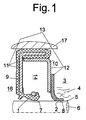
- a sealing arrangement which comprises a sealing ring 1 and a filter ring 2, wherein the filter ring 2 consists of a filter fleece.
- the filter ring 2 is assigned to the sealing ring 1 on the side facing the sealed space 3 with an axial distance adjacent, wherein the sealed space 3 is arranged in the embodiments shown here in a transmission or in an axle of a motor vehicle.
- a lubricant 4 for example, a lubricating oil, arranged, which is sealed from the environment 16.
- the sealed machine element 6 is an axis or a shaft in the embodiments shown here, wherein both the sealing ring 1 and the filter ring 2 enclose the sealed surface 5 of the machine element 6 to be sealed adjacent.
- both the sealing ring 1 and the filter ring 2 each have an overlap 7, 8, wherein the overlap 8 of the filter ring 2 is only very small, preferably ⁇ 1 mm, based on the surface to be sealed 5.
- this Low coverage 8 ensures that the filter ring 2, the surface to be sealed 5, viewed in the circumferential direction, on the one hand continuously touched, without it on the other hand, an undesirably large heat generation by friction.
- a first embodiment of the seal assembly according to the invention is shown.
- the sealing ring 1 is connected to the support body 9, the filter ring 2 with the support body 10, wherein the two support bodies 9, 10 each consist of a metal sheet.
- the pre-assembled unit 11 is through the sealing ring 1 and the corresponding support body 9, the preassemblable unit 12 formed by the filter ring 2 and the corresponding support body 10, wherein these preassembled units 11, 12 in Fig. 1 are summarized to the further unit 13.
- the axial distance between the sealing ring 1 and the filter ring 2 is predetermined and always constant.
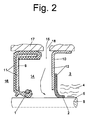
- Fig. 2 a second embodiment is shown, which differs from the previously described embodiment according to Fig. 1 differs in that the preassemblable units 11, 12 are arranged separately from each other and with an axial distance adjacent to each other in the installation space 14.
- an opening 18 is provided in the region of the axial distance between the units 11, 12 through which fresh oil can be fed into the installation space 14.
- the fresh oil may be clean or, for example, cleaned by an oil filter.
- the fresh oil then passes through the opening 18 into the installation space 14 and from there between the surface 5 to be sealed and the filter ring 2 into the space 3 to be sealed.
- a third embodiment is shown, similar to the embodiment of Fig. 1 , wherein the support body 9 of the sealing ring 1 is coated with an elastomer layer 19, which also forms the static seal 20 relative to the housing 17.
- an elastomer layer 19 On the space to be sealed 3 axially facing side of the elastomer layer 19, a recess 21 is provided, in which the filter ring 2 is disposed of filter fabric; the filter ring 2 and the sealing ring 1 are glued together.
- the filter ring consisting of filter fleece 2 ensures that impurities that are in the sealed lubricant 4 within the space to be sealed 3, do not reach the sealing ring 1.
- the sealing ring 1 thus has only a very small Wear and resulting consistently good performance during a long service life.
Landscapes
- Engineering & Computer Science (AREA)
- General Engineering & Computer Science (AREA)
- Mechanical Engineering (AREA)
- General Details Of Gearings (AREA)
- Sealing Devices (AREA)
- Sealing With Elastic Sealing Lips (AREA)
- Filtering Of Dispersed Particles In Gases (AREA)
- Lubrication Details And Ventilation Of Internal Combustion Engines (AREA)
Abstract
Description
- Die Erfindung betrifft eine Dichtungsanordnung und deren Verwendung, wobei die Dichtungsanordnung einen Dichtring umfasst und einen Filterring aus Filtervlies, der den Dichtring auf der einem abzudichtenden Raum zugewandten Seite mit axialem Abstand benachbart zugeordnet ist.
- Eine solche Dichtungsanordnung ist aus der
DE 36 19 309 C1 bekannt. Die Dichtungsanordnung umfasst eine Kühlwasserpumpendichtung für einen Verbrennungsmotor, bei dem der gleitend an der Welle anliegenden Hauptdichtung kühlwasserseitig eine Schutzdichtung vorgeschaltet ist, die aus einem Filtervlies besteht, wobei das Filtervlies an dem der Hauptdichtung tragenden Gehäuse befestigt ist. Das Filtervlies weist ein Flächengewicht von 60 bis 900g/m2 und eine Dicke von 1 mm bis 4 mm auf und besteht bevorzugt aus Polyesterfasern. - Der Erfindung liegt die Aufgabe zugrunde, eine Dichtungsanordnung für andere abzudichtenden Medien als Kühlwasser zu entwickeln.
- Diese Aufgabe wird durch eine Dichtungsanordnung gemäß Anspruch 1 gelöst. Auf vorteilhafte Ausgestaltungen nehmen die Unteransprüche Bezug.
- Außerdem soll die Dichtungsanordnung abweichend verwendet werden. Diese Aufgabe wird durch eine Verwendung gemäß Anspruch 10 gelöst.
- Zur Lösung der Aufgabe ist eine Dichtungsanordnung vorgesehen, umfassend einen Dichtring und einen Filterring aus Filtervlies, der dem Dichtring auf der einem abzudichtenden Raum zugewandten Seite mit axialem Abstand benachbart zugeordnet ist, wobei der abzudichtende Raum zumindest teilweise mit einem Schmiermittel gefüllt ist.
Üblicherweise werden Dichtringe, die ein Schmiermittel abdichten, durch das abzudichtende Schmiermittel geschmiert, so dass sie während einer möglichst langen Gebrauchsdauer möglichst gleichbleibend gute
Gebrauchseigenschaften aufweisen; der Verschleiß des Dichtringes soll durch die Schmierung auf ein Minimum reduziert werden.
Das setzt jedoch voraus, dass das abzudichtende Schmiermittel nach Möglichkeit keine Verunreinigungen, insbesondere keine abrasiv wirksamen Verunreinigungen, aufweist, die den Dichtring beschädigen könnten. Speziell bei der Verwendung von Dichtungsanordnungen in Getrieben oder Achsen von Kraftfahrzeugen ist eine Verunreinigung des abdichtenden Schmiermittels mit abrasiv wirksamen Partikeln jedoch nicht zu vermeiden, so dass der Dichtring der erfindungsgemäßen Dichtungsanordnung durch den in Richtung des abzudichtenden Raums axial vorgeschalteten Filterring aus Filtervlies vor einer Beaufschlagung mit diesen Verunreinigungen / Partikeln geschützt wird. Die Verunreinigungen werden durch den Filterring aus Filtervlies aufgenommen, und nur Schmiermittel, das frei von Verunreinigungen ist, gelangt durch den Filterring aus Filtervlies hindurch zu dem Dichtring, um diesen zu schmieren. Auch unter erschwerten Bedingungen, wie beispielsweise bei Verwendung der Dichtungsanordnung in einem Getriebe oder in einer Achse eines Kraftfahrzeugs, weist die Dichtungsanordnung gleichbleibend gute Gebrauchseigenschaften während einer langen Gebrauchsdauer auf, weil der Dichtring nur mit Schmiermittel beaufschlagt wird, aus dem die betriebsbedingt bei dieser Verwendung auftretenden Verunreinigungen herausgefiltert sind. - Der Dichtring und der Filterring können die abzudichtende Fläche eines abzudichtenden Maschinenelements anliegend umschließen. Der Dichtring umschließt die abzudichtende Fläche unter elastischer Vorspannung. Es kann vorgesehen sein, dass der Dichtring und der Filterring, jeweils bezogen auf die abzudichtende Fläche, jeweils eine Überdeckung aufweisen. Für manche Anwendungsfälle kann es sinnvoll sein, wenn der Filterring keine Überdeckung aufweist.
- Der Dichtring kann zum Beispiel als Radialwellendichtring ausgebildet sein und eine dynamisch beanspruchte Dichtlippe aufweisen, die axial in Richtung des abzudichtenden Raums vorgewölbt ist. Je nach Anwendungsfall kann die Dichtlippe durch eine Ringwendelfeder, die die Dichtlippe radial außenumfangsseitig umschließt, an die abzudichtende Fläche dichtend angedrückt werden. Generell besteht jedoch auch die Möglichkeit, dass die Dichtlippe die abzudichtende Fläche ohne Hilfsmittel, wie zum Beispiel die Ringwendelfeder, unter werkstoffbedingter elastischer Vorspannung dichtend umschließt.
- Der Filterring aus Filtervlies ist bevorzugt entsprechend dem Dichtring ebenfalls axial in Richtung des abzudichtenden Raums vorgewölbt, wobei die Überdeckung des Filterrings nur so gering ist, um eine umfangsseitige Berührung der abzudichtenden Fläche sicher zu stellen. Durch die geringe Überdeckung des Filterrings ist auch die Reibleistung sehr gering und dadurch auch die unerwünschte Entstehung von Wärme.
- Der Dichtring und der Filterring können jeweils an einem Stützkörper festgelegt sein und mit den zugehörigen Stützkörpern jeweils eine vormontierbare Einheit bilden. Hierbei ist von Vorteil, dass durch diese Modulbauweise unterschiedliche Dichtringe mit unterschiedlichen Filterringen kombinierbar sind. Die Stützkörper der jeweiligen Ringe bestehen bevorzugt aus einem zähharten Werkstoff, beispielsweise aus Blech oder einem polymeren Werkstoff. Die Gebrauchseigenschaften des Dichtrings und die Gebrauchseigenschaften des Filterrings können an den jeweiligen Anwendungsfall angepasst werden. Ist die Partikellast innerhalb des abzudichtenden Schmiermittels beispielsweise besonders groß und/oder der Werkstoff, aus dem der Dichtring besteht, besonders verschleißanfällig, kann ein Filterring aus einem Filtervlies vorgesehen sein, der eine besonders gute Filterwirkung aufweist. Soll demgegenüber der Dichtring besonders gut geschmiert werden und/oder das abzudichtende Schmiermittel weist eine nur sehr geringe Partikellast auf, kann das Filtervlies eine deutlich geringere Filterwirkung aufweisen und dadurch eine höhere Durchlässigkeit des abzudichtenden Schmiermittels zum Dichtring.
- Der Filterring und der Stützkörper können miteinander verklebt und/oder verklemmt sein.
- Nach einer anderen Ausgestaltung können der Filterring und der Dichtring miteinander verklebt sein.
- Nach einer ersten Ausgestaltung kann es vorgesehen sein, dass die beiden vormontierbaren Einheiten miteinander verbunden sind und eine weitere Einheit bilden. Die weitere Einheit ist einfach zu handhaben, weil sie den Dichtring und den Filterring umfasst. Die Gefahr von Montagefehlem ist dadurch auf ein Minimum begrenzt.
- Nach einer anderen Ausgestaltung kann es vorgesehen sein, dass die vormontierbaren Einheiten mit axialem Abstand zueinander benachbart im Einbauraum angeordnet sind. Hierbei ist von Vorteil, dass in den Einbauraum axial zwischen den vormontierbaren Einheiten eine Zuleitung für Frischöl angeordnet sein kann. Das Frischöl wird nach seiner Einleitung in die Dichtungsanordnung in Richtung des abzudichtenden Raums, am vorgewölbten Filterring vorbei in den abzudichtenden Raum gefördert. Der Filterring fungiert dann als eine Art Rückschlagventil. Nachdem das Frischöl in den abzudichtenden Raum gelangt ist, legt sich der Filterring wieder an die abzudichtende Fläche an, um einen direkten und ungefilterten Durchtritt von verunreinigtem Schmiermittel aus dem abzudichtenden Raum zurück an den Dichtring zu verhindern.
- Das Filtervlies des Filterrings ist bevorzugt laminiert. Dadurch wird eine bessere Bindung des Filtervlieses erreicht, und der Ausriss von Fasern während der bestimmungsgemäßen Verwendung der Dichtungsanordnung wird minimiert. Das ist insofern wichtig, als ein Ausriss von Fasern den Dichtmechanismus des Dichtrings gefährden könnte, weil zum Beispiel eine Rückfördereinrichtung des Dichtrings, die gegebenenfalls vorgesehen sein kann, um abzudichtendes Medium in Richtung des abzudichtenden Raums zurückzufördem, durch ausgerissene Fasern außer Funktion gesetzt werden kann.
- Eine besonders gute Bindung des Filtervlieses wird bevorzugt durch eine NBR-Laminierung erreicht.
- Das Schmiermittel kann durch ein Schmieröl gebildet sein.
- Die zuvor beschriebene Dichtungsanordnung kann in Getrieben oder Achsen von Nutzfahrzeugen Verwendung finden, insbesondere in Getrieben oder Achsen von schnellen Kleintransportern. Durch die im Vergleich zu Personenkraftwagen deutlich größeren Abmessungen der Dichtungsanordnung bei ungefähr gleichen Drehzahlen, werden an Dichtungsanordnungen für derartige Verwendungen besonders hohe Anforderungen an die Funktion und die Haltbarkeit gestellt. Das Schmieröl ist häufig stärker verunreinigt. Der Dichtring wird durch den in Richtung des abzudichtenden Raums vorgeschalteten Filterring besonders zuverlässig geschützt.
- Die Dichtungsanordnung kann auch im stationären Getrieben zur Anwendung gelangen.
- Drei Ausführungsbeispiele der erfindungsgemäßen Dichtungsanordnung werden nachfolgend näher beschrieben.
- Diese zeigen jeweils in schematischer Darstellung:
- Fig. 1
- ein erstes Ausführungsbeispiel, bei dem der Dichtring und der Filterring die weitere Einheit bilden,
- Fig. 2
- ein zweites Ausführungsbeispiel, das sich vom Ausführungsbeispiel aus
Fig. 1 dadurch unterscheidet, dass die beiden vormontierbaren Einheiten innerhalb des Einbauraums getrennt verbaut sind, - Fig. 3
- ein drittes Ausführungsbeispiel, bei dem der Filterring an einem elastomeren Werkstoffüberzug des Stützrings des Dichtrings festgelegt ist.
- In den
Fig. 1 bis 3 ist jeweils eine Dichtungsanordnung gezeigt, die einen Dichtring 1 und einen Filterring 2 umfasst, wobei der Filterring 2 aus einem Filtervlies besteht. Der Filterring 2 ist dem Dichtring 1 auf der dem abzudichtenden Raum 3 zugewandten Seite mit axialem Abstand benachbart zugeordnet, wobei der abzudichtende Raum 3 in den hier gezeigten Ausführungsbeispielen in einem Getriebe oder in einer Achse eines Kraftfahrzeugs angeordnet ist. Innerhalb des abzudichtenden Raums 3 ist ein Schmiermittel 4, beispielsweise ein Schmieröl, angeordnet, das gegenüber der Umgebung 16 abgedichtet wird. Das abzudichtende Maschinenelement 6 ist in den hier gezeigten Ausführungsbeispielen eine Achse oder eine Welle, wobei sowohl der Dichtring 1 als auch der Filterring 2 die abzudichtende Fläche 5 des abzudichtenden Maschinenelements 6 anliegend umschließen.
Bezogen auf die abzudichtende Fläche 5 weisen sowohl der Dichtring 1 als auch der Filterring 2 jeweils eine Überdeckung 7, 8 auf, wobei die Überdeckung 8 des Filterrings 2 nur sehr gering ist, bevorzugt ≤ 1 mm, bezogen auf die abzudichtende Fläche 5. Durch diese geringe Überdeckung 8 wird sicher gestellt, dass der Filterring 2 die abzudichtende Fläche 5, in Umfangsrichtung betrachtet, einerseits durchgängig berührt, ohne dass es andererseits zu einer unerwünscht großen Wärmeentwicklung durch Reibung kommt. - In
Fig. 1 ist ein erstes Ausführungsbeispiel der erfindungsgemäßen Dichtungsanordnung gezeigt. Der Dichtring 1 ist mit dem Stützkörper 9, der Filterring 2 mit dem Stützkörper 10 verbunden, wobei die beiden Stützkörper 9, 10 jeweils aus einem Blech bestehen. Die vormontierbare Einheit 11 wird durch den Dichtring 1 und den entsprechenden Stützkörper 9, die vormontierbare Einheit 12 durch den Filterring 2 und den entsprechenden Stützkörper 10 gebildet, wobei diese vormontierbaren Einheiten 11, 12 inFig. 1 zu der weiteren Einheit 13 zusammengefasst sind. Der axiale Abstand zwischen dem Dichtring 1 und dem Filterring 2 ist dadurch vorgegeben und stets konstant. - In
Fig. 2 ist ein zweites Ausführungsbeispiel gezeigt, das sich vom zuvor beschriebenen Ausführungsbeispiel gemäßFig. 1 dadurch unterscheidet, dass die vormontierbaren Einheiten 11, 12 getrennt voneinander und mit axialem Abstand zueinander benachbart im Einbauraum 14 angeordnet sind. Innerhalb des Gehäuses 17 ist im Bereich des axialen Abstands zwischen den Einheiten 11, 12 eine Durchbrechung 18 vorgesehen, durch die Frischöl in den Einbauraum 14 eingespeist werden kann. Das Frischöl kann sauber oder zum Beispiel durch einen Ölfilter gereinigt worden sein. Das Frischöl gelangt dann durch die Durchbrechung 18 hindurch in den Einbauraum 14 und von dort zwischen der abzudichtenden Fläche 5 und dem Filterring 2 hindurch in den abzudichtenden Raum 3. - In
Fig. 3 ist ein drittes Ausführungsbeispiel gezeigt, ähnlich dem Ausführungsbeispiel ausFig. 1 , wobei der Stützkörper 9 des Dichtrings 1 mit einer Elastomerschicht 19 überzogen ist, die auch die statische Dichtung 20 gegenüber dem Gehäuse 17 bildet. Auf der dem abzudichtenden Raum 3 axial zugewandten Seite der Elastomerschicht 19 ist eine Ausnehmung 21 vorgesehen, in der der Filterring 2 aus Filtervlies angeordnet ist; der Filterring 2 und der Dichtring 1 sind miteinander verklebt. - In allen drei Ausführungsbeispielen sorgt der aus Filtervlies bestehende Filterring 2 dafür, dass Verunreinigungen, die sich im abzudichtenden Schmiermittel 4 innerhalb des abzudichtenden Raums 3 befinden, nicht zum Dichtring 1 gelangen. Der Dichtring 1 weist dadurch nur einen sehr geringen Verschleiß und daraus resultierend gleichbleibend gute Gebrauchseigenschaften während einer langen Gebrauchsdauer auf.
Claims (12)
- Dichtungsanordnung, umfassend einen Dichtring (1) und einen Filterring (2) aus Filtervlies, der dem Dichtring (1) auf der einem abzudichtenden Raum (3) zugewandten Seite mit axialem Abstand benachbart zugeordnet ist, wobei der abzudichtende Raum (3) zumindest teilweise mit einem Schmiermittel (4) gefüllt ist.
- Dichtungsanordnung nach Anspruch 1, dadurch gekennzeichnet, dass der Dichtring (1) und der Filterring (2) die abzudichtenden Fläche (5) eines abzudichtenden Maschinenelements (6) anliegend umschließen.
- Dichtungsanordnung nach einem der Ansprüche 1 oder 2, dadurch gekennzeichnet, dass der Dichtring (1) und der Filterring (2), jeweils bezogen auf die abzudichtende Fläche (5), jeweils eine Überdeckung (7, 8) aufweisen.
- Dichtungsanordnung nach einem der Ansprüche 1 bis 3, dadurch gekennzeichnet, dass der Dichtring (1) und der Filterring (2) jeweils an einem Stützkörper (9, 10) festgelegt sind und mit den zugehörigen Stützkörpern (9, 10) jeweils eine vormontierbare Einheit (11, 12) bilden.
- Dichtungsanordnung nach Anspruch 4, dadurch gekennzeichnet, dass der Filterring (2) und der Stützkörper (10) miteinander verklebt und/oder verklemmt sind.
- Dichtungsanordnung nach Anspruch 4, dadurch gekennzeichnet, dass der Filterring (2) und der Dichtring (1) miteinander verklebt sind.
- Dichtungsanordnung nach einem der Ansprüche 4 bis 6, dadurch gekennzeichnet, dass die vormontierbaren Einheiten (11, 12) miteinander verbunden sind und eine weitere Einheit (13) bilden.
- Dichtungsanordnung nach einem der Ansprüche 4 bis 6, dadurch gekennzeichnet, dass die vormontierbaren Einheiten (11, 12) mit axialem Abstand zueinander benachbart im Einbauraum (14) angeordnet sind.
- Dichtungsanordnung nach Anspruch 8, dadurch gekennzeichnet, dass in dem Einbauraum (14) axial zwischen den vormontierbaren Einheiten (11, 12) eine Zuleitung (15) für Frischöl angeordnet ist.
- Dichtungsanordnung nach einem der Ansprüche 1 bis 9, dadurch gekennzeichnet, dass das Filtervlies des Filterrings (2) laminiert ist.
- Dichtungsanordnung nach einem der Ansprüche 1 bis 10, dadurch gekennzeichnet, dass das Schmiermittel (4) durch ein Schmieröl gebildet ist.
- Verwendung einer Dichtungsanordnung nach einem der Ansprüche 1 bis 10 in einem Getriebe oder in einer Achse eines Nutzfahrzeugs.
Priority Applications (4)
| Application Number | Priority Date | Filing Date | Title |
|---|---|---|---|
| EP09011034.7A EP2290271B1 (de) | 2009-08-28 | 2009-08-28 | Dichtungsanordnung und deren Verwendung |
| BRPI1003071A BRPI1003071B1 (pt) | 2009-08-28 | 2010-08-27 | disposição de vedação e seu uso |
| RU2010136205/06A RU2454581C2 (ru) | 2009-08-28 | 2010-08-27 | Уплотнительное устройство и его применение |
| CN2010102688499A CN102003535A (zh) | 2009-08-28 | 2010-08-27 | 密封装置及其应用 |
Applications Claiming Priority (1)
| Application Number | Priority Date | Filing Date | Title |
|---|---|---|---|
| EP09011034.7A EP2290271B1 (de) | 2009-08-28 | 2009-08-28 | Dichtungsanordnung und deren Verwendung |
Publications (2)
| Publication Number | Publication Date |
|---|---|
| EP2290271A1 true EP2290271A1 (de) | 2011-03-02 |
| EP2290271B1 EP2290271B1 (de) | 2019-04-03 |
Family
ID=41558183
Family Applications (1)
| Application Number | Title | Priority Date | Filing Date |
|---|---|---|---|
| EP09011034.7A Not-in-force EP2290271B1 (de) | 2009-08-28 | 2009-08-28 | Dichtungsanordnung und deren Verwendung |
Country Status (4)
| Country | Link |
|---|---|
| EP (1) | EP2290271B1 (de) |
| CN (1) | CN102003535A (de) |
| BR (1) | BRPI1003071B1 (de) |
| RU (1) | RU2454581C2 (de) |
Cited By (4)
| Publication number | Priority date | Publication date | Assignee | Title |
|---|---|---|---|---|
| DE102012008387A1 (de) | 2012-04-04 | 2013-10-10 | Carl Freudenberg Kg | Dichtungsanordnung |
| DE102021206769A1 (de) | 2021-06-29 | 2022-12-29 | Trelleborg Sealing Solutions Germany Gmbh | Rotationsdichtungsanordnung mit Rotationsdichtung und mit ölseitig angeordnetem Schaumring |
| US11846354B2 (en) | 2019-09-04 | 2023-12-19 | Nok Corporation | Sealing device |
| DE102023130792A1 (de) * | 2023-11-07 | 2025-05-08 | Carl Freudenberg Kg | Dichtungsanordnung mit Erdungselement |
Families Citing this family (1)
| Publication number | Priority date | Publication date | Assignee | Title |
|---|---|---|---|---|
| DE102017116093A1 (de) | 2017-07-18 | 2019-01-24 | Dätwyler Sealing Technologies Deutschland Gmbh | Dichtungsprofil zur Einbettung in ein Formteil aus aushärtbarem Material |
Citations (12)
| Publication number | Priority date | Publication date | Assignee | Title |
|---|---|---|---|---|
| GB534408A (en) | 1939-01-06 | 1941-03-06 | American Felt Co | Improvements in or relating to fluid seals |
| DE867189C (de) | 1951-05-24 | 1953-02-16 | Kupfer Asbest Co | In ein Gehaeuse eingebaute Wellendichtung mit Staubdichtung |
| DE7328356U (de) | 1973-11-29 | Freudenberg C | Dichtring mit Staubschutz, insbe sondere zur Wellenabdichtung | |
| GB1453122A (en) * | 1973-01-05 | 1976-10-20 | Itt | Sealing arrangement including a filter for use with a rotatable hsaft |
| DE2825622A1 (de) * | 1978-06-12 | 1980-01-03 | Lechler Elring Dichtungswerke | Anordnung zur abdichtung von rotierenden wellen, insbesondere kurbelwellen in hubkolbenmotoren |
| DE3619309C1 (de) | 1986-06-07 | 1987-09-17 | Freudenberg Carl Fa | Kuehlwasserpumpendichtung |
| US5110143A (en) | 1990-11-30 | 1992-05-05 | Fmc Corporation | Seal cartridge for use in idler rollers |
| US5704719A (en) | 1996-07-01 | 1998-01-06 | Emerson Power Transmission Corp. | Street sweeper bearing with wear resistant resiliently biased face seal |
| US5996542A (en) | 1997-06-21 | 1999-12-07 | Perkins Engines Company Limited | Rotary shaft sealing system |
| EP1026428A2 (de) | 1999-02-06 | 2000-08-09 | Firma Carl Freudenberg | Dichtring |
| WO2003031851A1 (de) | 2001-10-02 | 2003-04-17 | Carl Freudenberg Kg | Radialwellendichtung und verfahren zu ihrer herstellung |
| JP2007046653A (ja) | 2005-08-08 | 2007-02-22 | Tsubaki Emerson Co | 歯車減速機の軸封部構造 |
Family Cites Families (3)
| Publication number | Priority date | Publication date | Assignee | Title |
|---|---|---|---|---|
| US4155560A (en) * | 1977-11-23 | 1979-05-22 | Garlock Inc. | Water pump seal and method |
| US5271629A (en) * | 1990-04-14 | 1993-12-21 | Firma Carl Freudenberg | Radial shaft sealing ring |
| RU2187728C2 (ru) * | 2000-08-10 | 2002-08-20 | Российский Федеральный Ядерный Центр - Всероссийский Научно-Исследовательский Институт Экспериментальной Физики | Уплотнение штока для высокого давления |
-
2009
- 2009-08-28 EP EP09011034.7A patent/EP2290271B1/de not_active Not-in-force
-
2010
- 2010-08-27 RU RU2010136205/06A patent/RU2454581C2/ru active
- 2010-08-27 CN CN2010102688499A patent/CN102003535A/zh active Pending
- 2010-08-27 BR BRPI1003071A patent/BRPI1003071B1/pt not_active IP Right Cessation
Patent Citations (12)
| Publication number | Priority date | Publication date | Assignee | Title |
|---|---|---|---|---|
| DE7328356U (de) | 1973-11-29 | Freudenberg C | Dichtring mit Staubschutz, insbe sondere zur Wellenabdichtung | |
| GB534408A (en) | 1939-01-06 | 1941-03-06 | American Felt Co | Improvements in or relating to fluid seals |
| DE867189C (de) | 1951-05-24 | 1953-02-16 | Kupfer Asbest Co | In ein Gehaeuse eingebaute Wellendichtung mit Staubdichtung |
| GB1453122A (en) * | 1973-01-05 | 1976-10-20 | Itt | Sealing arrangement including a filter for use with a rotatable hsaft |
| DE2825622A1 (de) * | 1978-06-12 | 1980-01-03 | Lechler Elring Dichtungswerke | Anordnung zur abdichtung von rotierenden wellen, insbesondere kurbelwellen in hubkolbenmotoren |
| DE3619309C1 (de) | 1986-06-07 | 1987-09-17 | Freudenberg Carl Fa | Kuehlwasserpumpendichtung |
| US5110143A (en) | 1990-11-30 | 1992-05-05 | Fmc Corporation | Seal cartridge for use in idler rollers |
| US5704719A (en) | 1996-07-01 | 1998-01-06 | Emerson Power Transmission Corp. | Street sweeper bearing with wear resistant resiliently biased face seal |
| US5996542A (en) | 1997-06-21 | 1999-12-07 | Perkins Engines Company Limited | Rotary shaft sealing system |
| EP1026428A2 (de) | 1999-02-06 | 2000-08-09 | Firma Carl Freudenberg | Dichtring |
| WO2003031851A1 (de) | 2001-10-02 | 2003-04-17 | Carl Freudenberg Kg | Radialwellendichtung und verfahren zu ihrer herstellung |
| JP2007046653A (ja) | 2005-08-08 | 2007-02-22 | Tsubaki Emerson Co | 歯車減速機の軸封部構造 |
Cited By (6)
| Publication number | Priority date | Publication date | Assignee | Title |
|---|---|---|---|---|
| DE102012008387A1 (de) | 2012-04-04 | 2013-10-10 | Carl Freudenberg Kg | Dichtungsanordnung |
| EP2647889A3 (de) * | 2012-04-04 | 2014-06-04 | Carl Freudenberg KG | Dichtungsanordnung |
| US11846354B2 (en) | 2019-09-04 | 2023-12-19 | Nok Corporation | Sealing device |
| DE102021206769A1 (de) | 2021-06-29 | 2022-12-29 | Trelleborg Sealing Solutions Germany Gmbh | Rotationsdichtungsanordnung mit Rotationsdichtung und mit ölseitig angeordnetem Schaumring |
| DE102021206769B4 (de) * | 2021-06-29 | 2025-05-22 | Trelleborg Sealing Solutions Germany Gmbh | Rotationsdichtungsanordnung mit Rotationsdichtung und mit ölseitig angeordnetem Schaumring |
| DE102023130792A1 (de) * | 2023-11-07 | 2025-05-08 | Carl Freudenberg Kg | Dichtungsanordnung mit Erdungselement |
Also Published As
| Publication number | Publication date |
|---|---|
| EP2290271B1 (de) | 2019-04-03 |
| CN102003535A (zh) | 2011-04-06 |
| RU2454581C2 (ru) | 2012-06-27 |
| BRPI1003071B1 (pt) | 2020-01-21 |
| RU2010136205A (ru) | 2012-03-10 |
| BRPI1003071A2 (pt) | 2012-04-24 |
Similar Documents
| Publication | Publication Date | Title |
|---|---|---|
| EP2290271B1 (de) | Dichtungsanordnung und deren Verwendung | |
| DE102008028115A1 (de) | Lager | |
| EP2195563A1 (de) | Dichtungsanordnung für ein lager | |
| DE102012013924A1 (de) | Wellfeder mit bereichsweise linearer Kennlinie | |
| EP2290270A1 (de) | Dichtungsanordnung und deren Verwendung | |
| DE2850891A1 (de) | Dichtung | |
| DE19846153C1 (de) | Gleitringdichtung | |
| DE102004031559A1 (de) | Elastomeres Buchsenlager mit verbessertem Torsionsverhalten | |
| EP1526310A1 (de) | Dichtungsanordnung | |
| DE102019204877A1 (de) | Dichtungsstruktur und diese Dichtungsstruktur aufweisende Vorrichtung | |
| DE19914929C2 (de) | Gleitringdichtung | |
| DE102008063597A1 (de) | Dichtungsanordnung mit Dichtlippenschutz | |
| EP2647889A2 (de) | Dichtungsanordnung | |
| EP2466172B1 (de) | Dichtring | |
| WO2015018383A1 (de) | Ausrücklageranordnung | |
| DE102009005775B4 (de) | Lagerabdichtungsanordnung | |
| EP2861897B2 (de) | Gleitringdichtung | |
| EP3542885A2 (de) | Filterelement mit filtermaterial und herstellungsverfahren | |
| EP4001708B1 (de) | Dichtring und dessen verwendung | |
| DE102006011620B3 (de) | Gleitringdichtung | |
| DE102018119124A1 (de) | Getriebe | |
| DE10140730A1 (de) | Abstreifer | |
| DE102017004480A1 (de) | Dichtring und Dichtungsanordnung, die den Dichtring umfasst | |
| DE102019113615A1 (de) | Brennkraftmaschine mit einer Umlaufschmierung | |
| DE102012211631A1 (de) | Drosselvorrichtung mit zusätzlichen Wellenlagerabdichtungen |
Legal Events
| Date | Code | Title | Description |
|---|---|---|---|
| PUAI | Public reference made under article 153(3) epc to a published international application that has entered the european phase |
Free format text: ORIGINAL CODE: 0009012 |
|
| 17P | Request for examination filed |
Effective date: 20100308 |
|
| AK | Designated contracting states |
Kind code of ref document: A1 Designated state(s): AT BE BG CH CY CZ DE DK EE ES FI FR GB GR HR HU IE IS IT LI LT LU LV MC MK MT NL NO PL PT RO SE SI SK SM TR |
|
| AX | Request for extension of the european patent |
Extension state: AL BA RS |
|
| RIN1 | Information on inventor provided before grant (corrected) |
Inventor name: HOFMANN, JENS Inventor name: BEGLE, STEPHAN |
|
| RIN1 | Information on inventor provided before grant (corrected) |
Inventor name: BEGLE, STEPHAN Inventor name: HOFMANN, JENS |
|
| STAA | Information on the status of an ep patent application or granted ep patent |
Free format text: STATUS: EXAMINATION IS IN PROGRESS |
|
| 17Q | First examination report despatched |
Effective date: 20170118 |
|
| RIN1 | Information on inventor provided before grant (corrected) |
Inventor name: BEGLE, STEPHAN Inventor name: HOFMANN, JENS |
|
| REG | Reference to a national code |
Ref country code: DE Ref legal event code: R079 Ref document number: 502009015682 Country of ref document: DE Free format text: PREVIOUS MAIN CLASS: F16J0015320000 Ipc: F16J0015325200 |
|
| RIC1 | Information provided on ipc code assigned before grant |
Ipc: F16J 15/00 20060101ALI20181018BHEP Ipc: F16J 15/3252 20110302AFI20181018BHEP |
|
| GRAP | Despatch of communication of intention to grant a patent |
Free format text: ORIGINAL CODE: EPIDOSNIGR1 |
|
| STAA | Information on the status of an ep patent application or granted ep patent |
Free format text: STATUS: GRANT OF PATENT IS INTENDED |
|
| INTG | Intention to grant announced |
Effective date: 20181130 |
|
| RIC1 | Information provided on ipc code assigned before grant |
Ipc: F16J 15/3252 20160101AFI20181018BHEP Ipc: F16J 15/00 20060101ALI20181018BHEP |
|
| RIC1 | Information provided on ipc code assigned before grant |
Ipc: F16J 15/3252 20160101AFI20181018BHEP Ipc: F16J 15/00 20060101ALI20181018BHEP |
|
| GRAS | Grant fee paid |
Free format text: ORIGINAL CODE: EPIDOSNIGR3 |
|
| GRAA | (expected) grant |
Free format text: ORIGINAL CODE: 0009210 |
|
| STAA | Information on the status of an ep patent application or granted ep patent |
Free format text: STATUS: THE PATENT HAS BEEN GRANTED |
|
| AK | Designated contracting states |
Kind code of ref document: B1 Designated state(s): AT BE BG CH CY CZ DE DK EE ES FI FR GB GR HR HU IE IS IT LI LT LU LV MC MK MT NL NO PL PT RO SE SI SK SM TR |
|
| REG | Reference to a national code |
Ref country code: GB Ref legal event code: FG4D Free format text: NOT ENGLISH |
|
| RIN1 | Information on inventor provided before grant (corrected) |
Inventor name: BEGLE, STEPHAN Inventor name: HOFMANN, JENS |
|
| REG | Reference to a national code |
Ref country code: CH Ref legal event code: EP Ref country code: AT Ref legal event code: REF Ref document number: 1116126 Country of ref document: AT Kind code of ref document: T Effective date: 20190415 |
|
| REG | Reference to a national code |
Ref country code: DE Ref legal event code: R096 Ref document number: 502009015682 Country of ref document: DE |
|
| REG | Reference to a national code |
Ref country code: IE Ref legal event code: FG4D Free format text: LANGUAGE OF EP DOCUMENT: GERMAN |
|
| REG | Reference to a national code |
Ref country code: NL Ref legal event code: MP Effective date: 20190403 |
|
| REG | Reference to a national code |
Ref country code: LT Ref legal event code: MG4D |
|
| PG25 | Lapsed in a contracting state [announced via postgrant information from national office to epo] |
Ref country code: NL Free format text: LAPSE BECAUSE OF FAILURE TO SUBMIT A TRANSLATION OF THE DESCRIPTION OR TO PAY THE FEE WITHIN THE PRESCRIBED TIME-LIMIT Effective date: 20190403 |
|
| PG25 | Lapsed in a contracting state [announced via postgrant information from national office to epo] |
Ref country code: CZ Free format text: LAPSE BECAUSE OF FAILURE TO SUBMIT A TRANSLATION OF THE DESCRIPTION OR TO PAY THE FEE WITHIN THE PRESCRIBED TIME-LIMIT Effective date: 20190403 Ref country code: NO Free format text: LAPSE BECAUSE OF FAILURE TO SUBMIT A TRANSLATION OF THE DESCRIPTION OR TO PAY THE FEE WITHIN THE PRESCRIBED TIME-LIMIT Effective date: 20190703 Ref country code: LT Free format text: LAPSE BECAUSE OF FAILURE TO SUBMIT A TRANSLATION OF THE DESCRIPTION OR TO PAY THE FEE WITHIN THE PRESCRIBED TIME-LIMIT Effective date: 20190403 Ref country code: ES Free format text: LAPSE BECAUSE OF FAILURE TO SUBMIT A TRANSLATION OF THE DESCRIPTION OR TO PAY THE FEE WITHIN THE PRESCRIBED TIME-LIMIT Effective date: 20190403 Ref country code: SE Free format text: LAPSE BECAUSE OF FAILURE TO SUBMIT A TRANSLATION OF THE DESCRIPTION OR TO PAY THE FEE WITHIN THE PRESCRIBED TIME-LIMIT Effective date: 20190403 Ref country code: HR Free format text: LAPSE BECAUSE OF FAILURE TO SUBMIT A TRANSLATION OF THE DESCRIPTION OR TO PAY THE FEE WITHIN THE PRESCRIBED TIME-LIMIT Effective date: 20190403 Ref country code: PT Free format text: LAPSE BECAUSE OF FAILURE TO SUBMIT A TRANSLATION OF THE DESCRIPTION OR TO PAY THE FEE WITHIN THE PRESCRIBED TIME-LIMIT Effective date: 20190803 Ref country code: FI Free format text: LAPSE BECAUSE OF FAILURE TO SUBMIT A TRANSLATION OF THE DESCRIPTION OR TO PAY THE FEE WITHIN THE PRESCRIBED TIME-LIMIT Effective date: 20190403 |
|
| PG25 | Lapsed in a contracting state [announced via postgrant information from national office to epo] |
Ref country code: LV Free format text: LAPSE BECAUSE OF FAILURE TO SUBMIT A TRANSLATION OF THE DESCRIPTION OR TO PAY THE FEE WITHIN THE PRESCRIBED TIME-LIMIT Effective date: 20190403 Ref country code: GR Free format text: LAPSE BECAUSE OF FAILURE TO SUBMIT A TRANSLATION OF THE DESCRIPTION OR TO PAY THE FEE WITHIN THE PRESCRIBED TIME-LIMIT Effective date: 20190704 Ref country code: PL Free format text: LAPSE BECAUSE OF FAILURE TO SUBMIT A TRANSLATION OF THE DESCRIPTION OR TO PAY THE FEE WITHIN THE PRESCRIBED TIME-LIMIT Effective date: 20190403 Ref country code: BG Free format text: LAPSE BECAUSE OF FAILURE TO SUBMIT A TRANSLATION OF THE DESCRIPTION OR TO PAY THE FEE WITHIN THE PRESCRIBED TIME-LIMIT Effective date: 20190703 |
|
| PG25 | Lapsed in a contracting state [announced via postgrant information from national office to epo] |
Ref country code: IS Free format text: LAPSE BECAUSE OF FAILURE TO SUBMIT A TRANSLATION OF THE DESCRIPTION OR TO PAY THE FEE WITHIN THE PRESCRIBED TIME-LIMIT Effective date: 20190803 |
|
| REG | Reference to a national code |
Ref country code: DE Ref legal event code: R097 Ref document number: 502009015682 Country of ref document: DE |
|
| PG25 | Lapsed in a contracting state [announced via postgrant information from national office to epo] |
Ref country code: RO Free format text: LAPSE BECAUSE OF FAILURE TO SUBMIT A TRANSLATION OF THE DESCRIPTION OR TO PAY THE FEE WITHIN THE PRESCRIBED TIME-LIMIT Effective date: 20190403 Ref country code: SK Free format text: LAPSE BECAUSE OF FAILURE TO SUBMIT A TRANSLATION OF THE DESCRIPTION OR TO PAY THE FEE WITHIN THE PRESCRIBED TIME-LIMIT Effective date: 20190403 Ref country code: DK Free format text: LAPSE BECAUSE OF FAILURE TO SUBMIT A TRANSLATION OF THE DESCRIPTION OR TO PAY THE FEE WITHIN THE PRESCRIBED TIME-LIMIT Effective date: 20190403 Ref country code: EE Free format text: LAPSE BECAUSE OF FAILURE TO SUBMIT A TRANSLATION OF THE DESCRIPTION OR TO PAY THE FEE WITHIN THE PRESCRIBED TIME-LIMIT Effective date: 20190403 |
|
| PLBE | No opposition filed within time limit |
Free format text: ORIGINAL CODE: 0009261 |
|
| STAA | Information on the status of an ep patent application or granted ep patent |
Free format text: STATUS: NO OPPOSITION FILED WITHIN TIME LIMIT |
|
| PG25 | Lapsed in a contracting state [announced via postgrant information from national office to epo] |
Ref country code: IT Free format text: LAPSE BECAUSE OF FAILURE TO SUBMIT A TRANSLATION OF THE DESCRIPTION OR TO PAY THE FEE WITHIN THE PRESCRIBED TIME-LIMIT Effective date: 20190403 Ref country code: SM Free format text: LAPSE BECAUSE OF FAILURE TO SUBMIT A TRANSLATION OF THE DESCRIPTION OR TO PAY THE FEE WITHIN THE PRESCRIBED TIME-LIMIT Effective date: 20190403 |
|
| 26N | No opposition filed |
Effective date: 20200106 |
|
| PG25 | Lapsed in a contracting state [announced via postgrant information from national office to epo] |
Ref country code: TR Free format text: LAPSE BECAUSE OF FAILURE TO SUBMIT A TRANSLATION OF THE DESCRIPTION OR TO PAY THE FEE WITHIN THE PRESCRIBED TIME-LIMIT Effective date: 20190403 |
|
| GBPC | Gb: european patent ceased through non-payment of renewal fee |
Effective date: 20190828 |
|
| PG25 | Lapsed in a contracting state [announced via postgrant information from national office to epo] |
Ref country code: SI Free format text: LAPSE BECAUSE OF FAILURE TO SUBMIT A TRANSLATION OF THE DESCRIPTION OR TO PAY THE FEE WITHIN THE PRESCRIBED TIME-LIMIT Effective date: 20190403 Ref country code: MC Free format text: LAPSE BECAUSE OF FAILURE TO SUBMIT A TRANSLATION OF THE DESCRIPTION OR TO PAY THE FEE WITHIN THE PRESCRIBED TIME-LIMIT Effective date: 20190403 Ref country code: LU Free format text: LAPSE BECAUSE OF NON-PAYMENT OF DUE FEES Effective date: 20190828 Ref country code: LI Free format text: LAPSE BECAUSE OF NON-PAYMENT OF DUE FEES Effective date: 20190831 Ref country code: CH Free format text: LAPSE BECAUSE OF NON-PAYMENT OF DUE FEES Effective date: 20190831 |
|
| REG | Reference to a national code |
Ref country code: BE Ref legal event code: MM Effective date: 20190831 |
|
| PG25 | Lapsed in a contracting state [announced via postgrant information from national office to epo] |
Ref country code: FR Free format text: LAPSE BECAUSE OF NON-PAYMENT OF DUE FEES Effective date: 20190831 Ref country code: IE Free format text: LAPSE BECAUSE OF NON-PAYMENT OF DUE FEES Effective date: 20190828 |
|
| PG25 | Lapsed in a contracting state [announced via postgrant information from national office to epo] |
Ref country code: BE Free format text: LAPSE BECAUSE OF NON-PAYMENT OF DUE FEES Effective date: 20190831 Ref country code: GB Free format text: LAPSE BECAUSE OF NON-PAYMENT OF DUE FEES Effective date: 20190828 |
|
| REG | Reference to a national code |
Ref country code: AT Ref legal event code: MM01 Ref document number: 1116126 Country of ref document: AT Kind code of ref document: T Effective date: 20190828 |
|
| PGFP | Annual fee paid to national office [announced via postgrant information from national office to epo] |
Ref country code: DE Payment date: 20200825 Year of fee payment: 12 |
|
| PG25 | Lapsed in a contracting state [announced via postgrant information from national office to epo] |
Ref country code: AT Free format text: LAPSE BECAUSE OF NON-PAYMENT OF DUE FEES Effective date: 20190828 |
|
| PG25 | Lapsed in a contracting state [announced via postgrant information from national office to epo] |
Ref country code: CY Free format text: LAPSE BECAUSE OF FAILURE TO SUBMIT A TRANSLATION OF THE DESCRIPTION OR TO PAY THE FEE WITHIN THE PRESCRIBED TIME-LIMIT Effective date: 20190403 |
|
| PG25 | Lapsed in a contracting state [announced via postgrant information from national office to epo] |
Ref country code: MT Free format text: LAPSE BECAUSE OF FAILURE TO SUBMIT A TRANSLATION OF THE DESCRIPTION OR TO PAY THE FEE WITHIN THE PRESCRIBED TIME-LIMIT Effective date: 20190403 Ref country code: HU Free format text: LAPSE BECAUSE OF FAILURE TO SUBMIT A TRANSLATION OF THE DESCRIPTION OR TO PAY THE FEE WITHIN THE PRESCRIBED TIME-LIMIT; INVALID AB INITIO Effective date: 20090828 |
|
| REG | Reference to a national code |
Ref country code: DE Ref legal event code: R119 Ref document number: 502009015682 Country of ref document: DE |
|
| PG25 | Lapsed in a contracting state [announced via postgrant information from national office to epo] |
Ref country code: MK Free format text: LAPSE BECAUSE OF FAILURE TO SUBMIT A TRANSLATION OF THE DESCRIPTION OR TO PAY THE FEE WITHIN THE PRESCRIBED TIME-LIMIT Effective date: 20190403 |
|
| PG25 | Lapsed in a contracting state [announced via postgrant information from national office to epo] |
Ref country code: DE Free format text: LAPSE BECAUSE OF NON-PAYMENT OF DUE FEES Effective date: 20220301 |