EP2290163A1 - Construction machine - Google Patents
Construction machine Download PDFInfo
- Publication number
- EP2290163A1 EP2290163A1 EP09754508A EP09754508A EP2290163A1 EP 2290163 A1 EP2290163 A1 EP 2290163A1 EP 09754508 A EP09754508 A EP 09754508A EP 09754508 A EP09754508 A EP 09754508A EP 2290163 A1 EP2290163 A1 EP 2290163A1
- Authority
- EP
- European Patent Office
- Prior art keywords
- boom
- cylinder
- end side
- proximal end
- positioning cylinder
- Prior art date
- Legal status (The legal status is an assumption and is not a legal conclusion. Google has not performed a legal analysis and makes no representation as to the accuracy of the status listed.)
- Withdrawn
Links
Images


Classifications
-
- E—FIXED CONSTRUCTIONS
- E02—HYDRAULIC ENGINEERING; FOUNDATIONS; SOIL SHIFTING
- E02F—DREDGING; SOIL-SHIFTING
- E02F3/00—Dredgers; Soil-shifting machines
- E02F3/04—Dredgers; Soil-shifting machines mechanically-driven
- E02F3/28—Dredgers; Soil-shifting machines mechanically-driven with digging tools mounted on a dipper- or bucket-arm, i.e. there is either one arm or a pair of arms, e.g. dippers, buckets
- E02F3/36—Component parts
- E02F3/38—Cantilever beams, i.e. booms;, e.g. manufacturing processes, forms, geometry or materials used for booms; Dipper-arms, e.g. manufacturing processes, forms, geometry or materials used for dipper-arms; Bucket-arms
-
- E—FIXED CONSTRUCTIONS
- E02—HYDRAULIC ENGINEERING; FOUNDATIONS; SOIL SHIFTING
- E02F—DREDGING; SOIL-SHIFTING
- E02F3/00—Dredgers; Soil-shifting machines
- E02F3/04—Dredgers; Soil-shifting machines mechanically-driven
- E02F3/28—Dredgers; Soil-shifting machines mechanically-driven with digging tools mounted on a dipper- or bucket-arm, i.e. there is either one arm or a pair of arms, e.g. dippers, buckets
- E02F3/30—Dredgers; Soil-shifting machines mechanically-driven with digging tools mounted on a dipper- or bucket-arm, i.e. there is either one arm or a pair of arms, e.g. dippers, buckets with a dipper-arm pivoted on a cantilever beam, i.e. boom
- E02F3/301—Dredgers; Soil-shifting machines mechanically-driven with digging tools mounted on a dipper- or bucket-arm, i.e. there is either one arm or a pair of arms, e.g. dippers, buckets with a dipper-arm pivoted on a cantilever beam, i.e. boom with more than two arms (boom included), e.g. two-part boom with additional dipper-arm
Definitions
- the present invention relates to a construction machine such as a hydraulic excavator, more particularly to a construction machine having a first boom and a second boom as a working mechanism.
- a hydraulic excavator as a representative example of construction machines is largely constituted by an automotive lower traveling structure, an upper revolving structure which is swingably mounted on the lower traveling structure, and a working mechanism liftably mounted on the front side of the upper revolving structure.
- the working mechanism is generally constituted by a boom whose proximal end side is rotatably connected to the upper revolving structure, an arm which is rotatably connected to a distal end side of the boom, a working tool such as an excavating bucket which is rotatably connected to a distal end side of the arm, and a boom cylinder, an arm cylinder, and a working tool cylinder for operating the boom, the arm, and the working tool.
- a working mechanism which is of two-piece boom specifications in which the boom is divided into two, namely, a first boom and a second boom, so as to enlarge the movable range of the working mechanism.
- This two-piece boom is largely constituted by a first boom whose proximal end side is rotatably connected to the upper revolving structure by use of a first boom connecting pin, a second boom which is rotatably connected to a distal end side of the first boom by use of a second boom connecting pin, a boom cylinder for tilting the first boom vertically to the upper revolving structure, and a positioning cylinder for tilting the second boom vertically to the first boom.
- An arm is arranged to be rotatably connected to a distal end side of the second boom.
- a bending angle between the first boom and the second boom can be adjusted appropriately by tilting the second boom vertically to the first boom by the positioning cylinder.
- the bending angle between the first boom and the second boom is adjusted according to the excavation depth, whereby it is possible to enhance the workability of the excavating operation by enlarging the movable range of the working mechanism.
- the construction provided is such that the whole working mechanism can be folded compactly by drawing the second boom toward the first boom side, for example, during the traveling of the hydraulic excavator (see, for example, Patent Literature 1: Japanese Patent Laid-Open No. Hei 11-93199 A , Patent Literature 2: Japanese Patent Laid-Open No. 2002-220851 A ).
- brackets for the positioning cylinder are respectively provided on an outward surface (back surface) of the first boom and a proximal end portion of the second boom.
- the positioning cylinder has its proximal end side connected to the bracket provided on the outward surface of the first boom and its distal end side connected to the bracket provided on the proximal end portion of the second boom.
- the positioning cylinder is extended or contracted, the second boom is tilted vertically about the second boom connecting pin to the first boom to thereby change the bending angle therebetween.
- the bracket is joined to the outward surface of the first boom by welding, and the proximal end side of the positioning cylinder is connected to this bracket.
- the present invention is applied to a construction machine comprising an automotive vehicle body and a working mechanism which is liftably provided on the vehicle body, the working mechanism including a first boom whose proximal end side is connected to the vehicle body through a first boom connecting pin, a second boom connected to a distal end side of the first boom through a second boom connecting pin, a boom cylinder for tilting the first boom vertically to the vehicle body, and a positioning cylinder for tilting the second boom vertically so as to adjust a bending angle of the second boom with respect to the first boom.
- a characteristic feature of the construction adopted in the preset invention lies in that a proximal end side of the positioning cylinder is arranged to be mounted coaxially with the proximal end side of the first boom by use of the first boom connecting pin, and a distal end side of the positioning cylinder is arranged to be mounted on the second boom.
- a bracket for the positioning cylinder need not be provided on, for instance, the outward surface of the first boom by use of welding or other similar means. For this reason, even if the first boom has undergone deformation due to the action of the load on the first boom, the proximal end side of the positioning cylinder can be kept reliably mounted on the first boom connecting pin, so that the positioning cylinder can be operated stably over extended periods of time.
- a cylinder accommodating section for accommodating a part of the positioning cylinder is arranged to be provided in the first boom at a position opposing the positioning cylinder.
- the first boom is constituted by left and right foot portions disposed in such a manner as to be spaced apart from each other in a leftward and rightward directions and a rectangular tubular portion secured to distal end sides of the left and right foot portions, a pin through hole into which the first boom connecting pin is inserted being provided in each of proximal end sides of the left and right foot portions, a cylinder accommodating section for accommodating a part of the positioning cylinder being provided between the left and right foot portions, the proximal end side of the positioning cylinder being arranged to be disposed in the cylinder accommodating section.
- an innermost recessed portion of the cylinder accommodating section is arranged to be closed by a plate member provided on the first boom.
- a cylinder bracket is provided on a lower surface of the second boom at a position spaced apart forwardly of a position of the second boom connecting pin, and the distal end side of the positioning cylinder is arranged to be mounted to the cylinder bracket.
- the positioning cylinder bracket for mounting the distal end of the positioning cylinder is provided on the lower surface of the second boom in such a manner as to be located in the vicinity of the second boom connecting pin, the positioning cylinder can be disposed between the first boom and the second boom. In consequence, when performing such as the operation of excavating earth and sand, etc. by use of the working mechanism, the positioning cylinder can be prevented from interfering with obstacles which are present in the surroundings of the working mechanism, thereby making it possible to secure a working range widely.
- a proximal end side of the boom cylinder is mounted on the vehicle body in such a manner as to be located forwardly of the first boom connecting pin, and a distal end side of the boom cylinder is arranged to be mounted coaxially with a proximal end side of the second boom by use of the second boom connecting pin.
- a bracket or the like for mounting the distal end side of the boom cylinder need not be provided on the first boom. For this reason, as compared with the case when such as the bracket for the boom cylinder is provided on the first boom, the number of parts can be reduced, thereby making it possible to lower the manufacturing cost of the first boom correspondingly.
- a wheel type hydraulic excavator as a construction machine
- the hydraulic excavator 1 is largely constituted by an automotive wheel type lower traveling structure 2, an upper revolving structure 3 which is swingably mounted on the lower traveling structure 2 and constitutes a vehicle body together with the lower traveling structure 2, and a below-described working mechanism 11 which is liftably provided on the front side of the upper revolving structure 3.
- the lower traveling structure 2 is constituted by a truck frame 2A and front, rear, left, and right wheels 2B, which are provided on this truck frame 2A and are driven by hydraulic motors (not shown).
- the lower traveling structure 2 propels itself on roads and work sites as the respective wheels 2B are driven.
- the upper revolving structure 3 is largely constituted by a revolving frame 4 serving as a base which is swingably mounted on the truck frame 2A of the lower traveling structure 2, a cab 5 provided on the front left side of the revolving frame 4 to define an operation cabin, a counterweight 6 provided on a rear end side of the revolving frame 4 to keep a weight balance with the working mechanism 11, a housing cover 7 provided on the front side of the counterweight 6 to accommodate an engine, a hydraulic pump, and the like (none are shown), and an operating oil tank 8 and a fuel tank 9 which are provided on the front side of the housing cover 7.
- the revolving frame 4 constitutes a rigid support structural body including a thick-walled bottom plate 4A extending in the frontward and rearward directions and left and right vertical plates 4B (only the right side is shown) provided uprightly on the bottom plate 4A and extending in the frontward and rearward directions with a predetermined interval therebetween in the leftward and rightward directions, as shown in Fig. 2 and the like.
- a boom bracket portion 4C to which a proximal end side of a below-described first boom 12 is rotatably mounted, and a cylinder bracket portion 4D to which a proximal end side of a below-described boom cylinder 28 is rotatably mounted, are provided on a front portion side of each of the left and right vertical plates 4B.
- the counterweight 6 is arranged to be provided on rear end sides of the left and right vertical plates 4B.
- the position of the boom bracket portion 4C is located rearwardly of the position of the cylinder bracket portion 4D in the frontward and rearward directions and is located higher in an upward and downward directions than the same.
- the working mechanism 11 is the working mechanism which is provided liftably on the front side of the revolving frame 4 for constituting the upper revolving structure 3.
- the working mechanism 11 is for performing such as the operation of excavating earth and sand and is constituted by the first boom 12, a second boom 18, an arm 3, a bucket 25, the pair of boom cylinders 28, a positioning cylinder 30, an arm cylinder 32, a bucket cylinder 33, and the like, which will be described hereinafter.
- the first boom 12 which is provided rotatably on the boom bracket portion 4C of the revolving frame 4.
- the first boom 12 is largely constituted by left and right foot portions 13 constituted by solid cast bodies disposed with an interval therebetween in the leftward and rightward directions and a rectangular tubular portion 14 constituted by a plate-worked hollow structure secured to distal end sides of the left and right foot portions 13.
- the left and right foot portions 13 located at the proximal end side of the first boom 12 are respectively constituted by solid cast bodies formed of cast iron.
- the foot portions 13 are respectively formed by casting means such that they have a substantially half length of the length dimension of the first boom 12, that their proximal end sides become thick in the leftward and rightward directions, and that they become gradually thinner from the proximal end sides toward their distal end sides.
- the foot portions 13 extend in the longitudinal direction while keeping a fixed interval therebetween, and a pin through hole 13A, into which a below-described first boom connecting pin 17 is inserted, is provided in a proximal end side of each of the foot portions 13 in such a manner as to extend in the leftward and rightward directions.
- a below-described cylinder accommodating section 15 is arranged to be formed between the left and right foot portions 13.
- the rectangular tubular portion 14 which is located on the distal end side of the first boom 12 is formed as a plate-worked hollow structure by welding steel plates.
- the rectangular tubular portion 14 is formed as a rectangular tubular body having a cross-sectional rectangular shape by left and right web plates 14A and 14B opposing each other with a fixed interval therebetween in the leftward and rightward directions and upper and lower flange plates 14C and 14D opposing each other in the upward and downward directions with the web plates 14A and 14B sandwiched therebetween.
- the distal end sides of the left and right foot portions 13 in a state of having entered the proximal end side of the rectangular tubular portion 14 are firmly joined by welding to the left and right web plates 14A and 14B and the upper and lower flange plates 14C and 14D constituting the rectangular tubular portion 14.
- the upper flange plate 14C extends to a part in the vicinity of the pin through hole 13A along the left and right foot portions 13, and is welded over substantially entire regions of the left and right foot portions 13.
- the proximal end side of the rectangular tubular portion 14 namely, a position surrounded by a longitudinally intermediate portion of the upper flange plate 14C, the proximal end side of the lower flange plate 14D, and the left and right foot portions 13, is joined by a proximal end side closing plate 14E. Accordingly, the proximal end side of the rectangular tubular portion 14 is closed by this proximal end side closing plate 14E.
- a distal end side closing plate 14F which is bent substantially in a U-shape, is joined by welding to the distal end side of the rectangular tubular portion 14, namely, distal end portions of the upper and lower flange plates 14C and 14D for constituting the rectangular tubular portion 14. Accordingly, the distal end side of the rectangular tubular portion 14 is closed by the distal end side closing plate 14F.
- the cylinder accommodating section 15 accommodates a part (proximal end side) of the below-described positioning cylinder 30.
- the cylinder accommodating section 15 is formed in that position of the first boom 12 which opposes the positioning cylinder 30.
- the cylinder accommodating section 15 is formed as a recessed groove portion which is surrounded by the left and right foot portions 13, the upper flange plate 14C of the rectangular tubular portion 14 and the proximal end side closing plate 14E of the rectangular tubular portion 14, and extends in the longitudinal direction along the left and right foot portions 13 (see Fig. 5 ).
- an innermost recessed portion (outward surface) of the cylinder accommodating section 15 is closed by the upper flange plate 14C serving as a plate member, and an inward surface thereof is open.
- the proximal end side (in the embodiment, the cylinder tube side) of the positioning cylinder 30 which is accommodated in the cylinder accommodating section 15 can be protected from the ingress of earth and sand, etc. It is possible to increase the strength of the cylinder accommodating section 15.
- left and right brackets which are provided at the distal end portion of the rectangular tubular portion 14.
- the proximal end side of the below-described second boom 18 is rotatably attached to the left and right brackets 16.
- the left and right brackets 16 are formed of thick flat plates in a substantially triangular shape, and are joined by welding to the distal end portions of the left and right web plates 14A and 14B and the left and right side end portions of the distal end side closing plate 14F for constituting the rectangular tubular portion 14.
- a pin through hole 16A, into which a below-described second boom connecting pin 22 is inserted, is bored in the distal end side of each of the brackets 16.
- Denoted at 17 is the first boom connecting pin for connecting the boom bracket portion 4C of the revolving frame 4 and the proximal end side of the first boom 12.
- the first boom connecting pin 17 rotatably supports the first boom 12 with respect to the boom bracket portion 4C of the revolving frame 4.
- the first boom connecting pin 17 is inserted in the pin through holes 13A of the left and right foot portions 13 for constituting the first boom 12 and in the boom bracket portion 4C.
- the distal end side of the first boom 12 is arranged to be rotated vertically (tilted vertically) about the first boom connecting pin 17 to the boom bracket portion 4C.
- the proximal end side of the positioning cylinder 30 is also arranged to be mounted on the first boom connecting pin 17 coaxially therewith.
- the second boom which is rotatably attached to the distal end side of the first boom 12.
- the second boom 18 is formed as a hollow rectangular tubular body (plate-worked structure) having a cross-sectional rectangular shape over a substantially entire region in its longitudinal direction by left and right web plates 18A (only the right side is shown) opposing each other with a fixed interval therebetween in the leftward and rightward directions and by upper and lower flange plates 18C and 18D opposing each other in the upward and downward directions with the web plates 18A sandwiched therebetween.
- Denoted at 22 is the second boom connecting pin for connecting the distal end side of the first boom 12 and the proximal end side of the second boom 18.
- the second boom connecting pin 22 rotatably supports the second boom 18 with respect to the first boom 12.
- the second boom connecting pin 22 is inserted in the pin through holes 16A of the brackets 16 provided on the first boom 12 and in a boss portion (not shown) provided in the proximal end side of the second boom 18. In consequence, the distal end side of the second boom 18 is arranged to be rotated vertically about the second boom connecting pin 22 to the first boom 12.
- both end sides of the second boom connecting pin 22 are adapted to project from the brackets 16 of the first boom 12 in the leftward and rightward directions.
- a rod side mounting eye 28B of each of the below-described left and right boom cylinders 28 is arranged to be rotatably mounted at a projecting end portion of the second boom connecting pin 22 projecting from the bracket 16 (see Fig. 4 ).
- the arm 23 Denoted at 23 is the arm which is rotatably mounted to the distal end side of the second boom 18.
- the arm 23 is formed as a rectangular tubular body (plate-worked structure) having a cross-sectional rectangular shape surrounded by left and right web plates and upper and lower flange plates.
- An arm cylinder bracket 23A, to which the below-described arm cylinder 32 is mounted, is provided at the proximal end side of the arm 23, and a bucket cylinder bracket 23B, to which the below-described bucket cylinder 33 is mounted, is also provided thereon.
- the arm connecting pin 24 for connecting the distal end side of the second boom 18 and the arm 23.
- the arm connecting pin 24 rotatably supports the arm 23 with respect to the second boom 18.
- the arm connecting pin 24 is inserted in the arm bracket 21 of the second boom 18 and a boss portion (not shown) provided at the proximal end side of the arm 23.
- the distal end side of the arm 23 is arranged to be rotated vertically (tilted vertically) about the arm connecting pin 24 to the second boom 18.
- Indicated at 25 is the bucket which is rotatably mounted at the distal end side of the arm 23.
- the bucket 25 is used for the operation of excavating earth and sand, etc.
- left and right brackets 25A is provided at the proximal end side of the bucket 25, and the brackets 25A are mounted at the distal end side of the arm 23 by means of the bucket connecting pin 26.
- two pairs of bucket links 27 are each provided between the bracket 25A of the bucket 25 and the arm 23, and the distal end side of the below-described bucket cylinder 33 is arranged to be connected to each of the bucket links 27.
- Denoted at 28 are the left and right boom cylinders which are provided on the left and right sides with the first boom 12 sandwiched therebetween. These left and right boom cylinders 28 tilt the first boom 12 vertically to the revolving frame 4.
- a bottom side mounting eye 28A is provided on the cylinder tube bottom side (proximal end side) of the boom cylinder 28, and the bottom side mounting eye 28A is rotatably mounted to the cylinder bracket portion 4D of the revolving frame 4 through a connecting pin 29 in such a manner as to be located forwardly of the first boom connecting pin 17.
- the rod side mounting eye 28B is provided at the rod distal end side of the boom cylinder 28.
- the rod side mounting eye 28B is rotatably mounted on the second boom connecting pin 22.
- the rod side mounting eye 28B constituting the distal end side of the boom cylinder 28 is mounted coaxially with the proximal end side of the second boom 18 by making use of the second boom connecting pin 22 connecting the first boom 12 and the second boom 18.
- Designated at 30 is the positioning cylinder for tilting the second boom 18 vertically to the first boom 12.
- This positioning cylinder 30 adjusts an angle between the first boom 12 and the second boom 18 about the second boom connecting pin 22, namely, a bending angle of the second boom 18 with respect to the first boom 12.
- a bottom side mounting eye 30A is provided on the cylinder tube bottom side (proximal end side) of the positioning cylinder 30.
- the bottom side mounting eye 30A is rotatably mounted on the first boom connecting pin 17 in such a manner as to be positioned between the left and right foot portions 13 constituting the first boom 12.
- the bottom side mounting eye 30A constituting the proximal end side of the positioning cylinder 30 is mounted coaxially with the proximal end side of the first boom 12 by making use of the first boom connecting pin 17 connecting the revolving frame 4 and the first boom 12.
- a connecting pin 31 disposed at a position in the vicinity of the second boom connecting pin 22.
- a rod side mounting eye 30B is provided on the rod side (distal end side) of the positioning cylinder 30.
- the rod side mounting eye 30B is rotatably mounted through the connecting pin 31 to the positioning cylinder brackets 20 provided on the lower flange plate 18C of the second boom 18.
- the second boom 18 is arranged to be tilted vertically about the second boom connecting pin 22 to the first boom 12, making it possible to appropriately adjust the bending angle of the second boom 18 with respect to the first boom 12, as shown in Figs. 1 and 3 .
- the cylinder accommodating section 15, which is surrounded by the left and right foot portions 13, the upper flange plate 14C of the rectangular tubular portion 14, and the proximal end side closing plate 14E of the rectangular tubular portion 14, is provided in that position of the first boom 12 which opposes the positioning cylinder 30, a part of the positioning cylinder 30 can be accommodated in this cylinder accommodating section 15.
- the construction provided is such that the positioning cylinder 30 can be operated properly, and in the case when excavating operation is performed by use of the working mechanism 11, it is possible to avoid the positioning cylinder 30 from colliding against the earth and sand, etc.
- the arm cylinder which is provided between the second boom 18 and the arm 23.
- the cylinder tube bottom side of the arm cylinder 32 is pin-coupled to the arm cylinder bracket 19 of the second boom 18, while the rod side of the arm cylinder 32 is pin-coupled to the arm cylinder bracket 23A of the arm 23. Accordingly, as the arm cylinder 32 is extended or contracted, the arm 23 is arranged to rotate vertically at the distal end side of the second boom 18.
- Indicated at 33 is the bucket cylinder which is provided between the arm 23 and the bucket link 27.
- the cylinder tube bottom side of the bucket cylinder 33 is pin-coupled to the bucket cylinder bracket 23B of the arm 23, while the rod side of the bucket cylinder 33 is pin-coupled to an intermediate portion of the bucket link 27. Accordingly, as the bucket cylinder 33 is extended or contracted, the bucket 25 is arranged to rotate vertically at the distal end side of the arm 23.
- the hydraulic excavator 1 in accordance with this embodiment has the working mechanism 11 described above, and in the case when such as the operation of excavating earth and sand is performed by use of this working mechanism 11, the hydraulic excavator 1 propels itself to a work site by the wheel type lower traveling structure 2.
- the positioning cylinder 30 is extended or contracted according to, for example, the depth of a pit to be dug, thereby appropriately adjusting the bending angle of the second boom 18 with respect to the first boom 12.
- the positioning cylinder 30 is thus extended or contracted before the excavating operation, for example, as shown in Fig. 3 , the bending angle of the second boom 18 with respect to the first boom 12 can be set to be large. Accordingly, as the boom cylinders 28 are moved in this state, the first boom 12 and the second boom 18 can be tilted vertically to the revolving frame 4 while maintaining a fixed bending angle.
- first boom 12 and the second boom 18 which are thus integrated with a fixed bending angle are tilted vertically by the boom cylinders 28, and the arm cylinder 32 and the bucket cylinder 33 are extended or contracted, it is possible to excavate a pit in the ground by means of the bucket 25.
- the bottom side mounting eye 30A constituting the proximal end side of the positioning cylinder 30 is mounted on the first boom connecting pin 17 for connecting the proximal end side of the first boom 12 to the revolving frame 4.
- the bottom side mounting eye 30A of the positioning cylinder 30 can be kept reliably mounted on the first boom connecting pin 17, so that the positioning cylinder 30 can be operated stably over extended periods of time.
- the construction provided is such that the cylinder accommodating section 15, which is surrounded by the left and right foot portions 13, the upper flange plate 14C of the rectangular tubular portion 14, and the proximal end side closing plate 14E of the rectangular tubular portion 14, is arranged to be provided in that position of the first boom 12 which opposes the positioning cylinder 30.
- the bottom side mounting eye 30A constituting the proximal end side of the positioning cylinder 30 is mounted on the first boom connecting pin 17, a part (proximal end side) of the positioning cylinder 30 can be accommodated in the cylinder accommodating section 15 of the first boom 12.
- the first boom 12 and the positioning cylinder 30 do not interfere with each other, and the positioning cylinder 30 can be operated properly.
- the positioning cylinder 30 is accommodated in the cylinder accommodating section 15 of the first boom 12, it is possible to avoid such as the earth and sand from colliding against the positioning cylinder 30, thereby making it possible to protect the positioning cylinder 30.
- the cylinder accommodating section 15, in particular, has its outward surface (innermost recessed portion) closed by the upper flange plate 14C, the proximal end side of the positioning cylinder 30 which is accommodated in the cylinder accommodating section 15 can be protected from the ingress of the earth and sand, and so forth.
- the construction provided is such that the positioning cylinder brackets 20 for mounting the rod side mounting eye 30B of the positioning cylinder 30 are provided on the lower flange plate 18C of the second boom 18 in such a manner as to be located in the vicinity of the second boom connecting pin 22.
- the positioning cylinder 30 can be disposed in such a manner as to be sandwiched between the inward surface of the first boom 12 and the inward surface of the second boom 18.
- the positioning cylinder 30 can be prevented from interfering with obstacles which are present in the surroundings of the working mechanism 11, thereby making it possible to secure a working range widely.
- the construction provided is such that the rod side mounting eye 28B serving as the distal end side of the boom cylinder 28 is arranged to be mounted coaxially by making use of the well-known second boom connecting pin 22 connecting the first boom 12 and the second boom 18.
- the bracket for mounting the distal end side of the arm cylinder 28 need not be provided on the outward surface of the first boom 12, as compared with the case when the bracket for mounting the boom cylinder is provided separately on the outward surface of the first boom 12, the number of parts can be reduced, thereby making it possible to lower the manufacturing cost of the first boom 12 correspondingly.
- the cylinder accommodating section 15 of the first boom 12 is formed by the space surrounded by the upper flange plate 14C of the rectangular tubular portion 14, the left and right foot portions 13, and the proximal end side closing plate 14E extending in a direction substantially perpendicular to the longitudinal direction of the foot portion 13.
- the present invention is not limited to the same, and may be constructed as in a modification shown in Fig. 6 .
- a proximal end side closing plate in accordance with the modification.
- the proximal end side closing plate 14E' is disposed in such a manner as to extend along the longitudinal direction of the positioning cylinder 30 in a state in which the positioning cylinder 30 is minimally contracted.
- a space which is surrounded by the proximal end side closing plate 14E', the upper flange plate 14C of the rectangular tubular portion 14, and the left and right foot portions 13 is formed as a cylinder accommodating section 15'.
- the proximal end side closing plate 14E' serves as a plate member for closing the innermost recessed portion of the cylinder accommodating section 15'.
- the first boom 12 is constituted by the left and right foot portions 13 formed of cast bodies and the rectangular tubular portion 14 constituted by a plate-worked structure joined to the foot portions 13 by welding, and the cylinder accommodating section 15 is formed between the left and right foot portions 13.
- the present invention is not limited to the same and may be configured such that the overall first boom including the left and right foot portions is formed by a hollow plate-worked structure, and that position of the first boom, constituted by this plate-worked structure, which opposes the positioning cylinder 30 is recessed to provide a recessed cylinder accommodating section.
- the positioning cylinder 30 As for the positioning cylinder 30, the case has been illustrated in which the bottom side mounting eye 30A is connected to the first boom connecting pin 17 coaxially therewith.
- the present invention is not limited to the same, and the rod side mounting eye 30B of the positioning cylinder 30 may be arranged to be connected to the first boom connecting pin 17 coaxially therewith.
- the rod side mounting eye 30B constitutes the proximal end side
- the bottom side mounting eye 30A constitutes the distal end side.
Landscapes
- Engineering & Computer Science (AREA)
- Mechanical Engineering (AREA)
- Mining & Mineral Resources (AREA)
- Civil Engineering (AREA)
- General Engineering & Computer Science (AREA)
- Structural Engineering (AREA)
- Shovels (AREA)
- Component Parts Of Construction Machinery (AREA)
- Jib Cranes (AREA)
Abstract
A positioning cylinder 30 is provided for adjusting a bending angle of a second boom 18 with respect to a first boom 12, and a bottom side mounting eye 30A constituting a proximal end side of the positioning cylinder 30 is arranged to be mounted on a first boom connecting pin 17 for connecting a proximal end side of the first boom 12 to a revolving frame 4. In consequence, even when a large load has acted on the first boom 12 due to excavating operation and the first boom 12 has undergone deformation, the bottom side mounting eye 30A of the positioning cylinder 30 can be kept reliably mounted on the first boom connecting pin 17, so that the positioning cylinder 30 can be operated stably over extended periods of time.
Description
- The present invention relates to a construction machine such as a hydraulic excavator, more particularly to a construction machine having a first boom and a second boom as a working mechanism.
- In general, a hydraulic excavator as a representative example of construction machines is largely constituted by an automotive lower traveling structure, an upper revolving structure which is swingably mounted on the lower traveling structure, and a working mechanism liftably mounted on the front side of the upper revolving structure. The working mechanism is generally constituted by a boom whose proximal end side is rotatably connected to the upper revolving structure, an arm which is rotatably connected to a distal end side of the boom, a working tool such as an excavating bucket which is rotatably connected to a distal end side of the arm, and a boom cylinder, an arm cylinder, and a working tool cylinder for operating the boom, the arm, and the working tool.
- Meanwhile, a working mechanism is known which is of two-piece boom specifications in which the boom is divided into two, namely, a first boom and a second boom, so as to enlarge the movable range of the working mechanism. This two-piece boom is largely constituted by a first boom whose proximal end side is rotatably connected to the upper revolving structure by use of a first boom connecting pin, a second boom which is rotatably connected to a distal end side of the first boom by use of a second boom connecting pin, a boom cylinder for tilting the first boom vertically to the upper revolving structure, and a positioning cylinder for tilting the second boom vertically to the first boom. An arm is arranged to be rotatably connected to a distal end side of the second boom.
- With the working mechanism of the two-piece boom specifications, a bending angle between the first boom and the second boom can be adjusted appropriately by tilting the second boom vertically to the first boom by the positioning cylinder. For example, in a case when excavating operation is performed by use of the working mechanism, the bending angle between the first boom and the second boom is adjusted according to the excavation depth, whereby it is possible to enhance the workability of the excavating operation by enlarging the movable range of the working mechanism. Further, the construction provided is such that the whole working mechanism can be folded compactly by drawing the second boom toward the first boom side, for example, during the traveling of the hydraulic excavator (see, for example, Patent Literature 1: Japanese Patent Laid-Open No.
Hei 11-93199 A 2002-220851 A - Here, with the working mechanism of the two-piece boom specifications according to the above-described conventional art, brackets for the positioning cylinder are respectively provided on an outward surface (back surface) of the first boom and a proximal end portion of the second boom. Meanwhile, the positioning cylinder has its proximal end side connected to the bracket provided on the outward surface of the first boom and its distal end side connected to the bracket provided on the proximal end portion of the second boom. On the other hand, as the positioning cylinder is extended or contracted, the second boom is tilted vertically about the second boom connecting pin to the first boom to thereby change the bending angle therebetween.
- With the above-described conventional art, however, the bracket is joined to the outward surface of the first boom by welding, and the proximal end side of the positioning cylinder is connected to this bracket.
- For this reason, when a large load has acted on the first boom due to such as excavating operation, and this first boom has tended to be deformed, stress is unfavorably concentrated at the joint portion between the outward surface of the first boom and the bracket. As a result, there is a problem in that the bracket provided on the first boom become damaged at an early period, making it impossible for the positioning cylinder mounted on the bracket to be operated stably over extended periods of time.
- In view of the above-discussed problem with the conventional art, it is an object of the present invention to provide a construction machine which makes it possible for the positioning cylinder to be operated stably over extended periods of time.
- (1) To overcome the above-described problems, the present invention is applied to a construction machine comprising an automotive vehicle body and a working mechanism which is liftably provided on the vehicle body, the working mechanism including a first boom whose proximal end side is connected to the vehicle body through a first boom connecting pin, a second boom connected to a distal end side of the first boom through a second boom connecting pin, a boom cylinder for tilting the first boom vertically to the vehicle body, and a positioning cylinder for tilting the second boom vertically so as to adjust a bending angle of the second boom with respect to the first boom.
- A characteristic feature of the construction adopted in the preset invention lies in that a proximal end side of the positioning cylinder is arranged to be mounted coaxially with the proximal end side of the first boom by use of the first boom connecting pin, and a distal end side of the positioning cylinder is arranged to be mounted on the second boom.
- According to this construction, as the proximal end side of the positioning cylinder is mounted coaxially with the proximal end side of the first boom by making use of the first boom connecting pin for connecting the proximal end side of the first boom and the vehicle body, a bracket for the positioning cylinder need not be provided on, for instance, the outward surface of the first boom by use of welding or other similar means. For this reason, even if the first boom has undergone deformation due to the action of the load on the first boom, the proximal end side of the positioning cylinder can be kept reliably mounted on the first boom connecting pin, so that the positioning cylinder can be operated stably over extended periods of time.
- (2) In the present invention, a cylinder accommodating section for accommodating a part of the positioning cylinder is arranged to be provided in the first boom at a position opposing the positioning cylinder.
- In consequence, in a state in which the proximal end side of the positioning cylinder is mounted on the first boom connecting pin, a part of this positioning cylinder can be accommodated in the cylinder accommodating section of the first boom. For this reason, even in the case when the proximal end side of the positioning cylinder is mounted by making use of the well-known first boom connecting pin connecting the first boom and the vehicle body, the first boom and the positioning cylinder do not interfere with each other, and the positioning cylinder can be operated properly. When excavating operation or the like is performed by use of the working mechanism, it is possible to prevent such as earth and sand from colliding against the positioning cylinder.
- (3) In this case, according to the present invention, the first boom is constituted by left and right foot portions disposed in such a manner as to be spaced apart from each other in a leftward and rightward directions and a rectangular tubular portion secured to distal end sides of the left and right foot portions, a pin through hole into which the first boom connecting pin is inserted being provided in each of proximal end sides of the left and right foot portions, a cylinder accommodating section for accommodating a part of the positioning cylinder being provided between the left and right foot portions, the proximal end side of the positioning cylinder being arranged to be disposed in the cylinder accommodating section.
- (4) According to the present invention, an innermost recessed portion of the cylinder accommodating section is arranged to be closed by a plate member provided on the first boom. In consequence, it is possible to prevent rocks, earth and sand, etc. from entering toward the proximal end side of the positioning cylinder accommodated in the cylinder accommodating section, thereby making it possible to protect the positioning cylinder. It is possible to increase the strength of the cylinder accommodating section.
- (5) Meanwhile, in the present invention, a cylinder bracket is provided on a lower surface of the second boom at a position spaced apart forwardly of a position of the second boom connecting pin, and the distal end side of the positioning cylinder is arranged to be mounted to the cylinder bracket.
- Since the cylinder bracket for mounting the distal end of the positioning cylinder is provided on the lower surface of the second boom in such a manner as to be located in the vicinity of the second boom connecting pin, the positioning cylinder can be disposed between the first boom and the second boom. In consequence, when performing such as the operation of excavating earth and sand, etc. by use of the working mechanism, the positioning cylinder can be prevented from interfering with obstacles which are present in the surroundings of the working mechanism, thereby making it possible to secure a working range widely.
- (6) According to the present invention, a proximal end side of the boom cylinder is mounted on the vehicle body in such a manner as to be located forwardly of the first boom connecting pin, and a distal end side of the boom cylinder is arranged to be mounted coaxially with a proximal end side of the second boom by use of the second boom connecting pin.
- Consequently, a bracket or the like for mounting the distal end side of the boom cylinder need not be provided on the first boom. For this reason, as compared with the case when such as the bracket for the boom cylinder is provided on the first boom, the number of parts can be reduced, thereby making it possible to lower the manufacturing cost of the first boom correspondingly.
- In the accompanying drawings:
-
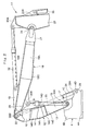
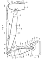
Fig. 1 is a front view illustrating a hydraulic excavator in accordance with an embodiment of the present invention; -
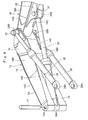
Fig. 2 is an enlarged front view of essential portions which is partly cut away, illustrating a revolving frame, a first boom, a second boom, a positioning cylinder, and the like shown inFig.1 ; -
Fig. 3 is an enlarged front view of essential portions which is partly cut away, similar toFig. 2 , illustrating a state in which the positioning cylinder is extended; -
Fig. 4 is an exploded perspective view showing the first boom, the second boom, the positioning cylinder, boom cylinders, a first boom connecting pin, and the like viewed from below; -
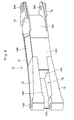
Fig. 5 is a perspective view showing the first boom as a single unit viewed from a cylinder accommodating section side; and -
Fig. 6 is an enlarged front view of essential portions similar toFig. 2 , illustrating a modification of the cylinder accommodating section. -
- 1:
- Hydraulic excavator (construction machine)
- 2:
- Lower traveling structure (vehicle body)
- 3:
- Upper revolving structure (vehicle body)
- 4:
- Revolving frame
- 11:
- Working mechanism
- 12:
- First boom
- 13:
- Foot portion
- 13A:
- Pin through hole
- 14:
- Rectangular tubular portion
- 14C:
- Upper flange plate (plate member)
- 14E':
- Proximal end side closing plate (plate member)
- 15, 15':
- Cylinder accommodating section
- 17:
- First boom connecting pin
- 18:
- Second boom
- 20:
- Positioning cylinder bracket (cylinder bracket)
- 22:
- Second boom connecting pin
- 28:
- Boom cylinder
- 30:
- Positioning cylinder
- 30A:
- Bottom side mounting eye (proximal end side)
- 30B:
- Rod side mounting eye (distal end side)
- Hereafter, with reference to the accompanying drawings, a detailed description will be given of an embodiment of a construction machine in accordance with the present invention by citing as an example a case in which the present invention is applied to a wheel type hydraulic excavator.
- In the drawings, designated at 1 is a wheel type hydraulic excavator as a construction machine, and the
hydraulic excavator 1 is largely constituted by an automotive wheel typelower traveling structure 2, an upper revolvingstructure 3 which is swingably mounted on thelower traveling structure 2 and constitutes a vehicle body together with thelower traveling structure 2, and a below-describedworking mechanism 11 which is liftably provided on the front side of the upper revolvingstructure 3. - The
lower traveling structure 2 is constituted by atruck frame 2A and front, rear, left, andright wheels 2B, which are provided on thistruck frame 2A and are driven by hydraulic motors (not shown). Thelower traveling structure 2 propels itself on roads and work sites as therespective wheels 2B are driven. - The upper revolving
structure 3 is largely constituted by a revolvingframe 4 serving as a base which is swingably mounted on thetruck frame 2A of thelower traveling structure 2, acab 5 provided on the front left side of the revolvingframe 4 to define an operation cabin, a counterweight 6 provided on a rear end side of the revolvingframe 4 to keep a weight balance with the workingmechanism 11, ahousing cover 7 provided on the front side of the counterweight 6 to accommodate an engine, a hydraulic pump, and the like (none are shown), and an operatingoil tank 8 and afuel tank 9 which are provided on the front side of thehousing cover 7. - Here, the revolving
frame 4 constitutes a rigid support structural body including a thick-walled bottom plate 4A extending in the frontward and rearward directions and left and rightvertical plates 4B (only the right side is shown) provided uprightly on thebottom plate 4A and extending in the frontward and rearward directions with a predetermined interval therebetween in the leftward and rightward directions, as shown inFig. 2 and the like. Aboom bracket portion 4C to which a proximal end side of a below-describedfirst boom 12 is rotatably mounted, and acylinder bracket portion 4D to which a proximal end side of a below-describedboom cylinder 28 is rotatably mounted, are provided on a front portion side of each of the left and rightvertical plates 4B. Meanwhile, the counterweight 6 is arranged to be provided on rear end sides of the left and rightvertical plates 4B. In this case, the position of theboom bracket portion 4C is located rearwardly of the position of thecylinder bracket portion 4D in the frontward and rearward directions and is located higher in an upward and downward directions than the same. - Denoted at 11 is the working mechanism which is provided liftably on the front side of the revolving
frame 4 for constituting the upper revolvingstructure 3. The workingmechanism 11 is for performing such as the operation of excavating earth and sand and is constituted by thefirst boom 12, asecond boom 18, anarm 3, abucket 25, the pair ofboom cylinders 28, apositioning cylinder 30, anarm cylinder 32, abucket cylinder 33, and the like, which will be described hereinafter. - Indicated at 12 is the first boom which is provided rotatably on the
boom bracket portion 4C of the revolvingframe 4. Thefirst boom 12, together with the below-describedsecond boom 18, constitutes a two-piece boom. As shown inFigs. 2 to 5 , thefirst boom 12 is largely constituted by left andright foot portions 13 constituted by solid cast bodies disposed with an interval therebetween in the leftward and rightward directions and a rectangulartubular portion 14 constituted by a plate-worked hollow structure secured to distal end sides of the left andright foot portions 13. - In this case, the left and
right foot portions 13 located at the proximal end side of thefirst boom 12 are respectively constituted by solid cast bodies formed of cast iron. Namely, thefoot portions 13 are respectively formed by casting means such that they have a substantially half length of the length dimension of thefirst boom 12, that their proximal end sides become thick in the leftward and rightward directions, and that they become gradually thinner from the proximal end sides toward their distal end sides. Thefoot portions 13 extend in the longitudinal direction while keeping a fixed interval therebetween, and a pin throughhole 13A, into which a below-described firstboom connecting pin 17 is inserted, is provided in a proximal end side of each of thefoot portions 13 in such a manner as to extend in the leftward and rightward directions. A below-described cylinderaccommodating section 15 is arranged to be formed between the left andright foot portions 13. - Meanwhile, the rectangular
tubular portion 14 which is located on the distal end side of thefirst boom 12 is formed as a plate-worked hollow structure by welding steel plates. Namely, the rectangulartubular portion 14 is formed as a rectangular tubular body having a cross-sectional rectangular shape by left andright web plates lower flange plates web plates - The distal end sides of the left and
right foot portions 13 in a state of having entered the proximal end side of the rectangulartubular portion 14 are firmly joined by welding to the left andright web plates lower flange plates tubular portion 14. In this case, theupper flange plate 14C extends to a part in the vicinity of the pin throughhole 13A along the left andright foot portions 13, and is welded over substantially entire regions of the left andright foot portions 13. - The proximal end side of the rectangular
tubular portion 14, namely, a position surrounded by a longitudinally intermediate portion of theupper flange plate 14C, the proximal end side of thelower flange plate 14D, and the left andright foot portions 13, is joined by a proximal endside closing plate 14E. Accordingly, the proximal end side of the rectangulartubular portion 14 is closed by this proximal endside closing plate 14E. Meanwhile, a distal endside closing plate 14F, which is bent substantially in a U-shape, is joined by welding to the distal end side of the rectangulartubular portion 14, namely, distal end portions of the upper andlower flange plates tubular portion 14. Accordingly, the distal end side of the rectangulartubular portion 14 is closed by the distal endside closing plate 14F. - Indicated at 15 is the cylinder accommodating section provided in the
first boom 12. Thecylinder accommodating section 15 accommodates a part (proximal end side) of the below-describedpositioning cylinder 30. Here, thecylinder accommodating section 15 is formed in that position of thefirst boom 12 which opposes thepositioning cylinder 30. Namely, thecylinder accommodating section 15 is formed as a recessed groove portion which is surrounded by the left andright foot portions 13, theupper flange plate 14C of the rectangulartubular portion 14 and the proximal endside closing plate 14E of the rectangulartubular portion 14, and extends in the longitudinal direction along the left and right foot portions 13 (seeFig. 5 ). - In this case, an innermost recessed portion (outward surface) of the
cylinder accommodating section 15 is closed by theupper flange plate 14C serving as a plate member, and an inward surface thereof is open. In consequence, the proximal end side (in the embodiment, the cylinder tube side) of thepositioning cylinder 30 which is accommodated in thecylinder accommodating section 15 can be protected from the ingress of earth and sand, etc. It is possible to increase the strength of thecylinder accommodating section 15. - Indicated at 16 are left and right brackets which are provided at the distal end portion of the rectangular
tubular portion 14. The proximal end side of the below-describedsecond boom 18 is rotatably attached to the left andright brackets 16. Here, the left andright brackets 16 are formed of thick flat plates in a substantially triangular shape, and are joined by welding to the distal end portions of the left andright web plates side closing plate 14F for constituting the rectangulartubular portion 14. A pin throughhole 16A, into which a below-described secondboom connecting pin 22 is inserted, is bored in the distal end side of each of thebrackets 16. - Denoted at 17 is the first boom connecting pin for connecting the
boom bracket portion 4C of the revolvingframe 4 and the proximal end side of thefirst boom 12. The firstboom connecting pin 17 rotatably supports thefirst boom 12 with respect to theboom bracket portion 4C of the revolvingframe 4. The firstboom connecting pin 17 is inserted in the pin throughholes 13A of the left andright foot portions 13 for constituting thefirst boom 12 and in theboom bracket portion 4C. In consequence, the distal end side of thefirst boom 12 is arranged to be rotated vertically (tilted vertically) about the firstboom connecting pin 17 to theboom bracket portion 4C. The proximal end side of thepositioning cylinder 30 is also arranged to be mounted on the firstboom connecting pin 17 coaxially therewith. - Next, indicated at 18 is the second boom which is rotatably attached to the distal end side of the
first boom 12. Thesecond boom 18, together with the above-describedfirst boom 12, constitutes the two-piece boom. Accordingly, as thepositioning cylinder 30 is extended or contracted, thesecond boom 18 is tilted vertically to thefirst boom 12. Here, thesecond boom 18 is formed as a hollow rectangular tubular body (plate-worked structure) having a cross-sectional rectangular shape over a substantially entire region in its longitudinal direction by left andright web plates 18A (only the right side is shown) opposing each other with a fixed interval therebetween in the leftward and rightward directions and by upper andlower flange plates 18C and 18D opposing each other in the upward and downward directions with theweb plates 18A sandwiched therebetween. - Left and right
arm cylinder brackets 19, to which the below-describedarm cylinder 32 is mounted, are provided at the proximal end side of theupper flange plate 18B for constituting thesecond boom 18. Meanwhile, left and rightpositioning cylinder brackets 20, to which thepositioning cylinder 30 is mounted, are provided at the proximal end side of thelower flange plate 18C at a position slightly spaced apart from the below-described secondboom connecting pin 22. Further, left andright arm brackets 21 are provided at the distal end side of thesecond boom 18, and the proximal end side of the below-describedarm 23 is arranged to be rotatably mounted on thearm brackets 21. - Denoted at 22 is the second boom connecting pin for connecting the distal end side of the
first boom 12 and the proximal end side of thesecond boom 18. The secondboom connecting pin 22 rotatably supports thesecond boom 18 with respect to thefirst boom 12. The secondboom connecting pin 22 is inserted in the pin throughholes 16A of thebrackets 16 provided on thefirst boom 12 and in a boss portion (not shown) provided in the proximal end side of thesecond boom 18. In consequence, the distal end side of thesecond boom 18 is arranged to be rotated vertically about the secondboom connecting pin 22 to thefirst boom 12. - Here, both end sides of the second
boom connecting pin 22 are adapted to project from thebrackets 16 of thefirst boom 12 in the leftward and rightward directions. A rodside mounting eye 28B of each of the below-described left andright boom cylinders 28 is arranged to be rotatably mounted at a projecting end portion of the secondboom connecting pin 22 projecting from the bracket 16 (seeFig. 4 ). - Denoted at 23 is the arm which is rotatably mounted to the distal end side of the
second boom 18. Thearm 23 is formed as a rectangular tubular body (plate-worked structure) having a cross-sectional rectangular shape surrounded by left and right web plates and upper and lower flange plates. Anarm cylinder bracket 23A, to which the below-describedarm cylinder 32 is mounted, is provided at the proximal end side of thearm 23, and abucket cylinder bracket 23B, to which the below-describedbucket cylinder 33 is mounted, is also provided thereon. A boss portion (not shown), into which a below-describedarm connecting pin 24 is inserted, is provided at the proximal end side of thearm 23 in such a manner as to be located on the opposite side to the aforementionedbucket cylinder bracket 23B. A boss portion (not shown), into which a below-describedbucket connecting pin 26 is inserted, is provided at the distal end side of thearm 23. - Indicated at 24 is the arm connecting pin for connecting the distal end side of the
second boom 18 and thearm 23. Thearm connecting pin 24 rotatably supports thearm 23 with respect to thesecond boom 18. Thearm connecting pin 24 is inserted in thearm bracket 21 of thesecond boom 18 and a boss portion (not shown) provided at the proximal end side of thearm 23. In consequence, the distal end side of thearm 23 is arranged to be rotated vertically (tilted vertically) about thearm connecting pin 24 to thesecond boom 18. - Indicated at 25 is the bucket which is rotatably mounted at the distal end side of the
arm 23. Thebucket 25 is used for the operation of excavating earth and sand, etc. As shown inFig. 1 , left andright brackets 25A is provided at the proximal end side of thebucket 25, and thebrackets 25A are mounted at the distal end side of thearm 23 by means of thebucket connecting pin 26. Further, two pairs ofbucket links 27 are each provided between thebracket 25A of thebucket 25 and thearm 23, and the distal end side of the below-describedbucket cylinder 33 is arranged to be connected to each of the bucket links 27. - Denoted at 28 are the left and right boom cylinders which are provided on the left and right sides with the
first boom 12 sandwiched therebetween. These left andright boom cylinders 28 tilt thefirst boom 12 vertically to the revolvingframe 4. Here, a bottomside mounting eye 28A is provided on the cylinder tube bottom side (proximal end side) of theboom cylinder 28, and the bottomside mounting eye 28A is rotatably mounted to thecylinder bracket portion 4D of the revolvingframe 4 through a connectingpin 29 in such a manner as to be located forwardly of the firstboom connecting pin 17. - Meanwhile, the rod
side mounting eye 28B is provided at the rod distal end side of theboom cylinder 28. The rodside mounting eye 28B is rotatably mounted on the secondboom connecting pin 22. Thus, the rodside mounting eye 28B constituting the distal end side of theboom cylinder 28 is mounted coaxially with the proximal end side of thesecond boom 18 by making use of the secondboom connecting pin 22 connecting thefirst boom 12 and thesecond boom 18. - Designated at 30 is the positioning cylinder for tilting the
second boom 18 vertically to thefirst boom 12. Thispositioning cylinder 30 adjusts an angle between thefirst boom 12 and thesecond boom 18 about the secondboom connecting pin 22, namely, a bending angle of thesecond boom 18 with respect to thefirst boom 12. - Here, a bottom
side mounting eye 30A is provided on the cylinder tube bottom side (proximal end side) of thepositioning cylinder 30. The bottomside mounting eye 30A is rotatably mounted on the firstboom connecting pin 17 in such a manner as to be positioned between the left andright foot portions 13 constituting thefirst boom 12. Thus, the bottomside mounting eye 30A constituting the proximal end side of thepositioning cylinder 30 is mounted coaxially with the proximal end side of thefirst boom 12 by making use of the firstboom connecting pin 17 connecting the revolvingframe 4 and thefirst boom 12. In this case, a connectingpin 31 disposed at a position in the vicinity of the secondboom connecting pin 22. - Meanwhile, a rod
side mounting eye 30B is provided on the rod side (distal end side) of thepositioning cylinder 30. The rodside mounting eye 30B is rotatably mounted through the connectingpin 31 to thepositioning cylinder brackets 20 provided on thelower flange plate 18C of thesecond boom 18. - Accordingly, as the
positioning cylinder 30 is extended or contracted, thesecond boom 18 is arranged to be tilted vertically about the secondboom connecting pin 22 to thefirst boom 12, making it possible to appropriately adjust the bending angle of thesecond boom 18 with respect to thefirst boom 12, as shown inFigs. 1 and3 . - In this case, since the
cylinder accommodating section 15, which is surrounded by the left andright foot portions 13, theupper flange plate 14C of the rectangulartubular portion 14, and the proximal endside closing plate 14E of the rectangulartubular portion 14, is provided in that position of thefirst boom 12 which opposes thepositioning cylinder 30, a part of thepositioning cylinder 30 can be accommodated in thiscylinder accommodating section 15. In consequence, even in the case when the bottomside mounting eye 30A constituting the proximal end side of thepositioning cylinder 30 is mounted on the firstboom connecting pin 17 coaxially with the left andright foot portions 13 of thefirst boom 12, thefirst boom 12 and thepositioning cylinder 30 do not interfere with each other. As a result, the construction provided is such that thepositioning cylinder 30 can be operated properly, and in the case when excavating operation is performed by use of the workingmechanism 11, it is possible to avoid thepositioning cylinder 30 from colliding against the earth and sand, etc. - Indicated at 32 is the arm cylinder which is provided between the
second boom 18 and thearm 23. The cylinder tube bottom side of thearm cylinder 32 is pin-coupled to thearm cylinder bracket 19 of thesecond boom 18, while the rod side of thearm cylinder 32 is pin-coupled to thearm cylinder bracket 23A of thearm 23. Accordingly, as thearm cylinder 32 is extended or contracted, thearm 23 is arranged to rotate vertically at the distal end side of thesecond boom 18. - Indicated at 33 is the bucket cylinder which is provided between the
arm 23 and thebucket link 27. The cylinder tube bottom side of thebucket cylinder 33 is pin-coupled to thebucket cylinder bracket 23B of thearm 23, while the rod side of thebucket cylinder 33 is pin-coupled to an intermediate portion of thebucket link 27. Accordingly, as thebucket cylinder 33 is extended or contracted, thebucket 25 is arranged to rotate vertically at the distal end side of thearm 23. - The
hydraulic excavator 1 in accordance with this embodiment has the workingmechanism 11 described above, and in the case when such as the operation of excavating earth and sand is performed by use of this workingmechanism 11, thehydraulic excavator 1 propels itself to a work site by the wheel typelower traveling structure 2. - Here, during the traveling of the
hydraulic excavator 1, as thepositioning cylinder 30 is contracted, as shown inFigs. 1 and2 , thesecond boom 18 is drawn toward thefirst boom 12 side, thereby making it possible to fold thewhole working mechanism 11 compactly. In consequence, it is possible to enhance the safety of thehydraulic excavator 1 during traveling. - Further, in the case when excavating operation is performed by use of the working
mechanism 11 of thehydraulic excavator 1, thepositioning cylinder 30 is extended or contracted according to, for example, the depth of a pit to be dug, thereby appropriately adjusting the bending angle of thesecond boom 18 with respect to thefirst boom 12. As thepositioning cylinder 30 is thus extended or contracted before the excavating operation, for example, as shown inFig. 3 , the bending angle of thesecond boom 18 with respect to thefirst boom 12 can be set to be large. Accordingly, as theboom cylinders 28 are moved in this state, thefirst boom 12 and thesecond boom 18 can be tilted vertically to the revolvingframe 4 while maintaining a fixed bending angle. - As the
first boom 12 and thesecond boom 18 which are thus integrated with a fixed bending angle are tilted vertically by theboom cylinders 28, and thearm cylinder 32 and thebucket cylinder 33 are extended or contracted, it is possible to excavate a pit in the ground by means of thebucket 25. - In this case, the bottom
side mounting eye 30A constituting the proximal end side of thepositioning cylinder 30 is mounted on the firstboom connecting pin 17 for connecting the proximal end side of thefirst boom 12 to the revolvingframe 4. As a result, it is unnecessary to secure a bracket on the outward surface of the first boom and mount the proximal end side of the positioning cylinder to this bracket in the manner required in the conventional art. For this reason, even when a load has acted on thefirst boom 12 due to the excavating operation and thefirst boom 12 has undergone deformation, the bottomside mounting eye 30A of thepositioning cylinder 30 can be kept reliably mounted on the firstboom connecting pin 17, so that thepositioning cylinder 30 can be operated stably over extended periods of time. - The construction provided is such that the
cylinder accommodating section 15, which is surrounded by the left andright foot portions 13, theupper flange plate 14C of the rectangulartubular portion 14, and the proximal endside closing plate 14E of the rectangulartubular portion 14, is arranged to be provided in that position of thefirst boom 12 which opposes thepositioning cylinder 30. In consequence, even in the case when the bottomside mounting eye 30A constituting the proximal end side of thepositioning cylinder 30 is mounted on the firstboom connecting pin 17, a part (proximal end side) of thepositioning cylinder 30 can be accommodated in thecylinder accommodating section 15 of thefirst boom 12. - As a result, the
first boom 12 and thepositioning cylinder 30 do not interfere with each other, and thepositioning cylinder 30 can be operated properly. As thepositioning cylinder 30 is accommodated in thecylinder accommodating section 15 of thefirst boom 12, it is possible to avoid such as the earth and sand from colliding against thepositioning cylinder 30, thereby making it possible to protect thepositioning cylinder 30. Thecylinder accommodating section 15, in particular, has its outward surface (innermost recessed portion) closed by theupper flange plate 14C, the proximal end side of thepositioning cylinder 30 which is accommodated in thecylinder accommodating section 15 can be protected from the ingress of the earth and sand, and so forth. - The construction provided is such that the
positioning cylinder brackets 20 for mounting the rodside mounting eye 30B of thepositioning cylinder 30 are provided on thelower flange plate 18C of thesecond boom 18 in such a manner as to be located in the vicinity of the secondboom connecting pin 22. For this reason, thepositioning cylinder 30 can be disposed in such a manner as to be sandwiched between the inward surface of thefirst boom 12 and the inward surface of thesecond boom 18. As a result, when performing the excavating operation, thepositioning cylinder 30 can be prevented from interfering with obstacles which are present in the surroundings of the workingmechanism 11, thereby making it possible to secure a working range widely. - Further, the construction provided is such that the rod
side mounting eye 28B serving as the distal end side of theboom cylinder 28 is arranged to be mounted coaxially by making use of the well-known secondboom connecting pin 22 connecting thefirst boom 12 and thesecond boom 18. For this reason, since a bracket for mounting the distal end side of thearm cylinder 28 need not be provided on the outward surface of thefirst boom 12, as compared with the case when the bracket for mounting the boom cylinder is provided separately on the outward surface of thefirst boom 12, the number of parts can be reduced, thereby making it possible to lower the manufacturing cost of thefirst boom 12 correspondingly. - It should be noted that in the above-described embodiment the case is illustrated in which the
cylinder accommodating section 15 of thefirst boom 12 is formed by the space surrounded by theupper flange plate 14C of the rectangulartubular portion 14, the left andright foot portions 13, and the proximal endside closing plate 14E extending in a direction substantially perpendicular to the longitudinal direction of thefoot portion 13. However, the present invention is not limited to the same, and may be constructed as in a modification shown inFig. 6 . - Namely, in
Fig. 6 , indicated at 14E' is a proximal end side closing plate in accordance with the modification. The proximal endside closing plate 14E' is disposed in such a manner as to extend along the longitudinal direction of thepositioning cylinder 30 in a state in which thepositioning cylinder 30 is minimally contracted. Then, a space which is surrounded by the proximal endside closing plate 14E', theupper flange plate 14C of the rectangulartubular portion 14, and the left andright foot portions 13 is formed as a cylinder accommodating section 15'. In this case, the proximal endside closing plate 14E' serves as a plate member for closing the innermost recessed portion of the cylinder accommodating section 15'. - In the above-described embodiment, the case has been illustrated in which the
first boom 12 is constituted by the left andright foot portions 13 formed of cast bodies and the rectangulartubular portion 14 constituted by a plate-worked structure joined to thefoot portions 13 by welding, and thecylinder accommodating section 15 is formed between the left andright foot portions 13. However, the present invention is not limited to the same and may be configured such that the overall first boom including the left and right foot portions is formed by a hollow plate-worked structure, and that position of the first boom, constituted by this plate-worked structure, which opposes thepositioning cylinder 30 is recessed to provide a recessed cylinder accommodating section. - Meanwhile, in the embodiment, as for the
positioning cylinder 30, the case has been illustrated in which the bottomside mounting eye 30A is connected to the firstboom connecting pin 17 coaxially therewith. However, the present invention is not limited to the same, and the rodside mounting eye 30B of thepositioning cylinder 30 may be arranged to be connected to the firstboom connecting pin 17 coaxially therewith. In this case, the rodside mounting eye 30B constitutes the proximal end side, and the bottomside mounting eye 30A constitutes the distal end side. - Further, in the above-described embodiment, a description has been given by citing as an example of the construction machine the wheel type
hydraulic excavator 1 having thewheels 2B. However, the present invention is not limited to the same, and may also be applied to, for example, a crawler type hydraulic excavator insofar as it has a boom of the two-piece boom type consisting of the first boom and the second boom.
Claims (6)
- A construction machine comprising an automotive vehicle body and a working mechanism which is liftably provided on said vehicle body, said working mechanism including a first boom whose proximal end side is connected to said vehicle body through a first boom connecting pin, a second boom connected to a distal end side of said first boom through a second boom connecting pin, a boom cylinder for tilting said first boom vertically to said vehicle body, and a positioning cylinder for tilting said second boom vertically so as to adjust a bending angle of said second boom with respect to said first boom, characterized in that;
a proximal end side of said positioning cylinder is arranged to be mounted coaxially with the proximal end side of said first boom by use of said first boom connecting pin, and a distal end side of said positioning cylinder is arranged to be mounted on said second boom. - The construction machine according to claim 1, wherein a cylinder accommodating section for accommodating a part of said positioning cylinder is arranged to be provided in said first boom at a position opposing said positioning cylinder.
- The construction machine according to claim 1, wherein said first boom is constituted by left and right foot portions disposed in such a manner as to be spaced apart from each other in a leftward and rightward directions and a rectangular tubular portion secured to distal end sides of said left and right foot portions, a pin through hole into which said first boom connecting pin is inserted being provided in each of proximal end sides of said left and right foot portions, a cylinder accommodating section for accommodating a part of said positioning cylinder being provided between said left and right foot portions, the proximal end side of said positioning cylinder being arranged to be disposed in said cylinder accommodating section.
- The construction machine according to claim 2 or 3, wherein an innermost recessed portion of said cylinder accommodating section is arranged to be closed by a plate member provided on said first boom.
- The construction machine according to claim 1, wherein a cylinder bracket is provided on an inward surface of said second boom at a position spaced apart forwardly of a position of said second boom connecting pin, and the distal end side of said positioning cylinder is arranged to be mounted to said cylinder bracket.
- The construction machine according to claim 1, wherein a proximal end side of said boom cylinder is mounted on said vehicle body in such a manner as to be located forwardly of said first boom connecting pin, and a distal end side of said boom cylinder is arranged to be mounted coaxially with a proximal end side of said second boom by use of said second boom connecting pin.
Applications Claiming Priority (2)
| Application Number | Priority Date | Filing Date | Title |
|---|---|---|---|
| JP2008139443 | 2008-05-28 | ||
| PCT/JP2009/055975 WO2009145000A1 (en) | 2008-05-28 | 2009-03-25 | Construction machine |
Publications (1)
| Publication Number | Publication Date |
|---|---|
| EP2290163A1 true EP2290163A1 (en) | 2011-03-02 |
Family
ID=41376886
Family Applications (1)
| Application Number | Title | Priority Date | Filing Date |
|---|---|---|---|
| EP09754508A Withdrawn EP2290163A1 (en) | 2008-05-28 | 2009-03-25 | Construction machine |
Country Status (5)
| Country | Link |
|---|---|
| EP (1) | EP2290163A1 (en) |
| JP (1) | JPWO2009145000A1 (en) |
| KR (1) | KR20110021703A (en) |
| CN (1) | CN101960074A (en) |
| WO (1) | WO2009145000A1 (en) |
Cited By (1)
| Publication number | Priority date | Publication date | Assignee | Title |
|---|---|---|---|---|
| JP5756171B2 (en) * | 2011-05-12 | 2015-07-29 | 日立建機株式会社 | Construction machinery |
Families Citing this family (3)
| Publication number | Priority date | Publication date | Assignee | Title |
|---|---|---|---|---|
| JP5708369B2 (en) * | 2011-08-24 | 2015-04-30 | コベルコ建機株式会社 | Work machine |
| CN104846860B (en) * | 2015-05-28 | 2017-08-25 | 南宁远卓新能源科技有限公司 | A kind of three sections of arm-type excavators |
| JP2019127725A (en) * | 2018-01-23 | 2019-08-01 | 株式会社クボタ | Work machine, control method of work machine, program, and storage medium for the same |
Family Cites Families (6)
| Publication number | Priority date | Publication date | Assignee | Title |
|---|---|---|---|---|
| JP3304186B2 (en) * | 1994-03-07 | 2002-07-22 | 日立建機株式会社 | Swing type excavator |
| JPH08260503A (en) * | 1995-03-22 | 1996-10-08 | Kubota Corp | Boom structure of backhoe |
| JP3239059B2 (en) * | 1995-12-18 | 2001-12-17 | 新キャタピラー三菱株式会社 | Construction machinery |
| JPH1193199A (en) * | 1997-09-16 | 1999-04-06 | Hitachi Constr Mach Co Ltd | Front controller for articulated construction machine |
| JP2002220851A (en) | 2001-01-25 | 2002-08-09 | Hitachi Constr Mach Co Ltd | Hydraulic backhoe |
| JP4444606B2 (en) * | 2003-09-18 | 2010-03-31 | 日立建機株式会社 | Construction machinery |
-
2009
- 2009-03-25 CN CN2009801077883A patent/CN101960074A/en active Pending
- 2009-03-25 KR KR1020107013644A patent/KR20110021703A/en not_active Application Discontinuation
- 2009-03-25 EP EP09754508A patent/EP2290163A1/en not_active Withdrawn
- 2009-03-25 JP JP2010514407A patent/JPWO2009145000A1/en active Pending
- 2009-03-25 WO PCT/JP2009/055975 patent/WO2009145000A1/en active Application Filing
Non-Patent Citations (1)
| Title |
|---|
| See references of WO2009145000A1 * |
Cited By (1)
| Publication number | Priority date | Publication date | Assignee | Title |
|---|---|---|---|---|
| JP5756171B2 (en) * | 2011-05-12 | 2015-07-29 | 日立建機株式会社 | Construction machinery |
Also Published As
| Publication number | Publication date |
|---|---|
| KR20110021703A (en) | 2011-03-04 |
| CN101960074A (en) | 2011-01-26 |
| WO2009145000A1 (en) | 2009-12-03 |
| JPWO2009145000A1 (en) | 2011-10-06 |
Similar Documents
| Publication | Publication Date | Title |
|---|---|---|
| KR100693978B1 (en) | Swiveling work machine | |
| KR100483337B1 (en) | Frame type tractor | |
| JP4247222B2 (en) | Excavator fixing structure of tractor loader backhoe | |
| JP2010112094A (en) | Construction machine | |
| KR100976023B1 (en) | Boom for excavation machine | |
| JP2007205100A (en) | Body frame of construction machinery and the construction machinery | |
| KR101837220B1 (en) | Construction machine swing frame | |
| EP2290163A1 (en) | Construction machine | |
| KR100965036B1 (en) | Arm for excavation machine | |
| JP2007063839A (en) | Protection structure for construction equipment, and cab for construction equipment | |
| JP3967501B2 (en) | Swivel construction machine | |
| JP2003129522A (en) | Revolving frame of construction machinery | |
| US20080202779A1 (en) | Rear Implement Mounting Frame Construction for Tractor | |
| JP4908141B2 (en) | Construction machinery | |
| JP3917448B2 (en) | Tractor front guard device | |
| WO2017072845A1 (en) | Front loader | |
| JP2009133084A (en) | Offset boom type front device | |
| JP5138654B2 (en) | Construction machine swivel frame | |
| JP2003096810A (en) | Offset boom type construction machinery | |
| JP2007254986A (en) | Lift arm for skid steering loader | |
| JP2002339403A (en) | Turning frame of construction machine | |
| JP2002339404A (en) | Turning frame of construction machine | |
| JP2001317084A (en) | Slewing frame for construction machine and assembly method therefor | |
| JP6676565B2 (en) | Work machine | |
| JP2003034945A (en) | Offset boom tape construction machinery |
Legal Events
| Date | Code | Title | Description |
|---|---|---|---|
| PUAI | Public reference made under article 153(3) epc to a published international application that has entered the european phase |
Free format text: ORIGINAL CODE: 0009012 |
|
| 17P | Request for examination filed |
Effective date: 20101228 |
|
| AK | Designated contracting states |
Kind code of ref document: A1 Designated state(s): AT BE BG CH CY CZ DE DK EE ES FI FR GB GR HR HU IE IS IT LI LT LU LV MC MK MT NL NO PL PT RO SE SI SK TR |
|
| AX | Request for extension of the european patent |
Extension state: AL BA RS |
|
| DAX | Request for extension of the european patent (deleted) | ||
| STAA | Information on the status of an ep patent application or granted ep patent |
Free format text: STATUS: THE APPLICATION HAS BEEN WITHDRAWN |
|
| 18W | Application withdrawn |
Effective date: 20120509 |