EP2289806B1 - Verfahren und Vorrichtung zur Ausgabe einer vorbestimmten festen Menge von vorgespannten Folien in Bezug auf einen Lastenumfang - Google Patents
Verfahren und Vorrichtung zur Ausgabe einer vorbestimmten festen Menge von vorgespannten Folien in Bezug auf einen Lastenumfang Download PDFInfo
- Publication number
- EP2289806B1 EP2289806B1 EP10184207.8A EP10184207A EP2289806B1 EP 2289806 B1 EP2289806 B1 EP 2289806B1 EP 10184207 A EP10184207 A EP 10184207A EP 2289806 B1 EP2289806 B1 EP 2289806B1
- Authority
- EP
- European Patent Office
- Prior art keywords
- load
- film
- stretch
- stretched film
- dispenser
- Prior art date
- Legal status (The legal status is an assumption and is not a legal conclusion. Google has not performed a legal analysis and makes no representation as to the accuracy of the status listed.)
- Not-in-force
Links
Images


Classifications
-
- B—PERFORMING OPERATIONS; TRANSPORTING
- B65—CONVEYING; PACKING; STORING; HANDLING THIN OR FILAMENTARY MATERIAL
- B65B—MACHINES, APPARATUS OR DEVICES FOR, OR METHODS OF, PACKAGING ARTICLES OR MATERIALS; UNPACKING
- B65B11/00—Wrapping, e.g. partially or wholly enclosing, articles or quantities of material, in strips, sheets or blanks, of flexible material
- B65B11/02—Wrapping articles or quantities of material, without changing their position during the wrapping operation, e.g. in moulds with hinged folders
- B65B11/025—Wrapping articles or quantities of material, without changing their position during the wrapping operation, e.g. in moulds with hinged folders by webs revolving around stationary articles
-
- B—PERFORMING OPERATIONS; TRANSPORTING
- B65—CONVEYING; PACKING; STORING; HANDLING THIN OR FILAMENTARY MATERIAL
- B65B—MACHINES, APPARATUS OR DEVICES FOR, OR METHODS OF, PACKAGING ARTICLES OR MATERIALS; UNPACKING
- B65B11/00—Wrapping, e.g. partially or wholly enclosing, articles or quantities of material, in strips, sheets or blanks, of flexible material
- B65B2011/002—Prestretching mechanism in wrapping machines
-
- B—PERFORMING OPERATIONS; TRANSPORTING
- B65—CONVEYING; PACKING; STORING; HANDLING THIN OR FILAMENTARY MATERIAL
- B65B—MACHINES, APPARATUS OR DEVICES FOR, OR METHODS OF, PACKAGING ARTICLES OR MATERIALS; UNPACKING
- B65B2210/00—Specific aspects of the packaging machine
- B65B2210/14—Details of wrapping machines with web dispensers for application of a continuous web in layers onto the articles
- B65B2210/16—Details of wrapping machines with web dispensers for application of a continuous web in layers onto the articles the web dispenser travelling around the article along a non-rotating ring
-
- B—PERFORMING OPERATIONS; TRANSPORTING
- B65—CONVEYING; PACKING; STORING; HANDLING THIN OR FILAMENTARY MATERIAL
- B65B—MACHINES, APPARATUS OR DEVICES FOR, OR METHODS OF, PACKAGING ARTICLES OR MATERIALS; UNPACKING
- B65B2210/00—Specific aspects of the packaging machine
- B65B2210/14—Details of wrapping machines with web dispensers for application of a continuous web in layers onto the articles
- B65B2210/18—Details of wrapping machines with web dispensers for application of a continuous web in layers onto the articles the web dispenser being mounted on a rotary ring
Definitions
- the present invention relates to methods and apparatus for wrapping a load with packaging material, and more particularly, stretch wrapping.
- Stretch wrapping can be performed as an inline, automated packaging technique that dispenses and wraps packaging material in a stretch condition around a load on a pallet to cover and contain the load.
- Pallet stretch wrapping whether accomplished by a turntable, rotating arm, vertical rotating ring, or horizontal rotating ring, typically covers the four vertical sides of the load with a stretchable film such as polyethylene film. In each of these arrangements, relative rotation is provided between the load and the packaging material dispenser to wrap packaging material about the sides of the load.
- Stretch wrapping machines provide relative rotation between a stretch wrap packaging dispenser and a load either by driving the stretch wrap packaging dispenser around a stationary load or rotating the load on a turntable. Upon relative rotation, packaging material is wrapped on the load.
- Ring style stretch wrappers generally include a roll of packaging material mounted in a dispenser, which rotates about the load on a ring.
- Wrapping rings are categorized as vertical rings or horizontal rings. Vertical rings move vertically between an upper and lower position to wrap film around a load. In a vertical ring, as in turntable and rotating wrap arm apparatuses, the four vertical sides of the load are wrapped, along the height of the load. Horizontal rings are stationary and the load moves through the ring, usually on a conveyor, as the dispenser rotates around the load to wrap packaging material around the load. In the horizontal ring, the length of the load is wrapped. As the load moves through the ring and off the conveyor, the packaging material slides off the conveyor (surface supporting the load) and into contact with the load.
- the demand for packaging material varies, decreasing as the packaging material approaches contact with a corner of the load and increasing after contact with the corner of the load.
- the variation in the demand rate is even greater than in a typical rectangular load.
- the variation is caused by a difference between the length and the width of the load.
- the variation is caused by a difference between the height of the load (distance above the conveyor) and the width of the load.
- This increase force is typically transmitted back to an electronic load cell, spring-loaded dancer interconnected with a sensing means, or by speed change to a torque control device. After the corner is passed the force on the film reduces as the film demand decreases. This force or speed is transmitted back to some device that in turn reduces the film supply to attempt to maintain a relatively constant wrap force.
- U.S. Patent No. 4,418,510 includes an embodiment that sets a pre-stretch roller speed to a reference speed faster or slower than the rotating load.
- This embodiment experienced no commercial success due the difficulty of practically achieving that process with market acceptable cost and satisfactory wrap performance. Accurately setting and maintaining the reference speeds with the disclosed embodiments proved problematic.
- US 4,302,920 A describes a stretch wrap packaging machine including a support frame and a rotatable frame rotatably mounted on the support frame.
- a dispenser is mounted on the rotatable frame to follow an orbital path.
- the dispenser has a web tensioning system which is selectably operable in a plurality of states.
- At least one actuation ring is moveably mounted on the support frame for cooperation with the tensioning system and selectively rendering the tensioning system operable in each of the plurality of states of operation throughout the orbital path.
- An activator moves the actuation ring to cooperate with the tensioning system.
- the tensioning system may include prestretch rollers connected by an engageable clutch.
- the tensioning system may also include at least one power assisted roller which is connected by a clutch to a power source.
- Film dispensers mounted on horizontally rotating rings present additional special issues concerning effectively wrapping at high speeds. All commercially available ring wrappers in use depend upon electrically powered motors to drive the pre-stretch film dispensers. The power for these motors must be transmitted to the rotating ring. This is typically done through electric slip rings mounted to the rotating ring with an electrical pick up finger mounted to the fixed frame. Alternately, others have attempted to charge a battery or run a generator during ring rotation. All of these devices suffer complexity, cost and maintenance issues. But even more importantly they add significant weight to the rotating ring which impacts its ability to accelerate and decelerate rapidly.
- Film dispensers mounted on vertically rotating rings have the additional problem of gravity forces added to centrifugal forces of high-speed rotation.
- High-speed wrappers have therefore required expensive and very heavy two part bearings to support the film dispensers.
- the presence of the outer race on these bearings has made it possible to provide a belt drive to the pre-stretch dispenser. This drive is taken through a clutch type torque device to deliver the variable demand rate required for wrap force desired.
- Object of the invention is to solve one or more of the above-mentioned problems.
- This object is achieved by providing a method of stretch wrapping a load according to claim 1. This object is further achieved by providing an apparatus for stretch wrapping a load according to claim 10. Preferable embodiments are given by the dependent claims.
- a method and apparatus for dispensing a predetermined fixed amount of pre-stretched film relative to load girth is provided.
- the present invention relates to a method of stretch wrapping a load.
- the method includes determining a girth of a load to be wrapped.
- the method also includes determining a fixed amount of pre-stretched film to be dispensed for each revolution of a film dispenser around the load based on the girth of the load.
- the method further includes rotating the film dispenser, mounted on a rotatable ring, around the load.
- the method further includes dispensing the fixed amount of pre-stretched film during each revolution of the film dispenser around the load to wrap the pre-stretched film around the load, wherein the fixed amount of pre-stretched film is dispensed independent of a speed of rotation of the film dispenser around the load.
- the present invention relates to an apparatus for stretch wrapping a load.
- the apparatus includes a non-rotating frame and a rotatable ring supported by the non-rotating frame.
- the apparatus also includes a film dispenser having a pre-stretch portion, the film dispenser being mounted on the rotatable ring.
- the apparatus further includes a drive mechanism configured to rotate the rotatable ring while driving the pre-stretch portion to dispense a predetermined length of pre-stretched film for each revolution of the rotatable ring.
- the drive mechanism includes multiple sprockets or a variable transmission for adjusting the predetermined length of pre-stretched film for each revolution of the rotatable ring.
- Fig. 1 is an isometric view of an apparatus for wrapping a load according to one aspect of the present invention
- Fig. 2 is a top view of an apparatus for wrapping a load according to one aspect of the present invention
- Fig. 3 is a side view of the apparatus of Fig. 2 ;
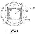
- Fig. 4 is a top view of a load being wrapped and illustrates the shortest wrap radius and the longest wrap radius
- Fig. 5 is an isometric view of a support structure for the rotatable ring of a stretch wrapping apparatus according to one aspect of the present invention
- Fig. 6 is an isometric view of a rotating ring, a fixed ring, a drive system and a dispenser of an apparatus according to one aspect of the present invention.
- Fig. 7 is an isometric view of an alternative embodiment of an apparatus for wrapping a load according to one aspect of the present invention.
- the present invention is related to a method and apparatus for dispensing a predetermined fixed amount of pre-stretched film per revolution of a dispenser around a load during a wrapping cycle.
- the apparatus includes a rotating ring, a film dispenser including a pre-stretch portion, the film dispenser being mounted on the rotating ring, and a drive system for rotating the ring and driving the pre-stretch rollers of the film dispenser.
- the fixed amount of pre-stretched film dispensed per revolution of the dispenser is predetermined based upon the girth of the load to be wrapped.
- Test results have shown that good wrapping performance in terms of load containment (wrap force) and optimum film use (efficiency) is obtained by dispensing a length of pre-stretched film that is between approximately 100% and approximately 130% of load girth, and preferably between 100% and 120% of load girth.
- a 102 cm x 122 cm (40 inch x 48 inch) load has a girth of 2 x (102+122) or 448 (2 x(40 + 48) or 176 inches).
- To dispense a length of pre-stretched film that is between 100% and 120% of the load girth for every revolution of the dispenser would require dispensing between approximately 448 cm (176 inches) and approximately 538 cm (211 inches) of pre-stretched film. Additional testing has shown that approximately 107% of load girth gives best results.
- the predetermined amount of pre-stretched film to be dispensed for each revolution of the dispenser would be approximately 478 cm (188 inches).
- the film dispenser travels a known distance around the load each revolution of the ring on which the dispenser travels.
- the speed at which the dispenser travels is irrelevant, because the same distance is covered by the dispenser during each revolution of the rotating ring regardless of the time it takes to perform the revolution.
- the film dispenser and ring are belt driven. That same belt is also used to drive the pre-stretch rollers. Once the amount of film needed per revolution is established, the next step is to determine how many revolutions of a downstream pre-stretch roller are needed during one revolution of the film dispenser in order to dispense the required amount of pre-stretched film.
- the downstream pre-stretch roller For example, if approximately 483 cm (190 inches) of film are needed per revolution of the ring/dispenser, one can measure the circumference of the downstream pre-stretch roller, for example 25,4 cm (10 inches), and know that each rotation of the downstream pre-stretch roller will dispense 25.4 cm (10 inches) of pre-stretched film. Therefore, in order to dispenser 483 cm (190 inches) of film during one revolution of the rotating ring and dispenser, the downstream pre-stretch roller must rotate 19 times (483 cm/25.4 cm (190 inches/10 inches)). Once the necessary number of revolutions of the downstream pre-stretch roller is known, it is possible to set the sprocket to, for example, 19 pre-stretch roller revolutions per one ring rotation.
- the pre-stretched film is dispensed between approximately 100% and approximately 130% of girth/ring revolution and the dispensing is mechanically controlled and precisely selectable by establishing a mechanical ratio of ring drive to final pre-stretch surface speed (e.g., number of pre-stretch roller revolutions/ring rotation).
- Drive components can be arranged for easy change of the amount of pre-stretch of the film or the percentage of load girth dispensed. Multiple sprockets or a variable transmission could be substituted for sprockets to enable changing the number of pre-stretch roller revolutions/ring quickly. No slip rings, motor, control box, force controls are required. As the rotating ring is driven, it drives the pre-stretch rollers through a fixed mechanical connection.
- the dispensing of the predetermined fixed amount of pre-stretched film/revolution of the rotating ring and dispenser is independent of wrap force or speed of the ring. It is also independent of load girth shape or placement of the load.
- the speed of the pre-stretch rollers is thus constant relative to the rotation of the ring. That is, for each revolution of the ring, regardless of the speed of the ring, the pre-stretch roller will complete a constant/fixed number of revolutions. If the ring speed increases, the amount of time it takes for the pre-stretch roller to complete the constant/fixed number of revolutions will decrease, but the same number of revolutions will be completed during one rotation of the ring. Similarly, if the ring speed decreases, the amount of time it takes for the pre-stretch roller to complete the constant/fixed number of revolutions will increase, but the same number of revolutions will be completed during one rotation of the ring.
- the rotating ring is powered for very rapid acceleration to over 50 rpm with an acceleration period of one second and a deceleration period of one second. Since the film feed is independent of the rotation speed as described above, there is no extra force on the film during acceleration or excess film during deceleration. If reduced force, below optimum wrapping force, is required during initial startup the ring can be reversed to create slack film at the end of the previous cycle. A one-way clutch may be included to prevent any backlash from film feed while the ring is reversed. The slack film remains well around the first corner of the load until the elasticity of the dispensed film can take it up.
- the variation in forces seen on the film illustrated above at a constant relative speed can be dampened very significantly by allowing a longer stretch of film between the final pre-stretch roller and the last idle roller mounted to the rotating ring.
- the extra film provides the additional elasticity in the pre-stretched film to accommodate the passage of a corner of the load or to accommodate offset/off-center loads. It also permits the length of film to the load to always be longer than at least one side of the load.
- Experimentation, and observation of the geometry of the wrap process revealed that an added film length equal to more than the difference between the shortest wrap radius and longest radius of the rectangular load (see Fig. 4 ) produces significant dampening of the force variation when the load is relatively centered.
- Extra film length is helpful where the load is positioned off center of the ring for wrapping.
- a 102 cm x 122 cm (40 x 48) load would add approximately 33 cm (13 inches) to the film length. Less than this will be required where the load does not "fill the ring wrap space" since the film from the final idle roller to the load will be more.
- the optimum length considering threading and film roll change, has been found to be approximately 74 cm (29 inches) between the final pre-stretch roller and the last idle roller mounted to the rotating ring. It should be noted that the distance from the final rotating idle roller to the load is constantly variable as the corners pass. If the ring is "filled," the passage of a corner of the load may permit only inches of film to the final idle roller.
- an apparatus 100 for wrapping a load includes a non-rotating frame, a rotatable ring, a film dispenser, and a drive system configured to rotate the rotatable ring and cause to be dispensed a pre-determined constant length of film per revolution of the rotatable ring.
- the apparatus 100 includes a non-rotating frame 110.
- Non-rotating frame 110 includes four vertical legs, 111a, 111b, 111c, and 111d.
- the legs 111a, 111b, 111c, and 111 d of the non-rotating frame 110 may or may not be positioned over a conveyor 113 (see Figs. 2 and 3 ) such that a load 115 to be wrapped may be conveyed into a wrapping space defined by the non-rotating frame 110, wrapped, and then conveyed away from the wrapping space.
- the non-rotating frame 110 also includes a plurality of horizontal supports 117a, 117b, 117c, 117d that connect the vertical legs 111 a, 111 b, 111c, and 111d to each other, forming a square or rectangular shape (see Fig. 2 ). Additional supports may be placed across the square or rectangle formed by the horizontal supports 117a, 117b, 117c, 117d (see Fig. 1 ).
- the non-rotating frame has a footprint of 224 cm by 254 cm (88 inches by 100 inches). The benefit of this particular footprint is that it allows the apparatus to fit into an enclosed truck for shipment. Prior art devices are generally larger than this and therefore must be disassembled or shipped on a flatbed, which significantly increases shipping costs.
- the vertically movable frame portion 119 Connected to and movable on non-rotating frame 110 is a vertically movable frame portion 119.
- the vertically movable frame portion 119 includes a support portion 120, a rotatable ring 122, and a fixed (i.e., non-rotatable) ring 124.
- a plurality of ring supports 126 extend downwardly from the support portion 120 (see FIG. 5 ).
- Each ring support 126 may have an L-shape and may comprise one or more pieces of material, such as steel, to form the L-shape. It is possible that the ring supports 126 may have a shape other than an L-shape.
- each ring support 126 Connected to each ring support 126 is a roller or wheel 128. Resting on top of rollers 128 is the rotatable ring 122, such that rotatable ring 122 rides on the rollers 128.
- the rotatable ring 122 is made of a very lightweight material. The lightweight nature of the rotatable ring 122 allows faster movement of the rotatable ring 122, and thus, faster wrapping cycles.
- the rotatable ring 122 has an inner diameter of 203 cm (80 inches), an outer diameter of 224 cm (88 inches), and is made of a lightweight composite material. Use of a composite material reduces the weight of the ring by approximately 75% when compared to conventional steel or aluminum rings.
- the fixed ring 124 is positioned below and outside of the rotatable ring 122.
- Fixed ring 124 is supported by the support portion 120 and carries a drive belt 130 around its outer circumference.
- the drive belt 130 is driven around the fixed ring 124 by a first motor 132 (see Figs. 1 and 7 ).
- the drive belt 130 is picked up by a pulley 168, shown as being mounted to the rotatable ring 122 in Fig. 6 .
- drive belt 130 and motor 132 serve to drive the rotatable ring 122.
- a second motor 134 raises and lowers the vertically movable frame portion 119 on the non-rotating frame 110.
- a film dispenser is provided.
- the apparatus 100 includes a packaging material dispenser 136.
- the packaging material dispenser 136 dispenses a sheet of packaging material 138 in a web form.
- the packaging material dispenser 136 includes a roll carriage frame 140 shown in Figs. 1 , 3 , and 6 .
- roll carriage frame 140 includes an upper frame portion or roll carriage drive plate 142.
- the dispenser 136 supports a roll of packaging material 144 to be dispensed.
- a film unwind stand 146 is mounted to roll carriage drive plate 142 of the roll carriage frame 140 and extends downwardly from roll carriage drive plate 142.
- the film unwind stand 146 is constructed to support a roll of film 144 as the packaging material unwinds, moving from the roll of film 144 to a pre-stretch assembly to be described below.
- the film unwind stand 146 may be bottom-loaded, such that the roll of film 144 may be loaded into the dispenser 136 from below the dispenser 136.
- a film support portion (not shown) of roll carriage frame 140 may be provided to support the bottom end of the film unwind stand 146.
- the film dispenser 136 is lightweight, which in combination with the lightweight rotatable ring 122, allows faster movement of the rotatable ring 122 and thus faster wrapping cycles.
- the belt 130 to drive the rotatable ring 122 and a pre-stretch assembly 150, it is possible to eliminate the conventional motor that drives the dispenser 136 as well the conventional control box, greatly reducing the weight of the dispenser 136.
- stretch wrap packaging material is used, however, various other packaging materials such as netting, strapping, banding, or tape can be used as well.
- packaging material film
- web web
- film web are interchangeable.
- the dispenser 136 is mounted on rotatable ring 122, which is supported by the vertically moveable frame portion 119.
- the dispenser 136 rotates about a vertical axis 148, shown in Fig. 3 , as the vertically moveable frame portion 119 moves up and down the non-rotating frame 110 to spirally wrap the packaging material 138 about the load 115.
- the load 115 can be manually placed in the wrapping area or conveyed into the wrapping area by the conveyor 113.
- the film dispenser 136 is mounted underneath and outboard of the rotatable ring 122, enabling maximum wrapping space.
- film dispenser 136 includes the pre-stretch assembly 150.
- the pre-stretch assembly 150 includes a first upstream pre-stretch roller 152 and a second downstream pre-stretch roller 154.
- Upstream and downstream are intended to define the direction of movement relative to the flow of the packaging material 138 from the dispenser 136.
- movement toward the dispenser 136 and against the flow of packaging material 138 from the dispenser 136 is defined as “upstream” and movement away from the dispenser 136 and with the flow of packaging material 138 from the dispenser 136 is defined as "downstream.”
- the first upstream pre-stretch roller 152 and the second downstream pre-stretch roller 154 may have different sized sprockets so that the surface movement of the first upstream pre-stretch roller 152 is at least 40% slower than the second downstream pre-stretch roller 154.
- the sprockets may be sized depending on the amount of film elongation desired.
- the surface movement of the first upstream pre-stretch roller 152 can be about 40%, 75%, 200% or 300% slower than the surface movement of the second downstream pre-stretch roller 154 to obtain pre-stretching of 40%, 75%, 200% or 300%.
- pre-stretching normally ranges from 40% to 300%, excellent results have been obtained when narrower ranges of pre-stretching are required such as stretching the material 40% to 75%, 75% to 200%, 200% to 300%, and at least 100%. In certain instances, pre-stretching has been successful at over 300% of stretch.
- the pre-stretch rollers 152 and 154 are connected by a drive chain or belt.
- each pre-stretch roller 152, 154 is preferably the same size, and each may have, for example, an outer diameter of approximately 6.4 cm (2.5 inches). Each roller should have a sufficient length to carry a fifty-one (51) cm (twenty (20) inch) wide web of film 138 along its working length. In one exemplary embodiment, rollers used for conventional conveyors were used to form the pre-stretch rollers 152, 154. Each roller 152, 154 is mounted on a shaft, for example, a hex shaft.
- bearings for supporting a shaft are press-fit or welded into each end of each roller 152, 154, and the shaft is placed therethrough, such that the shaft is centrally and axially mounted through the length of each roller 152, 154.
- a sprocket may be mounted/attached to an outer surface of each roller 152, 154.
- the rollers 152, 154 are thus connected to each other through chains to a sprocket idle shaft with the pre-stretch sprockets selected for the desired pre-stretch level.
- the pre-stretch assembly 150 maintains the surface speed of the downstream pre-stretch roller 154 at a speed which is faster than the speed of the upstream pre-stretch roller 152 to stretch the stretch wrap packaging material 138 between the pre-stretch rollers 152 and 154.
- the pre-stretch assembly 150 may include an intermediate idle roller 162 positionable between the upstream and downstream pre-stretch rollers 152 and 154.
- the intermediate idle roller 162 may be the same diameter as or smaller in diameter than the pre-stretch rollers.
- intermediate idle roller 162 is uncoated.
- intermediate idle roller 162 is an idler roller hingedly connected to the upper frame portion 142 of roller carriage frame 140.
- Intermediate idle roller 162 is also a cantilevered roller and it may not be connected to an additional structure and is not supported at its base.
- intermediate idle roller 162 may nest in the U-shaped guard 160 that connects the first and second pre-stretch rollers 152, 154.
- the intermediate idle roller 162 is aligned to provide a pinching action on the upstream roller 152 as disclosed in U.S. Patent No. 5,414,979 .
- the film dispenser 136 may include a second idle roller 164 positioned downstream of the second downstream pre-stretch roller 154.
- spacing the second idle roller 164 downstream of the last pre-stretch roller 154 provides a length of extra film between the final pre-stretch roller and the last idle roller mounted to the rotating ring.
- the extra film provides the additional elasticity in the pre-stretched film to accommodate the passage of a corner of the load or to accommodate offset/off-center loads. It also permits the length of film to the load to always be longer than at least one side of the load.
- the second idle roller 164 is positioned to provide an extra film length equal to more than the difference between the shortest wrap radius and longest radius of the rectangular load (see Fig. 4 ).
- rotatable ring 122 may include additional rollers attached to its top surface. The additional rollers 166a, 166b are provided for a longer film path where irregular loads or placements are an issue.
- the apparatus 100 may be provided with a belted film clamping and cutting apparatus and disclosed in U.S. Patent No. 4,761,934 .
- load 115 is manually placed in the wrapping area or is conveyed into the wrapping area by the conveyor 113.
- the girth of the load 115 is determined and a fixed amount of film to be dispensed for each revolution of the dispenser 136 and rotatable ring 122 is determined based on the load girth.
- the fixed amount of film to be dispensed may be between approximately 100% and approximately 130% of the load girth, and preferably is between approximately 100% and approximately 120% of load girth, and most preferably is approximately 107% of load girth.
- a leading end of the film 138 then is attached to the load 115, and the motor 132 drives belt 130 around fixed ring 124.
- the drive belt 130 is picked up by the pulley 168 mounted to the rotatable ring 122, as seen in Fig. 6 , causing rotation of the rotatable ring 122.
- the dispenser 136 rotates about a vertical axis 148 as the vertically moveable frame portion 119 moves up and down the non-rotating frame 110 to spirally wrap the packaging material 138 about the load 115.
Landscapes
- Engineering & Computer Science (AREA)
- Mechanical Engineering (AREA)
- Basic Packing Technique (AREA)
Claims (15)
- Verfahren des Folierens einer Last (115), umfassend:Bestimmen eines Umfangs einer zu folierenden Last (115);Bestimmen einer festen Menge an vorgedehnter Folie (138), die bei jeder Umdrehung einer Folienabgabevorrichtung (136) um die Last (115) abzugeben ist, basierend auf dem Umfang der Last (115);Drehen der Folienabgabevorrichtung (136), die auf einem drehbaren Ring (122) montiert ist, um die Last (115) undAbgeben der festen Menge an vorgedehnter Folie (138) bei jeder Umdrehung der Folienabgabevorrichtung (136) um die Last (115), um die vorgedehnte Folie (138) um die Last (115) zu wickeln, wobei die feste Menge an vorgedehnte Folie (138) unabhängig von einer Drehgeschwindigkeit der Folienabgabevorrichtung (136) um die Last (115) abgegeben wird.
- Verfahren nach Anspruch 1, ferner umfassend das Vordehnen der Folie (138) mit einem Vordehnungsabschnitt der Folienabgabevorrichtung (136), wobei der Vordehnungsabschnitt eine erste Vordehnungsrolle (152) und eine zweite Vordehnungsrolle (154) umfasst.
- Verfahren nach Anspruch 2, ferner umfassend das Bestimmen einer festen Anzahl an Umdrehungen der zweite Vordehnungsrolle (154) für jede Umdrehung der Folienabgabevorrichtung (136) um die Last (115) basierend auf der festen Menge an vorgedehnter Folie (138), die bei jeder Umdrehung der Folienabgabevorrichtung (136) um die Last (115) abzugeben ist.
- Verfahren nach Anspruch 3, wobei das Abgeben der festen Menge an vorgedehnter Folie (138) das Drehen der zweiten Vordehnungsrolle (154) um die feste Anzahl an Umdrehungen bei jeder Umdrehung der Folienabgabevorrichtung (136) um die Last (115) umfasst.
- Verfahren nach Anspruch 4, wobei das Abgeben der festen Menge an vorgedehnter Folie (138) das Abgeben unabhängig von der Kraft auf die vorgedehnte Folie (138) umfasst.
- Verfahren nach Anspruch 2, wobei das Abgeben der festen Menge an vorgedehnter Folie (138) das Drehen der zweiten Vordehnungsrolle (154) um eine feste Anzahl an Umdrehungen bei jeder Umdrehung der Folienabgabevorrichtung (136) um die Last (115) umfasst.
- Verfahren nach Anspruch 1, wobei das Bestimmen eines Umfangs einer Last (115) das Bestimmen des Umfangs der Last (115) mit der Formel G=[(L+W)x2] umfasst, wobei G für den Umfang der Last (115), L für eine Länge der Last (115) und W für eine Breite der Last (115) stehen.
- Verfahren nach Anspruch 1, wobei das Bestimmen einer festen Menge an vorgedehnter Folie (138), die bei jeder Umdrehung der Folienabgabevorrichtung (136) abzugeben ist, das Auswählen einer Menge an vorgedehnter Folie (138) umfasst, die zwischen ca. 100 % und ca. 130 % des Umfangs der Last (115) beträgt.
- Verfahren nach Anspruch 1, wobei das Abgeben der im Voraus bestimmten festen Menge an vorgedehnter Folie (138) das Drehen von Vordehnungsrollen (152, 154) mit einem Antriebsriemen (130) umfasst, der auf einem festen Ring (124) montiert ist.
- Apparat (100) zum Folieren einer Last (115), umfassend:einen sich nicht drehenden Rahmen (110);einen drehbaren Ring (122), der von dem sich nicht drehenden Rahmen (110) gestützt wird;eine Folienabgabevorrichtung (136) mit einem Vordehnungsabschnitt (150), wobei die Folienabgabevorrichtung (136) auf dem drehbaren Ring (122) montiert ist; undeinen Antriebsmechanismus, der konfiguriert ist, den drehbaren Ring (122) zu drehen,während der Vordehnungsabschnitt angetrieben wird, um bei jeder Umdrehung des drehbaren Rings (122) eine im Voraus bestimmte Länge an vorgedehnter Folie (138) abzugeben,dadurch gekennzeichnet, dass der Antriebsmechanismus mehrere Zahnräder oder ein variables Getriebe aufweist, um die im Voraus bestimmte Länge an vorgedehnter Folie (138) bei jeder Umdrehung des drehbaren Rings (122) anzupassen.
- Apparat nach Anspruch 10, wobei die im Voraus bestimmte Länge an vorgedehnter Folie (138) mit einem Umfang der Last (115) in Zusammenhang steht.
- Apparat nach Anspruch 10, des Weiteren einen Antriebsriemen (130) umfassend, der konfiguriert ist, um den Vordehnungsabschnitt anzutreiben.
- Apparat nach Anspruch 10, wobei der Antriebsmechanismus einen Motor (132) umfasst.
- Apparat nach Anspruch 10, wobei der Antriebsmechanismus konfiguriert ist, den Vordehnungsabschnitt anzutreiben, um bei jeder Umdrehung des drehbaren Rings (122) unabhängig von der Drehgeschwindigkeit des drehbaren Rings (122) die im Voraus bestimmte Länge an vorgedehnter Folie (138) abzugeben.
- Apparat nach Anspruch 10, wobei der Antriebsmechanismus konfiguriert ist, den Vordehnungsabschnitt anzutreiben, um bei jeder Umdrehung des drehbaren Rings (122) unabhängig von einer Kraft auf die vorgedehnte Folie (138) die im Voraus bestimmte Länge an vorgedehnter Folie (138) abzugeben.
Applications Claiming Priority (2)
| Application Number | Priority Date | Filing Date | Title |
|---|---|---|---|
| US66934405P | 2005-04-08 | 2005-04-08 | |
| EP06740770.0A EP1888409B1 (de) | 2005-04-08 | 2006-04-07 | Verfahren und vorrichtung zur abgabe einer vorbestimmten festgelegten menge von vorgestreckter folie auf der basis des lastumfangs |
Related Parent Applications (3)
| Application Number | Title | Priority Date | Filing Date |
|---|---|---|---|
| EP06740770.0 Division | 2006-04-07 | ||
| EP06740770.0A Division-Into EP1888409B1 (de) | 2005-04-08 | 2006-04-07 | Verfahren und vorrichtung zur abgabe einer vorbestimmten festgelegten menge von vorgestreckter folie auf der basis des lastumfangs |
| EP06740770.0A Division EP1888409B1 (de) | 2005-04-08 | 2006-04-07 | Verfahren und vorrichtung zur abgabe einer vorbestimmten festgelegten menge von vorgestreckter folie auf der basis des lastumfangs |
Publications (2)
| Publication Number | Publication Date |
|---|---|
| EP2289806A1 EP2289806A1 (de) | 2011-03-02 |
| EP2289806B1 true EP2289806B1 (de) | 2014-02-12 |
Family
ID=36698977
Family Applications (2)
| Application Number | Title | Priority Date | Filing Date |
|---|---|---|---|
| EP10184207.8A Not-in-force EP2289806B1 (de) | 2005-04-08 | 2006-04-07 | Verfahren und Vorrichtung zur Ausgabe einer vorbestimmten festen Menge von vorgespannten Folien in Bezug auf einen Lastenumfang |
| EP06740770.0A Active EP1888409B1 (de) | 2005-04-08 | 2006-04-07 | Verfahren und vorrichtung zur abgabe einer vorbestimmten festgelegten menge von vorgestreckter folie auf der basis des lastumfangs |
Family Applications After (1)
| Application Number | Title | Priority Date | Filing Date |
|---|---|---|---|
| EP06740770.0A Active EP1888409B1 (de) | 2005-04-08 | 2006-04-07 | Verfahren und vorrichtung zur abgabe einer vorbestimmten festgelegten menge von vorgestreckter folie auf der basis des lastumfangs |
Country Status (6)
| Country | Link |
|---|---|
| US (3) | US7707801B2 (de) |
| EP (2) | EP2289806B1 (de) |
| JP (1) | JP2008535743A (de) |
| AU (1) | AU2006235273C1 (de) |
| CA (4) | CA2603981C (de) |
| WO (1) | WO2006110596A1 (de) |
Families Citing this family (45)
| Publication number | Priority date | Publication date | Assignee | Title |
|---|---|---|---|---|
| US7568327B2 (en) | 2003-01-31 | 2009-08-04 | Lantech.Com, Llc | Method and apparatus for securing a load to a pallet with a roped film web |
| US7707801B2 (en) | 2005-04-08 | 2010-05-04 | Lantech.Com, Llc | Method for dispensing a predetermined amount of film relative to load girth |
| CA2643022C (en) * | 2006-02-23 | 2013-02-12 | Lantech.Com, Llc | Method and apparatus for securing a load to a pallet with a roped film web |
| US9725195B2 (en) * | 2008-01-07 | 2017-08-08 | Lantech.Com, Llc | Electronic control of metered film dispensing in a wrapping apparatus |
| US9908648B2 (en) * | 2008-01-07 | 2018-03-06 | Lantech.Com, Llc | Demand based wrapping |
| EP2313318B1 (de) * | 2008-05-28 | 2013-07-31 | Lantech.Com, Llc | Verfahren und vorrichtung zum einwickeln von lasten |
| AU2010314939B2 (en) | 2009-11-06 | 2015-09-17 | Lantech.Com Llc | Demand based wrapping |
| WO2012058519A1 (en) | 2010-10-29 | 2012-05-03 | Lantech.Com, Llc | Bladder clamp and related methods and apparatus for wrapping loads |
| EP2865600B1 (de) | 2010-10-29 | 2016-07-13 | Lantech.Com LLC | Verfahren zur Erzeugung von Daten während der Verpackung einer Last sowie Verpackungsmaschine |
| WO2012075228A2 (en) | 2010-12-01 | 2012-06-07 | Kellogg Company | Transportable container for bulk goods and method for forming the same |
| IT1404217B1 (it) * | 2010-12-27 | 2013-11-15 | Pomatec Di Podeschi Mauro | Macchina fasciatrice. |
| DE102011000205B4 (de) | 2011-01-18 | 2014-07-17 | Illinois Tool Works Inc. | Vorrichtung und Verfahren zum Reffen eines Schlauchfolienabschnitts |
| DE102011075451B4 (de) | 2011-05-06 | 2014-05-08 | Illinois Tool Works Inc. | Verfahren und Vorrichtung zum Aufreffen eines Schlauchfolienabschnitts auf die Refffinger einer Verpackungsanlage |
| ITMO20110170A1 (it) * | 2011-07-08 | 2013-01-09 | Aetna Group Spa | Metodo di avvolgimento |
| WO2013024426A1 (en) * | 2011-08-16 | 2013-02-21 | Aetna Group S.P.A. | Apparatus and method for changing unwinding units in a wrapping machine, and unwinding apparatus |
| FI124180B (fi) | 2011-09-30 | 2014-04-15 | Illinois Tool Works | Menetelmä käärintäkoneen kuljetustilaan saattamiseksi sekä käärintäkone |
| CA2851358C (en) * | 2011-10-10 | 2019-12-03 | Kellogg Company | Drive system and method for forming a transportable container of bulk goods |
| CA2818145C (en) | 2012-06-08 | 2021-01-05 | Wulftec International Inc. | Apparatuses for wrapping a load and supplying film for wrapping a load and associated methods |
| US11066198B2 (en) | 2012-06-18 | 2021-07-20 | TAB Industries, LLC | Stretch film dispenser for orbital pallet wrappers |
| FI125661B (en) | 2012-09-07 | 2015-12-31 | Signode Int Ip Holdings Llc | Method and apparatus for positioning corner guards on a load |
| EP2917112B1 (de) | 2012-10-25 | 2017-06-28 | Lantech.Com LLC | Drehungswinkelbasierte wicklung |
| EP3323734B1 (de) | 2012-10-25 | 2020-07-01 | Lantech.Com LLC | Wirksame umfangsbasierte umwicklung |
| WO2014066778A1 (en) | 2012-10-25 | 2014-05-01 | Lantech.Com, Llc | Corner geometry-based wrapping |
| CA3193196A1 (en) * | 2012-10-25 | 2014-05-01 | Lantech.Com, Llc | Effective circumference-based wrapping |
| US9776748B2 (en) | 2013-02-13 | 2017-10-03 | Lantech.Com, Llc | Containment force-based wrapping |
| ITMI20130234A1 (it) * | 2013-02-20 | 2014-08-21 | Messersi Packaging Srl | Avvolgitrice rotante per il confezionamento di oggetti. |
| US9896229B1 (en) | 2013-08-29 | 2018-02-20 | Top Tier, Llc | Stretch wrapping apparatus and method |
| FI125411B (en) | 2013-10-31 | 2015-10-15 | Signode Internat Ip Holdings Llc | Method and fasteners for securing the end of a wrapping film web to a packaging machine and packaging machine |
| US10227152B2 (en) | 2014-01-14 | 2019-03-12 | Lantech.Com, Llc | Dynamic adjustment of wrap force parameter responsive to monitored wrap force and/or for film break reduction |
| DE102014106365B4 (de) | 2014-05-07 | 2017-06-14 | Lachenmeier Aps | Verpackungsverfahren zum Verpacken eines Gutes |
| AU2015330915B2 (en) | 2014-10-07 | 2018-11-08 | Lantech.Com, Llc | Load stability-based wrapping |
| DE102015101489A1 (de) | 2015-02-02 | 2016-08-04 | Signode Industrial Group Llc | Verpackungsvorrichtung und Verfahren zum Betrieb derselben |
| CA2982343C (en) | 2015-04-10 | 2019-08-20 | Lantech.Com, Llc | Stretch wrapping machine supporting top layer containment operations |
| PL3331343T3 (pl) * | 2015-07-28 | 2022-01-24 | Kverneland Group Ravenna S.R.L. | Urządzenie do owijania beli oraz sposób owijania beli wykonanej z produktu uprawnego |
| EP3144231A1 (de) | 2015-09-21 | 2017-03-22 | Schermesser | Verpackungsvorrichtung, -einheit und -methode für einen gegenstand |
| EP3733533A1 (de) | 2015-09-25 | 2020-11-04 | Lantech.Com LLC | Stretchverpackungsmaschine mit automatischer lastprofilierung |
| US10899485B2 (en) * | 2016-04-28 | 2021-01-26 | Lantech.Com, Llc | Automatic roll change for stretch wrapping machine |
| IT201700082697A1 (it) * | 2017-07-20 | 2019-01-20 | Aetna Group Spa | Macchina avvolgitrice |
| EP3684698B1 (de) | 2017-09-22 | 2023-11-15 | Lantech.com, LLC | Umwicklungsprofile eines lastenumwicklers mit kontrollierten umwicklungszyklusunterbrechungen |
| AU2019319726B2 (en) | 2018-08-06 | 2022-04-07 | Lantech.Com, Llc | Stretch wrapping machine with curve fit control of dispense rate |
| AU2020327892B2 (en) | 2019-08-09 | 2023-04-20 | Lantech.Com, Llc | Stretch wrapping machine supporting multiple discrete pre-stretch amounts |
| EP4028327A4 (de) | 2019-09-09 | 2024-01-03 | Lantech Com Llc | Dehnfolienumwicklungsmaschine mit ausgabegeschwindigkeitssteuerung auf der grundlage der gemessenen geschwindigkeit des ausgegebenen verpackungsmaterials und vorhergesagter lastgeometrie |
| AU2020350496B2 (en) | 2019-09-19 | 2024-01-25 | Lantech.Com, Llc | Packaging material grading and/or factory profiles |
| IT201900021981A1 (it) * | 2019-11-22 | 2021-05-22 | Stema Snc Di Tabarrin Stefano E Gnani Mauro | Dispositivo per l’avvolgimento automatico di un materiale in foglio su prodotti in genere, particolarmente per la realizzazione di imballaggi |
| CN114771907A (zh) * | 2022-06-22 | 2022-07-22 | 三维医疗科技江苏股份有限公司 | 一种男性医疗设备包装装置 |
Family Cites Families (106)
| Publication number | Priority date | Publication date | Assignee | Title |
|---|---|---|---|---|
| US2227398A (en) * | 1939-07-14 | 1940-12-31 | Micro Westco Inc | Wrapping material measuring device |
| US3029571A (en) * | 1960-08-16 | 1962-04-17 | Du Pont | Apparatus for dispensing wrapping materials |
| US3815313A (en) * | 1972-10-04 | 1974-06-11 | R Heisler | Apparatus and method for automatically sizing and wrapping a shrink wrap envelope around advancing luggage |
| US3910005A (en) * | 1972-11-24 | 1975-10-07 | Applic Thermiques | Process and machine for packing |
| US4152879A (en) * | 1977-06-21 | 1979-05-08 | Shulman Michael H | Spiral-wrap apparatus |
| US4216640A (en) * | 1978-06-12 | 1980-08-12 | Kaufman Charles R | Unit load wrapping machine |
| US4235062A (en) * | 1978-07-26 | 1980-11-25 | Lantech Inc. | Collapsible web wrapping apparatus |
| US4271657A (en) * | 1978-07-26 | 1981-06-09 | Lantech Inc. | Automatic web tying apparatus |
| US4418510A (en) * | 1979-09-12 | 1983-12-06 | Lantech, Inc. | Stretch wrapping apparatus and process |
| US4387548A (en) * | 1979-11-21 | 1983-06-14 | Lantech, Inc. | Power assisted roller-stretch wrapping process |
| US4429514A (en) * | 1979-11-21 | 1984-02-07 | Lantech, Inc. | Rotatable stretching apparatus with prestretching mechanism |
| US4845920A (en) * | 1980-02-27 | 1989-07-11 | Lantech, Inc. | Roped stretch wrapping system |
| US4754594A (en) * | 1980-02-27 | 1988-07-05 | Lantech, Inc. | Z-stretch wrapping system |
| US5195297A (en) * | 1980-02-27 | 1993-03-23 | Lantech, Inc. | Unitized display packages and method and apparatus for utilizing display packages |
| US4300326A (en) * | 1980-03-10 | 1981-11-17 | Lantech Inc. | Stretch wrapping apparatus with mechanical closure |
| US4395255A (en) * | 1980-09-17 | 1983-07-26 | Pitney Bowes Inc. | Web folding apparatus |
| US4628667A (en) * | 1981-02-19 | 1986-12-16 | International Packaging Machines, Inc. | Variable speed stretch wrapper |
| US4458467A (en) * | 1981-03-31 | 1984-07-10 | Infra Pak (Dallas), Inc. | Pretensioner for stretchable film web with dancer roller compensation |
| US4514955A (en) * | 1981-04-06 | 1985-05-07 | Lantech, Inc. | Feedback controlled stretch wrapping apparatus and process |
| US4503658A (en) * | 1981-04-06 | 1985-03-12 | Lantech, Inc. | Feedback controlled stretch wrapping apparatus and process |
| US4432185A (en) * | 1981-09-01 | 1984-02-21 | Wolfgang Geisinger | Pallet wrapper |
| US4590746A (en) * | 1981-09-30 | 1986-05-27 | International Packaging Machines, Inc. | Constant tension stretch wrapping machine |
| US4840006A (en) * | 1981-09-30 | 1989-06-20 | International Packaging Machines, Inc. | Stretch wrapping machine |
| US4693049A (en) * | 1982-05-04 | 1987-09-15 | International Packaging Machines, Inc. | Stretch wrapping machine |
| GB2107668B (en) | 1981-10-13 | 1985-08-21 | Inpac Automation Limited | Stretch wrapping apparatus |
| US4501105A (en) * | 1982-04-26 | 1985-02-26 | Hobart Corporation | Film supply monitor for film wrapping machine |
| US4505092A (en) * | 1982-04-26 | 1985-03-19 | Hobart Corporation | Package sensing/film control system for film wrapping machine |
| FR2528020A1 (fr) | 1982-06-07 | 1983-12-09 | Procter & Gamble Europ | Procede et dispositif de regulation du pre-etirage d'un film de matiere plastique, en particulier en vue de l'emballage d'une charge |
| US4524568A (en) * | 1982-08-27 | 1985-06-25 | Lantech, Inc. | Power assisted rotatable film wrapping apparatus |
| FR2555961B1 (fr) * | 1983-12-01 | 1986-09-12 | Emco International | Procede et dispositif permettant d'envelopper une charge avec un film de matiere plastique etirable |
| US4712354A (en) * | 1984-02-23 | 1987-12-15 | Lantech, Inc. | Dual rotating stretch wrapping apparatus and process |
| US4676048A (en) * | 1984-02-23 | 1987-06-30 | Lantech, Inc. | Supply control rotating stretch wrapping apparatus and process |
| US4953336A (en) * | 1984-02-23 | 1990-09-04 | Lantech, Inc. | High tensile wrapping apparatus |
| US5186981A (en) * | 1984-10-26 | 1993-02-16 | Lantech, Inc. | Rollers for prestretch film overwrap |
| ATE66861T1 (de) * | 1985-04-29 | 1991-09-15 | Newtec Int | Verfahren und vorrichtung zum biaxialen strecken von kunststoffmaterialien und so hergestellte produkte. |
| EP0246659A1 (de) * | 1986-05-23 | 1987-11-25 | Mima Incorporated | Umwickelvorrichtung und -verfahren mit Vorstreckung der Folie in verschiedenen Schritten |
| DE3634924A1 (de) | 1986-10-14 | 1988-04-21 | Dentz Verpackungsmaschinen Gmb | Verpackungs-vorrichtung fuer folienwickelverpackungen |
| US4761934A (en) * | 1987-02-27 | 1988-08-09 | Lantech | Parallel belted clamp |
| US4736567A (en) * | 1987-03-02 | 1988-04-12 | Automatic Handling, Inc. | Wrapping machine |
| FR2617123B1 (fr) * | 1987-06-26 | 1989-12-29 | Newtec Int | Bande avec renfort longitudinal, procede d'emballage et emballage comportant une telle bande, installation et machine pour la mise en oeuvre du procede d'emballage, et dispositif pour la realisation d'une telle bande |
| US4807427A (en) * | 1988-04-21 | 1989-02-28 | Liberty Industries, Inc. | Stretch wrapping roping apparatus |
| US5027579A (en) * | 1989-05-31 | 1991-07-02 | Keip Machine Company | Wrapping apparatus |
| US4991381A (en) * | 1989-06-07 | 1991-02-12 | Liberty Industries | Stretch wrapped braking apparatus |
| FR2650556B1 (fr) * | 1989-08-02 | 1991-12-13 | Newtec Int | Procede et machine de banderolage d'une charge palettisee |
| US5203136A (en) * | 1989-09-06 | 1993-04-20 | Newtec International (Societe Anonyme) | Film unwinding carriage for a packaging machine |
| DE3941940C1 (de) * | 1989-12-19 | 1991-03-21 | B. Hagemann Gmbh & Co, 4430 Steinfurt, De | |
| DE9006375U1 (de) * | 1990-06-06 | 1990-09-06 | Develog, Reiner Hannen & Cie, Courtelary, Ch | |
| FR2664565B1 (fr) * | 1990-07-16 | 1994-05-13 | Newtec International | Procede et machine d'emballage de la face laterale et d'une face d'extremite d'une charge. |
| DE69013902T2 (de) | 1990-07-17 | 1995-05-18 | Procter & Gamble | Mit Dehnfolie umwickelte Palettenladung sowie Verfahren und Vorrichtung für ihre Herstellung. |
| US5138817A (en) * | 1991-04-01 | 1992-08-18 | Prim Hall Enterprises, Inc. | Method of and system for creating a uniform log of strapped bundles |
| DE4113281A1 (de) * | 1991-04-24 | 1992-10-29 | Hannen Reiner Develog | Verfahren zum umwickeln eines palletierten gutstapels mit einer stretchfolie und vorrichtung zur durchfuehrung des verfahrens |
| US5107657A (en) * | 1991-04-30 | 1992-04-28 | Mima Incorporated | Wrapping apparatus and related wrapping methods |
| US5203139A (en) * | 1991-06-28 | 1993-04-20 | Eastman Kodak Company | Apparatus and method for winding and wrapping rolls of web material |
| FR2678896B1 (fr) * | 1991-07-11 | 1994-02-25 | Newtec International | Procede et machine d'emballage des faces laterales verticale et d'extremite superieure d'une charge palettisee. |
| CA2048861C (en) * | 1991-08-09 | 1995-05-02 | Ryozo Matsumoto | Wrapping method |
| US5463842A (en) * | 1991-08-19 | 1995-11-07 | Lantech, Inc. | Method and apparatus for stretch wrapping the top and sides of a load |
| US5240198A (en) * | 1991-11-29 | 1993-08-31 | Beloit Technologies, Inc. | Compliant roller for a web winding machine |
| US5311725A (en) * | 1992-07-30 | 1994-05-17 | Lantech, Inc. | Stretch wrapping with tension control |
| US5301493A (en) * | 1992-09-25 | 1994-04-12 | Chen Tsung Yen | Steplessly adjustable pre-stretched film wrapping apparatus |
| DE4234604C2 (de) * | 1992-10-14 | 1996-06-13 | Hagemann B Gmbh & Co | Packmaschine mit Kompensiervorrichtung |
| IT1262267B (it) * | 1993-03-24 | 1996-06-19 | Metodo e macchina per l'avvolgimento di prodotti con film estensibile ed avvolgimento realizzato con tale metodo. | |
| US5414979A (en) * | 1993-04-23 | 1995-05-16 | Lantech, Inc. | Stretch wrapping apparatus |
| SE502041C2 (sv) * | 1993-11-17 | 1995-07-24 | Burtech Ab | Stegvis variabel transmission mellan försträckningsvalsar i en sträckfilmningsmaskin |
| FR2718414B1 (fr) * | 1994-04-07 | 1996-05-15 | Newtec Int | Procédé optimisé de suremballage et de transport d'une charge suremballée. |
| BE1008931A3 (fr) * | 1994-12-05 | 1996-10-01 | Awax Progettazione | Procede et dispositif pour maintenir entre des valeurs optimales et sensiblement constantes les caracteristisques elasto-plastiques d'un film thermoplastique, plus precisement d'un film extensible pendant l'emballage de produits. |
| US5581979A (en) * | 1994-12-19 | 1996-12-10 | Mima Incorporated | Method and apparatus for applying a constant tension to a film |
| US5572855A (en) * | 1995-01-09 | 1996-11-12 | Liberty Industries | Stretch wrapping tape dispensing apparatus |
| AR001956A1 (es) * | 1995-05-18 | 1997-12-10 | Dow Chemical Co | Método para desenrollar peliculas autoadherentes yun dispositivo para desenrollar dichas peliculas |
| FR2735702B1 (fr) * | 1995-06-22 | 1997-07-25 | Inst Textile De France | Dispositif de separation physico-chimique de constituants d'un fluide |
| FR2742416B1 (fr) * | 1995-12-13 | 1998-02-06 | Thimon | Film pre-etire, dispositif et procede de suremballage |
| US5671593A (en) * | 1995-12-28 | 1997-09-30 | Wrap-It-Up, Inc. | Semiautomatic package wrapping machine |
| JPH09254913A (ja) * | 1996-03-28 | 1997-09-30 | Oji Seitai Kk | スパイラル式ストレッチ包装機 |
| US5768862A (en) | 1996-05-06 | 1998-06-23 | Robopac Sistemi S.R.L. | Apparatus for the wrapping of palletized product groups with plastic film |
| US5799471A (en) * | 1996-09-26 | 1998-09-01 | Chen; Tsung-Yen | Steplessly adjustable pre-stretched film wrapping apparatus |
| US5836140A (en) * | 1996-11-13 | 1998-11-17 | Lantech, Inc. | Wrapping a load while controlling wrap tension |
| IT1287108B1 (it) | 1996-11-18 | 1998-08-04 | Sipak S R L | Fasciapallet epicicloidale |
| GB9626234D0 (en) * | 1996-12-18 | 1997-02-05 | Mobil Plastics Europ Inc | Wrapping apparatus |
| US5765344A (en) * | 1997-02-21 | 1998-06-16 | Wulftec International Inc. | Stretch wrapping film cut-off system |
| US5875617A (en) * | 1997-10-24 | 1999-03-02 | Illinois Tool Works Inc. | Overhead rotating type stretch film wrapping machine support beam structure |
| IT1298369B1 (it) * | 1997-12-10 | 2000-01-05 | Pieri Srl | Metodo ed apparato per il fissaggio senza saldatura della coda di avvolgimenti di carichi pallettizzati, realizzati con film |
| US6293074B1 (en) * | 1998-02-20 | 2001-09-25 | Lantech Management Corp. | Method and apparatus for stretch wrapping a load |
| US6082081A (en) * | 1998-07-10 | 2000-07-04 | Mucha; Jacek | Powered prestretched film delivery apparatus |
| IT1309676B1 (it) * | 1999-03-26 | 2002-01-30 | Robopac Sa | Dispositivo per il caricamento di film su macchine perl'avvolgimento di prodotti |
| US6195968B1 (en) * | 1999-07-08 | 2001-03-06 | Wulftec International Inc. | Apparatus for wrapping a load |
| US6370839B1 (en) * | 1999-08-10 | 2002-04-16 | Sekisui Jushi Kabushiki Kaisha | Stretch wrapping machine |
| JP2001048111A (ja) * | 1999-08-10 | 2001-02-20 | Sekisui Jushi Co Ltd | ストレッチ包装機 |
| US6360512B1 (en) * | 1999-10-27 | 2002-03-26 | Wulftec International Inc. | Machine and method for fastening a load |
| AUPR063700A0 (en) * | 2000-10-09 | 2000-11-02 | Safetech Pty Ltd | A method and apparatus for wrapping a load |
| IT1319650B1 (it) | 2000-11-14 | 2003-10-23 | Sestese Off Mec | Aspo svolgitore dotato di mezzi di disattivazione del trascinamento. |
| JP4914968B2 (ja) * | 2001-01-18 | 2012-04-11 | 松本システムエンジニアリング株式会社 | 延伸フィルムによる包装装置 |
| ITBO20010259A1 (it) * | 2001-04-27 | 2002-10-27 | Aetna Group Spa | Apparecchiatura per l'avvolgimento di prodotti con film in materiale plastico |
| US6748718B2 (en) * | 2001-11-01 | 2004-06-15 | Lantech, Inc. | Method and apparatus for wrapping a load |
| EP1310152A1 (de) * | 2001-11-09 | 2003-05-14 | Lely Enterprises AG | Vorrichtung und verfahren zum Umhüllen von Körpern insbesondere von Erntegutballen |
| FI114307B (fi) * | 2002-04-30 | 2004-09-30 | Pesmel Oy | Kalvonjakelulaitteisto ja automaattinen käärintälaitteisto |
| US7568327B2 (en) * | 2003-01-31 | 2009-08-04 | Lantech.Com, Llc | Method and apparatus for securing a load to a pallet with a roped film web |
| US7204070B2 (en) * | 2003-10-10 | 2007-04-17 | The Real Reel Corporation | Method and apparatus for packaging panel products |
| WO2006099097A1 (en) * | 2005-03-10 | 2006-09-21 | Lantech.Com Llc | Stretch wrapping apparatus having film dispenser with pre-stretch assembly |
| ITBO20050191A1 (it) * | 2005-03-25 | 2006-09-26 | Atlanta Stretch S P A | Macchina ad anello per la fasciatura veloce di carichi ugualmente pallettizzati con film estensibile svolto da una bobina in posizione statica e di grande autonomia |
| US7386968B2 (en) * | 2005-03-30 | 2008-06-17 | Sealed Air Corporation | Packaging machine and method |
| US7707801B2 (en) | 2005-04-08 | 2010-05-04 | Lantech.Com, Llc | Method for dispensing a predetermined amount of film relative to load girth |
| ITBO20050269A1 (it) | 2005-04-21 | 2006-10-22 | Atlanta Stretch S P A | Apparato a bracci oscillanti per la collocazione automatica di un foglio di copertura sulla sommita' di carichi pallettizzati durante la fase d'avvolgimento con film estensibile |
| ITBO20050413A1 (it) * | 2005-06-22 | 2006-12-23 | Atlanta Stretch Spa | Apparato per la produzione di bobine di film estensibile prestirato longitudinalmente e di diverso peso, partendo da normali bobine di film estensibile |
| ITBO20050780A1 (it) | 2005-12-22 | 2007-06-23 | Atlanta Stretch S P A | Macchina ad anello, ad asse verticale od orizzontale, per la fasciatura con film estensibile e prestirato di carichi usualmente palettizzati. |
| CA2643022C (en) | 2006-02-23 | 2013-02-12 | Lantech.Com, Llc | Method and apparatus for securing a load to a pallet with a roped film web |
| ITMO20060221A1 (it) | 2006-07-07 | 2008-01-08 | Aetna Group Spa | Macchina avvolgitrice e metodi di avvolgimento |
| CA2726135C (en) | 2008-05-29 | 2014-10-14 | Atlantic Corporation | Systems for monitoring and controlling usage of materials |
-
2006
- 2006-04-06 US US11/398,760 patent/US7707801B2/en active Active
- 2006-04-07 WO PCT/US2006/013178 patent/WO2006110596A1/en active Application Filing
- 2006-04-07 EP EP10184207.8A patent/EP2289806B1/de not_active Not-in-force
- 2006-04-07 CA CA2603981A patent/CA2603981C/en active Active
- 2006-04-07 CA CA2997595A patent/CA2997595C/en active Active
- 2006-04-07 CA CA2758148A patent/CA2758148C/en active Active
- 2006-04-07 EP EP06740770.0A patent/EP1888409B1/de active Active
- 2006-04-07 CA CA2882682A patent/CA2882682C/en active Active
- 2006-04-07 AU AU2006235273A patent/AU2006235273C1/en not_active Ceased
- 2006-04-07 JP JP2008505609A patent/JP2008535743A/ja active Pending
-
2010
- 2010-04-05 US US12/754,472 patent/US8141327B2/en active Active
-
2012
- 2012-03-26 US US13/429,995 patent/US9187193B2/en active Active
Also Published As
| Publication number | Publication date |
|---|---|
| EP1888409B1 (de) | 2014-05-07 |
| AU2006235273B2 (en) | 2013-09-19 |
| US8141327B2 (en) | 2012-03-27 |
| CA2882682A1 (en) | 2006-10-19 |
| US20100307115A1 (en) | 2010-12-09 |
| US20060248858A1 (en) | 2006-11-09 |
| CA2997595A1 (en) | 2006-10-19 |
| US7707801B2 (en) | 2010-05-04 |
| CA2603981A1 (en) | 2006-10-19 |
| WO2006110596A1 (en) | 2006-10-19 |
| EP1888409A1 (de) | 2008-02-20 |
| CA2882682C (en) | 2018-04-24 |
| US9187193B2 (en) | 2015-11-17 |
| EP2289806A1 (de) | 2011-03-02 |
| CA2758148A1 (en) | 2006-10-19 |
| US20120174533A1 (en) | 2012-07-12 |
| AU2006235273A1 (en) | 2006-10-19 |
| CA2758148C (en) | 2015-03-17 |
| JP2008535743A (ja) | 2008-09-04 |
| CA2603981C (en) | 2012-01-03 |
| AU2006235273C1 (en) | 2014-03-06 |
| CA2997595C (en) | 2020-06-02 |
Similar Documents
| Publication | Publication Date | Title |
|---|---|---|
| EP2289806B1 (de) | Verfahren und Vorrichtung zur Ausgabe einer vorbestimmten festen Menge von vorgespannten Folien in Bezug auf einen Lastenumfang | |
| CA2643307C (en) | Method and apparatus for metered pre-stretch film delivery | |
| US20170283106A1 (en) | Demand Based Wrapping | |
| CA2787780A1 (en) | Demand throttle methods and apparatuses |
Legal Events
| Date | Code | Title | Description |
|---|---|---|---|
| PUAI | Public reference made under article 153(3) epc to a published international application that has entered the european phase |
Free format text: ORIGINAL CODE: 0009012 |
|
| AC | Divisional application: reference to earlier application |
Ref document number: 1888409 Country of ref document: EP Kind code of ref document: P |
|
| AK | Designated contracting states |
Kind code of ref document: A1 Designated state(s): AT BE BG CH CY CZ DE DK EE ES FI FR GB GR HU IE IS IT LI LT LU LV MC NL PL PT RO SE SI SK TR |
|
| 17P | Request for examination filed |
Effective date: 20110902 |
|
| 17Q | First examination report despatched |
Effective date: 20111007 |
|
| REG | Reference to a national code |
Ref country code: DE Ref legal event code: R079 Ref document number: 602006040313 Country of ref document: DE Free format text: PREVIOUS MAIN CLASS: B65B0011020000 Ipc: B65B0011000000 |
|
| GRAP | Despatch of communication of intention to grant a patent |
Free format text: ORIGINAL CODE: EPIDOSNIGR1 |
|
| RIC1 | Information provided on ipc code assigned before grant |
Ipc: B65B 11/02 20060101ALI20130715BHEP Ipc: B65B 11/00 20060101AFI20130715BHEP |
|
| INTG | Intention to grant announced |
Effective date: 20130822 |
|
| GRAS | Grant fee paid |
Free format text: ORIGINAL CODE: EPIDOSNIGR3 |
|
| GRAA | (expected) grant |
Free format text: ORIGINAL CODE: 0009210 |
|
| AC | Divisional application: reference to earlier application |
Ref document number: 1888409 Country of ref document: EP Kind code of ref document: P |
|
| AK | Designated contracting states |
Kind code of ref document: B1 Designated state(s): AT BE BG CH CY CZ DE DK EE ES FI FR GB GR HU IE IS IT LI LT LU LV MC NL PL PT RO SE SI SK TR |
|
| REG | Reference to a national code |
Ref country code: GB Ref legal event code: FG4D |
|
| REG | Reference to a national code |
Ref country code: CH Ref legal event code: EP |
|
| REG | Reference to a national code |
Ref country code: AT Ref legal event code: REF Ref document number: 652036 Country of ref document: AT Kind code of ref document: T Effective date: 20140215 |
|
| REG | Reference to a national code |
Ref country code: DE Ref legal event code: R096 Ref document number: 602006040313 Country of ref document: DE Effective date: 20140320 |
|
| REG | Reference to a national code |
Ref country code: IE Ref legal event code: FG4D |
|
| REG | Reference to a national code |
Ref country code: NL Ref legal event code: T3 |
|
| REG | Reference to a national code |
Ref country code: AT Ref legal event code: MK05 Ref document number: 652036 Country of ref document: AT Kind code of ref document: T Effective date: 20140212 |
|
| REG | Reference to a national code |
Ref country code: LT Ref legal event code: MG4D |
|
| PG25 | Lapsed in a contracting state [announced via postgrant information from national office to epo] |
Ref country code: IS Free format text: LAPSE BECAUSE OF FAILURE TO SUBMIT A TRANSLATION OF THE DESCRIPTION OR TO PAY THE FEE WITHIN THE PRESCRIBED TIME-LIMIT Effective date: 20140612 Ref country code: LT Free format text: LAPSE BECAUSE OF FAILURE TO SUBMIT A TRANSLATION OF THE DESCRIPTION OR TO PAY THE FEE WITHIN THE PRESCRIBED TIME-LIMIT Effective date: 20140212 |
|
| PG25 | Lapsed in a contracting state [announced via postgrant information from national office to epo] |
Ref country code: PT Free format text: LAPSE BECAUSE OF FAILURE TO SUBMIT A TRANSLATION OF THE DESCRIPTION OR TO PAY THE FEE WITHIN THE PRESCRIBED TIME-LIMIT Effective date: 20140612 Ref country code: FI Free format text: LAPSE BECAUSE OF FAILURE TO SUBMIT A TRANSLATION OF THE DESCRIPTION OR TO PAY THE FEE WITHIN THE PRESCRIBED TIME-LIMIT Effective date: 20140212 Ref country code: AT Free format text: LAPSE BECAUSE OF FAILURE TO SUBMIT A TRANSLATION OF THE DESCRIPTION OR TO PAY THE FEE WITHIN THE PRESCRIBED TIME-LIMIT Effective date: 20140212 Ref country code: CY Free format text: LAPSE BECAUSE OF FAILURE TO SUBMIT A TRANSLATION OF THE DESCRIPTION OR TO PAY THE FEE WITHIN THE PRESCRIBED TIME-LIMIT Effective date: 20140212 Ref country code: SE Free format text: LAPSE BECAUSE OF FAILURE TO SUBMIT A TRANSLATION OF THE DESCRIPTION OR TO PAY THE FEE WITHIN THE PRESCRIBED TIME-LIMIT Effective date: 20140212 Ref country code: ES Free format text: LAPSE BECAUSE OF FAILURE TO SUBMIT A TRANSLATION OF THE DESCRIPTION OR TO PAY THE FEE WITHIN THE PRESCRIBED TIME-LIMIT Effective date: 20140212 |
|
| PG25 | Lapsed in a contracting state [announced via postgrant information from national office to epo] |
Ref country code: LV Free format text: LAPSE BECAUSE OF FAILURE TO SUBMIT A TRANSLATION OF THE DESCRIPTION OR TO PAY THE FEE WITHIN THE PRESCRIBED TIME-LIMIT Effective date: 20140212 |
|
| PG25 | Lapsed in a contracting state [announced via postgrant information from national office to epo] |
Ref country code: DK Free format text: LAPSE BECAUSE OF FAILURE TO SUBMIT A TRANSLATION OF THE DESCRIPTION OR TO PAY THE FEE WITHIN THE PRESCRIBED TIME-LIMIT Effective date: 20140212 Ref country code: RO Free format text: LAPSE BECAUSE OF FAILURE TO SUBMIT A TRANSLATION OF THE DESCRIPTION OR TO PAY THE FEE WITHIN THE PRESCRIBED TIME-LIMIT Effective date: 20140212 Ref country code: CZ Free format text: LAPSE BECAUSE OF FAILURE TO SUBMIT A TRANSLATION OF THE DESCRIPTION OR TO PAY THE FEE WITHIN THE PRESCRIBED TIME-LIMIT Effective date: 20140212 Ref country code: EE Free format text: LAPSE BECAUSE OF FAILURE TO SUBMIT A TRANSLATION OF THE DESCRIPTION OR TO PAY THE FEE WITHIN THE PRESCRIBED TIME-LIMIT Effective date: 20140212 |
|
| REG | Reference to a national code |
Ref country code: DE Ref legal event code: R097 Ref document number: 602006040313 Country of ref document: DE |
|
| PG25 | Lapsed in a contracting state [announced via postgrant information from national office to epo] |
Ref country code: PL Free format text: LAPSE BECAUSE OF FAILURE TO SUBMIT A TRANSLATION OF THE DESCRIPTION OR TO PAY THE FEE WITHIN THE PRESCRIBED TIME-LIMIT Effective date: 20140212 Ref country code: MC Free format text: LAPSE BECAUSE OF FAILURE TO SUBMIT A TRANSLATION OF THE DESCRIPTION OR TO PAY THE FEE WITHIN THE PRESCRIBED TIME-LIMIT Effective date: 20140212 Ref country code: SK Free format text: LAPSE BECAUSE OF FAILURE TO SUBMIT A TRANSLATION OF THE DESCRIPTION OR TO PAY THE FEE WITHIN THE PRESCRIBED TIME-LIMIT Effective date: 20140212 |
|
| REG | Reference to a national code |
Ref country code: CH Ref legal event code: PL |
|
| PLBE | No opposition filed within time limit |
Free format text: ORIGINAL CODE: 0009261 |
|
| STAA | Information on the status of an ep patent application or granted ep patent |
Free format text: STATUS: NO OPPOSITION FILED WITHIN TIME LIMIT |
|
| 26N | No opposition filed |
Effective date: 20141113 |
|
| REG | Reference to a national code |
Ref country code: IE Ref legal event code: MM4A |
|
| PG25 | Lapsed in a contracting state [announced via postgrant information from national office to epo] |
Ref country code: LI Free format text: LAPSE BECAUSE OF NON-PAYMENT OF DUE FEES Effective date: 20140430 Ref country code: CH Free format text: LAPSE BECAUSE OF NON-PAYMENT OF DUE FEES Effective date: 20140430 |
|
| REG | Reference to a national code |
Ref country code: DE Ref legal event code: R097 Ref document number: 602006040313 Country of ref document: DE Effective date: 20141113 |
|
| PG25 | Lapsed in a contracting state [announced via postgrant information from national office to epo] |
Ref country code: IE Free format text: LAPSE BECAUSE OF NON-PAYMENT OF DUE FEES Effective date: 20140407 |
|
| PG25 | Lapsed in a contracting state [announced via postgrant information from national office to epo] |
Ref country code: SI Free format text: LAPSE BECAUSE OF FAILURE TO SUBMIT A TRANSLATION OF THE DESCRIPTION OR TO PAY THE FEE WITHIN THE PRESCRIBED TIME-LIMIT Effective date: 20140212 |
|
| REG | Reference to a national code |
Ref country code: FR Ref legal event code: PLFP Year of fee payment: 11 |
|
| PG25 | Lapsed in a contracting state [announced via postgrant information from national office to epo] |
Ref country code: BG Free format text: LAPSE BECAUSE OF FAILURE TO SUBMIT A TRANSLATION OF THE DESCRIPTION OR TO PAY THE FEE WITHIN THE PRESCRIBED TIME-LIMIT Effective date: 20140212 |
|
| PG25 | Lapsed in a contracting state [announced via postgrant information from national office to epo] |
Ref country code: GR Free format text: LAPSE BECAUSE OF FAILURE TO SUBMIT A TRANSLATION OF THE DESCRIPTION OR TO PAY THE FEE WITHIN THE PRESCRIBED TIME-LIMIT Effective date: 20140513 |
|
| PG25 | Lapsed in a contracting state [announced via postgrant information from national office to epo] |
Ref country code: TR Free format text: LAPSE BECAUSE OF FAILURE TO SUBMIT A TRANSLATION OF THE DESCRIPTION OR TO PAY THE FEE WITHIN THE PRESCRIBED TIME-LIMIT Effective date: 20140212 Ref country code: HU Free format text: LAPSE BECAUSE OF FAILURE TO SUBMIT A TRANSLATION OF THE DESCRIPTION OR TO PAY THE FEE WITHIN THE PRESCRIBED TIME-LIMIT; INVALID AB INITIO Effective date: 20060407 |
|
| REG | Reference to a national code |
Ref country code: FR Ref legal event code: PLFP Year of fee payment: 12 |
|
| REG | Reference to a national code |
Ref country code: FR Ref legal event code: PLFP Year of fee payment: 13 |
|
| PGFP | Annual fee paid to national office [announced via postgrant information from national office to epo] |
Ref country code: LU Payment date: 20180427 Year of fee payment: 13 Ref country code: NL Payment date: 20180426 Year of fee payment: 13 |
|
| PGFP | Annual fee paid to national office [announced via postgrant information from national office to epo] |
Ref country code: DE Payment date: 20180427 Year of fee payment: 13 |
|
| PGFP | Annual fee paid to national office [announced via postgrant information from national office to epo] |
Ref country code: IT Payment date: 20180423 Year of fee payment: 13 Ref country code: BE Payment date: 20180427 Year of fee payment: 13 Ref country code: FR Payment date: 20180425 Year of fee payment: 13 |
|
| PGFP | Annual fee paid to national office [announced via postgrant information from national office to epo] |
Ref country code: GB Payment date: 20180427 Year of fee payment: 13 |
|
| REG | Reference to a national code |
Ref country code: DE Ref legal event code: R119 Ref document number: 602006040313 Country of ref document: DE |
|
| REG | Reference to a national code |
Ref country code: NL Ref legal event code: MM Effective date: 20190501 |
|
| REG | Reference to a national code |
Ref country code: BE Ref legal event code: MM Effective date: 20190430 |
|
| GBPC | Gb: european patent ceased through non-payment of renewal fee |
Effective date: 20190407 |
|
| PG25 | Lapsed in a contracting state [announced via postgrant information from national office to epo] |
Ref country code: LU Free format text: LAPSE BECAUSE OF NON-PAYMENT OF DUE FEES Effective date: 20190407 |
|
| PG25 | Lapsed in a contracting state [announced via postgrant information from national office to epo] |
Ref country code: NL Free format text: LAPSE BECAUSE OF NON-PAYMENT OF DUE FEES Effective date: 20190501 Ref country code: DE Free format text: LAPSE BECAUSE OF NON-PAYMENT OF DUE FEES Effective date: 20191101 Ref country code: GB Free format text: LAPSE BECAUSE OF NON-PAYMENT OF DUE FEES Effective date: 20190407 |
|
| PG25 | Lapsed in a contracting state [announced via postgrant information from national office to epo] |
Ref country code: BE Free format text: LAPSE BECAUSE OF NON-PAYMENT OF DUE FEES Effective date: 20190430 Ref country code: FR Free format text: LAPSE BECAUSE OF NON-PAYMENT OF DUE FEES Effective date: 20190430 |
|
| PG25 | Lapsed in a contracting state [announced via postgrant information from national office to epo] |
Ref country code: IT Free format text: LAPSE BECAUSE OF NON-PAYMENT OF DUE FEES Effective date: 20190407 |