EP2289680A2 - Scie circulaire avec fusible mécanique - Google Patents
Scie circulaire avec fusible mécanique Download PDFInfo
- Publication number
- EP2289680A2 EP2289680A2 EP20100174042 EP10174042A EP2289680A2 EP 2289680 A2 EP2289680 A2 EP 2289680A2 EP 20100174042 EP20100174042 EP 20100174042 EP 10174042 A EP10174042 A EP 10174042A EP 2289680 A2 EP2289680 A2 EP 2289680A2
- Authority
- EP
- European Patent Office
- Prior art keywords
- swing arm
- arm assembly
- table saw
- mechanical fuse
- actuator
- Prior art date
- Legal status (The legal status is an assumption and is not a legal conclusion. Google has not performed a legal analysis and makes no representation as to the accuracy of the status listed.)
- Granted
Links
Images


Classifications
-
- B—PERFORMING OPERATIONS; TRANSPORTING
- B27—WORKING OR PRESERVING WOOD OR SIMILAR MATERIAL; NAILING OR STAPLING MACHINES IN GENERAL
- B27G—ACCESSORY MACHINES OR APPARATUS FOR WORKING WOOD OR SIMILAR MATERIALS; TOOLS FOR WORKING WOOD OR SIMILAR MATERIALS; SAFETY DEVICES FOR WOOD WORKING MACHINES OR TOOLS
- B27G19/00—Safety guards or devices specially adapted for wood saws; Auxiliary devices facilitating proper operation of wood saws
- B27G19/008—Safety guards or devices specially adapted for wood saws; Auxiliary devices facilitating proper operation of wood saws with sensing of human contact or proximity with the blade
-
- Y—GENERAL TAGGING OF NEW TECHNOLOGICAL DEVELOPMENTS; GENERAL TAGGING OF CROSS-SECTIONAL TECHNOLOGIES SPANNING OVER SEVERAL SECTIONS OF THE IPC; TECHNICAL SUBJECTS COVERED BY FORMER USPC CROSS-REFERENCE ART COLLECTIONS [XRACs] AND DIGESTS
- Y10—TECHNICAL SUBJECTS COVERED BY FORMER USPC
- Y10T—TECHNICAL SUBJECTS COVERED BY FORMER US CLASSIFICATION
- Y10T83/00—Cutting
- Y10T83/768—Rotatable disc tool pair or tool and carrier
- Y10T83/7684—With means to support work relative to tool[s]
- Y10T83/773—Work-support includes passageway for tool [e.g., slotted table]
-
- Y—GENERAL TAGGING OF NEW TECHNOLOGICAL DEVELOPMENTS; GENERAL TAGGING OF CROSS-SECTIONAL TECHNOLOGIES SPANNING OVER SEVERAL SECTIONS OF THE IPC; TECHNICAL SUBJECTS COVERED BY FORMER USPC CROSS-REFERENCE ART COLLECTIONS [XRACs] AND DIGESTS
- Y10—TECHNICAL SUBJECTS COVERED BY FORMER USPC
- Y10T—TECHNICAL SUBJECTS COVERED BY FORMER US CLASSIFICATION
- Y10T83/00—Cutting
- Y10T83/869—Means to drive or to guide tool
- Y10T83/8748—Tool displaceable to inactive position [e.g., for work loading]
- Y10T83/8749—By pivotal motion
Definitions
- the present disclosure relates to power tools and more particularly to power tools with exposed shaping devices.
- a number of power tools have been produced to facilitate forming a work piece into a desired shape.
- One such power tool is a table saw.
- table saws A wide range of table saws are available for a variety of uses. Some table saws such as cabinet table saws are very heavy and relatively immobile. Other table saws, sometimes referred to as jobsite table saws, are relatively light. Jobsite table saws are thus portable so that a worker can position the table saw at a job site. Some accuracy is typically sacrificed in making a table saw sufficiently light to be mobile. The convenience of locating a table saw at a job site, however, makes job site table saws very desirable in applications such as general construction projects.
- All table saws including cabinet table saws and job site table saws, present a safety concern because the saw blade of the table saw is typically very sharp and moving at a high rate of speed. Accordingly, severe injury such as severed digits and deep lacerations can occur almost instantaneously.
- a number of different safety systems have been developed for table saws in response to the dangers inherent in an exposed blade moving at high speed.
- One such safety system is a blade guard. Blade guards movably enclose the saw blade, thereby providing a physical barrier that must be moved before the rotating blade is exposed. While blade guards are effective to prevent some injuries, the blade guards can be removed by a user either for convenience of using the table saw or because the blade guard is not compatible for use with a particular shaping device.
- a blade guard is typically not compatible with a dado blade and must typically be removed when performing non-through cuts.
- Table saw safety systems have also been developed which are intended to stop the blade when a user's hand approaches or touches the blade.
- Various stopping devices have been developed including braking devices which are physically inserted into the teeth of the blade. Such approaches are extremely effective. Upon actuation of this type of braking device, however, the blade is typically ruined because of the braking member. Additionally, the braking member is typically destroyed. Accordingly, each time the safety device is actuated; significant resources must be expended to replace the blade and the braking member.
- Another shortcoming of this type of safety device is that the shaping device must be toothed. Moreover, if a spare blade and braking member are not on hand, a user must travel to a store to obtain replacements. Thus, while effective, this type of safety system can be expensive and inconvenient.
- Some safety systems incorporating blade braking systems also move the blade below the surface of the table saw once the blade has been stopped.
- a latch is typically used to maintain the blade in position above the table saw surface until the braking system is activated.
- Such latches are susceptible to becoming accidentally dislodged. Accidental dislodgement can result in undesired delay in shaping activities.
- a table saw includes a work-piece support surface, a swing arm assembly movable along a swing path between a first swing arm position whereat a portion of a shaping device supported by the swing arm assembly extends above the work-piece support surface and a second swing arm position whereat the portion of the shaping device does not extend above the work-piece support surface, a mechanical fuse positioned to maintain the swing arm assembly in the first swing arm position, an actuator configured to apply a force to the mechanical fuse sufficient to break the mechanical fuse and to force the swing arm assembly away from the first swing arm position and toward the second swing arm position, and a control system configured to actuate the actuator in response to a sensed condition.
- a table saw in another embodiment, includes a work piece support surface, a shaping device support shaft automatically retractable along a retraction path from a first position to a second position in response to a sensed condition, wherein the second position is more distal to the work piece support surface than the first position, a mechanical fuse positioned to maintain the shaping device support shaft in the first position, and a control system configured to cause the shaping device support shaft to retract along the retraction path in response to a sensed condition by breaking the mechanical fuse.
- a power tool in a further embodiment, includes a latch hold mechanism, a swing arm movable along a swing arm path between an upper first swing arm position and a lower second swing arm position, a mechanical fuse supporting the swing arm assembly in the first swing arm position, an actuating device configured to transfer a first force to the swing arm sufficient to break the mechanical fuse, and a control system configured to control the actuating device.
- FIG. 1 depicts a top perspective view of a table saw incorporating a mitigation system in accordance with principles of the invention
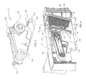
- FIG. 2 depicts a bottom perspective view of the table saw of FIG. 1 with the housing removed showing a movable carriage mounted on a pivoting frame beneath the work-piece support surface;
- FIG. 3 depicts a perspective view of the swing arm assembly of the table saw of FIG. 1 ;
- FIG. 4 depicts a partial perspective cross-sectional view of the swing arm assembly of FIG. 3 ;
- FIG. 5A depicts a perspective view of the mechanical fuse of FIG. 2 ;
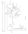
- FIG. 5B depicts a side view the swing arm assembly of the table saw supported by a mechanical fuse and including a shock absorber;
- FIG. 5C depicts a side view of the swing arm assembly of the table saw including a pull-type of actuator
- FIG. 5D depicts a front view of the swing arm assembly of FIG. 5C ;
- FIG. 6 depicts a partial perspective view of the swing arm assembly and latch assembly of FIG. 1 after the solenoid has been actuated thereby breaking the mechanical fuse along a break plane perpendicular to the solenoid axis;
- FIG. 7 depicts a partial perspective view of the swing arm assembly and latch assembly of FIG. 1 after the swing arm assembly has cleared the latch hold allowing the latch hold to be biased into the swing path;
- FIG. 8 depicts a partial perspective view of the swing arm assembly and latch assembly of FIG. 1 after the swing arm assembly has rebounded off of the stop pad and has been captured by a latch hold ledge thereby keeping the shaping device below the surface of the work-piece support surface;
- FIG. 9 depicts a partial perspective view of the swing arm assembly and latch assembly of FIG. 1 after the swing arm assembly has rebounded off of the stop pad and has been captured by a secondary latch hold ledge thereby keeping the shaping device below the surface of the work-piece support surface;
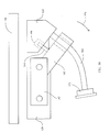
- FIG. 10 depicts a side view of the swing arm assembly of the table saw including a support rod and a cushion
- FIG. 11 depicts a cross sectional view of the actuator of the table saw
- FIG. 12 depicts a cross sectional view of the actuator of the table saw
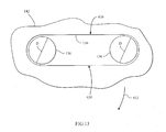
- FIG. 13 depicts a partial cross sectional view of the swing arm assembly of the table saw.
- FIG. 14 depicts a top plan view of the table saw of FIG. 1 .
- the table saw 100 includes a base housing 102 and a work-piece support surface 104.
- a splitter 106 is positioned adjacent to a blade 108 which extends from within the base housing 102 to above the work-piece support surface 104.
- a blade guard (not shown) may be attached to the splitter 106.
- An angle indicator 110 indicates the angle of the blade 108 with respect to the work-piece support surface 104.
- a bevel adjust turn-wheel 112 may be used to establish the angle of the blade 108 with respect to the work-piece support surface 104 by pivoting a frame 114 (shown in FIG. 2 ) within the base housing 102.
- a motor 116 which is powered through a switch 118 located on the base housing 102, is supported by a carriage assembly 120.
- the carriage assembly 120 and a stop pad 122 are supported by the frame 114.
- the carriage assembly 120 includes a carriage 124 to which the motor 116 is mounted and two guiderails 126/128.
- the position of the carriage 124 along the guiderails 126/128 is controlled by a blade height turn-wheel 130 through a gearing assembly 132 and a height adjustment rod 134.
- the carriage 124 fixedly supports a latch assembly 140 and pivotably supports a swing arm assembly 142.
- the swing arm assembly 142 is pivotally coupled to the carriage 124 for movement between a fused position (see FIG. 4A ) and a de-fused position (see FIG. 7 ).
- the swing arm assembly 142 includes a housing 144, which encloses a power wheel 150 that is driven by a power shaft 152.
- the power shaft 152 may be directly driven by the motor 116 or by a reduction gear.
- a belt 154 transfers rotational movement from the power wheel 150 to a blade wheel 156.
- a nut 158 is used to affix the blade 108 (not shown in FIGs. 3 and 4 for purpose of clarity) to the blade wheel 156.
- a tensioner 160 maintains the belt 154 at a desired tension.
- the swing arm assembly 142 may also include a strike plate 146 and a rebound plate 148 mounted on the housing 144.
- a latch hold 170 which is part of the latch assembly 140 includes three rebound ledges 174, 176, and 178 (see FIG. 4 ).
- the latch assembly 140 further includes a base 180 and an actuator 182 with an actuator pin 184.
- Two springs 186 and 188 are positioned between the base 180 and the latch hold 170 which is mounted by a pivot 190 to the carriage 124.
- a mechanical fuse 500 also shown in FIG. 5A , includes a base 502 coupled with the swing arm assembly 142 and a head 504 coupled to the base 180.
- the mechanical fuse includes a neck 506 which extends between the base 502 and the head 504.
- the mechanical fuse 500 may be monolithic.
- the base 502, neck 506, and head 504 may be formed from different compounds or materials, which are fused, coupled, or connected together.
- the mechanical fuse 500 is made from materials which are not affected by dust, lubrication, or corrosion.
- a mechanical fuse may be provided in the form of a shear pin. In such embodiments, the shear pin is aligned with a shear plane that is substantially parallel to the plane in which the swing arm assembly 142 pivots.
- the mechanical fuse 500 further includes features and elements for aligning the fuse 500 with the swing arm assembly 142 and the carriage 124.
- the mechanical fuse 500 includes a recess 508, which in this embodiment extends completely through the base 510 ( FIG. 4D ) for accepting a detent, such as a ball detent 510 ( FIG. 3 ), located in the swing arm assembly 142.
- a slot 512 is provided on the head 504 of the mechanical fuse 500. The slot 512 is configured to accept a fastener 514 (see FIG. 6 ).
- the fuse 500 includes contact portions 516 and 518 and gripping portions 520 and 522.
- the contact portions 516 and 518 are configured to contact guide portions 524 and 526, seen most clearly in FIG. 6 .
- the mechanical fuse is mounted by grasping the gripping portions 520 and 522 and placing the head 504 between the guide portions 524 and 526. Contact between the contact portions 516 and 518 and gripping portions 520 and 522 aligns the slot 512 with a mounting feature (not shown) in the base 180 such that the fastener 514 can be inserted through the slot 512 and coupled to the base 180. The mechanical fuse is then pulled downwardly until the fastener 514 contacts the upper end of the slot 512 at which point the recess 508 is positioned to receive the detent 510. Accordingly, the mechanical fuse 500 and the swing arm assembly 142 are both precisely aligned with the base 180.
- the actuator 182 is configured to generate a force sufficient to break the mechanical fuse 500 and to force the swing arm assembly 142 into the de-fused position. As shown in FIG. 5B , the actuator 182 is positioned within the base 180; however, in some embodiments the actuator 182 may be coupled to the swing arm assembly 142 or the frame 114.
- the actuator 182 includes a pin 182, which is movable along a pin axis 544, as shown in FIG. 4E .
- the pin axis 544 is approximately perpendicular to a break plane 548 of the mechanical fuse 500.
- the actuator 182 In response to being activated by a controller (not illustrated) the actuator 182 is configured move the pin 184 along the pin axis 544 to break the mechanical fuse 500 along the break plane 548.
- the mechanical fuse 500 may be positioned adjacent to the actuator 504.
- the mechanical fuse 500 maintains the swing arm assembly 142 of the table saw 100 in a fused position by coupling the swing arm assembly 142 to the latch hold base 180.
- the mechanical fuse 500 is configured to maintain the position of the swing arm assembly 142 under normal operational loads of the table saw 100.
- the springs 188 and 186 are under compression and exert a bias on the latch hold 170 about the pivot 190 in a clockwise direction as viewed in FIG. 4 .
- the blade wheel 156 is positioned sufficiently close to the work-piece support surface 104 that the blade 108 extends above the work-piece support surface 104 as shown in FIG. 1 .
- a user operates the bevel adjust turn wheel 112 to pivot the frame 114 with respect to the work-piece support surface 104 to establish a desired angle between the blade 108 and the work-piece support surface 104.
- the user further operates the blade height adjustment turn-wheel 130 to move the carriage 124 along the guiderails 126/128 to establish a desired height of the blade 108 above the work-piece support surface 104.
- the table saw 100 includes a sensing and control circuit (not shown) which activates the actuator 182 in response to a sensed condition. Any desired sensing and control circuit may be used for this purpose.
- One acceptable sensing and control circuit is described in U.S. Patent No. 6,922,153 , the entire contents of which are herein incorporated by reference.
- the safety detection and protection system described in the '153 patent senses an unsafe condition and provides a control signal which, in the table saw 100, is used to actuate the actuator 182.
- the actuator 182 drives the actuator pin 184 outwardly from the actuator 182.
- the swing arm assembly 142 is maintained in a fused position as shown in FIG. 2
- the strike plate 146 is aligned with the actuator 182.
- the actuator pin 184 contacts the swing arm assembly 142 and pivots the swing arm assembly 142 in a direction, which applies a force upon the mechanical fuse 500.
- the mechanical fuse 500 is configured to separate at a predetermined location under a predetermined amount of force along the break plane 548. As shown in FIG. 5B the mechanical fuse 500 is configured to separate at the neck 516, which is the portion of the mechanical fuse 500 at which stress is concentrated. Thus, once the applied force exceeds a tensile strength of the fuse 500, the fuse 500 separates into at least two pieces.
- the swing arm assembly 142 pivots about the power shaft 152 in the direction of the arrow 200 of FIG. 6 such that the blade wheel 156 moves away from the work-piece support surface 104 through the position shown in FIG. 6 to the position shown in FIG. 7 . Accordingly, the blade 108 is pulled by the swing arm assembly 142 in a direction away from the work-piece support surface 104.
- the actuator 504 may be configured to pivot the swing arm assembly 142 with a "pulling" force instead of a "pushing" force.
- an actuator 504 is mounted between a forked section 552 of the swing arm assembly 142.
- an arm 556 moves downwardly to pull the swing arm assembly 142 to the de-fused position.
- the rebound plate 148 of the swing arm assembly 142 rotates below the rebound ledge 178 of the latch hold 170.
- rotation of the latch hold 170 about the pivot 190 is no longer restrained by the swing arm assembly 142.
- the springs 186 and 188 cause the latch hold 170 to rotate into a position whereat the rebound ledge 178 is located in the swing path of the swing arm 142, that is, the path along which the swing arm 142 moves, as shown in FIG .7 .
- FIG. 7 further shows the swing arm assembly 142 rotated to a position whereat the swing arm assembly 142 contacts the stop pad 122. Accordingly, further rotation of the swing arm assembly 142 in the direction of the arrow 200 of FIG. 6 is impeded by the stop pad 122. At this position, the blade 108 is completely located below the work-piece support surface 104. Therefore, an operator above the work-piece support surface 104 cannot be injured by the blade 108.
- the stop pad 122 is made with microcellular polyurethane elastomer (MPE).
- MPEs form a material with numerous randomly oriented air chambers. Some of the air chambers are closed and some are linked. Additionally, the linked air chambers have varying degrees of communication between the chambers and the orientation of the linked chambers varies. Accordingly, when the MPE structure is compressed, air in the chambers is compressed. As the air is compressed, some of the air remains within various chambers, some of the air migrates between other chambers and some of the air is expelled from the structure.
- MPE microcellular polyurethane elastomer
- MH 24-65 commercially available from Elastogran GmbH under the trade name CELLASTO®.
- a foam material such as "memory foam" may be used.
- the swing arm assembly 142 Prior to impacting the stop pad 122, however, the swing arm assembly 142 may be moving with sufficient force to cause the swing arm assembly to rebound off of the stop pad 122. In such a circumstance, the swing arm assembly 142 will rotate about the power shaft 152 in a counterclockwise direction. Thus, the blade 108 moves toward the work-piece support surface 104. Movement of the blade 108 above the work-piece support surface 104, however, is inhibited by the latch hold 170.
- the spring constants for the springs 186 and 188 are thus selected to ensure that the latch hold 170 is positioned within the swing path of the swing arm assembly 142 before the swing arm assembly 142 travels from the latched position downwardly into contact with the stop pad 122 and then upwardly to a position whereat the blade 108 is above the work-piece support surface 104.
- the time available for moving the latch hold 170 into the swing path can be increased by moving the stop pad 122 further away from the work-piece support surface 104 along the swing path.
- Such modification increases the overall height of the frame 114, particularly for embodiments with variable blade height.
- the increased material for the frame 114 results in increased weight. Increased size and weight are generally not desired for movable power tools.
- positioning the stop pad 122 closer to the work-piece support surface 104 along the swing path reduces the height of the frame 114 and the resultant weight of the table saw 100.
- the distance between the swing arm assembly 142 in the latched position and the stop pad 122 is such that the swing arm assembly 142 contacts the stop pad 122 before the rebound plate 148 rotates beneath the rebound ledge 178.
- the rebound ledges 174 and 176 are provided at locations above the rebound ledge 178 to contact the rebound plate 148 when the swing arm assembly 142 is actuated with the carriage 124 positioned closer to the stop pad 122 as depicted in FIG. 9 .
- rebound ledges 174 and 176 may be provided as safety measures in the event the latch hold 170 does not move with the designed speed.
- the angle and length of the stop pad 122 are selected in the embodiment of FIG. 2 to o censure that the swing arm assembly 142 contacts the stop pad 122 at the foot 192 (see FIG. 3 ) regardless of the initial height of the carriage 124.
- the foot 192 receives the force of the impact when the swing arm assembly 142 contacts the stop pad 122.
- lighter materials may be used in other areas of the swing arm assembly 142 to minimize weight of the table saw 100.
- the table saw 100 may include a damper, dashpot, or shock absorber 560 to dissipate the energy of the swing arm assembly 142 as it pivots to the de-fused position.
- the shock absorber 560 contacts a striker plate 564 to dissipate the kinetic energy of the swing arm assembly 142.
- the shock absorber 560 prevents the swing arm assembly 142 from rebounding to the latched position.
- the shock absorber 560 may be a hydraulic shock absorber having a piston 562, which is moved into a body 566 of the shock absorber 560 upon contacting the striker plate 564.
- a fluid in the body 566 is heated, compressed, or expelled to dissipate the kinetic energy.
- the striker plate 564 is coupled to the carriage 124; however, the striker plate 564 may also be coupled to the frame 114.
- the table saw 100 may include a support rod 568 and a cushion 572 to dissipate the energy of the swing arm assembly 142 as it pivots to the delatched position.
- the support rod 568 has a curvature, which matches approximately the path taken by the swing arm assembly 142 as it pivots to the de-fused position (see direction 570 of FIG. 10 ).
- the cushion 572 is coupled to the end of the support rod 568, and is configured to dissipate the kinetic energy of the swing arm assembly 142. Because the support rod 568 is coupled to the carriage 124 the position of the cushion 572, remains fixed relative the position of the blade 108.
- the actuator 504 is configured to reduce the shock imparted upon the table saw 100 during activation of the actuator 504.
- the actuator 504 in one embodiment is a pyrotechnic actuator, which includes a housing 576, a charge 580, and piston 584 connected to the pin 540. Ignition of the charge 580 generates a large pressure within a chamber 588 in the housing 576. The pressure is imparted upon the piston 584 and results in the pin 540 moving at a very high rate of acceleration. Accordingly, the pressure results in a very high peak transient load in the structure of the table saw 100.
- the table saw 100 includes a robust frame 114 and portions of the swing arm assembly 142 are hardened. By reducing the transient loads, however, the robustness of the frame 114 and the strength of the materials in the swing arm 142 may be reduced without impacting the dynamic performance of the actuator 504 or slowing movement of the blade 108 to a position below the surface of the work-piece support surface 104.
- one approach to reducing the transient load generated by the actuator 504 is to include a relief valve 592 fluidly coupled to the chamber 588.
- the relief valve 592 reduces the peak amount of pressure imparted upon the piston 584 in response to the ignition of the charge 580.
- FIG. 11 Another approach to reducing the peak transient load is illustrated in FIG. 11 .
- a divider 596 having an orifice 600 may be included in the chamber 588 to reduce the peak pressure imparted upon the piston 584 following ignition of the charge 580.
- the housing 576 is surrounded by a shock absorbing mounting 604 and a casing 608 to reduce further the peak transient load.
- the housing 576 is configured for movement relative the casing 608.
- the swing arm assembly 142 of FIG. 13 is configured to reduce the shock imparted upon the belt 154 in response to the sudden pivotal motion of the swing arm assembly 142 following activation of the actuator 504.
- the actuator 504 pivots the swing arm assembly 142 in response to a sensed condition
- the swing arm assembly 142 moves through a substantial angular range in a fraction of a second, as represented by direction 612 of FIG. 13 .
- the rotation of the swing arm assembly 142 causes the belt 152 to become tighter on an upper side 616 and looser on a lower side 620.
- the force exerted upon the upper side 616 is not equal to the force exerted on the lower side 620 and the belt 154 may be damaged. If, however, as illustrated in FIG. 13 , the power wheel 150 and the blade wheel 156 have the same diameter D, then the force on the upper side 616 of the belt 154 is equal to the force on the lower side 620 of the belt 154, thereby cancelling the damaging effects. In some embodiments the diameter of the power wheel 150 may be within 15% of the diameter of blade wheel 156 without damaging the belt 152.
- the swing arm assembly 142 is reset by moving the latch hold 170 out of the swing path. This is effected by compressing the springs 188 and 186. The swing arm assembly 142 may then be rotated in a counterclockwise direction about the output shaft 152 until the rebound plate 148 is adjacent to the upper surface of the latch hold 170. The latch hold 170 is then released and the springs 188 and 186 bias the latch hold 170 about the pivot 190 into contact with the lip 164 of the swing arm assembly 142 which restricts rotation of the latch hold 170. Additionally, a new mechanical fuse 500 is positioned in the manner described above.
- the table saw 100 may include an access door 624 for resetting the swing arm assembly 142.
- the access door 624 is formed in the work-piece support surface 104. When removed from the work-piece support surface 104, the access door 624 reveals an opening in the work-piece support surface 104 through which the swing arm assembly 142 is accessed.
- the access door 624 has a dimension at least fifty percent or more of the diameter of the saw blade 108.
- the table saw 100 thus actively monitors for an unsafe condition and initiates mitigation action automatically in the event an unsafe condition is sensed. Additionally, movement and subsequent stopping of the swing arm assembly 172 is accomplished without requiring physical contact with the blade 108. Accordingly, the blade 108 is not damaged by the mitigation action.
- the mitigation system of the table saw 100 may be used with other shaping devices such as sanding wheels, blades with varying dado blades, and molding head cutters, without requiring any modification to the mitigation system. Additionally, because the moving components of the mitigation system can be mounted on the frame 114, the mitigation system can be used with any desired blade height or bevel angle.
- the mitigation system discussed with respect to the table saw 100 can be implemented using very light materials, and is thus amenable to incorporation into a variety of power tools including bench top saws and portable saws.
- the components which are subjected to increased stress within the mitigation system such as the solenoid pin 184, the latch hold 170, the rebound plate 148, and the strike plate 146, can be made of more durable materials including metals to withstand the impacts and stresses of activating the mitigation system.
- Other components, including the housings may be fabricated from more lightweight materials to minimize the weight of the power tool.
- Embodiment 9 A table saw comprising:
- Embodiment 10 The table saw of embodiment 9, further comprising:
- Embodiment 11 The table saw of embodiment 10, wherein the mechanical fuse comprises:
- Embodiment 12 A power tool, comprising:
- Embodiment 13 The power tool of embodiment 12, wherein:
- Embodiment 14 The power tool of embodiment 13, wherein the mechanical fuse comprises:
- Embodiment 15 The power tool of embodiment 14, wherein the mechanical fuse further comprises:
- Embodiment 16 The power tool of embodiment 14, wherein:
- Embodiment 17 The power tool of embodiment 14, wherein the second connection portion comprises a base portion extending in a first plane and a pair of opposing flanges extending out of the first plane.
- Embodiment 18 The power tool of embodiment 12, wherein the mechanical fuse is positioned adjacent to the actuating device.
- Embodiment 19 The power tool of embodiment 12, wherein the mechanical fuse comprises a shear pin.
Landscapes
- Life Sciences & Earth Sciences (AREA)
- Engineering & Computer Science (AREA)
- Mechanical Engineering (AREA)
- Wood Science & Technology (AREA)
- Forests & Forestry (AREA)
- Sawing (AREA)
Applications Claiming Priority (1)
| Application Number | Priority Date | Filing Date | Title |
|---|---|---|---|
| US12/548,201 US8210076B2 (en) | 2009-08-26 | 2009-08-26 | Table saw with mechanical fuse |
Publications (3)
| Publication Number | Publication Date |
|---|---|
| EP2289680A2 true EP2289680A2 (fr) | 2011-03-02 |
| EP2289680A3 EP2289680A3 (fr) | 2014-03-12 |
| EP2289680B1 EP2289680B1 (fr) | 2016-03-23 |
Family
ID=43242523
Family Applications (1)
| Application Number | Title | Priority Date | Filing Date |
|---|---|---|---|
| EP10174042.1A Not-in-force EP2289680B1 (fr) | 2009-08-26 | 2010-08-25 | Scie circulaire avec fusible mécanique |
Country Status (4)
| Country | Link |
|---|---|
| US (2) | US8210076B2 (fr) |
| EP (1) | EP2289680B1 (fr) |
| CN (1) | CN102000877B (fr) |
| TW (1) | TWI517955B (fr) |
Families Citing this family (26)
| Publication number | Priority date | Publication date | Assignee | Title |
|---|---|---|---|---|
| US8844415B2 (en) * | 2011-12-23 | 2014-09-30 | Robert Bosch Gmbh | Table saw dust cover |
| WO2014152285A1 (fr) * | 2013-03-15 | 2014-09-25 | Robert Bosch Gmbh | Piston pour un vérin pneumatique comprenant une structure de concentration de contraintes |
| CN107427942B (zh) * | 2014-12-15 | 2019-11-05 | 罗伯特·博世有限公司 | 用于台锯的摆臂的棘轮和释放机构 |
| US9868167B2 (en) * | 2015-03-12 | 2018-01-16 | Robert Bosch Tool Corporation | Power tool with drop arm orbit bracket |
| TWI729980B (zh) * | 2015-03-12 | 2021-06-11 | 德商羅伯特博斯奇股份有限公司 | 具有心軸鎖定件的動力工具及相關定位方法 |
| US10213853B2 (en) * | 2015-03-12 | 2019-02-26 | Robert Bosch Tool Corporation | Power tool drop arm with offset ribbing |
| US10758989B2 (en) | 2015-03-12 | 2020-09-01 | Robert Bosch Tool Corporation | System and method for sensing cable fault detection in a saw |
| US9969015B2 (en) | 2015-03-12 | 2018-05-15 | Robert Bosch Tool Corporation | Power tool with protected coupling plate |
| US10821529B2 (en) | 2015-03-12 | 2020-11-03 | Robert Bosch Tool Corporation | Power tool with improved belt tensioning |
| US10427227B2 (en) | 2015-03-12 | 2019-10-01 | Robert Bosch Tool Corporation | Drop arm reset method |
| US10071432B2 (en) | 2015-03-12 | 2018-09-11 | Robert Bosch Tool Corporation | Power tool with arbor lock |
| US9687922B2 (en) | 2015-03-12 | 2017-06-27 | Robert Bosch Tool Corporation | Power tool with cammed throat plate |
| US10105863B2 (en) | 2015-03-12 | 2018-10-23 | Robert Bosch Tool Corporation | System and method for object and operator profiling in an object detection system in a saw |
| US10369642B2 (en) | 2015-03-12 | 2019-08-06 | Robert Bosch Tool Corporation | Power tool with protected circuit board orientation |
| US10099399B2 (en) | 2015-03-12 | 2018-10-16 | Robert Bosch Tool Corporation | Object proximity detection in a saw |
| US10189098B2 (en) | 2015-03-12 | 2019-01-29 | Robert Bosch Tool Corporation | Diagnostic and maintenance operation for a saw |
| US10786854B2 (en) * | 2015-03-12 | 2020-09-29 | Robert Bosch Tool Corporation | Table saw with electrically isolated arbor shaft |
| US9914239B2 (en) | 2015-03-12 | 2018-03-13 | Robert Bosch Tool Corporation | User interface system in a table saw |
| US10322522B2 (en) | 2015-03-12 | 2019-06-18 | Robert Bosch Tool Corporation | Electrical configuration for object detection system in a saw |
| US9849527B2 (en) * | 2015-03-12 | 2017-12-26 | Robert Bosch Tool Corporation | Power tool with lightweight actuator housing |
| US10493543B2 (en) * | 2015-03-12 | 2019-12-03 | Robert Bosch Tool Corporation | Power tool motor with reduced electrical noise |
| US9868166B2 (en) | 2015-03-12 | 2018-01-16 | Robert Bosch Tool Corporation | Power tool with pyrotechnic lockout |
| US10799964B2 (en) * | 2015-03-12 | 2020-10-13 | Robert Bosch Tool Corporation | Table saw with pulley alignment mechanism |
| US10413979B2 (en) * | 2016-08-05 | 2019-09-17 | Robert Bosch Tool Corporation | Table saw with cutting blade safety feature |
| CN106735541A (zh) * | 2016-12-23 | 2017-05-31 | 济南华信自动化工程有限公司 | 一种多功能下料锯床锯切装置 |
| CN109664384A (zh) * | 2019-02-01 | 2019-04-23 | 安徽理工大学 | 一种安全台锯 |
Citations (1)
| Publication number | Priority date | Publication date | Assignee | Title |
|---|---|---|---|---|
| US6922153B2 (en) | 2003-05-13 | 2005-07-26 | Credo Technology Corporation | Safety detection and protection system for power tools |
Family Cites Families (75)
| Publication number | Priority date | Publication date | Assignee | Title |
|---|---|---|---|---|
| US2505958A (en) | 1946-07-19 | 1950-05-02 | John O Grierson | Swinging power saw |
| US2652863A (en) | 1948-05-11 | 1953-09-22 | Edward E Grabinski | Power-driven table tool with portable vertical-shaft motor |
| US2719547A (en) | 1952-03-01 | 1955-10-04 | Gjerde Arne | Universally adjustable underbench saw |
| US2844173A (en) | 1954-09-13 | 1958-07-22 | King Seely Corp | Arbor saw with single handle control of tilt and elevation |
| US2903848A (en) | 1956-12-05 | 1959-09-15 | Republic Aviat Corp | Self-contained emergency fluid cylinder |
| US2937672A (en) | 1957-10-17 | 1960-05-24 | Gjerde Arne | Adjustable motor-driven saw |
| US2898893A (en) | 1958-04-11 | 1959-08-11 | Little Inc A | Impact tool |
| US3013592A (en) | 1959-03-23 | 1961-12-19 | Theodore G Ambrosio | Tilting table saw |
| US3036608A (en) | 1959-04-20 | 1962-05-29 | Weber Carl | Portable supporting and mounting device for power tools |
| US3320740A (en) | 1965-07-02 | 1967-05-23 | Walker Mfg Co | Press |
| US3344819A (en) | 1965-10-20 | 1967-10-03 | Donald H Benson | Table saw |
| US3715697A (en) * | 1971-05-24 | 1973-02-06 | Therm O Disc Inc | Thermal fuse |
| DE2361001C2 (de) | 1973-12-07 | 1986-05-07 | Hauni-Werke Körber & Co KG, 2050 Hamburg | Vorrichtung zum Abschneiden eines Stranges |
| DE2654521A1 (de) * | 1976-12-01 | 1978-06-08 | Mey Kg Maschf Mafell | Nagelvorrichtung |
| NO139405C (no) | 1977-04-01 | 1979-03-07 | Arne Gjerde | Motordrevet sag med sirkelblad. |
| US4336733A (en) | 1980-06-06 | 1982-06-29 | Macksoud Albert A | Rocking arm saw |
| DE3306841A1 (de) * | 1983-02-26 | 1984-08-30 | Mafell Maschinenfabrik Rudolf Mey GmbH & Co KG, 7238 Oberndorf | Verfahren zur bearbeitung eines werkstoffs oder werkstuecks mittels ultraschall und vorrichtung zur durchfuehrung des verfahrens |
| US5119555A (en) * | 1988-09-19 | 1992-06-09 | Tini Alloy Company | Non-explosive separation device |
| US4962685A (en) | 1988-10-27 | 1990-10-16 | Hagstrom Oscar E | Production table saw |
| GB9425390D0 (en) | 1994-12-12 | 1995-02-15 | Black & Decker Inc | A double bevel table saw |
| US5676319A (en) * | 1995-10-23 | 1997-10-14 | Stiggins; Kendy Lee | Garbage disposal system |
| US6536536B1 (en) * | 1999-04-29 | 2003-03-25 | Stephen F. Gass | Power tools |
| US6036608A (en) | 1999-05-07 | 2000-03-14 | Morris; John K. | Golf putting and chipping training apparatus |
| US6530303B1 (en) | 1999-06-10 | 2003-03-11 | Black & Decker Inc. | Table saw |
| US7509899B2 (en) * | 2000-08-14 | 2009-03-31 | Sd3, Llc | Retraction system for use in power equipment |
| US7827890B2 (en) | 2004-01-29 | 2010-11-09 | Sd3, Llc | Table saws with safety systems and systems to mount and index attachments |
| US20050041359A1 (en) * | 2003-08-20 | 2005-02-24 | Gass Stephen F. | Motion detecting system for use in a safety system for power equipment |
| US7290472B2 (en) * | 2002-01-14 | 2007-11-06 | Sd3, Llc | Miter saw with improved safety system |
| US6945149B2 (en) * | 2001-07-25 | 2005-09-20 | Sd3, Llc | Actuators for use in fast-acting safety systems |
| US6877410B2 (en) * | 2000-09-29 | 2005-04-12 | Sd3, Llc | Miter saw with improved safety system |
| US7077039B2 (en) * | 2001-11-13 | 2006-07-18 | Sd3, Llc | Detection system for power equipment |
| US7137326B2 (en) * | 2000-08-14 | 2006-11-21 | Sd3, Llc | Translation stop for use in power equipment |
| US6945148B2 (en) * | 2000-09-29 | 2005-09-20 | Sd3, Llc | Miter saw with improved safety system |
| US7024975B2 (en) * | 2000-08-14 | 2006-04-11 | Sd3, Llc | Brake mechanism for power equipment |
| US7055417B1 (en) * | 1999-10-01 | 2006-06-06 | Sd3, Llc | Safety system for power equipment |
| US7100483B2 (en) * | 2000-08-14 | 2006-09-05 | Sd3, Llc | Firing subsystem for use in a fast-acting safety system |
| US7171879B2 (en) * | 2001-07-02 | 2007-02-06 | Sd3, Llc | Discrete proximity detection system |
| US7308843B2 (en) * | 2000-08-14 | 2007-12-18 | Sd3, Llc | Spring-biased brake mechanism for power equipment |
| US6857345B2 (en) * | 2000-08-14 | 2005-02-22 | Sd3, Llc | Brake positioning system |
| US7472634B2 (en) * | 2003-08-20 | 2009-01-06 | Sd3, Llc | Woodworking machines with overmolded arbors |
| US7600455B2 (en) * | 2000-08-14 | 2009-10-13 | Sd3, Llc | Logic control for fast-acting safety system |
| US7481140B2 (en) * | 2005-04-15 | 2009-01-27 | Sd3, Llc | Detection systems for power equipment |
| US7000514B2 (en) * | 2001-07-27 | 2006-02-21 | Sd3, Llc | Safety systems for band saws |
| US7231856B2 (en) * | 2001-06-13 | 2007-06-19 | Sd3, Llc | Apparatus and method for detecting dangerous conditions in power equipment |
| US7197969B2 (en) * | 2001-09-24 | 2007-04-03 | Sd3, Llc | Logic control with test mode for fast-acting safety system |
| US6880440B2 (en) * | 2000-09-29 | 2005-04-19 | Sd3, Llc | Miter saw with improved safety system |
| US7377199B2 (en) * | 2000-09-29 | 2008-05-27 | Sd3, Llc | Contact detection system for power equipment |
| US20030037651A1 (en) * | 2001-08-13 | 2003-02-27 | Gass Stephen F. | Safety systems for power equipment |
| US7350444B2 (en) * | 2000-08-14 | 2008-04-01 | Sd3, Llc | Table saw with improved safety system |
| US8065943B2 (en) | 2000-09-18 | 2011-11-29 | Sd3, Llc | Translation stop for use in power equipment |
| US7225712B2 (en) * | 2000-08-14 | 2007-06-05 | Sd3, Llc | Motion detecting system for use in a safety system for power equipment |
| US7210383B2 (en) * | 2000-08-14 | 2007-05-01 | Sd3, Llc | Detection system for power equipment |
| US7098800B2 (en) * | 2003-03-05 | 2006-08-29 | Sd3, Llc | Retraction system and motor position for use with safety systems for power equipment |
| US6957601B2 (en) * | 2000-08-14 | 2005-10-25 | Sd3, Llc | Translation stop for use in power equipment |
| US6994004B2 (en) * | 2000-09-29 | 2006-02-07 | Sd3, Llc | Table saw with improved safety system |
| US7536238B2 (en) * | 2003-12-31 | 2009-05-19 | Sd3, Llc | Detection systems for power equipment |
| US7350445B2 (en) * | 2003-08-20 | 2008-04-01 | Sd3, Llc | Brake cartridge for power equipment |
| US7353737B2 (en) * | 2001-08-13 | 2008-04-08 | Sd3, Llc | Miter saw with improved safety system |
| US7284467B2 (en) * | 2000-08-14 | 2007-10-23 | Sd3, Llc | Apparatus and method for detecting dangerous conditions in power equipment |
| US6920814B2 (en) * | 2000-08-14 | 2005-07-26 | Sd3, Llc | Cutting tool safety system |
| US8061245B2 (en) * | 2000-09-29 | 2011-11-22 | Sd3, Llc | Safety methods for use in power equipment |
| DE20007037U1 (de) | 2000-04-17 | 2000-07-20 | Mafell AG, 78727 Oberndorf | Tischkreissäge |
| WO2002014028A2 (fr) | 2000-08-15 | 2002-02-21 | Fisher Power Wave Limited | Dispositifs a came ameliores |
| US6826988B2 (en) * | 2000-09-29 | 2004-12-07 | Sd3, Llc | Miter saw with improved safety system |
| US6813983B2 (en) * | 2000-09-29 | 2004-11-09 | Sd3, Llc | Power saw with improved safety system |
| EP1432553B1 (fr) * | 2001-07-11 | 2010-11-24 | Black & Decker Inc. | Mecanismes de securite pour outil electrique |
| US7241315B2 (en) * | 2001-07-23 | 2007-07-10 | Robert Evans | Femoral head resurfacing apparatus and methods |
| US7698975B2 (en) * | 2003-01-31 | 2010-04-20 | Techtronic Power Tools Technology Limited | Table saw with cutting tool retraction system |
| DE10329826A1 (de) * | 2003-06-27 | 2005-01-13 | Festool Gmbh | Schleifteller |
| DE202004012468U1 (de) | 2003-11-21 | 2004-11-04 | Festool Gmbh | Tischkreissäge |
| EP1563969B1 (fr) * | 2004-02-13 | 2007-03-07 | Festool GmbH | Dispositif d'aspiration des poussières pour une toupie |
| US7628101B1 (en) * | 2006-03-13 | 2009-12-08 | Power Tool Institute | Pyrotechnic drop mechanism for power tools |
| FR2883606B1 (fr) * | 2005-03-24 | 2010-03-19 | Snpe Materiaux Energetiques | Actionneur pyrotechnique muni d'un organe regulateur de pression |
| US20070074613A1 (en) | 2005-10-04 | 2007-04-05 | Ben Yu | Worktable having adjustable shield |
| US7721633B2 (en) | 2006-10-24 | 2010-05-25 | Gaw Stanley E | Dual bevel table and slide miter saw |
-
2009
- 2009-08-26 US US12/548,201 patent/US8210076B2/en not_active Expired - Fee Related
-
2010
- 2010-08-24 TW TW099128204A patent/TWI517955B/zh not_active IP Right Cessation
- 2010-08-25 EP EP10174042.1A patent/EP2289680B1/fr not_active Not-in-force
- 2010-08-26 CN CN201010510667.8A patent/CN102000877B/zh not_active Expired - Fee Related
-
2012
- 2012-06-29 US US13/538,422 patent/US8578825B2/en not_active Expired - Fee Related
Patent Citations (1)
| Publication number | Priority date | Publication date | Assignee | Title |
|---|---|---|---|---|
| US6922153B2 (en) | 2003-05-13 | 2005-07-26 | Credo Technology Corporation | Safety detection and protection system for power tools |
Also Published As
| Publication number | Publication date |
|---|---|
| US20120325065A1 (en) | 2012-12-27 |
| EP2289680B1 (fr) | 2016-03-23 |
| CN102000877B (zh) | 2015-06-03 |
| TWI517955B (zh) | 2016-01-21 |
| TW201111133A (en) | 2011-04-01 |
| CN102000877A (zh) | 2011-04-06 |
| US8210076B2 (en) | 2012-07-03 |
| US8578825B2 (en) | 2013-11-12 |
| US20110048192A1 (en) | 2011-03-03 |
| EP2289680A3 (fr) | 2014-03-12 |
Similar Documents
| Publication | Publication Date | Title |
|---|---|---|
| US8210076B2 (en) | Table saw with mechanical fuse | |
| EP2289681B1 (fr) | Scie circulaire avec un système de retrait d'outil | |
| EP2289679B1 (fr) | Scie circulaire avec mécanisme de verrouillage positif | |
| US8186258B2 (en) | Table saw with actuator reset mechanism | |
| US8250957B2 (en) | Table saw with linkage drop system | |
| US8316748B2 (en) | Table saw with alignment plate | |
| US8651001B2 (en) | Table saw with reset mechanism | |
| US8291801B2 (en) | Table saw with ratchet mechanism | |
| US8245612B2 (en) | Table saw with swing arm support | |
| US8286537B2 (en) | Table saw with pressure operated actuator | |
| US9079258B2 (en) | Table saw with belt stop | |
| US10076796B2 (en) | Table saw with dust shield | |
| US9969013B2 (en) | Table saw with actuator module | |
| EP3233400B1 (fr) | Mécanisme à cliquet et de libération pour bras oscillant de scie circulaire à table |
Legal Events
| Date | Code | Title | Description |
|---|---|---|---|
| PUAI | Public reference made under article 153(3) epc to a published international application that has entered the european phase |
Free format text: ORIGINAL CODE: 0009012 |
|
| AK | Designated contracting states |
Kind code of ref document: A2 Designated state(s): AL AT BE BG CH CY CZ DE DK EE ES FI FR GB GR HR HU IE IS IT LI LT LU LV MC MK MT NL NO PL PT RO SE SI SK SM TR |
|
| AX | Request for extension of the european patent |
Extension state: BA ME RS |
|
| PUAL | Search report despatched |
Free format text: ORIGINAL CODE: 0009013 |
|
| AK | Designated contracting states |
Kind code of ref document: A3 Designated state(s): AL AT BE BG CH CY CZ DE DK EE ES FI FR GB GR HR HU IE IS IT LI LT LU LV MC MK MT NL NO PL PT RO SE SI SK SM TR |
|
| AX | Request for extension of the european patent |
Extension state: BA ME RS |
|
| RIC1 | Information provided on ipc code assigned before grant |
Ipc: B27G 19/02 20060101AFI20140205BHEP |
|
| 17P | Request for examination filed |
Effective date: 20140912 |
|
| RBV | Designated contracting states (corrected) |
Designated state(s): AL AT BE BG CH CY CZ DE DK EE ES FI FR GB GR HR HU IE IS IT LI LT LU LV MC MK MT NL NO PL PT RO SE SI SK SM TR |
|
| 17Q | First examination report despatched |
Effective date: 20150122 |
|
| GRAP | Despatch of communication of intention to grant a patent |
Free format text: ORIGINAL CODE: EPIDOSNIGR1 |
|
| INTG | Intention to grant announced |
Effective date: 20151007 |
|
| GRAS | Grant fee paid |
Free format text: ORIGINAL CODE: EPIDOSNIGR3 |
|
| GRAA | (expected) grant |
Free format text: ORIGINAL CODE: 0009210 |
|
| AK | Designated contracting states |
Kind code of ref document: B1 Designated state(s): AL AT BE BG CH CY CZ DE DK EE ES FI FR GB GR HR HU IE IS IT LI LT LU LV MC MK MT NL NO PL PT RO SE SI SK SM TR |
|
| REG | Reference to a national code |
Ref country code: GB Ref legal event code: FG4D |
|
| REG | Reference to a national code |
Ref country code: CH Ref legal event code: EP |
|
| REG | Reference to a national code |
Ref country code: AT Ref legal event code: REF Ref document number: 782666 Country of ref document: AT Kind code of ref document: T Effective date: 20160415 |
|
| REG | Reference to a national code |
Ref country code: IE Ref legal event code: FG4D |
|
| REG | Reference to a national code |
Ref country code: DE Ref legal event code: R096 Ref document number: 602010031361 Country of ref document: DE |
|
| REG | Reference to a national code |
Ref country code: LT Ref legal event code: MG4D |
|
| REG | Reference to a national code |
Ref country code: NL Ref legal event code: MP Effective date: 20160323 |
|
| PG25 | Lapsed in a contracting state [announced via postgrant information from national office to epo] |
Ref country code: FI Free format text: LAPSE BECAUSE OF FAILURE TO SUBMIT A TRANSLATION OF THE DESCRIPTION OR TO PAY THE FEE WITHIN THE PRESCRIBED TIME-LIMIT Effective date: 20160323 Ref country code: GR Free format text: LAPSE BECAUSE OF FAILURE TO SUBMIT A TRANSLATION OF THE DESCRIPTION OR TO PAY THE FEE WITHIN THE PRESCRIBED TIME-LIMIT Effective date: 20160624 Ref country code: NO Free format text: LAPSE BECAUSE OF FAILURE TO SUBMIT A TRANSLATION OF THE DESCRIPTION OR TO PAY THE FEE WITHIN THE PRESCRIBED TIME-LIMIT Effective date: 20160623 |
|
| REG | Reference to a national code |
Ref country code: AT Ref legal event code: MK05 Ref document number: 782666 Country of ref document: AT Kind code of ref document: T Effective date: 20160323 |
|
| PG25 | Lapsed in a contracting state [announced via postgrant information from national office to epo] |
Ref country code: NL Free format text: LAPSE BECAUSE OF FAILURE TO SUBMIT A TRANSLATION OF THE DESCRIPTION OR TO PAY THE FEE WITHIN THE PRESCRIBED TIME-LIMIT Effective date: 20160323 Ref country code: SE Free format text: LAPSE BECAUSE OF FAILURE TO SUBMIT A TRANSLATION OF THE DESCRIPTION OR TO PAY THE FEE WITHIN THE PRESCRIBED TIME-LIMIT Effective date: 20160323 Ref country code: LT Free format text: LAPSE BECAUSE OF FAILURE TO SUBMIT A TRANSLATION OF THE DESCRIPTION OR TO PAY THE FEE WITHIN THE PRESCRIBED TIME-LIMIT Effective date: 20160323 Ref country code: LV Free format text: LAPSE BECAUSE OF FAILURE TO SUBMIT A TRANSLATION OF THE DESCRIPTION OR TO PAY THE FEE WITHIN THE PRESCRIBED TIME-LIMIT Effective date: 20160323 |
|
| PG25 | Lapsed in a contracting state [announced via postgrant information from national office to epo] |
Ref country code: IS Free format text: LAPSE BECAUSE OF FAILURE TO SUBMIT A TRANSLATION OF THE DESCRIPTION OR TO PAY THE FEE WITHIN THE PRESCRIBED TIME-LIMIT Effective date: 20160723 Ref country code: EE Free format text: LAPSE BECAUSE OF FAILURE TO SUBMIT A TRANSLATION OF THE DESCRIPTION OR TO PAY THE FEE WITHIN THE PRESCRIBED TIME-LIMIT Effective date: 20160323 Ref country code: PL Free format text: LAPSE BECAUSE OF FAILURE TO SUBMIT A TRANSLATION OF THE DESCRIPTION OR TO PAY THE FEE WITHIN THE PRESCRIBED TIME-LIMIT Effective date: 20160323 |
|
| PG25 | Lapsed in a contracting state [announced via postgrant information from national office to epo] |
Ref country code: ES Free format text: LAPSE BECAUSE OF FAILURE TO SUBMIT A TRANSLATION OF THE DESCRIPTION OR TO PAY THE FEE WITHIN THE PRESCRIBED TIME-LIMIT Effective date: 20160323 Ref country code: SM Free format text: LAPSE BECAUSE OF FAILURE TO SUBMIT A TRANSLATION OF THE DESCRIPTION OR TO PAY THE FEE WITHIN THE PRESCRIBED TIME-LIMIT Effective date: 20160323 Ref country code: SK Free format text: LAPSE BECAUSE OF FAILURE TO SUBMIT A TRANSLATION OF THE DESCRIPTION OR TO PAY THE FEE WITHIN THE PRESCRIBED TIME-LIMIT Effective date: 20160323 Ref country code: AT Free format text: LAPSE BECAUSE OF FAILURE TO SUBMIT A TRANSLATION OF THE DESCRIPTION OR TO PAY THE FEE WITHIN THE PRESCRIBED TIME-LIMIT Effective date: 20160323 Ref country code: CZ Free format text: LAPSE BECAUSE OF FAILURE TO SUBMIT A TRANSLATION OF THE DESCRIPTION OR TO PAY THE FEE WITHIN THE PRESCRIBED TIME-LIMIT Effective date: 20160323 Ref country code: PT Free format text: LAPSE BECAUSE OF FAILURE TO SUBMIT A TRANSLATION OF THE DESCRIPTION OR TO PAY THE FEE WITHIN THE PRESCRIBED TIME-LIMIT Effective date: 20160725 Ref country code: RO Free format text: LAPSE BECAUSE OF FAILURE TO SUBMIT A TRANSLATION OF THE DESCRIPTION OR TO PAY THE FEE WITHIN THE PRESCRIBED TIME-LIMIT Effective date: 20160323 |
|
| PG25 | Lapsed in a contracting state [announced via postgrant information from national office to epo] |
Ref country code: IT Free format text: LAPSE BECAUSE OF FAILURE TO SUBMIT A TRANSLATION OF THE DESCRIPTION OR TO PAY THE FEE WITHIN THE PRESCRIBED TIME-LIMIT Effective date: 20160323 Ref country code: BE Free format text: LAPSE BECAUSE OF FAILURE TO SUBMIT A TRANSLATION OF THE DESCRIPTION OR TO PAY THE FEE WITHIN THE PRESCRIBED TIME-LIMIT Effective date: 20160323 |
|
| REG | Reference to a national code |
Ref country code: DE Ref legal event code: R097 Ref document number: 602010031361 Country of ref document: DE |
|
| PLBE | No opposition filed within time limit |
Free format text: ORIGINAL CODE: 0009261 |
|
| STAA | Information on the status of an ep patent application or granted ep patent |
Free format text: STATUS: NO OPPOSITION FILED WITHIN TIME LIMIT |
|
| PG25 | Lapsed in a contracting state [announced via postgrant information from national office to epo] |
Ref country code: DK Free format text: LAPSE BECAUSE OF FAILURE TO SUBMIT A TRANSLATION OF THE DESCRIPTION OR TO PAY THE FEE WITHIN THE PRESCRIBED TIME-LIMIT Effective date: 20160323 |
|
| PG25 | Lapsed in a contracting state [announced via postgrant information from national office to epo] |
Ref country code: BG Free format text: LAPSE BECAUSE OF FAILURE TO SUBMIT A TRANSLATION OF THE DESCRIPTION OR TO PAY THE FEE WITHIN THE PRESCRIBED TIME-LIMIT Effective date: 20160623 |
|
| 26N | No opposition filed |
Effective date: 20170102 |
|
| PG25 | Lapsed in a contracting state [announced via postgrant information from national office to epo] |
Ref country code: MC Free format text: LAPSE BECAUSE OF FAILURE TO SUBMIT A TRANSLATION OF THE DESCRIPTION OR TO PAY THE FEE WITHIN THE PRESCRIBED TIME-LIMIT Effective date: 20160323 |
|
| REG | Reference to a national code |
Ref country code: CH Ref legal event code: PL |
|
| GBPC | Gb: european patent ceased through non-payment of renewal fee |
Effective date: 20160825 |
|
| PG25 | Lapsed in a contracting state [announced via postgrant information from national office to epo] |
Ref country code: LI Free format text: LAPSE BECAUSE OF NON-PAYMENT OF DUE FEES Effective date: 20160831 Ref country code: CH Free format text: LAPSE BECAUSE OF NON-PAYMENT OF DUE FEES Effective date: 20160831 |
|
| REG | Reference to a national code |
Ref country code: FR Ref legal event code: ST Effective date: 20170428 |
|
| PG25 | Lapsed in a contracting state [announced via postgrant information from national office to epo] |
Ref country code: SI Free format text: LAPSE BECAUSE OF FAILURE TO SUBMIT A TRANSLATION OF THE DESCRIPTION OR TO PAY THE FEE WITHIN THE PRESCRIBED TIME-LIMIT Effective date: 20160323 |
|
| REG | Reference to a national code |
Ref country code: IE Ref legal event code: MM4A |
|
| PG25 | Lapsed in a contracting state [announced via postgrant information from national office to epo] |
Ref country code: GB Free format text: LAPSE BECAUSE OF NON-PAYMENT OF DUE FEES Effective date: 20160825 Ref country code: IE Free format text: LAPSE BECAUSE OF NON-PAYMENT OF DUE FEES Effective date: 20160825 Ref country code: FR Free format text: LAPSE BECAUSE OF NON-PAYMENT OF DUE FEES Effective date: 20160831 |
|
| PG25 | Lapsed in a contracting state [announced via postgrant information from national office to epo] |
Ref country code: LU Free format text: LAPSE BECAUSE OF NON-PAYMENT OF DUE FEES Effective date: 20160825 |
|
| PG25 | Lapsed in a contracting state [announced via postgrant information from national office to epo] |
Ref country code: CY Free format text: LAPSE BECAUSE OF FAILURE TO SUBMIT A TRANSLATION OF THE DESCRIPTION OR TO PAY THE FEE WITHIN THE PRESCRIBED TIME-LIMIT Effective date: 20160323 Ref country code: HU Free format text: LAPSE BECAUSE OF FAILURE TO SUBMIT A TRANSLATION OF THE DESCRIPTION OR TO PAY THE FEE WITHIN THE PRESCRIBED TIME-LIMIT; INVALID AB INITIO Effective date: 20100825 |
|
| PG25 | Lapsed in a contracting state [announced via postgrant information from national office to epo] |
Ref country code: TR Free format text: LAPSE BECAUSE OF FAILURE TO SUBMIT A TRANSLATION OF THE DESCRIPTION OR TO PAY THE FEE WITHIN THE PRESCRIBED TIME-LIMIT Effective date: 20160323 Ref country code: MK Free format text: LAPSE BECAUSE OF FAILURE TO SUBMIT A TRANSLATION OF THE DESCRIPTION OR TO PAY THE FEE WITHIN THE PRESCRIBED TIME-LIMIT Effective date: 20160323 Ref country code: MT Free format text: LAPSE BECAUSE OF NON-PAYMENT OF DUE FEES Effective date: 20160831 Ref country code: HR Free format text: LAPSE BECAUSE OF FAILURE TO SUBMIT A TRANSLATION OF THE DESCRIPTION OR TO PAY THE FEE WITHIN THE PRESCRIBED TIME-LIMIT Effective date: 20160323 |
|
| PG25 | Lapsed in a contracting state [announced via postgrant information from national office to epo] |
Ref country code: AL Free format text: LAPSE BECAUSE OF FAILURE TO SUBMIT A TRANSLATION OF THE DESCRIPTION OR TO PAY THE FEE WITHIN THE PRESCRIBED TIME-LIMIT Effective date: 20160323 |
|
| PGFP | Annual fee paid to national office [announced via postgrant information from national office to epo] |
Ref country code: DE Payment date: 20201021 Year of fee payment: 11 |
|
| REG | Reference to a national code |
Ref country code: DE Ref legal event code: R119 Ref document number: 602010031361 Country of ref document: DE |
|
| PG25 | Lapsed in a contracting state [announced via postgrant information from national office to epo] |
Ref country code: DE Free format text: LAPSE BECAUSE OF NON-PAYMENT OF DUE FEES Effective date: 20220301 |