EP2287416A2 - Skylight with means for fixing a cover plate and method for fixing the cover plate - Google Patents
Skylight with means for fixing a cover plate and method for fixing the cover plate Download PDFInfo
- Publication number
- EP2287416A2 EP2287416A2 EP20100006079 EP10006079A EP2287416A2 EP 2287416 A2 EP2287416 A2 EP 2287416A2 EP 20100006079 EP20100006079 EP 20100006079 EP 10006079 A EP10006079 A EP 10006079A EP 2287416 A2 EP2287416 A2 EP 2287416A2
- Authority
- EP
- European Patent Office
- Prior art keywords
- cover plate
- counter
- locking pin
- roof window
- support element
- Prior art date
- Legal status (The legal status is an assumption and is not a legal conclusion. Google has not performed a legal analysis and makes no representation as to the accuracy of the status listed.)
- Granted
Links
- 238000000034 method Methods 0.000 title claims abstract description 5
- 230000002265 prevention Effects 0.000 claims 1
- 238000006073 displacement reaction Methods 0.000 description 6
- 230000013011 mating Effects 0.000 description 3
- 239000011324 bead Substances 0.000 description 2
- 238000003780 insertion Methods 0.000 description 2
- 230000037431 insertion Effects 0.000 description 2
- 238000003860 storage Methods 0.000 description 2
- 230000000007 visual effect Effects 0.000 description 2
- 238000005452 bending Methods 0.000 description 1
- 239000003086 colorant Substances 0.000 description 1
- 230000001419 dependent effect Effects 0.000 description 1
- 230000000694 effects Effects 0.000 description 1
- 238000001746 injection moulding Methods 0.000 description 1
- 230000003993 interaction Effects 0.000 description 1
- 238000004519 manufacturing process Methods 0.000 description 1
- 239000000463 material Substances 0.000 description 1
- 239000002184 metal Substances 0.000 description 1
- 238000002360 preparation method Methods 0.000 description 1
Images

Classifications
-
- E—FIXED CONSTRUCTIONS
- E04—BUILDING
- E04D—ROOF COVERINGS; SKY-LIGHTS; GUTTERS; ROOF-WORKING TOOLS
- E04D13/00—Special arrangements or devices in connection with roof coverings; Protection against birds; Roof drainage ; Sky-lights
- E04D13/03—Sky-lights; Domes; Ventilating sky-lights
- E04D13/0305—Supports or connecting means for sky-lights of flat or domed shape
- E04D13/031—Supports or connecting means for sky-lights of flat or domed shape characterised by a frame for connection to an inclined roof
-
- E—FIXED CONSTRUCTIONS
- E04—BUILDING
- E04D—ROOF COVERINGS; SKY-LIGHTS; GUTTERS; ROOF-WORKING TOOLS
- E04D13/00—Special arrangements or devices in connection with roof coverings; Protection against birds; Roof drainage ; Sky-lights
- E04D13/03—Sky-lights; Domes; Ventilating sky-lights
- E04D13/033—Sky-lights; Domes; Ventilating sky-lights provided with means for controlling the light-transmission or the heat-reflection, (e.g. shields, reflectors, cleaning devices)
-
- F—MECHANICAL ENGINEERING; LIGHTING; HEATING; WEAPONS; BLASTING
- F16—ENGINEERING ELEMENTS AND UNITS; GENERAL MEASURES FOR PRODUCING AND MAINTAINING EFFECTIVE FUNCTIONING OF MACHINES OR INSTALLATIONS; THERMAL INSULATION IN GENERAL
- F16B—DEVICES FOR FASTENING OR SECURING CONSTRUCTIONAL ELEMENTS OR MACHINE PARTS TOGETHER, e.g. NAILS, BOLTS, CIRCLIPS, CLAMPS, CLIPS OR WEDGES; JOINTS OR JOINTING
- F16B21/00—Means for preventing relative axial movement of a pin, spigot, shaft or the like and a member surrounding it; Stud-and-socket releasable fastenings
- F16B21/06—Releasable fastening devices with snap-action
- F16B21/08—Releasable fastening devices with snap-action in which the stud, pin, or spigot has a resilient part
- F16B21/086—Releasable fastening devices with snap-action in which the stud, pin, or spigot has a resilient part the shank of the stud, pin or spigot having elevations, ribs, fins or prongs intended for deformation or tilting predominantly in a direction perpendicular to the direction of insertion
-
- F—MECHANICAL ENGINEERING; LIGHTING; HEATING; WEAPONS; BLASTING
- F16—ENGINEERING ELEMENTS AND UNITS; GENERAL MEASURES FOR PRODUCING AND MAINTAINING EFFECTIVE FUNCTIONING OF MACHINES OR INSTALLATIONS; THERMAL INSULATION IN GENERAL
- F16B—DEVICES FOR FASTENING OR SECURING CONSTRUCTIONAL ELEMENTS OR MACHINE PARTS TOGETHER, e.g. NAILS, BOLTS, CIRCLIPS, CLAMPS, CLIPS OR WEDGES; JOINTS OR JOINTING
- F16B5/00—Joining sheets or plates, e.g. panels, to one another or to strips or bars parallel to them
- F16B5/06—Joining sheets or plates, e.g. panels, to one another or to strips or bars parallel to them by means of clamps or clips
- F16B5/0607—Joining sheets or plates, e.g. panels, to one another or to strips or bars parallel to them by means of clamps or clips joining sheets or plates to each other
- F16B5/0621—Joining sheets or plates, e.g. panels, to one another or to strips or bars parallel to them by means of clamps or clips joining sheets or plates to each other in parallel relationship
- F16B5/065—Joining sheets or plates, e.g. panels, to one another or to strips or bars parallel to them by means of clamps or clips joining sheets or plates to each other in parallel relationship the plates being one on top of the other and distanced from each other, e.g. by using protrusions to keep contact and distance
Definitions
- the invention relates to a residential roof window having a sash of the frame legs, wherein a cover plate is secured by means of a fastening device on at least one of the frame legs.
- the invention further relates to a method for attaching a cover plate to a frame leg of a residential roof window.
- roof windows of the type mentioned are known from the prior art.
- Such roof windows have a sash, on which a cover is provided in the form of the cover plate.
- the cover plate serves to protect the actual sash frame and, on the other hand, it ensures a good visual impression of the residential roof window.
- the cover plate often consists of a surface-treated, for example painted, metal.
- the fastening device is provided in order to secure the cover plate to the frame legs of the sash. It is known to fasten the cover plate by means of screws to the casement.
- the fastening device is therefore in the form of the screw or a bolt.
- the attachment device comprises at least one support element and at least one cooperating counter-support member for axially non-displaceable support of the cover plate on the frame legs and at least one rear handle element and a cooperating rear handle counter-element for Abhebeverhi concerning the cover plate from the frame legs, wherein the rear handle member slidably mounted in itself , manually operated locking pin is.
- the fastening device thus provides in each case at least one support element, counter support element, rear engagement element and rear engagement counter element.
- the support element interacts with the at least one counter-support element and the rear-engagement element with the at least one rear-engagement counter-element.
- the support element ensures, together with the counter-support element, that the cover plate is held with the frame limb in such a way that it is immovable or supported axially at least in one direction.
- Support element and counter-support element thus essentially form an end stop for the cover plate in this direction.
- the support element and the counter support element for example, nestable.
- the direction is preferably the Longitudinal direction of the cover plate or the frame leg. In addition, however, can also be provided a support in other directions.
- the rear grip element together with the at least one rear grip counter element ensures that the cover plate can not be lifted off the frame leg.
- the rear handle element is designed as a locking pin, which is displaceably mounted and can be operated manually.
- the connection between the support element and the counter support element can be solved (for example, by unplugging), so that the axially non-displaceable support of the cover plate on the frame leg is no longer present.
- the rear counter-element at the same time also represents the counter-support element or forms this with, that is part of it.
- the counter-support element can also form or be part of the rear-counterpart element.
- the locking pin can be moved between the backup position and a take-off position.
- the cover plate In the Abhebe too is no rear grip connection between the rear handle element or the locking pin and the rear handle counter element, the cover plate can therefore be lifted from the frame legs.
- the rear grip connection ie a positive connection, before, so that the cover plate is held on the frame legs.
- the support element in this way in operative connection with the counter-support element and the rear-engagement element with the rear-engagement counter-element, there is a mounting position of the cover plate on the frame leg.
- the cover plate is securely held on the frame legs or the sash of the residential roof window, so that unintentional removal of the cover plate is not possible from this.
- the locking pin is displaceable by itself, that is, it can be moved in relation to the cover plate.
- the fastening device has means for radially non-displaceable support of the cover plate on the frame legs.
- Radially immovable means in particular that the cover plate can not be moved in the lateral direction with respect to the frame legs, that is fixed in this direction.
- the cover plate is therefore also held in the transverse direction of the frame leg at this.
- the radial support of the cover plate can be realized by the support element and the counter support element and / or the rear engagement element and the rear engagement counter element.
- a separate means for this purpose may also be provided. In the mounting position of the cover plate this is thus held immovably in the axial and in the radial direction of the frame legs of the sash. Since the locking pin is in its securing position, it is additionally secured against lifting and thus securely attached to the frame legs of the sash.
- the locking pin is associated with a releasably holding it in its securing position locking device. If the locking pin - in particular shifted from its Abheberium - in its securing position, so prevents the locking device that he can accidentally get out of this again.
- the locking device is provided for releasable holding. This means that the locking pin, which has been moved into its securing position, can only come out of the securing position by a manual action of force.
- a displacement of the locking pin while releasing the present connection by the locking device is provided, for example, when the cover plate is to be removed from the frame legs (for example, for replacement / repair of the cover plate).
- An advantageous development of the invention provides that the locking pin is guided displaceably in a bearing element.
- the storage of the displaceably mounted locking pin is realized with the bearing element.
- an axial bearing of the locking pin is provided. The locking pin can be moved in the bearing element such that it can be brought manually at least into its securing position.
- a further embodiment of the invention provides that the locking pin is held captive on the bearing element by means of a latching connection.
- the latching connection prevents the locking pin from getting out of the bearing element.
- the locking connection can be detachable, which means that the locking pin can be manually removed from the bearing element, but unintentional getting out - so losing - prevented is.
- the latching connection acts in particular such that the locking pin can not get out of the bearing element from its Abhebewolf.
- the locking connection is a pull-out protection. It is thus designed to prevent withdrawal and / or falling out of the locking pin from the bearing element. Unintentional withdrawal / falling out is prevented. Only with a (manual) operation of the locking connection is a removal of the locking pin from the bearing element possible.
- the latching connection is designed such that a locking of the locking pin is provided on the bearing element as soon as the locking pin is inserted into the bearing element.
- the latching connection has a detent on the locking pin, which cooperates with a traversed by the locking pin guide opening of the bearing element.
- the locking lug is the latching element of the latching connection.
- the latching lug engages in such a way that the securing pin is held captive on the bearing element.
- the latching nose cooperates with the guide opening, which is provided in the bearing element and penetrated by the locking pin.
- the displaceable guiding of the securing pin in the bearing element is realized by the guide opening.
- the guide pin is arranged in this.
- the guide opening thus allows a displacement of the locking pin at least in its securing position.
- the locking pin is arranged in the guide order, that the latch a move out of the guide opening or does not allow the bearing element.
- the detent engages on an edge of the guide opening.
- the latching device has a latching projection on the locking pin, which cooperates with the guide opening or a further guided by the locking pin further guide opening of the bearing element.
- the securing pin thus has the latching projection. This can cooperate with the same guide opening as the locking lug or with a further guide opening of the bearing element to releasably hold the securing pin in its securing position.
- the latching projection acts, for example, on the edge of the guide opening or the further guide opening. Together with the latching projection, the locking pin thus has larger dimensions than the guide opening. This is provided in at least one extension direction of the securing pin.
- the latching projection engages over the guide opening or the further guide opening, so that an unintentional moving out of the locking pin from the bearing element, that is, a moving out of the securing position, is not possible. Only by applying a certain force, in particular by manual influence, the locking pin can be moved under release of the locking connection between locking projection and guide opening from its securing position.
- the latching projection is provided on a spring bridge.
- the spring bridge is a bridge-like design on the locking pin. It has a spring action, which allows a retraction of the locking projection. At the same time it urges the locking projection in its rest position, so in a position in which the locking pin is held in its securing position.
- the spring bridge is connected at its ends with the locking pin. The area formed between the ends is spaced from remaining areas of the locking pin.
- the cross section of the spring bridge is substantially rectangular, wherein it is chosen such that it exerts sufficient spring action on the latching projection.
- the spring bridge can be arched to exert the spring force or to achieve a certain bending stiffness to the outside, wherein the curvature is formed against a force that is directed to a moving out of the locking device from its rest position. Accordingly, a free space is provided between the spring bridge and the remaining area of the securing pin.
- a preferred embodiment provides that locking lug and latching projection are integrally formed with the locking pin.
- Locking lug and locking projection are provided on the locking pin, that only one component is present.
- latching lug and locking projection are the same material to the locking pin.
- Latch and latching projection may be formed in the manufacture of the locking pin with. The preparation can be done for example by means of an injection molding process. Are latching lug and / or latching projection arranged on the spring bridge, then the spring bridge is formed integrally with the locking pin.
- the locking pin is assigned to the cover plate and the rear handle counter-element to the frame legs.
- the support element the cover plate and the counter-support member is associated with the frame legs.
- the support element is assigned to the cover plate and the counter-support element is assigned to the frame limb.
- locking pin and / or support element may also be assigned to the frame limb and the rearward counter-element and / or counter-support element to the cover plate.
- the support element is designed as a driveway.
- the support element is thus provided pocket-shaped with a slot for insertion of the counter-supporting element.
- Pocket-shaped means that a recess for receiving the counter-support element does not fully penetrate the support element, but a blind opening is present.
- the Einfahrtasche has a shape such that the counter-support element is supported after insertion into the entrance pocket at least axially immovable.
- a radial bearing of the counter-support element may also be provided.
- the support element in this case has a blind recess, which advantageously has a substantially rectangular cross-section.
- a further embodiment of the invention provides that a pocket wall of the entrance pocket is at least partially formed by the cover plate. If the support element is attached to the cover element-for example by means of a riveted connection-it can be provided that the cover plate forms the pocket wall of the entrance pocket at least in certain areas. The cover plate thus forms a contact surface for the counter-support element. In this case, the support element together with the cover plate forms the entrance pocket. It is therefore not necessary that the support element is designed to fully encompass the counter-support element.
- the support element holds the counter-support element radially immovable.
- it may at least partially encompass or encompass the counter-support element.
- the counter-support member thus cooperates with the support member to support both the cover axially immovable, as well as to hold radially immovable.
- the counter-support element has at least one wing extending substantially parallel to the support plate.
- the wings are formed by projections, which extend, for example, starting from the rule-counter-support element radially or in the lateral direction to the outside.
- the wings may be provided to hold the counter-support member in the support member. It is therefore not necessary that the counter-support element engages completely in the support element, this can be provided only in the region of the wings.
- the wings extend substantially parallel to the support plate, wherein an angular offset is permitted within limits.
- the entrance pocket has at least one rear grip area, in which the wing of the counter-support element engages. Accordingly, it is provided that the wing cooperates with the rear grip area to the Cover plate to support the frame legs axially immovable. If several wings are provided, tilting of the cover plate-in particular about a longitudinal axis-can also be prevented at the same time with respect to the frame limb.
- An advantageous embodiment of the invention provides that the support element and the rear handle element are arranged spaced from each other.
- the counter-support element and the rearward counter-element are also at a distance from each other. Due to the spaced arrangement, an optimal holding action of the cover plate can be ensured on the frame legs. In particular, a twisting or tilting of the cover plate relative to the frame legs is prevented. In this way, a stable and durable connection between cover plate and frame legs can be ensured.
- the invention further relates to a method for attaching a cover plate to a frame leg of a sash of a residential roof window, in particular according to the preceding embodiments, wherein the cover plate is attached to the frame legs by means of a fastening device.
- a support element of the fastening device is brought into engagement with a counter-supporting element of the fastening device, so that the cover plate is supported axially non-displaceably on the frame legs and then a trained as a locking pin rear handle element is actuated, so that the rear handle for Abhebeverhi concerning the cover plate from the frame legs with a Rear counter-element cooperates.
- two steps are necessary for fixing the cover plate to the frame legs therefore two steps are necessary.
- Support element For one thing, that has to be Support element are brought into engagement with the counter-support element. This is done, for example, by inserting the counter-support element into the support element in the axial direction of the frame leg. Due to the interaction of the counter-support element with the support element, the cover plate is supported axially immovably on the frame legs. In addition, a support in the radial direction or lateral direction may be provided. After engaging the counter-support member with the support member, the locking pin is actuated to engage a counter-engagement member. This prevents lifting of the cover plate from the frame legs. By preventing the lifting off, the support element can likewise no longer be removed from the counter-support element, so that a permanent connection of the cover plate to the frame leg or the casement is produced.
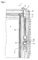
- FIG. 1 shows a portion of a residential roof window 1, which has a sash 2 with frame legs 3. Between the frame legs 3 and on the sash 2 a glazing 4 is provided. On the frame leg 3 is intended in FIG. 2 illustrated cover plate 5 are attached. For this purpose, a fastening device 6 is provided, which on the cover plate 5, a support member 7 and a rear handle member 8 and on the frame legs 3, a counter-support member 9 and a rear handle counter-element 10 provides.
- the rear grip element 8 is designed as a securing pin 11.
- a further support element 12 is provided on the cover plate 5
- a further counter-support element 13 is provided on the frame leg 3 in the region of the rear grip counter-element 10.
- the further counter-support element 13 is formed by the rear counter-counterpart element 10 with.
- the support element 7 with the counter-support element 9 and the further support member 12 with the other counter-support element 13 cooperate to hold the cover plate 5 axially immovable to the frame legs 3. At the same time a displacement of the cover plate 5 in the radial or lateral direction is prevented.
- the locking pin 11 is provided, which is slidably mounted with respect to the cover plate 5 and can be manually operated. In order to prevent the lifting, the locking pin 11 is actuated so that it is in its securing position.
- the attachment of the cover plate 5 on the frame member 3 is carried out as described below: First, the cover plate 5 is placed on the frame member 3, so that the support member 7 is disposed in the region of the counter-support member 9 and can be pushed onto this. Subsequently, the cover plate 5 is displaced in the axial direction until the counter-support element 9 or wing 14 of the counter-support element 9 engage in the support element 7. If the wings 14 are completely inserted into the support element 7, then the cover plate 5 bears against the frame limb 3. Subsequently, the locking pin 11 is actuated, that is displaced in its axial direction with respect to the cover plate 5, so that a rear grip connection of the locking pin 11 is made with the rear handle counter-element 10.
- the rear handle counter-element 10 may be formed for example U-shaped, so enclose the locking pin so at least partially.
- the cover plate 5 may be provided such that a bead 15 receives a projection 16 of the casement 2 in such a way to realize an additional guide of the cover plate 5 when pushed onto the frame leg 3.
- the engagement of the protrusion 16 in the bead 15 serves to achieve a good visual impression of the residential roof window.
- a further cover plate 17 is attached to the cover plate 5 by means of a mounting member 18.
- the mounting part 18 also has the locking pin 11 on or a bearing element 19, in which the locking pin 11 is guided displaceably.
- the locking pin 11 and the support member 7 are accordingly the cover plate 5 and the rear handle counter-element 10 and the counter-support member 9 and 13 associated with the frame leg 3.
- the support element 7 is designed as a drive-in pocket 20.
- An inner area of the entrance pocket 20 is bounded by a pocket wall 21. As in FIG. 2 it can be seen, this is at least partially formed by the cover plate 5.
- the support element 7 is arranged at a distance from the further support element 12 or the securing pin 11.
- the counter-support member 9 is spaced from the other counter-support member 13 and the rear handle counter-element 10.
- the support element 7 is fastened to the cover plate 5 by means of at least one rivet 22.
- mounting part 18 and the cover plate 5 and the further cover plate 17 is for example a snap-in connection. Again, however, may alternatively be provided a riveted connection.
- an additional cover plate can be attached by means of a further mounting part on the further cover plate 17, so that a U-shaped cover is present, which has on both sides via a locking pin 11, a support member 7 and another support member 12.
- the cover plate 5, the additional cover plate 17 and the additional cover plate are fastened together in the form of the cover member on the sash 2 and fixed by means of the fastening device 6.
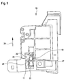
- FIG. 3 shows an enlarged view of the released mounting part 18. It can be seen that the locking pin 11 is arranged in the bearing element 19.
- the securing pin 11 has an actuating region 23, on which a fitter for displacing the securing pin 11 engages in its securing position.
- the FIG. 3 shows the locking pin 11 in its Abhebewolf. This means that in this position the cover plate 5 can be lifted off the frame leg 3. For shifting into the securing position, the securing pin 11 is moved in the direction of the arrow 24. In the FIG. 3 is indicated that the locking pin 11 via a Latch 25 has, which is part of a latching connection 26.
- the locking connection 26 represents a pull-out protection, thus preventing withdrawal of the locking pin 11 from the bearing element 19, starting from the position shown.
- the latching lug 25 or the latching connection 26 cooperates with a guide opening 27 of the bearing element 19.
- the guide opening 27 is penetrated by the locking pin 11, thus forms a storage for the locking pin 11 at least partially.
- the locking lug 25 cooperates with an edge 28 of the guide opening 27 to produce the latching connection between the locking pin 11 and the bearing element 19.
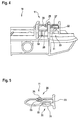
- FIG. 4 shows a portion of the mounting member 18 in a side view. It can be seen that the bearing element 19 has the guide opening 27 and a further guide opening 29. It is also clearly visible how the detent 25 cooperates with the edge 28 to prevent withdrawal of the locking pin 11 from the bearing element 19.
- the locking pin 11 has, in addition to the latching connection 26, a latching device 30. This has a latching projection 31, which is arranged on a spring bridge 32. The latching projection 31 prevents both unintentional introduction of the locking pin 11 in the bearing element 19, that is, a displacement of the locking pin 11 in its securing position. On the other hand, it prevents as soon as the locking pin 11 is in its securing position, a move out of this.
- the locking pin 11 can not be moved out of its secure position unintentionally.
- the spring bridge 31 is curved in the cross section of the locking pin 11 seen outwards, whereby a good spring action is achieved.
- the spring force of the spring bridge 32 urges the locking projection 31 of the locking pin 11 in its locking position, ie in a position in which both an accidental introduction and removal from the securing position is prevented.
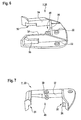
- FIG. 5 shows the release locking pin 11. Recognizable is the latching connection 26 and the latching device 30 and the actuating portion 23.
- the latching connection 26 has the locking lug 25, while the latching device 30 has the latching projection 31 on the spring bridge 32.
- the latching lug 25 of the latching connection 26 is located on a further spring bridge 33. However, this is small in comparison to the spring bridge 32, so that their spring action is low. This is due to the fact that the further spring bridge 33 is only required in order to allow the latching lug 25 to retract when the securing pin 11 is inserted into the bearing element 19. An application of the securing pin 11 from the bearing element 19 is usually not provided.
- FIG. 6 shows a view of the support element 7.
- This is designed as a entrance pocket 20.
- the support element 7 is fastened by means of rivets 22 to the cover plate 5.
- rear grip areas 35 are formed in lateral pocket walls 34, in which the wings 14 of the counter support element 9 can engage.
- the counter-support element is arranged in the mounting position of the cover plate 5 in the support element, wherein the wings 14 engage in the rear handle portions 35.
- the rear grip portions 35 can be opened or closed in the direction of the cover plate 5 either. In the former case, an area of the cover plate 5 forms a contact surface for the counter-support element 9 or its wings 14.
- a contact rail 36 is provided which limits the rear grip area 35 in the direction of the cover plate 5.
- a rear pocket wall 37 forms a contact surface for a front edge 38 of the counter-support element 9 (see FIG. 1 ). The leading edge 38 enters against the rear pocket wall 37 as soon as the cover plate 5 is in its mounting position. In this way, the axial support of the cover plate 5 is realized.
- a pin 39 is also provided, which fulfills the function of a blank holder 40.
- the pin 39 is bevelled in its front region, so that the counter-supporting element 9 runs on the pin 39 when it is pushed into the entry pocket 20.
- the counter-support element is thereby pushed away from the pin 39 of the cover plate 5.
- the counter-support member 9 is urged against an upper limit of the rear grip portions 35 and thus held firmly in this.
- the front edge 38 of the mating support member 9 abuts the rear pocket wall 37 and a portion of the mating support member 9 is based on the pin 39 from or rests on this, the wings 14 of the mating support member 9 against the upper limits of the rear grip areas 35 are urged.
- the wings 14 and the rear grip portions 35 and the locking pin 11 and the rear handle counter-element 10 thus form means 41st for radially non-displaceable support of the cover plate 5 on the frame legs. 5
- the locking pin 11 is equipped with a recognition feature which allows a fitter of the residential roof window 1 a clear recognition of the locking pin 11.
- the locking pin 11 is held in a signal color.
- signal color means that the color of colors of the surrounding components settles so far that a unambiguous identification is possible even in poor visibility.
- 23 transverse grooves are provided in the actuation region, which make it possible to feel the locking pin 11 and a secure operation.
Landscapes
- Engineering & Computer Science (AREA)
- General Engineering & Computer Science (AREA)
- Architecture (AREA)
- Civil Engineering (AREA)
- Structural Engineering (AREA)
- Mechanical Engineering (AREA)
- Operating, Guiding And Securing Of Roll- Type Closing Members (AREA)
- Emergency Lowering Means (AREA)
- Roof Covering Using Slabs Or Stiff Sheets (AREA)
Abstract
Description
Die Erfindung betrifft ein Wohndachfenster mit einem Flügelrahmen der Rahmenschenkel aufweist, wobei an mindestens einem der Rahmenschenkel ein Abdeckblech mittels einer Befestigungsvorrichtung befestigt ist. Die Erfindung betrifft weiterhin ein Verfahren zum Befestigen eines Abdeckblechs an einem Rahmenschenkel eines Wohndachfensters.The invention relates to a residential roof window having a sash of the frame legs, wherein a cover plate is secured by means of a fastening device on at least one of the frame legs. The invention further relates to a method for attaching a cover plate to a frame leg of a residential roof window.
Wohndachfenster der eingangs genannten Art sind aus dem Stand der Technik bekannt. Derartige Wohndachfenster weisen einen Flügelrahmen auf, an welchem eine Abdeckung in Form des Abdeckblechs vorgesehen ist. Das Abdeckblech dient zum einen dem Schutz des eigentlichen Flügelrahmens und zum anderen sorgt es für einen guten optischen Eindruck des Wohndachfensters. Das Abdeckblech besteht häufig aus einem oberflächenbehandelten, beispielsweise lackierten, Metall. Um das Abdeckblech an dem Rahmenschenkel des Flügelrahmens zu befestigen, ist die Befestigungsvorrichtung vorgesehen. Bekannt ist es, das Abdeckblech mittels Schrauben an dem Flügelrahmen zu befestigen. Die Befestigungsvorrichtung liegt demnach in Gestalt der Schraube beziehungsweise eines Bolzens vor. Eine derartige Befestigung ist jedoch unvorteilhaft, da sie zum einen zeitaufwendig ist, weil die Schraube mit dem Abdeckblech beziehungsweise dem Flügelrahmen verschraubt werden muss, und zum anderen, weil Bereiche der Befestigungsvorrichtung an dem Flügelrahmen sichtbar verbleiben können. Letzteres ist üblicherweise notwendig, um das Befestigen des Abdeckblechs und auch ein eventuell vorgesehenes Entfernen zu ermöglich. Beispielsweise verbleiben Schraubenköpfe in einem sichtbaren Bereich des Wohndachfensters.Roof windows of the type mentioned are known from the prior art. Such roof windows have a sash, on which a cover is provided in the form of the cover plate. On the one hand, the cover plate serves to protect the actual sash frame and, on the other hand, it ensures a good visual impression of the residential roof window. The cover plate often consists of a surface-treated, for example painted, metal. In order to secure the cover plate to the frame legs of the sash, the fastening device is provided. It is known to fasten the cover plate by means of screws to the casement. The fastening device is therefore in the form of the screw or a bolt. However, such attachment is disadvantageous because it is time consuming, because the screw must be bolted to the cover plate or the casement, and on the other hand, because areas of the fastening device can remain visible on the casement. The latter is usually necessary to allow the fastening of the cover plate and also a possibly provided removal. For example, screw heads remain in a visible area of the residential roof window.
Es ist somit Aufgabe der Erfindung, ein Wohndachfenster bereitzustellen, welches die eingangs genannten Nachteile nicht aufweist und insbesondere eine schnelle Montage des Abdeckblechs an dem Rahmenschenkel erlaubt. Weiterhin soll die Befestigung mittels der Befestigungsvorrichtung derart erfolgen, dass diese nicht sichtbar an dem Wohndachfenster verbleibt.It is therefore an object of the invention to provide a living roof window, which does not have the disadvantages mentioned above and in particular allows a quick mounting of the cover plate on the frame legs. Furthermore, the attachment by means of the fastening device should be such that it does not remain visible on the roof canopy.
Dies wird erfindungsgemäß erreicht, indem die Befestigungsvorrichtung mindestens ein Stützelement und mindestens ein damit zusammenwirkendes Gegenstützelement zur axial unverschieblichen Abstützung des Abdeckblechs am Rahmenschenkel und mindestens ein Hintergriffelement sowie ein damit zusammenwirkendes Hintergriffgegenelement zur Abhebeverhinderung des Abdeckblechs vom Rahmenschenkel aufweist, wobei das Hintergriffelement ein für sich verschiebbar gelagerter, manuell zu bedienender Sicherungsstift ist. Die Befestigungsvorrichtung sieht also jeweils mindestens ein Stützelement, Gegenstützelement, Hintergriffelement und Hintergriffgegenelement vor. Dabei wirkt das Stützelement mit dem mindestens einen Gegenstützelement und das Hintergriffelement mit dem mindestens einen Hintergriffgegenelement zusammen. Das Stützelement sorgt zusammen mit dem Gegenstützelement dafür, dass das Abdeckblech mit dem Rahmenschenkel derart gehalten ist, dass es axial zumindest in eine Richtung unverschieblich beziehungsweise abgestützt ist. Stützelement und Gegenstützelement bilden somit im Wesentlichen einen Endanschlag für das Abdeckblech in diese Richtung. Zu diesem Zweck sind Stützelement und Gegenstützelement beispielsweise ineinandersteckbar. Die Richtung ist vorzugsweise die Längsrichtung des Abdeckblechs beziehungsweise des Rahmenschenkels. Zusätzlich kann jedoch auch ein Abstützen in weitere Richtungen vorgesehen sein.This is inventively achieved by the attachment device comprises at least one support element and at least one cooperating counter-support member for axially non-displaceable support of the cover plate on the frame legs and at least one rear handle element and a cooperating rear handle counter-element for Abhebeverhinderung the cover plate from the frame legs, wherein the rear handle member slidably mounted in itself , manually operated locking pin is. The fastening device thus provides in each case at least one support element, counter support element, rear engagement element and rear engagement counter element. In this case, the support element interacts with the at least one counter-support element and the rear-engagement element with the at least one rear-engagement counter-element. The support element ensures, together with the counter-support element, that the cover plate is held with the frame limb in such a way that it is immovable or supported axially at least in one direction. Support element and counter-support element thus essentially form an end stop for the cover plate in this direction. For this purpose, the support element and the counter support element, for example, nestable. The direction is preferably the Longitudinal direction of the cover plate or the frame leg. In addition, however, can also be provided a support in other directions.
Dagegen sorgt das Hintergriffelement zusammen mit dem mindestens einem Hintergriffgegenelement dafür, dass das Abdeckblech nicht von dem Rahmenschenkel abgehoben werden kann. Sobald sich das Hintergriffelement in einer Sicherungsstellung befindet, ist das Abdeckblech sicher an dem Rahmenschenkel beziehungsweise dem Flügelrahmen gehalten. Das Hintergriffelement ist als Sicherungsstift ausgebildet, welcher verschiebbar gelagert ist und manuell betätigt werden kann. Solange sich der Sicherungsstift beziehungsweise das Hintergriffelement nicht in seiner Sicherungsstellung befindet, kann die Verbindung zwischen Stützelement und Gegenstützelement gelöst werden (beispielsweise durch Ausstecken), sodass die axial unverschiebliche Abstützung des Abdeckblechs am Rahmenschenkel nicht mehr vorliegt. Es kann vorgesehen sein, dass das Hintergriffgegenelement gleichzeitig auch das Gegenstützelement darstellt beziehungsweise dieses mit ausbildet, also ein Teil davon ist. Umgekehrt kann auch das Gegenstützelement das Hintergriffgegenelement ausbilden beziehungsweise ein Teil davon sein.On the other hand, the rear grip element together with the at least one rear grip counter element ensures that the cover plate can not be lifted off the frame leg. As soon as the rear grip element is in a securing position, the cover plate is securely held on the frame limb or the sash frame. The rear handle element is designed as a locking pin, which is displaceably mounted and can be operated manually. As long as the locking pin or the rear grip element is not in its securing position, the connection between the support element and the counter support element can be solved (for example, by unplugging), so that the axially non-displaceable support of the cover plate on the frame leg is no longer present. It can be provided that the rear counter-element at the same time also represents the counter-support element or forms this with, that is part of it. Conversely, the counter-support element can also form or be part of the rear-counterpart element.
Der Sicherungsstift kann zwischen der Sicherungsstellung und einer Abhebestellung verschoben werden. In der Abhebestellung liegt keine Hintergriffverbindung zwischen dem Hintergriffelement beziehungsweise dem Sicherungsstift und dem Hintergriffgegenelement vor, das Abdeckblech kann also von dem Rahmenschenkel abgehoben werden. Dagegen liegt in der Sicherungsstellung die Hintergriffverbindung, also eine formschlüssige Verbindung, vor, sodass das Abdeckblech an dem Rahmenschenkel gehalten ist. Steht das Stützelement auf diese Weise in Wirkverbindung mit dem Gegenstützelement und das Hintergriffelement mit dem Hintergriffgegenelement, so liegt eine Montageposition des Abdeckblechs an dem Rahmenschenkel vor. In dieser ist das Abdeckblech sicher an dem Rahmenschenkel beziehungsweise dem Flügelrahmen des Wohndachfensters gehalten, sodass ein unbeabsichtigtes Entfernen des Abdeckblechs von diesem nicht möglich ist. Der Sicherungsstift ist für sich verschiebbar, das heißt, er kann in Bezug zu dem Abdeckblech bewegt werden.The locking pin can be moved between the backup position and a take-off position. In the Abhebestellung is no rear grip connection between the rear handle element or the locking pin and the rear handle counter element, the cover plate can therefore be lifted from the frame legs. In contrast, in the securing position, the rear grip connection, ie a positive connection, before, so that the cover plate is held on the frame legs. Is the support element in this way in operative connection with the counter-support element and the rear-engagement element with the rear-engagement counter-element, there is a mounting position of the cover plate on the frame leg. In this, the cover plate is securely held on the frame legs or the sash of the residential roof window, so that unintentional removal of the cover plate is not possible from this. The locking pin is displaceable by itself, that is, it can be moved in relation to the cover plate.
Weitere vorteilhafte Ausgestaltungen ergeben sich aus den Unteransprüchen.Further advantageous embodiments will be apparent from the dependent claims.
Eine Weiterbildung der Erfindung sieht vor, dass die Befestigungsvorrichtung Mittel zur radial unverschieblichen Abstützung des Abdeckblechs am Rahmenschenkel aufweist. Radial unverschieblich bedeutet insbesondere, dass das Abdeckblech nicht in lateraler Richtung in Bezug auf den Rahmenschenkel bewegt werden kann, also in dieser Richtung festgesetzt ist. Das Abdeckblech ist also auch in Querrichtung des Rahmenschenkels an diesem gehalten. Die radiale Abstützung des Abdeckblechs kann durch Stützelement und Gegenstützelement und/oder Hintergriffelement und Hintergriffgegenelement realisiert sein. Es kann jedoch auch ein separates Mittel zu diesem Zweck vorgesehen sein. In der Montageposition des Abdeckblechs ist dieses somit sowohl in axialer als auch in radialer Richtung unverschieblich an dem Rahmenschenkel des Flügelrahmens gehalten. Da sich der Sicherungsstift in seiner Sicherungsstellung befindet, ist es zusätzlich gegen Abheben gesichert und somit an dem Rahmenschenkel des Flügelrahmens sicher befestigt.A development of the invention provides that the fastening device has means for radially non-displaceable support of the cover plate on the frame legs. Radially immovable means in particular that the cover plate can not be moved in the lateral direction with respect to the frame legs, that is fixed in this direction. The cover plate is therefore also held in the transverse direction of the frame leg at this. The radial support of the cover plate can be realized by the support element and the counter support element and / or the rear engagement element and the rear engagement counter element. However, a separate means for this purpose may also be provided. In the mounting position of the cover plate this is thus held immovably in the axial and in the radial direction of the frame legs of the sash. Since the locking pin is in its securing position, it is additionally secured against lifting and thus securely attached to the frame legs of the sash.
Nach einer Weiterbildung der Erfindung ist vorgesehen, dass dem Sicherungsstift eine ihn in seiner Sicherungsstellung lösbar haltende Rastvorrichtung zugeordnet ist. Wird der Sicherungsstift - insbesondere aus seiner Abhebestellung - in seine Sicherungsstellung verlagert, so verhindert die Rastvorrichtung, dass er unbeabsichtigt wieder aus dieser herausgelangen kann. Die Rastvorrichtung ist dabei zum lösbaren Halten vorgesehen. Das bedeutet, dass der in seine Sicherungsstellung verschobene Sicherungsstift lediglich durch eine manuelle Krafteinwirkung wieder aus der Sicherungsstellung herausgelangen kann. Ein Verschieben des Sicherungsstiftes unter Lösen der durch die Rastvorrichtung vorliegenden Verbindung ist beispielsweise vorgesehen, wenn das Abdeckblech von dem Rahmenschenkel entfernt werden soll (zum Beispiel zum Austausch/zur Reparatur des Abdeckblechs).According to a development of the invention it is provided that the locking pin is associated with a releasably holding it in its securing position locking device. If the locking pin - in particular shifted from its Abhebestellung - in its securing position, so prevents the locking device that he can accidentally get out of this again. The locking device is provided for releasable holding. This means that the locking pin, which has been moved into its securing position, can only come out of the securing position by a manual action of force. A displacement of the locking pin while releasing the present connection by the locking device is provided, for example, when the cover plate is to be removed from the frame legs (for example, for replacement / repair of the cover plate).
Eine vorteilhafte Weiterbildung der Erfindung sieht vor, dass der Sicherungsstift in einem Lagerelement verschieblich geführt ist. Die Lagerung des verschiebbar gelagerten Sicherungsstiftes wird mit dem Lagerelement realisiert. Dabei ist insbesondere eine axiale Lagerung des Sicherungsstifts vorgesehen. Der Sicherungsstift kann derart in dem Lagerelement verschoben werden, dass er manuell zumindest in seine Sicherungsstellung bringbar ist.An advantageous development of the invention provides that the locking pin is guided displaceably in a bearing element. The storage of the displaceably mounted locking pin is realized with the bearing element. In particular, an axial bearing of the locking pin is provided. The locking pin can be moved in the bearing element such that it can be brought manually at least into its securing position.
Eine weitere Ausgestaltung der Erfindung sieht vor, dass der Sicherungsstift an dem Lagerelement mittels einer Rastverbindung unverlierbar gehalten ist. Die Rastverbindung verhindert, dass der Sicherungsstift aus dem Lagerelement hinausgelangen kann. Die Rastverbindung kann dabei lösbar sein, das bedeutet, dass der Sicherungsstift manuell aus dem Lagerelement entnommen werden kann, jedoch ein unbeabsichtigtes Herausgelangen - also Verlieren - verhindert ist. Die Rastverbindung wirkt insbesondere derart, dass der Sicherungsstift aus seiner Abhebestellung nicht aus dem Lagerelement herausgelangen kann.A further embodiment of the invention provides that the locking pin is held captive on the bearing element by means of a latching connection. The latching connection prevents the locking pin from getting out of the bearing element. The locking connection can be detachable, which means that the locking pin can be manually removed from the bearing element, but unintentional getting out - so losing - prevented is. The latching connection acts in particular such that the locking pin can not get out of the bearing element from its Abhebestellung.
Bevorzugt ist dabei die Rastverbindung ein Herausziehschutz. Sie ist somit zur Verhinderung eines Herausziehens und/oder Herausfallens des Sicherungsstiftes aus dem Lagerelement ausgebildet. Ein unbeabsichtigtes Herausziehen/Herausfallen ist damit verhindert. Lediglich bei einer (manuellen) Betätigung der Rastverbindung ist ein Herausnehmen des Sicherungsstiftes aus dem Lagerelement möglich. Vorteilhafterweise ist die Rastverbindung derart ausgebildet, dass ein Verrasten des Sicherungsstifts an dem Lagerelement vorgesehen ist, sobald der Sicherungsstift in das Lagerelement eingeschoben wird.Preferably, the locking connection is a pull-out protection. It is thus designed to prevent withdrawal and / or falling out of the locking pin from the bearing element. Unintentional withdrawal / falling out is prevented. Only with a (manual) operation of the locking connection is a removal of the locking pin from the bearing element possible. Advantageously, the latching connection is designed such that a locking of the locking pin is provided on the bearing element as soon as the locking pin is inserted into the bearing element.
In einer bevorzugten Weiterbildung ist vorgesehen, dass die Rastverbindung eine Rastnase am Sicherungsstift aufweist, die mit einer vom Sicherungsstift durchsetzten Führungsöffnung des Lagerelements zusammenwirkt. Die Rastnase ist das verrastende Element der Rastverbindung. Bei einem Herstellen der Rastverbindung rastet also die Rastnase derart ein, dass der Sicherungsstift an dem Lagerelement unverlierbar gehalten ist. Dabei wirkt die Rastnase mit der Führungsöffnung zusammen, die in dem Lagerelement vorgesehen und von dem Sicherungsstift durchsetzt ist. Das verschiebliche Führen des Sicherungsstifts in dem Lagerelement wird von der Führungsöffnung realisiert. Der Führungsstift ist dabei in dieser angeordnet. Die Führungsöffnung erlaubt also ein Verschieben des Sicherungsstiftes zumindest in seine Sicherungsstellung. Der Sicherungsstift ist so in der Führungsordnung angeordnet, dass die Rastnase ein Herausbewegen aus der Führungsöffnung beziehungsweise dem Lagerelement nicht zulässt. Die Rastnase greift dabei an einem Rand der Führungsöffnung an.In a preferred embodiment, it is provided that the latching connection has a detent on the locking pin, which cooperates with a traversed by the locking pin guide opening of the bearing element. The locking lug is the latching element of the latching connection. When the latching connection is produced, the latching lug thus engages in such a way that the securing pin is held captive on the bearing element. In this case, the latching nose cooperates with the guide opening, which is provided in the bearing element and penetrated by the locking pin. The displaceable guiding of the securing pin in the bearing element is realized by the guide opening. The guide pin is arranged in this. The guide opening thus allows a displacement of the locking pin at least in its securing position. The locking pin is arranged in the guide order, that the latch a move out of the guide opening or does not allow the bearing element. The detent engages on an edge of the guide opening.
Eine Weiterbildung der Erfindung sieht vor, dass die Rastvorrichtung einen Rastvorsprung am Sicherungsstift aufweist, der mit der Führungsöffnung oder einer vom Sicherungsstift durchsetzten weiteren Führungsöffnung des Lagerelements zusammenwirkt. Zusätzlich oder alternativ zu der Rastnase weist der Sicherungsstift somit den Rastvorsprung auf. Dieser kann mit derselben Führungsöffnung wie die Rastnase oder mit einer weiteren Führungsöffnung des Lagerelements zusammenwirken, um den Sicherungsstift in seiner Sicherungsstellung lösbar zu halten. Der Rastvorsprung greift dabei beispielsweise an dem Rand der Führungsöffnung oder der weiteren Führungsöffnung an. Zusammen mit dem Rastvorsprung weist der Sicherungsstift also größere Abmessungen auf als die Führungsöffnung. Dies ist in mindestens einer Erstreckungsrichtung des Sicherungsstifts vorgesehen. Der Rastvorsprung übergreift dabei die Führungsöffnung oder die weitere Führungsöffnung, sodass ein unbeabsichtigtes Herausbewegen des Sicherungsstiftes aus dem Lagerelement, das heißt ein Herausbewegen aus der Sicherungsstellung, nicht möglich ist. Lediglich durch Aufbringen einer gewissen Kraft, insbesondere durch manuellen Einfluss, kann der Sicherungsstift unter Lösen der Rastverbindung zwischen Rastvorsprung und Führungsöffnung aus seiner Sicherungsstellung herausbewegt werden.A further development of the invention provides that the latching device has a latching projection on the locking pin, which cooperates with the guide opening or a further guided by the locking pin further guide opening of the bearing element. In addition or as an alternative to the latching lug, the securing pin thus has the latching projection. This can cooperate with the same guide opening as the locking lug or with a further guide opening of the bearing element to releasably hold the securing pin in its securing position. The latching projection acts, for example, on the edge of the guide opening or the further guide opening. Together with the latching projection, the locking pin thus has larger dimensions than the guide opening. This is provided in at least one extension direction of the securing pin. The latching projection engages over the guide opening or the further guide opening, so that an unintentional moving out of the locking pin from the bearing element, that is, a moving out of the securing position, is not possible. Only by applying a certain force, in particular by manual influence, the locking pin can be moved under release of the locking connection between locking projection and guide opening from its securing position.
Nach einer vorteilhaften Weiterbildung der Erfindung ist der Rastvorsprung an einer Federbrücke vorgesehen. Die Federbrücke ist eine brückenartige Ausbildung an dem Sicherungsstift. Sie weist eine Federwirkung auf, die ein Zurückweichen des Rastvorsprungs erlaubt. Gleichzeitig drängt sie den Rastvorsprung in seine Raststellung, also in eine Stellung, in welcher der Sicherungsstift in seiner Sicherungsstellung gehalten ist. Die Federbrücke ist an ihren Enden mit dem Sicherungsstift verbunden. Der zwischen den Enden ausgebildete Bereich ist von restlichen Bereichen des Sicherungsstiftes beabstandet. Der Querschnitt der Federbrücke ist im Wesentlichen rechteckig, wobei er derart gewählt ist, um eine ausreichende Federwirkung auf den Rastvorsprung auszuüben. Die Federbrücke kann zum Ausüben der Federkraft beziehungsweise zum Erreichen einer gewissen Biegesteifigkeit nach außen gewölbt sein, wobei die Wölbung entgegen einer Kraft ausgebildet ist, die auf ein Herausbewegen der Rastvorrichtung aus ihrer Rastposition gerichtet ist. Zwischen der Federbrücke und dem restlichen Bereich des Sicherungsstifts ist demnach ein Freiraum vorgesehen.According to an advantageous embodiment of the invention, the latching projection is provided on a spring bridge. The spring bridge is a bridge-like design on the locking pin. It has a spring action, which allows a retraction of the locking projection. At the same time it urges the locking projection in its rest position, so in a position in which the locking pin is held in its securing position. The spring bridge is connected at its ends with the locking pin. The area formed between the ends is spaced from remaining areas of the locking pin. The cross section of the spring bridge is substantially rectangular, wherein it is chosen such that it exerts sufficient spring action on the latching projection. The spring bridge can be arched to exert the spring force or to achieve a certain bending stiffness to the outside, wherein the curvature is formed against a force that is directed to a moving out of the locking device from its rest position. Accordingly, a free space is provided between the spring bridge and the remaining area of the securing pin.
Eine bevorzugte Weiterbildung sieht vor, dass Rastnase und Rastvorsprung einstückig mit dem Sicherungsstift ausgebildet sind. Rastnase und Rastvorsprung sind derart an dem Sicherungsstift vorgesehen, dass lediglich ein Bauteil vorliegt. Insbesondere sind Rastnase und Rastvorsprung dabei materialeinheitlich zu dem Sicherungsstift. Rastnase und Rastvorsprung können bei der Herstellung des Sicherungsstiftes mit ausgebildet sein. Die Herstellung kann beispielsweise mittels eines Spritzgießverfahrens erfolgen. Sind Rastnase und/oder Rastvorsprung auf der Federbrücke angeordnet, so ist auch die Federbrücke einstückig mit dem Sicherungsstift ausgebildet.A preferred embodiment provides that locking lug and latching projection are integrally formed with the locking pin. Locking lug and locking projection are provided on the locking pin, that only one component is present. In particular, latching lug and locking projection are the same material to the locking pin. Latch and latching projection may be formed in the manufacture of the locking pin with. The preparation can be done for example by means of an injection molding process. Are latching lug and / or latching projection arranged on the spring bridge, then the spring bridge is formed integrally with the locking pin.
Bevorzugt ist vorgesehen, dass der Sicherungsstift dem Abdeckblech und das Hintergriffgegenelement dem Rahmenschenkel zugeordnet ist. Ebenso kann vorgesehen sein, dass das Stützelement dem Abdeckblech und das Gegenstützelement dem Rahmenschenkel zugeordnet ist.It is preferably provided that the locking pin is assigned to the cover plate and the rear handle counter-element to the frame legs. Likewise, it can be provided that the support element the cover plate and the counter-support member is associated with the frame legs.
In einer bevorzugten Weiterbildung der Erfindung ist das Stützelement dem Abdeckblech und das Gegenstützelement dem Rahmenschenkel zugeordnet. Alternativ können selbstverständlich Sicherungsstift und/oder Stützelement auch dem Rahmenschenkel und Hintergriffgegenelement und/oder Gegenstützelement dem Abdeckblech zugeordnet sein.In a preferred development of the invention, the support element is assigned to the cover plate and the counter-support element is assigned to the frame limb. Alternatively, of course, locking pin and / or support element may also be assigned to the frame limb and the rearward counter-element and / or counter-support element to the cover plate.
Eine Weiterbildung der Erfindung sieht vor, dass das Stützelement als Einfahrtasche ausgebildet ist. Das Stützelement ist demnach taschenförmig mit einem Einschub zum Einschieben des Gegenstützelements vorgesehen. Taschenförmig bedeutet, dass eine Ausnehmung zur Aufnahme des Gegenstützelements das Stützelement nicht vollständig durchgreift, sondern eine Sacköffnung vorliegt. Die Einfahrtasche weist eine Form dergestalt auf, dass das Gegenstützelement nach einem Einbringen in die Einfahrtasche zumindest axial unverschieblich abgestützt ist. Zusätzlich kann auch eine radiale Lagerung des Gegenstützelements vorgesehen sein. Das Stützelement weist dabei eine Sackausnehmung auf, die vorteilhafterweise im Wesentlichen rechteckigen Querschnitt hat.A development of the invention provides that the support element is designed as a driveway. The support element is thus provided pocket-shaped with a slot for insertion of the counter-supporting element. Pocket-shaped means that a recess for receiving the counter-support element does not fully penetrate the support element, but a blind opening is present. The Einfahrtasche has a shape such that the counter-support element is supported after insertion into the entrance pocket at least axially immovable. In addition, a radial bearing of the counter-support element may also be provided. The support element in this case has a blind recess, which advantageously has a substantially rectangular cross-section.
Eine weitere Ausgestaltung der Erfindung sieht vor, dass eine Taschenwand der Einfahrtasche zumindest bereichsweise von dem Abdeckblech gebildet ist. Ist das Stützelement an dem Abdeckelement angebracht - beispielsweise mittels einer Nietverbindung -, so kann es vorgesehen sein, dass das Abdeckblech die Taschenwand der Einfahrtasche zumindest bereichsweise ausbildet. Das Abdeckblech bildet also eine Anlagefläche für das Gegenstützelement. In diesem Fall bildet das Stützelement zusammen mit dem Abdeckblech die Einfahrtasche. Es ist also nicht notwendig, dass das Stützelement zum vollständigen Umgreifen des Gegenstützelements ausgestaltet ist.A further embodiment of the invention provides that a pocket wall of the entrance pocket is at least partially formed by the cover plate. If the support element is attached to the cover element-for example by means of a riveted connection-it can be provided that the cover plate forms the pocket wall of the entrance pocket at least in certain areas. The cover plate thus forms a contact surface for the counter-support element. In In this case, the support element together with the cover plate forms the entrance pocket. It is therefore not necessary that the support element is designed to fully encompass the counter-support element.
Zweckmäßigerweise ist vorgesehen, dass das Stützelement das Gegenstützelement radial unverschieblich hält. Zu diesem Zweck kann es das Gegenstützelement zumindest bereichsweise umfassen beziehungsweise umgreifen. Das Gegenstützelement wirkt also mit dem Stützelement zusammen, um sowohl das Abdeckblech axial unverschieblich abzustützen, als auch radial unverschieblich zu halten.Appropriately, it is provided that the support element holds the counter-support element radially immovable. For this purpose, it may at least partially encompass or encompass the counter-support element. The counter-support member thus cooperates with the support member to support both the cover axially immovable, as well as to hold radially immovable.
In einer bevorzugten Weiterbildung weist das Gegenstützelement mindestens einen sich im Wesentlichen parallel zu dem Abstützblech erstreckenden Flügel auf. Die Flügel werden von Vorsprüngen gebildet, welche sich beispielsweise ausgehend von dem Regelgegenstützelement radial beziehungsweise in lateraler Richtung nach außen erstrecken. Die Flügel können dazu vorgesehen sein, das Gegenstützelement in dem Stützelement zu halten. Es ist also nicht notwendig, dass das Gegenstützelement vollständig in das Stützelement eingreift, dies kann lediglich im Bereich der Flügel vorgesehen sein. Die Flügel erstrecken sich dabei im Wesentlichen parallel zu dem Abstützblech, wobei ein Winkelversatz in Grenzen zulässig ist.In a preferred development, the counter-support element has at least one wing extending substantially parallel to the support plate. The wings are formed by projections, which extend, for example, starting from the rule-counter-support element radially or in the lateral direction to the outside. The wings may be provided to hold the counter-support member in the support member. It is therefore not necessary that the counter-support element engages completely in the support element, this can be provided only in the region of the wings. The wings extend substantially parallel to the support plate, wherein an angular offset is permitted within limits.
Nach einer vorteilhaften Weiterbildung der Erfindung weist die Einfahrtasche mindestens einen Hintergriffbereich auf, in welchen der Flügel des Gegenstützelements eingreift. Demnach ist vorgesehen, dass der Flügel mit dem Hintergriffbereich zusammenwirkt, um das Abdeckblech am Rahmenschenkel axial unverschieblich abzustützen. Sind mehrere Flügel vorgesehen, so kann gleichzeitig auch ein Verkippen des Abdeckblechs - insbesondere um eine Längsachse - in Bezug zu dem Rahmenschenkel verhindert werden.According to an advantageous development of the invention, the entrance pocket has at least one rear grip area, in which the wing of the counter-support element engages. Accordingly, it is provided that the wing cooperates with the rear grip area to the Cover plate to support the frame legs axially immovable. If several wings are provided, tilting of the cover plate-in particular about a longitudinal axis-can also be prevented at the same time with respect to the frame limb.
Eine vorteilhafte Ausgestaltung der Erfindung sieht vor, dass das Stützelement und das Hintergriffelement beabstandet zueinander angeordnet sind. Damit liegen auch das Gegenstützelement und das Hintergriffgegenelement zueinander beabstandet vor. Durch die beabstandete Anordnung kann eine optimale Haltewirkung des Abdeckblechs an dem Rahmenschenkel gewährleistet werden. Insbesondere wird ein Verdrehen beziehungsweise Verkippen des Abdeckblechs gegenüber dem Rahmenschenkel verhindert. Auf diese Weise kann eine stabile und dauerhafte Verbindung zwischen Abdeckblech und Rahmenschenkel gewährleistet werden.An advantageous embodiment of the invention provides that the support element and the rear handle element are arranged spaced from each other. Thus, the counter-support element and the rearward counter-element are also at a distance from each other. Due to the spaced arrangement, an optimal holding action of the cover plate can be ensured on the frame legs. In particular, a twisting or tilting of the cover plate relative to the frame legs is prevented. In this way, a stable and durable connection between cover plate and frame legs can be ensured.
Die Erfindung betrifft ferner ein Verfahren zum Befestigen eines Abdeckblechs an einem Rahmenschenkel eines Flügelrahmens eines Wohndachfensters, insbesondere gemäß den vorstehenden Ausführungen, wobei das Abdeckblech an dem Rahmenschenkel mittels einer Befestigungsvorrichtung befestigt wird. Dabei ist vorgesehen, dass ein Stützelement der Befestigungsvorrichtung mit einem Gegenstützelement der Befestigungsvorrichtung in Eingriff gebracht wird, sodass das Abdeckblech axial unverschieblich an dem Rahmenschenkel abgestützt ist und anschließend ein als Sicherungsstift ausgebildetes Hintergriffelement betätigt wird, sodass das Hintergriffelement zur Abhebeverhinderung des Abdeckblechs vom Rahmenschenkel mit einem Hintergriffgegenelement zusammenwirkt. Zum Befestigen des Abdeckblechs an dem Rahmenschenkel sind demnach zwei Arbeitsschritte notwendig. Zum einen muss das Stützelement mit dem Gegenstützelement in Eingriff gebracht werden. Dies erfolgt beispielsweise durch Einschieben des Gegenstützelements in das Stützelement in axialer Richtung des Rahmenschenkels. Durch das Zusammenwirken des Gegenstützelements mit dem Stützelement ist das Abdeckblech axial unverschieblich an dem Rahmenschenkel abgestützt. Zusätzlich kann auch eine Abstützung in radialer Richtung beziehungsweise lateraler Richtung vorgesehen sein. Nach dem In-Eingriff-Bringen des Gegenstützelements mit dem Stützelement wird der Sicherungsstift betätigt, sodass dieser in ein Hintergriffgegenelement eingreift. Dies verhindert ein Abheben des Abdeckblechs von dem Rahmenschenkel. Durch das Verhindern des Abhebens kann ebenso das Stützelement nicht mehr aus dem Gegenstützelement ausgebracht werden, sodass eine dauerhafte Verbindung des Abdeckblechs mit dem Rahmenschenkel beziehungsweise dem Flügelrahmen hergestellt ist.The invention further relates to a method for attaching a cover plate to a frame leg of a sash of a residential roof window, in particular according to the preceding embodiments, wherein the cover plate is attached to the frame legs by means of a fastening device. It is envisaged that a support element of the fastening device is brought into engagement with a counter-supporting element of the fastening device, so that the cover plate is supported axially non-displaceably on the frame legs and then a trained as a locking pin rear handle element is actuated, so that the rear handle for Abhebeverhinderung the cover plate from the frame legs with a Rear counter-element cooperates. For fixing the cover plate to the frame legs therefore two steps are necessary. For one thing, that has to be Support element are brought into engagement with the counter-support element. This is done, for example, by inserting the counter-support element into the support element in the axial direction of the frame leg. Due to the interaction of the counter-support element with the support element, the cover plate is supported axially immovably on the frame legs. In addition, a support in the radial direction or lateral direction may be provided. After engaging the counter-support member with the support member, the locking pin is actuated to engage a counter-engagement member. This prevents lifting of the cover plate from the frame legs. By preventing the lifting off, the support element can likewise no longer be removed from the counter-support element, so that a permanent connection of the cover plate to the frame leg or the casement is produced.
Die Erfindung wird im Folgenden anhand der in der Zeichnung dargestellten Ausführungsbeispiele näher erläutert, ohne dass eine Beschränkung der Erfindung erfolgt. Es zeigen:
- Figur 1
- einen Ausschnitt eines Wohndachfensters mit einem Rahmenschenkel aufweisenden Flügelrahmen,
Figur 2- zwei aneinander befestigte Abdeckbleche zur Befesti- gung an dem Rahmenschenkel, wobei die beiden Ab- deckbleche mittels eines Montageteils aneinander be- festigt sind und zur Befestigung an dem Rahmen- schenkel ein Stützelement vorgesehen ist,
- Figur 3
- das Montageteil, wobei an diesem ein als Sicherungs- stift ausgebildetes Hintergriffgegenelement vorgesehen ist,
Figur 4- das Montageteil aus
Figur 3 in einer Seitenansicht, Figur 5- der Sicherungsstift,
Figur 6das aus Figur 2 bekannte Stützelement, undFigur 7- das Stützelement in einer weiteren Ansicht.
- FIG. 1
- a section of a rooftop window with a frame leg having wing frame,
- FIG. 2
- two cover plates fastened to one another for fastening to the frame limb, wherein the two cover plates are fastened to one another by means of a mounting part and a support element is provided for attachment to the frame limb,
- FIG. 3
- the mounting part, wherein this is provided as a safety pin trained counter-grip counter element,
- FIG. 4
- the mounting part off
FIG. 3 in a side view, - FIG. 5
- the locking pin,
- FIG. 6
- the end
FIG. 2 known support element, and - FIG. 7
- the support element in another view.
Die
Bei einer Befestigung des Abdeckblechs 5 an dem Rahmenschenkel 3 ist vorgesehen, dass das Stützelement 7 mit dem Gegenstützelement 9 und das weitere Stützelement 12 mit dem weiteren Gegenstützelement 13 zusammenwirken, um das Abdeckblech 5 axial unverschieblich an dem Rahmenschenkel 3 zu halten. Gleichzeitig wird eine Verschiebung des Abdeckblechs 5 in radialer beziehungsweise lateraler Richtung verhindert. Steht also das Stützelement 7 in Eingriff mit dem Gegenstützelement 9 und das weitere Stützelement 12 mit dem weiteren Gegenstützelement 13, so ist lediglich ein Abheben des Abdeckblechs 5 von dem Rahmenschenkel 3 möglich, da sowohl ein Verschieben in axialer als auch in lateraler Richtung nicht möglich ist. Um das Abheben zu verhindern, ist der Sicherungsstift 11 vorgesehen, welcher in Bezug auf das Abdeckblech 5 verschiebbar gelagert ist und manuell betätigt werden kann. Um das Abheben zu verhindern, wird der Sicherungsstift 11 betätigt, sodass dieser in seiner Sicherungsstellung vorliegt.When mounting the
Das Anbringen des Abdeckblechs 5 an dem Rahmenschenkel 3 erfolgt wie nachfolgend beschrieben: Zunächst wird das Abdeckblech 5 auf den Rahmenschenkel 3 aufgelegt, sodass das Stützelement 7 im Bereich des Gegenstützelements 9 angeordnet ist und auf dieses aufgeschoben werden kann. Anschließend wird das Abdeckblech 5 in axialer Richtung verschoben, bis das Gegenstützelement 9 beziehungsweise Flügel 14 des Gegenstützelements 9 in das Stützelement 7 eingreifen. Sind die Flügel 14 vollständig in das Stützelement 7 eingebracht, so liegt das Abdeckblech 5 an dem Rahmenschenkel 3 an. Nachfolgend wird der Sicherungsstift 11 betätigt, das heißt in seiner axialen Richtung in Bezug zu dem Abdeckblech 5 verschoben, sodass eine Hintergriffverbindung des Sicherungsstiftes 11 mit dem Hintergriffgegenelement 10 hergestellt ist. Das Hintergriffgegenelement 10 kann dabei beispielsweise U-förmig ausgebildet sein, den Sicherungsstift also zumindest bereichsweise umschließen.The attachment of the
Das Abdeckblech 5 kann dergestalt vorgesehen sein, dass eine Sicke 15 einen Vorsprung 16 des Flügelrahmens 2 derart aufnimmt, um eine zusätzliche Führung des Abdeckblechs 5 beim Aufschieben auf den Rahmenschenkel 3 zu realisieren. Zusätzlich dient das Eingreifen des Vorsprungs 16 in die Sicke 15 dem Erzielen eines guten optischen Eindrucks des Wohndachfensters 1.The
Wie in
Das Stützelement 7 ist als Einfahrtasche 20 ausgebildet. Das bedeutet, dass das Gegenstützelement 9 in die Einfahrtasche 20 eingebracht werden kann, diese aber zumindest einseitig eine Abstützung aufweist, an welcher sich das Gegenstützelement 9 abstützen kann, sodass die axial unverschiebliche Abstützung des Abdeckblechs 5 an dem Rahmenschenkel 3 gewährleistet ist. Ein Innenbereich der Einfahrtasche 20 wird von einer Taschenwand 21 begrenzt. Wie in
Das Stützelement 7 ist von dem weiteren Stützelement 12 beziehungsweise dem Sicherungsstift 11 beabstandet angeordnet. Damit ist auch das Gegenstützelement 9 beabstandet von dem weiteren Gegenstützelement 13 sowie dem Hintergriffgegenelement 10. Auf diese Weise wird ein Verkippen beziehungsweise Verdrehen des Abdeckblechs 5 gegenüber dem Rahmenschenkel 3 wirkungsvoll verhindert, da durch die Beabstandung eine Hebelwirkung vorliegt. Dies gewährleistet eine stabile Verbindung zwischen Abdeckblech 5 und Rahmenschenkel 3 beziehungsweise Flügelrahmen 2.The
Das Stützelement 7 ist mittels mindestens einer Niete 22 an dem Abdeckblech 5 befestigt. Zwischen Montageteil 18 und dem Abdeckblech 5 sowie dem weiteren Abdeckblech 17 liegt beispielsweise eine Rastverbindung vor. Auch hier kann jedoch alternativ eine Nietverbindung vorgesehen sein. In den
Die
Die
Die
Die
An der hinteren Taschenwand 37 ist außerdem ein Zapfen 39 vorgesehen, der die Funktion eines Niederhalters 40 erfüllt. Der Zapfen 39 ist in seinem vorderen Bereich angeschrägt, sodass das Gegenstützelement 9 bei einem Einschieben in die Einfahrtasche 20 auf den Zapfen 39 aufläuft. Das Gegenstützelement wird dabei von dem Zapfen 39 von dem Abdeckblech 5 weggedrängt. Somit wird das Gegenstützelement 9 gegen eine obere Begrenzung der Hintergriffbereiche 35 gedrängt und somit fest in diesen gehalten. In der Montageposition des Abdeckblechs 5 stößt die Vorderkante 38 des Gegenstützelements 9 an die hintere Taschenwand 37 und ein Bereich des Gegenstützelements 9 stützt sich auf dem Zapfen 39 ab beziehungsweise liegt auf diesem auf, wobei die Flügel 14 des Gegenstützelements 9 gegen die oberen Begrenzungen der Hintergriffbereiche 35 gedrängt werden. Gleichzeitig liegen Seitenkanten der Flügel 14 an der Innenseite der Hintergriffbereiche 35 an. Auf diese Weise ist sowohl ein laterales und axiales Verschieben als auch - im Bereich des Stützelements 7 - ein Abheben des Abdeckblechs 5 von dem Rahmenschenkel 3 nicht möglich.On the
Die Flügel 14 und die Hintergriffbereiche 35 sowie der Sicherungsstift 11 und das Hintergriffgegenelement 10 bilden folglich Mittel 41 zur radial unverschieblichen Abstützung des Abdeckblechs 5 an dem Rahmenschenkel 5.The
Der Sicherungsstift 11 ist mit einem Erkennungsmerkmal ausgestattet, welches einem Monteur des Wohndachfensters 1 eine zweifelsfreie Erkennung des Sicherungsstiftes 11 erlaubt. In dem hier dargestellten Beispiel ist der Sicherungsstift 11 in einer Signalfarbe gehalten. Dabei bedeutet Signalfarbe, dass sich die Farbe von Farben der umgebenden Bauteile soweit absetzt, dass eine zweifelsfreie Identifikation auch bei schlechten Sichtverhältnissen möglich ist. Zusätzlich sind in dem Betätigungsbereich 23 Querrillen vorgesehen, welche ein Ertasten des Sicherungsstiftes 11 sowie eine sichere Betätigung möglich machen.The locking
Claims (19)
Applications Claiming Priority (1)
| Application Number | Priority Date | Filing Date | Title |
|---|---|---|---|
| DE102009033939A DE102009033939B4 (en) | 2009-07-14 | 2009-07-14 | Roof window and method for fixing a cover plate |
Publications (3)
| Publication Number | Publication Date |
|---|---|
| EP2287416A2 true EP2287416A2 (en) | 2011-02-23 |
| EP2287416A3 EP2287416A3 (en) | 2015-06-17 |
| EP2287416B1 EP2287416B1 (en) | 2016-10-12 |
Family
ID=42973844
Family Applications (1)
| Application Number | Title | Priority Date | Filing Date |
|---|---|---|---|
| EP10006079.7A Active EP2287416B1 (en) | 2009-07-14 | 2010-06-11 | Skylight with means for fixing a cover plate and method for fixing the cover plate |
Country Status (3)
| Country | Link |
|---|---|
| EP (1) | EP2287416B1 (en) |
| DE (1) | DE102009033939B4 (en) |
| PL (1) | PL2287416T3 (en) |
Cited By (2)
| Publication number | Priority date | Publication date | Assignee | Title |
|---|---|---|---|---|
| EP2947226A1 (en) * | 2014-05-22 | 2015-11-25 | Roto Frank Ag | Residential skylight with flashing for covering outer areas of a wing frame and a sash frame |
| EP3045609A1 (en) * | 2015-01-19 | 2016-07-20 | FAKRO PP Sp. z o.o. | A roof window or a roof hatch with a sash openable outwards with a fixing assembly for the upper casing element |
Families Citing this family (1)
| Publication number | Priority date | Publication date | Assignee | Title |
|---|---|---|---|---|
| CN102140880B (en) * | 2011-03-18 | 2012-09-26 | 湖南鑫美格新型装饰材料有限公司 | Baseboard for preventing dampness and corrosion of door pocket and door pocket having same |
Family Cites Families (5)
| Publication number | Priority date | Publication date | Assignee | Title |
|---|---|---|---|---|
| DE9016725U1 (en) * | 1990-12-11 | 1991-03-28 | Roto Frank AG, 7022 Leinfelden-Echterdingen | Cover for a sash frame of a roof window |
| DE10217532A1 (en) * | 2002-04-17 | 2003-11-13 | Roto Frank Ag | Roof window with clipped cover |
| CN2714760Y (en) * | 2003-11-21 | 2005-08-03 | Vkr控股公司 | Window top cover plate |
| EP1533440A3 (en) * | 2003-11-21 | 2008-04-02 | VKR Holding A/S | Sealing sash frame and roof window equipped therewith |
| PL2242889T3 (en) * | 2007-12-19 | 2016-03-31 | Vkr Holding As | Weather shield |
-
2009
- 2009-07-14 DE DE102009033939A patent/DE102009033939B4/en not_active Expired - Fee Related
-
2010
- 2010-06-11 EP EP10006079.7A patent/EP2287416B1/en active Active
- 2010-06-11 PL PL10006079T patent/PL2287416T3/en unknown
Non-Patent Citations (1)
| Title |
|---|
| None |
Cited By (2)
| Publication number | Priority date | Publication date | Assignee | Title |
|---|---|---|---|---|
| EP2947226A1 (en) * | 2014-05-22 | 2015-11-25 | Roto Frank Ag | Residential skylight with flashing for covering outer areas of a wing frame and a sash frame |
| EP3045609A1 (en) * | 2015-01-19 | 2016-07-20 | FAKRO PP Sp. z o.o. | A roof window or a roof hatch with a sash openable outwards with a fixing assembly for the upper casing element |
Also Published As
| Publication number | Publication date |
|---|---|
| EP2287416B1 (en) | 2016-10-12 |
| DE102009033939A1 (en) | 2011-02-10 |
| PL2287416T3 (en) | 2017-03-31 |
| DE102009033939B4 (en) | 2011-07-21 |
| EP2287416A3 (en) | 2015-06-17 |
Similar Documents
| Publication | Publication Date | Title |
|---|---|---|
| EP3408484B1 (en) | Window lifter assembly with multipart pane guide element for a flush pane design, and assembly method | |
| EP2059148B1 (en) | Drawer | |
| DE69705662T2 (en) | Rolling device for sliding doors, windows or the like | |
| EP1857688A2 (en) | Clip-on or snap-on fastener for fastening a thin wall to a wall support | |
| DE102017113063A1 (en) | DIN rail mounting | |
| EP2287416B1 (en) | Skylight with means for fixing a cover plate and method for fixing the cover plate | |
| DE102006012063B4 (en) | Outside door handle for a motor vehicle | |
| DE102019205830A1 (en) | Fastening element and fastening arrangement for a motor vehicle body | |
| DE102009033938B4 (en) | Roof window and method for fixing a cover plate | |
| DE102009033941B4 (en) | Roof window with a sash | |
| DE102009018781B4 (en) | joint assembly | |
| EP2947221B1 (en) | Roof window and method for mounting a roof window | |
| DE102013100922A1 (en) | Running part for guiding a furniture part in a guide direction via a guide rail and furniture fitting | |
| EP3235984B1 (en) | Fitting for a window, method for producing the fitting and corresponding window | |
| EP2317047A2 (en) | Fitting device | |
| DE102021125772B4 (en) | Spacer, guide rail for a venetian blind or venetian blind and venetian blind and blind and method therefor | |
| DE69205091T2 (en) | Lifting prevention device for sliding leaves, in particular a door, a window or the like. | |
| DE202013100319U1 (en) | profile element | |
| EP3860400B1 (en) | Securing device for a panel of a drawer on a frame | |
| DE102012215346B4 (en) | Reversible locking connection for improved assembly and disassembly of a component on a shell | |
| DE202010004012U1 (en) | Fastening element for Stulpschienenbeschläge for windows and doors | |
| DE19857384C2 (en) | Fastening means for connecting a casement to a window frame to form a non-opening window | |
| DE202016001237U1 (en) | Bracket for attaching sun and protective glasses to the frame, in particular windows and doors | |
| DE202004016009U1 (en) | Snap-fit closure for flap or hinged panel in metal cabinet has two wedge-shaped spring-operated ratchets | |
| DE19936493A1 (en) | Gear housing |
Legal Events
| Date | Code | Title | Description |
|---|---|---|---|
| PUAI | Public reference made under article 153(3) epc to a published international application that has entered the european phase |
Free format text: ORIGINAL CODE: 0009012 |
|
| AK | Designated contracting states |
Kind code of ref document: A2 Designated state(s): AL AT BE BG CH CY CZ DE DK EE ES FI FR GB GR HR HU IE IS IT LI LT LU LV MC MK MT NL NO PL PT RO SE SI SK SM TR |
|
| AX | Request for extension of the european patent |
Extension state: BA ME RS |
|
| PUAL | Search report despatched |
Free format text: ORIGINAL CODE: 0009013 |
|
| AK | Designated contracting states |
Kind code of ref document: A3 Designated state(s): AL AT BE BG CH CY CZ DE DK EE ES FI FR GB GR HR HU IE IS IT LI LT LU LV MC MK MT NL NO PL PT RO SE SI SK SM TR |
|
| AX | Request for extension of the european patent |
Extension state: BA ME RS |
|
| RIC1 | Information provided on ipc code assigned before grant |
Ipc: E04D 13/03 20060101AFI20150508BHEP Ipc: E06B 1/34 20060101ALI20150508BHEP Ipc: F16B 41/00 20060101ALI20150508BHEP |
|
| 17P | Request for examination filed |
Effective date: 20151217 |
|
| RBV | Designated contracting states (corrected) |
Designated state(s): AL AT BE BG CH CY CZ DE DK EE ES FI FR GB GR HR HU IE IS IT LI LT LU LV MC MK MT NL NO PL PT RO SE SI SK SM TR |
|
| GRAP | Despatch of communication of intention to grant a patent |
Free format text: ORIGINAL CODE: EPIDOSNIGR1 |
|
| INTG | Intention to grant announced |
Effective date: 20160502 |
|
| GRAS | Grant fee paid |
Free format text: ORIGINAL CODE: EPIDOSNIGR3 |
|
| GRAA | (expected) grant |
Free format text: ORIGINAL CODE: 0009210 |
|
| AK | Designated contracting states |
Kind code of ref document: B1 Designated state(s): AL AT BE BG CH CY CZ DE DK EE ES FI FR GB GR HR HU IE IS IT LI LT LU LV MC MK MT NL NO PL PT RO SE SI SK SM TR |
|
| REG | Reference to a national code |
Ref country code: GB Ref legal event code: FG4D Free format text: NOT ENGLISH |
|
| REG | Reference to a national code |
Ref country code: CH Ref legal event code: EP |
|
| REG | Reference to a national code |
Ref country code: AT Ref legal event code: REF Ref document number: 836654 Country of ref document: AT Kind code of ref document: T Effective date: 20161015 |
|
| REG | Reference to a national code |
Ref country code: IE Ref legal event code: FG4D Free format text: LANGUAGE OF EP DOCUMENT: GERMAN |
|
| REG | Reference to a national code |
Ref country code: DE Ref legal event code: R096 Ref document number: 502010012528 Country of ref document: DE |
|
| REG | Reference to a national code |
Ref country code: CH Ref legal event code: NV Representative=s name: OFFICE ERNEST T. FREYLINGER S.A., CH |
|
| REG | Reference to a national code |
Ref country code: LT Ref legal event code: MG4D |
|
| REG | Reference to a national code |
Ref country code: NL Ref legal event code: MP Effective date: 20161012 |
|
| PG25 | Lapsed in a contracting state [announced via postgrant information from national office to epo] |
Ref country code: LV Free format text: LAPSE BECAUSE OF FAILURE TO SUBMIT A TRANSLATION OF THE DESCRIPTION OR TO PAY THE FEE WITHIN THE PRESCRIBED TIME-LIMIT Effective date: 20161012 |
|
| PG25 | Lapsed in a contracting state [announced via postgrant information from national office to epo] |
Ref country code: LT Free format text: LAPSE BECAUSE OF FAILURE TO SUBMIT A TRANSLATION OF THE DESCRIPTION OR TO PAY THE FEE WITHIN THE PRESCRIBED TIME-LIMIT Effective date: 20161012 Ref country code: NO Free format text: LAPSE BECAUSE OF FAILURE TO SUBMIT A TRANSLATION OF THE DESCRIPTION OR TO PAY THE FEE WITHIN THE PRESCRIBED TIME-LIMIT Effective date: 20170112 Ref country code: GR Free format text: LAPSE BECAUSE OF FAILURE TO SUBMIT A TRANSLATION OF THE DESCRIPTION OR TO PAY THE FEE WITHIN THE PRESCRIBED TIME-LIMIT Effective date: 20170113 Ref country code: SE Free format text: LAPSE BECAUSE OF FAILURE TO SUBMIT A TRANSLATION OF THE DESCRIPTION OR TO PAY THE FEE WITHIN THE PRESCRIBED TIME-LIMIT Effective date: 20161012 |
|
| PG25 | Lapsed in a contracting state [announced via postgrant information from national office to epo] |
Ref country code: NL Free format text: LAPSE BECAUSE OF FAILURE TO SUBMIT A TRANSLATION OF THE DESCRIPTION OR TO PAY THE FEE WITHIN THE PRESCRIBED TIME-LIMIT Effective date: 20161012 Ref country code: ES Free format text: LAPSE BECAUSE OF FAILURE TO SUBMIT A TRANSLATION OF THE DESCRIPTION OR TO PAY THE FEE WITHIN THE PRESCRIBED TIME-LIMIT Effective date: 20161012 Ref country code: IS Free format text: LAPSE BECAUSE OF FAILURE TO SUBMIT A TRANSLATION OF THE DESCRIPTION OR TO PAY THE FEE WITHIN THE PRESCRIBED TIME-LIMIT Effective date: 20170212 Ref country code: FI Free format text: LAPSE BECAUSE OF FAILURE TO SUBMIT A TRANSLATION OF THE DESCRIPTION OR TO PAY THE FEE WITHIN THE PRESCRIBED TIME-LIMIT Effective date: 20161012 Ref country code: PT Free format text: LAPSE BECAUSE OF FAILURE TO SUBMIT A TRANSLATION OF THE DESCRIPTION OR TO PAY THE FEE WITHIN THE PRESCRIBED TIME-LIMIT Effective date: 20170213 Ref country code: HR Free format text: LAPSE BECAUSE OF FAILURE TO SUBMIT A TRANSLATION OF THE DESCRIPTION OR TO PAY THE FEE WITHIN THE PRESCRIBED TIME-LIMIT Effective date: 20161012 |
|
| REG | Reference to a national code |
Ref country code: FR Ref legal event code: PLFP Year of fee payment: 8 |
|
| REG | Reference to a national code |
Ref country code: DE Ref legal event code: R097 Ref document number: 502010012528 Country of ref document: DE |
|
| PG25 | Lapsed in a contracting state [announced via postgrant information from national office to epo] |
Ref country code: EE Free format text: LAPSE BECAUSE OF FAILURE TO SUBMIT A TRANSLATION OF THE DESCRIPTION OR TO PAY THE FEE WITHIN THE PRESCRIBED TIME-LIMIT Effective date: 20161012 Ref country code: DK Free format text: LAPSE BECAUSE OF FAILURE TO SUBMIT A TRANSLATION OF THE DESCRIPTION OR TO PAY THE FEE WITHIN THE PRESCRIBED TIME-LIMIT Effective date: 20161012 Ref country code: SK Free format text: LAPSE BECAUSE OF FAILURE TO SUBMIT A TRANSLATION OF THE DESCRIPTION OR TO PAY THE FEE WITHIN THE PRESCRIBED TIME-LIMIT Effective date: 20161012 Ref country code: RO Free format text: LAPSE BECAUSE OF FAILURE TO SUBMIT A TRANSLATION OF THE DESCRIPTION OR TO PAY THE FEE WITHIN THE PRESCRIBED TIME-LIMIT Effective date: 20161012 |
|
| PLBE | No opposition filed within time limit |
Free format text: ORIGINAL CODE: 0009261 |
|
| STAA | Information on the status of an ep patent application or granted ep patent |
Free format text: STATUS: NO OPPOSITION FILED WITHIN TIME LIMIT |
|
| PG25 | Lapsed in a contracting state [announced via postgrant information from national office to epo] |
Ref country code: SM Free format text: LAPSE BECAUSE OF FAILURE TO SUBMIT A TRANSLATION OF THE DESCRIPTION OR TO PAY THE FEE WITHIN THE PRESCRIBED TIME-LIMIT Effective date: 20161012 Ref country code: BG Free format text: LAPSE BECAUSE OF FAILURE TO SUBMIT A TRANSLATION OF THE DESCRIPTION OR TO PAY THE FEE WITHIN THE PRESCRIBED TIME-LIMIT Effective date: 20170112 |
|
| PGFP | Annual fee paid to national office [announced via postgrant information from national office to epo] |
Ref country code: IT Payment date: 20170622 Year of fee payment: 8 |
|
| 26N | No opposition filed |
Effective date: 20170713 |
|
| PG25 | Lapsed in a contracting state [announced via postgrant information from national office to epo] |
Ref country code: SI Free format text: LAPSE BECAUSE OF FAILURE TO SUBMIT A TRANSLATION OF THE DESCRIPTION OR TO PAY THE FEE WITHIN THE PRESCRIBED TIME-LIMIT Effective date: 20161012 |
|
| PG25 | Lapsed in a contracting state [announced via postgrant information from national office to epo] |
Ref country code: MC Free format text: LAPSE BECAUSE OF FAILURE TO SUBMIT A TRANSLATION OF THE DESCRIPTION OR TO PAY THE FEE WITHIN THE PRESCRIBED TIME-LIMIT Effective date: 20161012 |
|
| REG | Reference to a national code |
Ref country code: IE Ref legal event code: MM4A |
|
| PG25 | Lapsed in a contracting state [announced via postgrant information from national office to epo] |
Ref country code: IE Free format text: LAPSE BECAUSE OF NON-PAYMENT OF DUE FEES Effective date: 20170611 Ref country code: LU Free format text: LAPSE BECAUSE OF NON-PAYMENT OF DUE FEES Effective date: 20170611 |
|
| REG | Reference to a national code |
Ref country code: BE Ref legal event code: MM Effective date: 20170630 |
|
| REG | Reference to a national code |
Ref country code: FR Ref legal event code: PLFP Year of fee payment: 9 |
|
| PGFP | Annual fee paid to national office [announced via postgrant information from national office to epo] |
Ref country code: CZ Payment date: 20180531 Year of fee payment: 9 Ref country code: CH Payment date: 20180626 Year of fee payment: 9 |
|
| PG25 | Lapsed in a contracting state [announced via postgrant information from national office to epo] |
Ref country code: BE Free format text: LAPSE BECAUSE OF NON-PAYMENT OF DUE FEES Effective date: 20170630 |
|
| PGFP | Annual fee paid to national office [announced via postgrant information from national office to epo] |
Ref country code: AT Payment date: 20180620 Year of fee payment: 9 Ref country code: PL Payment date: 20180608 Year of fee payment: 9 Ref country code: FR Payment date: 20180625 Year of fee payment: 9 |
|
| PG25 | Lapsed in a contracting state [announced via postgrant information from national office to epo] |
Ref country code: MT Free format text: LAPSE BECAUSE OF FAILURE TO SUBMIT A TRANSLATION OF THE DESCRIPTION OR TO PAY THE FEE WITHIN THE PRESCRIBED TIME-LIMIT Effective date: 20161012 |
|
| PGFP | Annual fee paid to national office [announced via postgrant information from national office to epo] |
Ref country code: GB Payment date: 20180626 Year of fee payment: 9 |
|
| PG25 | Lapsed in a contracting state [announced via postgrant information from national office to epo] |
Ref country code: IT Free format text: LAPSE BECAUSE OF NON-PAYMENT OF DUE FEES Effective date: 20180611 |
|
| PG25 | Lapsed in a contracting state [announced via postgrant information from national office to epo] |
Ref country code: HU Free format text: LAPSE BECAUSE OF FAILURE TO SUBMIT A TRANSLATION OF THE DESCRIPTION OR TO PAY THE FEE WITHIN THE PRESCRIBED TIME-LIMIT; INVALID AB INITIO Effective date: 20100611 |
|
| PG25 | Lapsed in a contracting state [announced via postgrant information from national office to epo] |
Ref country code: CY Free format text: LAPSE BECAUSE OF NON-PAYMENT OF DUE FEES Effective date: 20161012 |
|
| PG25 | Lapsed in a contracting state [announced via postgrant information from national office to epo] |
Ref country code: MK Free format text: LAPSE BECAUSE OF FAILURE TO SUBMIT A TRANSLATION OF THE DESCRIPTION OR TO PAY THE FEE WITHIN THE PRESCRIBED TIME-LIMIT Effective date: 20161012 |
|
| PG25 | Lapsed in a contracting state [announced via postgrant information from national office to epo] |
Ref country code: CZ Free format text: LAPSE BECAUSE OF NON-PAYMENT OF DUE FEES Effective date: 20190611 |
|
| REG | Reference to a national code |
Ref country code: CH Ref legal event code: PL |
|
| REG | Reference to a national code |
Ref country code: AT Ref legal event code: MM01 Ref document number: 836654 Country of ref document: AT Kind code of ref document: T Effective date: 20190611 |
|
| GBPC | Gb: european patent ceased through non-payment of renewal fee |
Effective date: 20190611 |
|
| PG25 | Lapsed in a contracting state [announced via postgrant information from national office to epo] |
Ref country code: TR Free format text: LAPSE BECAUSE OF FAILURE TO SUBMIT A TRANSLATION OF THE DESCRIPTION OR TO PAY THE FEE WITHIN THE PRESCRIBED TIME-LIMIT Effective date: 20161012 |
|
| PG25 | Lapsed in a contracting state [announced via postgrant information from national office to epo] |
Ref country code: AT Free format text: LAPSE BECAUSE OF NON-PAYMENT OF DUE FEES Effective date: 20190611 Ref country code: GB Free format text: LAPSE BECAUSE OF NON-PAYMENT OF DUE FEES Effective date: 20190611 |
|
| PG25 | Lapsed in a contracting state [announced via postgrant information from national office to epo] |
Ref country code: LI Free format text: LAPSE BECAUSE OF NON-PAYMENT OF DUE FEES Effective date: 20190630 Ref country code: CH Free format text: LAPSE BECAUSE OF NON-PAYMENT OF DUE FEES Effective date: 20190630 |
|
| PG25 | Lapsed in a contracting state [announced via postgrant information from national office to epo] |
Ref country code: FR Free format text: LAPSE BECAUSE OF NON-PAYMENT OF DUE FEES Effective date: 20190630 |
|
| PG25 | Lapsed in a contracting state [announced via postgrant information from national office to epo] |
Ref country code: AL Free format text: LAPSE BECAUSE OF FAILURE TO SUBMIT A TRANSLATION OF THE DESCRIPTION OR TO PAY THE FEE WITHIN THE PRESCRIBED TIME-LIMIT Effective date: 20161012 |
|
| PG25 | Lapsed in a contracting state [announced via postgrant information from national office to epo] |
Ref country code: PL Free format text: LAPSE BECAUSE OF NON-PAYMENT OF DUE FEES Effective date: 20190611 |
|
| PGFP | Annual fee paid to national office [announced via postgrant information from national office to epo] |
Ref country code: DE Payment date: 20240617 Year of fee payment: 15 |