EP2287070A2 - Heavy load loading system - Google Patents
Heavy load loading system Download PDFInfo
- Publication number
- EP2287070A2 EP2287070A2 EP10007154A EP10007154A EP2287070A2 EP 2287070 A2 EP2287070 A2 EP 2287070A2 EP 10007154 A EP10007154 A EP 10007154A EP 10007154 A EP10007154 A EP 10007154A EP 2287070 A2 EP2287070 A2 EP 2287070A2
- Authority
- EP
- European Patent Office
- Prior art keywords
- support structure
- ship
- loading system
- crane runway
- heavy
- Prior art date
- Legal status (The legal status is an assumption and is not a legal conclusion. Google has not performed a legal analysis and makes no representation as to the accuracy of the status listed.)
- Withdrawn
Links
Images


Classifications
-
- B—PERFORMING OPERATIONS; TRANSPORTING
- B63—SHIPS OR OTHER WATERBORNE VESSELS; RELATED EQUIPMENT
- B63B—SHIPS OR OTHER WATERBORNE VESSELS; EQUIPMENT FOR SHIPPING
- B63B27/00—Arrangement of ship-based loading or unloading equipment for cargo or passengers
- B63B27/10—Arrangement of ship-based loading or unloading equipment for cargo or passengers of cranes
- B63B27/12—Arrangement of ship-based loading or unloading equipment for cargo or passengers of cranes of gantry type
Definitions
- the present invention relates to a heavy load loading system and a method for loading and / or unloading of ships.
- portal cranes For loading and unloading of ships often portal cranes are used, which have a cantilevered crane runway carrier, which extends beyond the ship to be loaded in order to lower the goods to be loaded on the ship or lift from there.
- a cantilevered crane runway carrier which extends beyond the ship to be loaded in order to lower the goods to be loaded on the ship or lift from there.
- the maximum load of known ship cranes is also limited by the fact that they derive both their own weight and that of the goods to be moved into the ground on which they are built.
- the bearing capacity of the subsurface and in particular the Grundbruchwiderstand significantly affects the maximum load of known ship cranes, with the result that extremely heavy loads such as transformers, presses or power turbine turbines are not moved with conventional ship cranes or only with the help of auxiliary measures such as additional cranes can.
- the invention is therefore based on the object of a heavy load loading system and a method for loading and / or unloading of ships to move even extremely heavy loads such as transformers, presses or power plant turbines.
- the heavy-duty loading system has at least one crane runway girder along which a lifting trolley can be moved beyond the ship to be loaded and / or unloaded, the at least one gantry girder on a first support structure on the shore side and on a second support structure on the ship side, which is located on the loading and / or unloading ship is stored.
- the invention it is thus proposed for the first time to provide a second support for the usually cantilevered crane runway girder, which is located on the ship to be loaded and / or unloaded and thus supports or supports the usually freely projecting end of the gantry support.
- the weight of the crane runway girder itself as well as the weight of the goods to be moved is thus proportionately derived via the shore-side support structure into the ground and the ship-side support structure in the ship, whereby the Grundbruchgefahr the substrate on which the first land-side support structure is reduced.
- the ship-side support structure is designed such that with the heavy load loading system to be loaded goods hanging on the hoist up in the inner region of the support structures are conveyed.
- the ship-side support structure for example, have a U-shaped plan, as this can ensure that goods to be loaded on the hoist hanging through the opening of the "U" can be transported into the inner region of the support structures.
- the heavy-duty loading system may comprise two mutually parallel crane runway girders, both of which are mounted on the land side on the first support structure and on the ship side on the second support structure.
- the weight of the loads to be moved is thus, before it is introduced into the two support structures, split on two crane runway beams, so that each of the two crane runway again undergoes less bending moment and shear force, which means inversely an increase in the maximum load.
- the heavy load loading system can comprise at least one, preferably two, cat carriers which can be moved together along the crane runway carriers, which span the distance between the two crane runway carriers.
- At least one, preferably two hoists may be provided on each of the cat carriers, which may be, for example, cable or chain hoists or rope or chain winches.
- the cat carriers may be, for example, cable or chain hoists or rope or chain winches.
- strand jacks are used as hoists, since loads of several 100 t can be lifted with such strand jacks, so that the hoist has no relevant influence on the maximum load capacity of the heavy-load loading system.
- the heavy-duty loading system according to the invention is suitable for moving extremely heavy loads
- the draft of the ship loading and / or unloading with the heavy-duty loading system according to the invention will generally not change or will only change slightly, since the buoyancy of the ship is generally high will be many times greater than the loads to be moved.
- the respective ship can thus be regarded as a kind of infinite rigid support to which the ship-side support structure releases its loads.
- the first support structure and / or the second support structure to compensate for load-induced inclination changes of the crane runway carrier are adjustable in height, including the first support structure and / or the second support structure can have telescopic, preferably hydraulically telescopic supports. If, in fact, the draft of the ship to be loaded should change during the loading process, this draft change has an effect on the inclination of the crane runway girder as a result of the bearing of the crane runway girder via the second ship-side support structure.
- the heavy-duty loading system may comprise a control device according to another embodiment, which continuously changes the height of the first support structure and / or the second support structure, evaluating the Kranbahnanineist.
- the control device evaluates, for example, the measurement results generated by the digital spirit level and generates corresponding control signals, by which an actuator for adjusting the height of the respective support structure can be made to make the desired height adjustment.
- the second or the ship-side support structure may include at least two stackable modules, wherein the upper module is preferably releasably connected to the at least one crane runway girder.
- This embodiment may prove to be advantageous in particular when different and in particular different sized ships are to be loaded with the heavy-duty loading system according to the invention since, depending on the size of the ship and the structure, different levels of support structures on the ship are required.
- the present embodiment allows the ship-side support structure to comprise at least two stackable modules, only the lower module, in different high embodiments must be maintained in order to bridge the height difference to the lower edge of the upper module.
- the ship-side support structure in at least two stackable modules to subdivide thus turns out to be advantageous that, for example, the lower module can be an integral part of the ship, so that this lower module are effectively regarded as an adapter for coupling to the heavy-load loading system according to the invention can.
- the respective crane runway carrier only a single support point on the shore-side support structure in order to prevent unwanted forced voltages are introduced into the respective crane runway carrier, which can be caused by a multiple storage.
- the respective crane runway girder can thus slightly deflect due to the load, without any forced-cut sizes occurring, as may be the case with statically overdetermined systems.
- the support, on which the at least one crane runway support is mounted on the first support structure is a monovalent bearing displaceable in the longitudinal direction of the at least one crane runway support.
- each crane runway carrier is mounted on two supports on the second support structure and preferably releasably connected thereto, wherein a load balancing device, preferably a hydraulic coupling is provided which automatically performs load balancing between the supports on which the respective crane runway carrier on the second support structure is stored.
- each support comprises a piston-cylinder unit, which are in fluid communication with each other, whereby load-induced deformations of the one bearing can be converted into corresponding opposite deformations of the other bearing, which corresponds to a load balance between the respective camps.
- the object underlying the invention is also achieved with a method for loading and / or unloading ships, which has the features of claim 13.
- a method for loading and / or unloading ships which has the features of claim 13.
- the inventive method for loading and / or unloading of ships runs so that first a land-side support structure and a ship-side support structure, which is located on the loading and / or unloading ship, are created on which then stored at least one crane runway becomes. Subsequently, goods to be loaded are then loaded using a trolley having a hoist, which is movable along the at least one crane runway carrier.
- the crane track carrier inclination is actively changed by preferably changing the height of the ship-side support structure and / or the shore-side support structure. This can be done, for example, that an operator continuously crane runner inclination using a sensor attached thereto, for. As a dragonfly or digital spirit level, monitored.
- the operator can activate an actuation actuator, such as a hydraulic pump, to hydraulically telescope in or out the supports of the affected support structure, for example in the area of the supports Piston-cylinder units are to be arranged.
- an actuation actuator such as a hydraulic pump
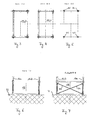
- the Fig. 1 shows a heavy-load loading system 10 according to the invention in a side view.
- the heavy duty loading system 10 is adapted to load a ship S floating in a body of water G with extremely heavy goods such as transformers, presses or power plant turbines or to clear the ship S.
- the heavy-load loading system 10 has two mutually parallel crane runway girders 16a, 16b, which may, for example, be I-girders of the IPE, HEAA, HEA, HEB or HEM series.
- the crane runway girders 16a, 16b are preferably designed as closed hollow-profile boxes with a height dimension of the order of 150 cm to 250 cm, as shown in FIG Fig. 6 to 11 can be removed.
- the heavy duty loading system 10 further comprises a first land-side support structure 12, which may for example be erected on the subsurface U of a harbor, and a second ship-side support structure 14 which extends into the hull of the ship S and stands up there.
- the two crane runway girders 16a, 16b are mounted on the first support structure 12 on the shore and on the second support structure 14 on the ship.
- each of the two crane runway girder 16a, 16b thus the static system of a single-frame carrier is based, in which both the maximum bending moment and the maximum occurring lateral force is smaller than in a cantilevered crane runway girder.
- Fig. 2 how best of all Fig. 2 can be removed, extend between the two parallel crane runway girders 16a, 16b two trolley 18 forming Katzlini 20a, 20b, which are not shown in detail on sliding or rolling means on the upper flange of the two crane runway girder 16a, 16b in the longitudinal direction of the same.
- the trolley 18 may also be formed by more or less than two cat carriers.
- the trolley 18 has a total of four synchronously operable hoists 22, which may preferably be stranded jacks, as can be lifted with such strand jacks loads of several 100 t, so that hoist 22 has no relevant influence on the maximum load capacity of the heavy load loading system 10 has.
- the two support structures 12, 14 are spatial frames with rigid and preferably concave frame corners (see, for example, FIG. Fig. 7 . Fig. 1 ), whereby not only the spatial rigidity of the support structures 12, 14 but also the maximum occurring internal internal forces, which are caused by the corner moments, can be kept small.
- the support structures 12, 14 are thus each formed by three frames, which are arranged and oriented relative to each other so that they form a U-shape in plan view, as for example the 3 and 4 can be removed.
- the mutually perpendicular frames are divided each with a common corner support.
- the support structures 12, 14 Due to the fact that the support structures 12, 14 have a U-shape in the plan view, it is possible to transport goods to be suspended on the trolley 18 or the hoists 22 in particular into the inner area of the ship-side support structure 14 and there to the ship S, which it is to be loaded, can be discontinued. Also, in this way, a discharge of the ship S is possible by goods that are located in the interior of the U-shape of the ship-side support structure 14 on the ship S, raised from there by means of the trolley 18 and the hoists 22 and out of the area the ship-side support structure 14 are conveyed out.
- both the frame panels extending in the longitudinal direction of the crane runway girders 16a, 16b and the transversely extending outer frame panels can be stiffened by bandages 24 in the form of crossing bars or ropes.
- bandages 24 in the form of crossing bars or ropes.
- only the said U-shape forming frame or their supports can be stiffened with bandages, whereas the two inner supports of the two support structures 12, 14 should not be stiffened by bandages, as this the transport of hanging on the hoists 22 Goods in the area of the land-side support structure 12 in the inner region of the ship-side support structure 14 or vice versa would be hindered.
- the ship-side support structure 14 is height-adjustable, as shown in FIG Fig. 1 indicated by the arrows H.
- This height adjustment H can be at a draft change take advantage of the ship S to the extent that the height adjustment H, the height of the support structure 14 can be increased or decreased by the same amount by which the draft of the ship S or has decreased. In this way it can be prevented that the crane runway girders 16a, 16b experience an undesired change in inclination.
- the support structure 14 in the illustrated embodiment has telescopic, preferably hydraulically telescoping supports 26 (FIG. Fig. 1 ), so that any depth changes of the ship S can be compensated continuously or in real time by actuation of associated actuation actuators (not recognizable).
- a dragonfly 28 and / or a digital spirit level 28 is provided in the area of the gantry girders 16a, 16b so as to reduce the inclination of the crane girder 16a, 16b continuously monitor respective crane runway girder 16a, 16b and, if appropriate, either manually or using a corresponding control device to cause the aforementioned actuator to vary the height of the supports 26 of the support structure 14.
- the ship-side support structure 14 consists of at least two stackable U-shaped frame modules 14.1, 14.2, wherein the upper frame module 14.2 with each the two crane runway girders 16a, 16b can be detachably connected via two strap connections 30.
- the upper frame module 14.2 can thus be attributed to a certain extent the stationary, land-side part of the heavy load loading system 10, whereas the lower frame module 14.1 can be attributed to the ship S, which allows each ship S, be with the inventive heavy-load loading system 10 be - or to be unloaded, has its own frame module 14.1 to compensate for the height difference to the lower edge of the upper frame module 14.2 can.
- the lower frame module 14.1 or its supports 26 therefore do not have to have such a large telescopic lift that the height difference can thus be bridged to the lower edge of the crane runway girders 16a, 16b.
- the two support points 30 on which each of the crane runway girders 16a, 16b rests on the support structure 14 are provided by a load balancing device such as a hydraulic coupling K interconnected so as to ensure a load balance between the support points 30. In this way it can be ensured that the support structure 14 is always uniformly loaded, whereby the risk of buckling individual supports is reduced by any overload.
- the two crane runway girders 16a, 16b are mounted on the landside support structure 12 only at a single support point 32 in the form of a monovalent support, which permits longitudinal movement of the crane run girders 16a, 16b with respect to the shore support structure 12.
- an already pre-assembled lower, ship-side frame module 14.1 can subsequently be fitted into the fuselage, for example with a mobile crane (not shown) of the ship S are lifted, if the ship S does not already have such a lower frame module 14.1 itself.
- an already preassembled second or upper frame module 14.2 is placed on the lower frame module 14.1 with the mobile crane, so that then placed on the two so constructed support structures 12, 14 with the help of the mobile crane, the two crane runway girder 16a, 16b in the manner explained above or can be stored.
- the unit consisting of gantry girders 16a, 16b and upper frame module 14.2 can also be brought into position as a whole with the aid of the mobile crane. After finally the trolley 18 with the mobile crane on the two crane runway girders 16a, 16b was discontinued, then the operation of the heavy duty loading system 10 can be recorded.
- a heavy load loading system is proposed for the first time, which at least partially discharges its loads to a ship to be loaded or unloaded.
Landscapes
- Chemical & Material Sciences (AREA)
- Engineering & Computer Science (AREA)
- Combustion & Propulsion (AREA)
- Mechanical Engineering (AREA)
- Ocean & Marine Engineering (AREA)
- Ship Loading And Unloading (AREA)
Abstract
Description
Die vorliegende Erfindung betrifft ein Schwerlast-Verladesystem sowie ein Verfahren zum Be- und/oder Entladen von Schiffen.The present invention relates to a heavy load loading system and a method for loading and / or unloading of ships.
Zum Be- und Entladen von Schiffen kommen häufig Portalkrane zum Einsatz, welche einen frei auskragenden Kranbahnträger aufweisen, der sich bis über das zu beladende Schiff erstreckt, um die zu verladenden Güter auf das Schiff absenken oder von dort anheben zu können. Obwohl mit derartigen Portalkranen verhältnismäßig große Lasten bewegt werden können, ist die maximale Traglast dieser Portalkrane dennoch unter anderem durch die Kragarmlänge des frei auskragenden Kranbahnträgers begrenzt.For loading and unloading of ships often portal cranes are used, which have a cantilevered crane runway carrier, which extends beyond the ship to be loaded in order to lower the goods to be loaded on the ship or lift from there. Although relatively large loads can be moved with such gantry cranes, the maximum load of these gantry cranes is nevertheless limited, inter alia, by the Kragarmlänge the cantilevered crane runway girder.
Darüber hinaus wird die maximale Traglast bekannter Schiffskrane auch dadurch begrenzt, dass diese sowohl ihr Eigengewicht als auch das der zu bewegenden Güter in den Untergrund ableiten, auf welchem sie errichtet sind. Somit beeinflusst auch die Tragfähigkeit des Untergrunds und insbesondere der Grundbruchwiderstand maßgeblich die maximale Traglast bekannter Schiffskrane, was zur Folge hat, dass extrem schwere Lasten wie beispielsweise Transformatoren, Pressen oder Kraftwerksturbinen mit herkömmlichen Schiffskranen nicht oder nur unter Anwendung von Hilfsmaßnahmen wie beispielsweise zusätzlicher Krane bewegt werden können.In addition, the maximum load of known ship cranes is also limited by the fact that they derive both their own weight and that of the goods to be moved into the ground on which they are built. Thus, the bearing capacity of the subsurface and in particular the Grundbruchwiderstand significantly affects the maximum load of known ship cranes, with the result that extremely heavy loads such as transformers, presses or power turbine turbines are not moved with conventional ship cranes or only with the help of auxiliary measures such as additional cranes can.
Der Erfindung liegt daher die Aufgabe zugrunde ein Schwerlast-Verladesystem sowie ein Verfahren zum Be- und/oder Entladen von Schiffen zu schaffen, um auch extrem schwere Lasten wie beispielsweise Transformatoren, Pressen oder Kraftwerksturbinen bewegen zu können.The invention is therefore based on the object of a heavy load loading system and a method for loading and / or unloading of ships to move even extremely heavy loads such as transformers, presses or power plant turbines.
Diese Aufgabe wird gemäß einem Aspekt der vorliegenden Erfindung mit einem Schwerlast-Verladesystem zum Be- und/oder Entladen von Schiffen gelöst, das die Merkmale des Anspruchs 1 aufweist.This object is achieved according to one aspect of the present invention with a heavy duty loading system for loading and / or unloading ships, having the features of
Das erfindungsgemäße Schwerlast-Verladesystem weist zumindest einen Kranbahnträger auf, an dem entlang eine ein Hebezeug aufweisende Laufkatze bis über das zu be- und/oder entladende Schiff verfahrbar ist, wobei der zumindest eine Kranbahnträger auf einer ersten Stützkonstruktion landseitig und auf einer zweiten Stützkonstruktion schiffseitig, die sich auf dem zu be- und/oder entladenden Schiff befindet, gelagert ist.The heavy-duty loading system according to the invention has at least one crane runway girder along which a lifting trolley can be moved beyond the ship to be loaded and / or unloaded, the at least one gantry girder on a first support structure on the shore side and on a second support structure on the ship side, which is located on the loading and / or unloading ship is stored.
Erfindungsgemäß wird somit erstmals vorgeschlagen, für den üblicherweise frei auskragenden Kranbahnträger ein zweites Auflager zu schaffen, welches sich auf dem zu be- und/oder entladenden Schiff befindet und welches somit das üblicherweise frei auskragende Ende des Kranbahnträgers unter- bzw. abstützt. Das Gewicht des Kranbahnträgers selbst sowie das Gewicht der zu bewegenden Güter wird somit anteilig über die landseitige Stützkonstruktion in den Untergrund und über die schiffseitige Stützkonstruktion in das Schiff abgeleitet, womit die Grundbruchgefahr des Untergrunds, auf dem die erste landseitige Stützkonstruktion steht, verringert wird. Darüber hinaus werden durch die Auflagerung des Kranbahnträgers auf der schiffseitigen Stützkonstruktion das in dem Kranbahnträger maximal auftretende Biegemoment sowie die maximal auftretende Querkraft reduziert, so dass mit im wesentlichen gleich dimensionierten Kranbahnträgern deutlich schwerere Lasten bewegt werden können.According to the invention, it is thus proposed for the first time to provide a second support for the usually cantilevered crane runway girder, which is located on the ship to be loaded and / or unloaded and thus supports or supports the usually freely projecting end of the gantry support. The weight of the crane runway girder itself as well as the weight of the goods to be moved is thus proportionately derived via the shore-side support structure into the ground and the ship-side support structure in the ship, whereby the Grundbruchgefahr the substrate on which the first land-side support structure is reduced. In addition, the maximum bending moment occurring in the crane runway carrier as well as the maximum occurring transverse force are reduced by the bearing of the crane runway girder on the ship-side support structure, so that significantly heavier loads can be moved with essentially the same sized crane runway girders.
Um die Laufkatze bis über das zu be- und/oder entladende Schiff verfahren zu können, um dort Güter abladen oder aufnehmen zu können, ist die schiffseitige Stützkonstruktion derart ausgebildet ist, dass mit dem Schwerlast-Verladesystem zu verladende Güter an dem Hebezeug hängend bis in den inneren Bereich der Stützkonstruktionen beförderbar sind. Hierzu kann die schiffseitige Stützkonstruktion beispielsweise einen U-förmigen Grundriss aufweisen, da hierdurch sichergestellt werden kann, dass zu verladende Güter an dem Hebezeug hängend durch die Öffnung des "U" bis in den inneren Bereich der Stützkonstruktionen befördert werden können.In order to be able to move the trolley up to about the loading and / or unloading ship to unload or pick up goods there, the ship-side support structure is designed such that with the heavy load loading system to be loaded goods hanging on the hoist up in the inner region of the support structures are conveyed. For this purpose, the ship-side support structure, for example, have a U-shaped plan, as this can ensure that goods to be loaded on the hoist hanging through the opening of the "U" can be transported into the inner region of the support structures.
Bevorzugte Ausführungsformen des erfindungsgemäßen Schwerlast-Verladesystems ergeben sich aus der Beschreibung, den Zeichnungen sowie den abhängigen Systemansprüchen.Preferred embodiments of the heavy duty loading system according to the invention will become apparent from the description, the drawings and the dependent system claims.
Um besonders schwere Lasten bewegen zu können, kann das erfindungsgemäße Schwerlast-Verladesystem gemäß einer bevorzugten Ausführungsform zwei parallel zueinander verlaufende Kranbahnträger aufweisen, die beide landseitig auf der ersten Stützkonstruktion und schiffseitig auf der zweiten Stützkonstruktion gelagert sind. Das Gewicht der zu bewegenden Lasten wird somit, bevor es in die beiden Stützkonstruktionen eingeleitet wird, auf zwei Kranbahnträger aufgeteilt, so dass jeder der beiden Kranbahnträger nochmals weniger Biegemoment und Querkraft erfährt, was im Umkehrschluss eine Steigerung der maximalen Traglast bedeutet. Darüber hinaus reduzieren sich dadurch, dass zwei Kranbahnträger zum Einsatz kommen, auch die Auflagerkräfte des jeweiligen Kranbahnträgers auf den Stützkonstruktionen und damit auch die Schnittgrößen, die zur Dimensionierung der Auflager und der Knotenpunkte zwischen Kranbahnträger und Stützkonstruktion maßgeblich werden, wodurch nicht nur die einzelnen Kranbahnträger sondern auch die jeweiligen Auflager geringer dimensioniert werden können.In order to be able to move particularly heavy loads, the heavy-duty loading system according to the invention may comprise two mutually parallel crane runway girders, both of which are mounted on the land side on the first support structure and on the ship side on the second support structure. The weight of the loads to be moved is thus, before it is introduced into the two support structures, split on two crane runway beams, so that each of the two crane runway again undergoes less bending moment and shear force, which means inversely an increase in the maximum load. In addition, the fact that two crane runway carriers are used also reduces the bearing forces of the respective crane runway carrier on the supporting structures and thus also the internal forces that are decisive for dimensioning the supports and the intersections between the crane runway girder and the supporting structure individual crane runway beams but also the respective supports can be dimensioned smaller.
Damit das Gewicht der zu bewegenden Lasten möglichst gleichmäßig auf die beiden Kranbahnträger aufgeteilt wird, kann das erfindungsgemäße Schwerlast-Verladesystem gemäß einer weiteren Ausführungsform zumindest einen, vorzugsweise zwei gemeinsam entlang der Kranbahnträger verfahrbare Katzträger aufweisen, welche den Abstand zwischen den beiden Kranbahnträgern überspannen.In order that the weight of the loads to be moved is divided as evenly as possible on the two crane runway carriers, the heavy load loading system according to the invention can comprise at least one, preferably two, cat carriers which can be moved together along the crane runway carriers, which span the distance between the two crane runway carriers.
Gemäß einer weiteren Ausführungsform kann/können an jedem der Katzträger zumindest ein, vorzugsweise zwei Hebezeuge vorgesehen sein, bei denen es sich beispielsweise um Seil- oder Kettenzüge oder Seil- oder Kettenwinden handeln kann. Besonders vorteilhaft erweist es sich jedoch, wenn als Hebezeuge sogenannte Litzenheber zum Einsatz kommen, da mit derartigen Litzenhebern Lasten von mehreren 100 t gehoben werden können, so dass das Hebezeug keinerlei relevanten Einfluss auf die maximale Tragfähigkeit des Schwerlast-Verladesystems hat.According to a further embodiment, at least one, preferably two hoists may be provided on each of the cat carriers, which may be, for example, cable or chain hoists or rope or chain winches. However, it proves to be particularly advantageous if so-called strand jacks are used as hoists, since loads of several 100 t can be lifted with such strand jacks, so that the hoist has no relevant influence on the maximum load capacity of the heavy-load loading system.
Obwohl sich das erfindungsgemäße Schwerlast-Verladesystem zum Bewegen extrem schwerer Lasten eignet, wird sich in aller Regel der Tiefgang des mit dem erfindungsgemäßen Schwerlast-Verladesystem zu be- und/oder entladende Schiff nicht oder nur geringfügig ändern, da der Auftrieb des Schiffes in aller Regel um ein Vielfaches größer sein wird, als die zu bewegenden Lasten. Das jeweilige Schiff kann somit gewissermaßen als unendlich starres Auflager betrachtet werden, an das die schiffseitige Stützkonstruktion seine Lasten abgibt.Although the heavy-duty loading system according to the invention is suitable for moving extremely heavy loads, the draft of the ship loading and / or unloading with the heavy-duty loading system according to the invention will generally not change or will only change slightly, since the buoyancy of the ship is generally high will be many times greater than the loads to be moved. The respective ship can thus be regarded as a kind of infinite rigid support to which the ship-side support structure releases its loads.
Im Falle, dass sich jedoch der Tiefgang des Schiffs dennoch während des Be- und/oder Entladevorgangs ändern sollte, was beispielsweise bei kleineren Schiffen oder bei der Beladung mit einer Vielzahl von extrem schweren Gütern der Fall sein kann, ist es gemäß einer weiteren Ausführungsform vorgesehen, dass die erste Stützkonstruktion und/oder die zweite Stützkonstruktion zum Ausgleich lastbedingter Neigungsänderungen des Kranbahnträgers höhenverstellbar ausgebildet sind, wozu die erste Stützkonstruktion und/oder die zweite Stützkonstruktion teleskopierbare, vorzugsweise hydraulisch teleskopierbare Stützen aufweisen kann. Wenn sich nämlich der Tiefgang des zu beladenden Schiffes während des Beladevorgangs ändern sollte, so wirkt sich diese Tiefgangänderung infolge der Lagerung des Kranbahnträgers über die zweite schiffseitige Stützkonstruktion auf die Neigung des Kranbahnträgers aus. Da derartige Neigungsänderungen jedoch grundsätzlich unerwünscht sind, da sie beispielsweise zu extrem hohen Zwangsspannungen in dem Kranbahnträger führen können, kann beispielsweise im Falle, dass der Tiefgang des Schiffes um ein gewisses Maß zunehmen sollte, die Stützhöhe der zweiten, schiffseitigen Stützkonstruktion um dasselbe Maß vergrößert werden, um die der Tiefgang zunimmt, so dass der Kranbahnträger erst gar keine Neigungsänderung erfährt.In the case, however, that the draft of the ship should nevertheless change during the loading and / or unloading, which, for example, in smaller Ships or when loading with a variety of extremely heavy goods may be the case, it is provided according to a further embodiment, that the first support structure and / or the second support structure to compensate for load-induced inclination changes of the crane runway carrier are adjustable in height, including the first support structure and / or the second support structure can have telescopic, preferably hydraulically telescopic supports. If, in fact, the draft of the ship to be loaded should change during the loading process, this draft change has an effect on the inclination of the crane runway girder as a result of the bearing of the crane runway girder via the second ship-side support structure. However, since such changes in inclination are generally undesirable, since they can lead to extremely high forced voltages in the crane runway girder, for example, in the event that the draft of the ship should increase to a certain extent, the support height of the second, ship-side support structure can be increased by the same amount around which the draft increases, so that the crane runway carrier does not experience any change in inclination.
Da jedoch die in Rede stehenden Neigungsänderungen des/der Kranbahnträger mit dem bloßen Auge nicht oder nur kaum erkennbar sind und schon bereits geringste Neigungsänderungen extrem hohe Zwangspannungen in dem/den Kranbahnträgern hervorrufen können, ist es gemäß einer weiteren Ausführungsform vorgesehen, dass im Bereich zumindest eines Kranbahnträgers ein Sensor, z. B. eine Libelle oder eine digitale Wasserwaage, vorgesehen ist, der die Neigung des jeweiligen Kranbahnträgers misst. Durch kontinuierliche Überwachung des Messergebnisses der Libelle oder der digitalen Wasserwaage kann somit eine Entscheidung darüber getroffen werden, ob und welche der beiden Stützkonstruktionen in ihrer Höhe zu verstellen ist.However, since the changes in inclination of the crane runway girder (s) with the naked eye are barely discernible, and even slightest changes in inclination can cause extremely high forced stresses in the gantry crane (s), it is provided according to a further embodiment that in the area at least one Crane rail carrier a sensor, z. As a dragonfly or a digital spirit level, is provided which measures the inclination of the respective crane runway girder. By continuously monitoring the measurement result of the dragonfly or the digital spirit level, a decision can therefore be made as to whether and which of the two support structures is to be adjusted in height.
Obwohl diese Höhen- bzw. Neigungsjustierung manuell vorgenommen werden kann, indem eine Bedienperson kontinuierlich das Messergebnis der Libelle oder digitalen Wasserwaage überwacht und gegebenenfalls aktiv eine Höhenverstellung der jeweiligen Stützkonstruktion vornimmt, kann gemäß einer weiteren Ausführungsform diese Justierung auch automatisch erfolgen. Hierzu kann das erfindungsgemäße Schwerlast-Verladesystem gemäß einer weiteren Ausführungsform eine Regelungseinrichtung umfassen, welche unter Auswertung der Kranbahnträgerneigung kontinuierlich die Höhe der ersten Stützkonstruktion und/oder der zweiten Stützkonstruktion verändert. Die Regelungseinrichtung wertet dabei beispielsweise die von der digitalen Wasserwaage erzeugten Messergebnisse aus und erzeugt entsprechende Steuersignale, durch die ein Aktuator zur Verstellung der Höhe der jeweiligen Stützkonstruktion dazu veranlasst werden kann, die gewünschte Höhenverstellung vorzunehmen.Although this height or inclination adjustment can be made manually by an operator continuously monitors the measurement result of Libelle or digital spirit level and optionally actively makes a height adjustment of the respective support structure, according to a further embodiment, this adjustment can also be done automatically. For this purpose, the heavy-duty loading system according to the invention may comprise a control device according to another embodiment, which continuously changes the height of the first support structure and / or the second support structure, evaluating the Kranbahnträgerneigung. The control device evaluates, for example, the measurement results generated by the digital spirit level and generates corresponding control signals, by which an actuator for adjusting the height of the respective support structure can be made to make the desired height adjustment.
Gemäß einer weiteren Ausführungsform kann die zweite bzw. die schiffseitige Stützkonstruktion zumindest zwei übereinander stapelbare Module umfassen, wobei das obere Modul vorzugsweise lösbar mit dem zumindest einem Kranbahnträger verbunden ist. Diese Ausführungsform kann sich insbesondere dann als vorteilhaft erweisen, wenn mit dem erfindungsgemäßen Schwerlast-Verladesystem unterschiedliche und insbesondere unterschiedlich große Schiffe beladen werden sollen, da hierzu je nach Schiffsgröße und Aufbau unterschiedlich hohe schiffseitige Stützkonstruktionen benötigt werden. Anstelle jedoch auf jedem mit dem erfindungsgemäßen Schwerlast-Verladesystem zu beladenden Schiff unterschiedlich hohe schiffseitige Stützkonstruktionen zu schaffen, erlaubt es die in Rede stehende Ausführungsform, bei der die schiffseitige Stützkonstruktion zumindest zwei übereinander stapelbare Module umfasst, dass lediglich das untere Modul, in unterschiedlich hohen Ausführungsformen vorgehalten werden muss, um die Höhendifferenz bis zur Unterkante des oberen Moduls zu überbrücken. Die schiffseitige Stützkonstruktion in zumindest zwei übereinander stapelbare Module zu untergliedern, erweist sich somit dahingehen als vorteilhaft, dass beispielsweise das untere Modul fester Bestandteil des jeweiligen Schiffs sein kann, so dass dieses untere Modul gewissermaßen als Adapter zur Koppelung an das erfindungsgemäße Schwerlast-Verladesystem angesehen werden kann.According to a further embodiment, the second or the ship-side support structure may include at least two stackable modules, wherein the upper module is preferably releasably connected to the at least one crane runway girder. This embodiment may prove to be advantageous in particular when different and in particular different sized ships are to be loaded with the heavy-duty loading system according to the invention since, depending on the size of the ship and the structure, different levels of support structures on the ship are required. However, instead of creating differently high ship-side support structures on each ship to be loaded with the heavy-load loading system of the present invention, the present embodiment allows the ship-side support structure to comprise at least two stackable modules, only the lower module, in different high embodiments must be maintained in order to bridge the height difference to the lower edge of the upper module. The ship-side support structure in at least two stackable modules to subdivide, thus turns out to be advantageous that, for example, the lower module can be an integral part of the ship, so that this lower module are effectively regarded as an adapter for coupling to the heavy-load loading system according to the invention can.
Wie bereits zuvor erläutert wurde, können bereits geringe Verformungen des/der Kranbahnträger extrem hohe Zwangsspannungen in dem betroffenen Kranbahnträger hervorrufen. Dementsprechend weist der jeweilige Kranbahnträger nur einen einzigen Auflagerpunkt an der landseitigen Stützkonstruktion auf, um zu verhindern, dass unerwünschte Zwangsspannungen in den jeweiligen Kranbahnträger eingeleitet werden, welche durch eine Mehrfachlagerung entstehen können. Der jeweilige Kranbahnträger kann sich somit lastbedingt geringfügig durchbiegen, ohne dass hierbei Zwangsschnittgrößen auftreten, wie dies bei statisch überbestimmten System der Fall sein kann.As already explained above, even slight deformations of the crane runway girder (s) can cause extremely high forced stresses in the affected crane runway girder. Accordingly, the respective crane runway carrier only a single support point on the shore-side support structure in order to prevent unwanted forced voltages are introduced into the respective crane runway carrier, which can be caused by a multiple storage. The respective crane runway girder can thus slightly deflect due to the load, without any forced-cut sizes occurring, as may be the case with statically overdetermined systems.
Gemäß einer besonders bevorzugten Ausführungsform kann es dabei ferner vorgesehen sein, dass das Auflager, an dem der zumindest eine Kranbahnträger auf der ersten Stützkonstruktion gelagert ist, ein einwertiges, in Längsrichtung des zumindest einen Kranbahnträgers verschiebliches Lager ist. Auf dieser Weise können nicht nur temperaturbedingte Normakraftspannungen sondern auch solche Normalkraftspannungen verhindert werden, die durch seitliche Bewegungen des zu belandenden Schiffes ansonsten in den Kranbahnträger eingeleitet werden würden.According to a particularly preferred embodiment, it can further be provided that the support, on which the at least one crane runway support is mounted on the first support structure, is a monovalent bearing displaceable in the longitudinal direction of the at least one crane runway support. In this way, not only temperature-induced Normakraftspannungen but also such normal force voltages can be prevented, which would otherwise be initiated by lateral movements of the vessel to be loaded in the crane runway carrier.
Um die schiffseitige Stützkonstruktion auch bei geringfügigen Rollbewegungen des Schiffs stets gleichmäßig zu belasten, ist es gemäß einer weiteren bevorzugten Ausführungsform vorgesehen, dass jeder Kranbahnträger an zwei Auflagern auf der zweiten Stützkonstruktion gelagert und vorzugsweise lösbar mit dieser verbunden ist, wobei eine Lastausgleichseinrichtung, vorzugsweise eine hydraulische Koppelung vorgesehen ist, die selbsttätig einen Lastausgleich zwischen den Auflagern vornimmt, an denen der jeweilige Kranbahnträger auf der zweiten Stützkonstruktion gelagert ist.In order to load the ship-side support structure even with minor rolling movements of the ship always evenly, it is according to another provided preferred embodiment that each crane runway carrier is mounted on two supports on the second support structure and preferably releasably connected thereto, wherein a load balancing device, preferably a hydraulic coupling is provided which automatically performs load balancing between the supports on which the respective crane runway carrier on the second support structure is stored.
So würde beispielsweise eine geringfügige Rollbewegung des Schiffes normalerweise dazu führen, dass das eine Auflager entlastet und dafür das andere Auflager zusätzlich belastet wird. Solch einer ungleichmäßigen Auflagerbelastung kann durch eine hydraulische Koppelung der einzelnen Auflager entgegengewirkt werden, da diese dafür sorgt, dass jedes Auflager stets gleich belastet ist. Dies kann beispielsweise dadurch erreicht werden, dass jedes Auflager eine Kolbenzylindereinheit umfasst, welche miteinander in Fluidverbindung stehen, wodurch belastungsbedingte Verformungen des einen Lagers in entsprechend entgegengesetzte Verformungen des anderen Lagers umgesetzt werden können, was einem Lastausgleich zwischen den jeweiligen Lagern entspricht.Thus, for example, a slight rolling movement of the ship would normally lead to relieving the one bearing and additionally burdening the other abutment. Such an uneven Auflagerbelastung can be counteracted by a hydraulic coupling of the individual supports, as this ensures that each support is always charged equally. This can for example be achieved in that each support comprises a piston-cylinder unit, which are in fluid communication with each other, whereby load-induced deformations of the one bearing can be converted into corresponding opposite deformations of the other bearing, which corresponds to a load balance between the respective camps.
Gemäß einem weiteren Aspekt der vorliegenden Erfindung wird die der Erfindung zugrunde liegende Aufgabe auch mit einem Verfahren zum Be- und/oder Entladen von Schiffen gelöst, welches die Merkmale des Anspruchs 13 aufweist. Der Vollständigkeit halber sei an dieser Stelle angemerkt, dass sich sämtliche Merkmale des erfindungsgemäßen Schwerlast-Verladesystems bei dem erfindungsgemäßen Verfahren implementieren lassen, da dieses vorzugsweise unter Verwendung des erfindungsgemäßen Schwerlast-Verladesystems arbeitet.According to a further aspect of the present invention, the object underlying the invention is also achieved with a method for loading and / or unloading ships, which has the features of claim 13. For the sake of completeness, it should be noted at this point that all the features of the heavy duty loading system according to the invention can be implemented in the method according to the invention, since this preferably operates using the heavy load loading system according to the invention.
Das erfindungsgemäße Verfahren zum Be- und/oder Entladen von Schiffen läuft so ab, dass zunächst eine landseitige Stützkonstruktion und eine schiffseitige Stützkonstruktion, die sich auf dem zu be- und/oder entladenden Schiff befindet, geschaffen werden, auf denen dann zumindest ein Kranbahnträger gelagert wird. Anschließend werden dann zu verladende Güter unter Verwendung einer ein Hebezeug aufweisenden Laufkatze, die entlang des zumindest einen Kranbahnträger verfahrbar ist, verladen.The inventive method for loading and / or unloading of ships runs so that first a land-side support structure and a ship-side support structure, which is located on the loading and / or unloading ship, are created on which then stored at least one crane runway becomes. Subsequently, goods to be loaded are then loaded using a trolley having a hoist, which is movable along the at least one crane runway carrier.
Bevorzugte Ausführungsformen des erfindungsgemäßen Verfahrens zum Be- und/oder Entladen von Schiffen ergeben sich aus der Beschreibung, den Zeichnungen sowie den abhängigen Verfahrensansprüchen.Preferred embodiments of the method according to the invention for loading and / or unloading ships result from the description, the drawings and the dependent method claims.
Um während des Verladevorgangs die Entstehung verformungsbedingter Zwangsspannungen in dem Kranbahnträger zu vermeiden, ist es gemäß einer bevorzugten Ausführungsform des erfindungsgemäßen Verfahrens vorgesehen, während des Verladevorgangs kontinuierlich die Kranbahnträgerneigung zu überwachen, wobei im Falle, dass die Kranbahnträgerneigung einen vorbestimmten Schwellwert über- oder unterschreiten sollte, die Kranbahnträgerneigung aktiv verändert wird, indem vorzugsweise die Höhe der schiffseitigen Stützkonstruktion und/oder der landseitigen Stützkonstruktion verändert wird. Dies kann beispielsweise dadurch erfolgen, dass eine Bedienperson kontinuierlich die Kranbahnträgerneigung unter Verwendung eines daran angebrachten Sensors, z. B. einer Libelle oder digitalen Wasserwaage, überwacht. Sollte die Bedienperson hierbei feststellen, dass die Kranbahnträgerneigung einen vorbestimmten Schwellwert über- oder unterschreitet, so kann die Bedienperson einen Betätigungsaktuator wie beispielsweise eine hydraulische Pumpe aktivieren, um damit die Stützen der betroffenen Stützkonstruktion hydraulisch ein oder aus zu teleskopieren, wozu im Bereich der Stützen entsprechende Kolben-Zylindereinheiten anzuordnen sind.In order to avoid the emergence of deformation-induced positive stresses in the crane runway during the loading process, it is provided according to a preferred embodiment of the method according to the invention during the loading process to continuously monitor the crane runway inclination, wherein in case that the crane runway slope should exceed or fall below a predetermined threshold, the crane track carrier inclination is actively changed by preferably changing the height of the ship-side support structure and / or the shore-side support structure. This can be done, for example, that an operator continuously crane runner inclination using a sensor attached thereto, for. As a dragonfly or digital spirit level, monitored. If the operator determines that the crane runway inclination exceeds or falls below a predetermined threshold value, the operator can activate an actuation actuator, such as a hydraulic pump, to hydraulically telescope in or out the supports of the affected support structure, for example in the area of the supports Piston-cylinder units are to be arranged.
Im Folgenden werden das erfindungsgemäße Schwerlast-Verladesystem und das erfindungsgemäße Verfahren rein beispielhaft anhand einer exemplarischen Ausführungsform unter Bezugnahme auf die beigefügten Zeichnungen beschrieben, wobei:
- Fig. 1
- eine Aufrissdarstellung des erfindungsgemäßen Schwerlast- Verladesystems zeigt;
- Fig. 2
- eine Draufsicht auf das erfindungsgemäße Schwerlast- Verladesystems der
Fig. 1 zeigt; - Fig. 3
- den Schnitt A - A der
Fig. 1 zeigt; - Fig. 4
- den Schnitt B - B der
Fig. 1 zeigt; - Fig. 5
- den Schnitt C - C der
Fig. 1 zeigt; - Fig. 6
- den Schnitt F - F der
Fig. 1 zeigt; - Fig. 7
- den Schnitt H - H der
Fig. 1 zeigt; - Fig. 8
- den Schnitt G - G der
Fig. 1 zeigt; - Fig. 9
- den Schnitt E - E der
Fig. 1 zeigt; - Fig.
- 10 den Schnitt D - D der
Fig. 1 zeigt; und - Fig. 11
- den Schnitt I - I der
Fig. 1 zeigt.
- Fig. 1
- an elevation view of the heavy duty loading system according to the invention;
- Fig. 2
- a plan view of the heavy-load loading system of the invention
Fig. 1 shows; - Fig. 3
- the section A - A of
Fig. 1 shows; - Fig. 4
- the section B - B of the
Fig. 1 shows; - Fig. 5
- the section C - C of the
Fig. 1 shows; - Fig. 6
- the section F - F of
Fig. 1 shows; - Fig. 7
- the section H - H the
Fig. 1 shows; - Fig. 8
- the section G - G of the
Fig. 1 shows; - Fig. 9
- the cut E - E the
Fig. 1 shows; - FIG.
- 10 the section D - D the
Fig. 1 shows; and - Fig. 11
- the section I - I the
Fig. 1 shows.
Die
Das erfindungsgemäße Schwerlast-Verladesystem 10 umfasst ferner eine erste landseitige Stützkonstruktion 12, die beispielsweise auf dem Untergrund U eines Hafen errichtet sein kann, sowie eine zweite schiffseitige Stützkonstruktion 14, die sich in den Rumpf des Schiffs S hineinerstreckt und darin aufsteht. Die beiden Kranbahnträger 16a, 16b sind dabei auf der ersten Stützkonstruktion 12 landseitig und auf der zweiten Stützkonstruktion 14 schiffseitig gelagert.The heavy
Sofern die landseitige Stützkonstruktion 12 und die schiffseitige Stützkonstruktion 14 global betrachtet als Einzelauflager für die beiden Kranbahnträger 16a, 16b betrachtet werden, liegt jedem der beiden Kranbahnträger 16a, 16b somit das statische System eines Einfeldträgers zugrunde, bei dem sowohl das maximale Biegemoment als auch die maximal auftretende Querkraft kleiner ist als bei einem frei auskragenden Kranbahnträger. Im Umkehrschluss bedeutet dies, dass bei gleich groß dimensionierten Kranbahnträgern mit dem erfindungsgemäßen Schwerlast-Verladesystem 10 deutlich schwerere Lasten gehoben und bewegt werden können, als mit einem Portalkran mit gleich groß dimensionierten, frei auskragenden Kranbahnträgern.If the shore-
Wie am besten der
In der dargestellten Ausführungsform weist die Laufkatze 18 insgesamt vier synchron betätigbare Hebezeuge 22 auf, bei denen es sich vorzugsweise um Litzenheber handeln kann, da mit derartigen Litzenhebern Lasten von mehreren 100 t gehoben werden können, so dass Hebezeug 22 keinerlei relevanten Einfluss auf die maximale Tragfähigkeit des Schwerlast-Verladesystems 10 hat.In the illustrated embodiment, the
Bei den beiden Stützkonstruktionen 12, 14 handelt es sich um räumliche Rahmen mit biegesteifen und vorzugsweise gevouteten Rahmenecken (siehe bspw.
Um die räumliche Steifigkeit der Stützkonstruktionen 12, 14 weiter zu erhöhen, können sowohl die sich in Längsrichtung der Kranbahnträger 16a, 16b erstreckenden Rahmenfelder als auch die sich in Querrichtung erstreckenden äußeren Rahmenfelder durch Verbände 24 in Form von sich kreuzenden Stäben oder Seilen ausgesteift sein. Grundsätzlich können dabei nur die die genannte U-Form bildenden Rahmen bzw. deren Stützen mit Verbänden ausgesteift werden, wohingegen die beiden innen liegenden Stützen der beiden Stützkonstruktionen 12, 14 nicht durch Verbände ausgesteift werden sollten, da hierdurch der Transport von an den Hebezeugen 22 hängenden Gütern von im Bereich der landseitigen Stützkonstruktion 12 in den inneren Bereich der schiffseitigen Stützkonstruktion 14 oder umgekehrt behindert werden würde.In order to further increase the spatial rigidity of the supporting
Da es bei kleineren Schiffen S infolge der Beladung mit sehr schweren Gütern zu einer Tiefgangänderung kommen kann, ist es in der dargestellten Ausführungsform vorgesehen, dass die schiffseitige Stützkonstruktion 14 höhenverstellbar ist, wie dies in der
Um diese Höhenverstellbarkeit H zu realisieren, weist die Stützkonstruktion 14 in der dargestellten Ausführungsform teleskopierbare vorzugsweise hydraulisch teleskopierbare Stützen 26 auf (
Da jedoch weder die Tiefgangsänderungen des Schiffs S noch die dadurch einhergehenden Neigungsänderungen der Kranbahnträger 16a, 16b mit bloßem Auge erfasst werden können, ist im Bereich der Kranbahnträger 16a, 16b eine Libelle 28 und/oder eine digitale Wasserwaage 28 vorgesehen, um so die Neigung des jeweiligen Kranbahnträgers 16a, 16b kontinuierlich überwachen und gegebenenfalls entweder manuell oder unter Verwendung einer entsprechenden Regelungseinrichtung den zuvor erwähnten Aktuator dazu zu veranlassen, die Höhe der Stützen 26 der Stützkonstruktion 14 zu variieren.However, since neither the draft changes of the ship S nor the concomitant changes in inclination of the
Da unterschiedliche Schiffe, die es mit dem erfindungsgemäßen Schwerlast-Verladesystem 10 zu beladen gilt, auch unterschiedlich große Tiefgänge aufweisen können, ist es bei der dargestellten Ausführungsform ferner vorgesehen, dass sich die schiffseitige Stützkonstruktion 14 aus zumindest zwei übereinander stapelbaren U-förmigen Rahmenmodulen 14.1, 14.2 zusammensetzt, wobei das obere Rahmenmodul 14.2 mit jedem der beiden Kranbahnträger 16a, 16b über zwei Laschenverbindungen 30 lösbar verbunden sein kann. Das obere Rahmenmodul 14.2 kann somit gewissermaßen dem stationären, landseitigen Teil des Schwerlast-Verladesystems 10 zugerechnet werden, wohingegen das untere Rahmenmodul 14.1 dem Schiff S zugerechnet werden kann, was es ermöglicht, dass jedes Schiff S, das mit dem erfindungsgemäßen Schwerlast-Verladesystem 10 be- oder entladen werden soll, sein eigenes Rahmenmodul 14.1 aufweist, um die Höhendifferenz bis zur Unterkante des oberen Rahmenmoduls 14.2 ausgleichen zu können. Das untere Rahmenmodul 14.1 bzw. dessen Stützen 26 müssen daher keinen so großen Teleskophub aufweisen, das damit die Höhendifferenz bis zur Unterkante der Kranbahnträger 16a, 16b überbrückt werden kann.Since different ships, which are to be loaded with the heavy-
Um die schiffseitige Stützkonstruktion 14 auch bei geringfügigen Rollbewegungen des Schiffs S gleichmäßig mit Lasten aus den Kranbahnträgern 16a, 16b zu belasten, sind die beiden Auflagerpunkte 30, an denen jeder der Kranbahnträger 16a, 16b auf der Stützkonstruktion 14 aufliegt, durch eine Lastausgleichseinrichtung wie beispielsweise eine hydraulische Kopplung K untereinander verbunden um so einen Lastausgleich zwischen den Auflagerpunkten 30 zu gewährleisten. Auf diese Weise kann sichergestellt werden, dass die Stützkonstruktion 14 stets gleichmäßig belastet ist, wodurch die Knickgefahr einzelner Stützen durch eine etwaige Überbelastung reduziert wird.In order to evenly load the ship-
Im Unterschied zu der schiffseitigen Stützkonstruktion 14 sind die beiden Kranbahnträger 16a, 16b auf der landseitigen Stützkonstruktion 12 nur jeweils an einem einzigen Auflagerpunkt 32 in Form eines einwertigen Auflagers gelagert, welches eine Längsbewegung der Kranbahnträger 16a, 16b in Bezug auf die landseitige Stützkonstruktion 12 zulässt. Dies wird dadurch ermöglicht, dass die beiden Kranbahnträgern 16a, 16b in einer Art Köcher 34 geführt werden, welche sowohl die Kranbahnträgern 16a, 16b als auch die sich parallel dazu erstreckenden Riegel 36 der Stützkonstruktion 12 beflanken (s.
Im Folgenden werden nun die erforderlichen Schritte zum Aufbau und Betrieb des erfindungsgemäßen Schwerlast-Verladesystems erläutert:In the following, the steps required for setting up and operating the heavy-duty loading system according to the invention will now be explained:
Nachdem auf dem Hafenuntergrund U die zuvor bereits im Detail erläuterte landseitige Stützkonstruktion 12 errichtet wurde und ein Schiff S benachbart zu der landseitigen Stützkonstruktion 12 angelegt hat, kann anschließend beispielsweise mit einem Mobilkran (nicht gezeigt) ein bereits vormontiertes unteres, schiffseitiges Rahmenmodul 14.1 in den Rumpf des Schiffes S gehoben werden, sofern das Schiff S nicht bereits selbst solch ein unteres Rahmenmodul 14.1 aufweist. Anschließend wird dann mit dem Mobilkran ein bereits vormontiertes zweites bzw. oberes Rahmenmodul 14.2 auf dem unteren Rahmenmodul 14.1 abgesetzt, so dass anschließend auf den beiden so errichteten Stützkonstruktionen 12, 14 mit Hilfe des Mobilkrans die beiden Kranbahnträger 16a, 16b in der zuvor erläuterten Weise abgelegt bzw. gelagert werden können. Im Falle, dass das obere Rahmenmodul 14.2 über die Laschenverbindungen 30 bereits mit den Kranbahnträgern 16a, 16b vorab verbunden worden sein sollte, lässt sich die Einheit bestehend aus Kranbahnträgern 16a, 16b und oberen Rahmenmodul 14.2 auch als Ganzes mit Hilfe des Mobilkrans in Position bringen. Nachdem abschließend die Laufkatze 18 mit dem Mobilkran auf den beiden Kranbahnträgern 16a, 16b abgesetzt wurde, kann dann der Betrieb des Schwerlast-Verladesystems 10 aufgenommen werden.After the shore-
Obwohl eine gewisse Zeit benötigt wird, um das erfindungsgemäße Schwerlast-Verladesystem 10 in der zuvor beschriebenen Art und Weise zu errichten, wirkt sich dies nicht negativ auf die Wirtschaftlichkeit des Schwerlast-Verladesystems 10 aus, da gerade dann, wenn mit dem Schwerlast-Verladesystem 10 eine Vielzahl von Gütern verladen werden soll, die Betriebsdauer deutlich länger ist, als die Zeit, die zum Errichten des Verladesystems 10 benötigt wird, so dass diese vernachlässigt werden kann.Although some time is required to build the heavy
Erfindungsgemäß wird somit erstmals ein Schwerlast-Verladesystem vorgeschlagen, das seine Lasten zumindest teilweise an ein zu be- bzw. entladendes Schiff abgibt.Thus, according to the invention, a heavy load loading system is proposed for the first time, which at least partially discharges its loads to a ship to be loaded or unloaded.
- 1010
- Schwerlast-VerladesystemHeavy loading system
- 1212
- erste, landseitige Stützkonstruktionfirst, shore-side support structure
- 1414
- zweite, schiffseitige Stützkonstruktionsecond, ship-side support structure
- 14.114.1
- unteres Rahmenmodullower frame module
- 14.214.2
- oberes Rahmenmodulupper frame module
- 16a16a
- KranbahnträgerCrane track carrier
- 16b16b
- KranbahnträgerCrane track carrier
- 1818
- Laufkatzetrolley
- 20a20a
- KatzträgerKatz carrier
- 20b20b
- KatzträgerKatz carrier
- 2222
- Hebezeugehoists
- 2424
- Verbändeassociations
- 2626
- teleskopierbare Stützentelescopic supports
- 2828
- Libelle bzw. WasserwaageDragonfly or spirit level
- 3030
- Laschenverbindungensplices
- 3232
- einwertige Lagerone-value bearings
- 3434
- Köcherquiver
- 3636
- Riegelbars
- GG
- Gewässerwaters
- UU
- Untergrundunderground
- SS
- Schiffship
- HH
- HöhenverstellbarkeitHeight adjustment
- KK
- hydraulische Kopplunghydraulic coupling
Claims (15)
dadurch gekennzeichnet, dass
das Schwerlast-Verladesystem (10) zwei parallel zueinander verlaufende Kranbahnträger (16a, 16b) aufweist, die beide landseitig auf der ersten Stützkonstruktion (12) und schiffsseitig auf der zweiten Stützkonstruktion (14) gelagert sind.Heavy load loading system according to claim 1,
characterized in that
the heavy load loading system (10) has two mutually parallel crane runway girders (16a, 16b), both of which are mounted on the land side of the first support structure (12) and on the ship side on the second support structure (14).
dadurch gekennzeichnet, dass
der Abstand zwischen den beiden Kranbahnträgern (16a, 16b) durch zumindest einen, vorzugsweise zwei gemeinsam entlang der Kranbahnträger (16a, 16b) verfahrbare Katzträger (20a, 20b) überbrückt wird.Heavy load loading system according to claim 2,
characterized in that
the distance between the two crane runway girders (16a, 16b) is bridged by at least one, preferably two, cat girders (20a, 20b) which are movable jointly along the crane runway girders (16a, 16b).
dadurch gekennzeichnet, dass
an jedem Katzträger (20a, 20b) zumindest ein, vorzugsweise zwei Hebezeuge (22) vorgesehen sind, bei denen es sich um Seil- oder Kettenzüge, Seil- oder Kettenwinden oder vorzugsweise um Litzenheber handelt.Heavy load loading system according to claim 3,
characterized in that
at least one, preferably two hoists (22) are provided on each cat carrier (20a, 20b), which are rope or chain hoists, rope or chain winches or preferably strand jacks.
dadurch gekennzeichnet, dass
die erste Stützkonstruktion (12) und/oder die zweite Stützkonstruktion (14) zum Ausgleich von lastbedingten Neigungsänderungen des zumindest einen Kranbahnträgers (16a, 16b) höhenverstellbar ausgebildet sind/ist.Heavy duty loading system according to at least one of the preceding claims,
characterized in that
the first support structure (12) and / or the second support structure (14) are designed to be height adjustable in order to compensate load-induced inclination changes of the at least one crane runway girder (16a, 16b).
dadurch gekennzeichnet, dass
die erste Stützkonstruktion (12) und/oder die zweite Stützkonstruktion (14) teleskopierbare, vorzugsweise hydraulisch teleskopierbare Stützen (26) aufweist.Heavy duty loading system according to at least one of the preceding claims,
characterized in that
the first support structure (12) and / or the second support structure (14) telescoping, preferably hydraulically telescoping supports (26).
dadurch gekennzeichnet, dass
im Bereich zumindest eines Kranbahnträgers (16a, 16b) ein Sensor, z. B. eine Libelle (28) oder eine digitale Wasserwaage (28), vorgesehen ist, der die Neigung des jeweiligen Kranbahnträgers (16a, 16b) misst.Heavy duty loading system according to at least one of the preceding claims,
characterized in that
in the region of at least one crane runway girder (16a, 16b) a sensor, for. B. a dragonfly (28) or a digital spirit level (28), is provided, which measures the inclination of the respective crane runway girder (16 a, 16 b).
dadurch gekennzeichnet, dass
eine Regelungseinrichtung vorgesehen ist, welche unter Auswertung der Kranbahnträgerneigung kontinuierlich die Höhe der ersten Stützkonstruktion (12) und/oder der zweiten Stützkonstruktion (14) verändert.Heavy duty loading system according to at least one of the preceding claims,
characterized in that
a control device is provided which continuously changes the height of the first support structure (12) and / or the second support structure (14) while evaluating the crane runway inclination.
dadurch gekennzeichnet, dass
die zweite Stützkonstruktion (14) zumindest zwei übereinander stapelbare Module (14.1, 14.2) umfasst, wobei vorzugsweise das obere Modul (14.2) lösbar mit dem zumindest einen Kranbahnträger (16a, 16b) verbunden ist.Heavy duty loading system according to at least one of the preceding claims,
characterized in that
the second support structure (14) comprises at least two stackable modules (14.1, 14.2), wherein preferably the upper module (14.2) is releasably connected to the at least one crane runway girder (16a, 16b).
dadurch gekennzeichnet, dass
das Auflager (32), an dem der zumindest eine Kranbahnträger (16a, 16b) auf der ersten Stützkonstruktion (12) gelagert ist, ein einwertiges, in Längsrichtung des zumindest einen Kranbahnträgers (16a, 16b) verschiebliches Lager ist.Heavy duty loading system according to at least one of the preceding claims,
characterized in that
the support (32) on which the at least one crane runway girder (16a, 16b) is mounted on the first support structure (12) is a monovalent bearing displaceable in the longitudinal direction of the at least one gantry support (16a, 16b).
dadurch gekennzeichnet, dass
jeder Kranbahnträger (16a, 16b) an zwei Auflagern (30) auf der zweiten Stützkonstruktion (14) gelagert ist, wobei eine Lastausgleichseinrichtung (K), vorzugsweise eine hydraulische Koppelung (K) vorgesehen ist, die selbsttätig einen Lastausgleich zwischen den Auflagern (30) vornimmt, an denen der jeweilige Kranbahnträger (16a, 16b) auf der zweiten Stützkonstruktion (14) gelagert ist.Heavy duty loading system according to at least one of the preceding claims,
characterized in that
each crane runway girder (16a, 16b) is mounted on two supports (30) on the second support structure (14), wherein a load balancing device (K), preferably a hydraulic coupling (K) is provided, which automatically performs a load balance between the supports (30) on which the respective crane runway girder (16a, 16b) is mounted on the second support structure (14).
dadurch gekennzeichnet, dass
zumindest die schiffseitige Stützkonstruktion (14) derart ausgebildet ist, dass mit dem Schwerlast-Verladesystem (10) zu verladende Güter an dem Hebezeug (22) hängend bis in den inneren Bereich der Stützkonstruktionen (12, 14) beförderbar sind.Heavy duty loading system according to at least one of the preceding claims,
characterized in that
at least the ship-side support structure (14) is designed such that with the heavy-load loading system (10) goods to be loaded on the hoist (22) hanging in the inner region of the support structures (12, 14) are conveyed.
dadurch gekennzeichnet, dass
die erste und/oder die zweite Stützkonstruktion (12, 14) zwei sich in Kranbahnlängsrichtung erstreckende zweihüftige Rahmen umfasst, welche, welche derart untereinander über Querträger vorzugsweise rahmenartig miteinander verbunden sind, dass mit dem Schwerlast-Verladesystem (10) zu verladende Güter an dem Hebezeug (22) hängend in den Bereich der Stützkonstruktionen (12, 14) beförderbar sind.Heavy duty loading system according to at least one of the preceding claims,
characterized in that
the first and / or the second support structure (12, 14) comprises two two-armed frames extending in the craneway longitudinal direction, which are preferably connected to one another in a frame-like manner via crossbeams such that goods to be loaded on the hoist can be loaded with the heavy-load loading system (10) (22) hanging in the range of support structures (12, 14) are conveyed.
dadurch gekennzeichnet, dass
während des Verladevorgangs kontinuierlich die Kranbahnträgerneigung überwacht wird, wobei im Falle, dass die Kranbahnträgerneigung einen vorbestimmten Schwellwert über- oder unterschreitet, die Kranbahnträgerneigung verändert wird, indem vorzugsweise die Höhe der schiffseitigen Stützkonstruktion (14) und/oder der landseitigen Stützkonstruktion (12) verändert wird.Method according to claim 14,
characterized in that
during the loading operation, the crane runway inclination is continuously monitored, wherein in case the crane runner inclination exceeds or falls below a predetermined threshold, the crane runner inclination is changed by preferably changing the height of the ship's support structure (14) and / or the shore support structure (12) ,
Applications Claiming Priority (1)
| Application Number | Priority Date | Filing Date | Title |
|---|---|---|---|
| DE200910032887 DE102009032887A1 (en) | 2009-07-13 | 2009-07-13 | Heavy loading system |
Publications (2)
| Publication Number | Publication Date |
|---|---|
| EP2287070A2 true EP2287070A2 (en) | 2011-02-23 |
| EP2287070A3 EP2287070A3 (en) | 2012-12-05 |
Family
ID=43382751
Family Applications (1)
| Application Number | Title | Priority Date | Filing Date |
|---|---|---|---|
| EP10007154A Withdrawn EP2287070A3 (en) | 2009-07-13 | 2010-07-12 | Heavy load loading system |
Country Status (2)
| Country | Link |
|---|---|
| EP (1) | EP2287070A3 (en) |
| DE (1) | DE102009032887A1 (en) |
Cited By (1)
| Publication number | Priority date | Publication date | Assignee | Title |
|---|---|---|---|---|
| CN108689308A (en) * | 2018-07-17 | 2018-10-23 | 东台市富康机械有限公司 | Gantry crane with floating body bearing |
Families Citing this family (1)
| Publication number | Priority date | Publication date | Assignee | Title |
|---|---|---|---|---|
| DE102009051986B4 (en) * | 2009-11-05 | 2020-09-03 | August Alborn Gmbh & Co. Kg | Device for moving heavy loads from a watercraft to land or vice versa |
Family Cites Families (8)
| Publication number | Priority date | Publication date | Assignee | Title |
|---|---|---|---|---|
| GB621818A (en) * | 1946-10-30 | 1949-04-20 | Charles Edward Dougherty | Improvements relating to the loading and unloading of ships |
| DE802532C (en) * | 1948-10-31 | 1951-02-15 | Maschf Augsburg Nuernberg Ag | Loading facility for sea and inland ports |
| SE419325B (en) * | 1976-06-11 | 1981-07-27 | Resmastservice Ab | SET TO LOAD AND LOAD HEAVY COLLIN ON SHIPS AND DEVICE IMPLEMENTATION |
| DE3101438C2 (en) * | 1981-01-17 | 1985-11-21 | ZF-Herion-Systemtechnik GmbH, 7990 Friedrichshafen | Lifting and lowering device with a control system to avoid inclinations of the building structure to be held horizontally |
| WO1990008093A1 (en) * | 1989-01-20 | 1990-07-26 | Norman Tonkin | Container crane |
| NO168937C (en) * | 1989-04-26 | 1992-04-22 | Jebsen Skipsrederi | DEVICE FOR PIECE VESSELS WITH SIDE DOOR OPENINGS. |
| NL1002362C2 (en) * | 1996-02-15 | 1997-08-18 | Johannes Hubertus Kieboom | Substructure construction with heel minimizing supporting construction for jib crane on inland vessel. |
| CN101279640B (en) * | 2008-05-16 | 2013-07-10 | 游勇 | Ship-shore double supporting type cargo handling machine |
-
2009
- 2009-07-13 DE DE200910032887 patent/DE102009032887A1/en not_active Withdrawn
-
2010
- 2010-07-12 EP EP10007154A patent/EP2287070A3/en not_active Withdrawn
Non-Patent Citations (1)
| Title |
|---|
| None |
Cited By (1)
| Publication number | Priority date | Publication date | Assignee | Title |
|---|---|---|---|---|
| CN108689308A (en) * | 2018-07-17 | 2018-10-23 | 东台市富康机械有限公司 | Gantry crane with floating body bearing |
Also Published As
| Publication number | Publication date |
|---|---|
| DE102009032887A1 (en) | 2011-01-20 |
| EP2287070A3 (en) | 2012-12-05 |
Similar Documents
| Publication | Publication Date | Title |
|---|---|---|
| DE60126984T2 (en) | METHOD AND DEVICE FOR ARRANGING AT LEAST ONE WIND TURBINE ON OPEN WATER | |
| EP2079607A1 (en) | Floor-bound transportation vehicle, in particular for the transportation of containers | |
| DE102006015307A1 (en) | Mobile large crane | |
| DE60013310T2 (en) | SEA BUILDING | |
| DE4024135C1 (en) | ||
| DE2802249A1 (en) | STABILIZATION DEVICE FOR A CRANE WORKING SHIP | |
| DE69913923T2 (en) | Slewing crane and its use | |
| DE2641027A1 (en) | CRANE FOR LOADING HANDLING GOODS OF UNIFORM DIMENSIONS | |
| DE102007039778A1 (en) | Floor-bound transportation vehicle for transportation of containers, has lifting platform arranged on vehicle frame of transportation vehicle and lifting platform is fastened on vehicle frame by toggle lever | |
| DE102015006117A1 (en) | Method of operating a crane and crane | |
| DE60101160T2 (en) | CONVEYOR SYSTEM FOR LOADS | |
| EP3494259B1 (en) | Bridge prop for propping a bridge segment and method for operating bridge props | |
| EP2287070A2 (en) | Heavy load loading system | |
| EP0775080B1 (en) | Load hoisting system | |
| DE2748340C2 (en) | Climbing crane | |
| DE1506280B1 (en) | Equipment for the transport and stowing of barges on an ocean-going barge carrier | |
| DE102009051986B4 (en) | Device for moving heavy loads from a watercraft to land or vice versa | |
| DE4002289C2 (en) | ||
| DE102011120408A1 (en) | Load lifting device for lifting tripod foundation structure of wind-power plant to transport structure to port, has bolts moved after approximation of load lifting part to abutment parts to couple lifting part with abutment parts | |
| DE2623236A1 (en) | PROCEDURE FOR LIFTING OR LOWERING AN OBJECT USING SO-CALLED CLIMBING WINCHES | |
| DE19833184C2 (en) | Container bridge with height-adjustable bridge girder | |
| DE2105170A1 (en) | Method for preventing the hull of a ship from tilting and device for carrying out the method | |
| EP1661843B1 (en) | Method for transferring a heavy load and lifting accessories for a lifting apparatus | |
| EP3694792B1 (en) | Underground collection device for waste | |
| DE1658602B1 (en) | Device for assembling the prefabricated components of a prestressed concrete bridge, each comprising a complete bridge section, in cantilevered cantilevered sections |
Legal Events
| Date | Code | Title | Description |
|---|---|---|---|
| PUAI | Public reference made under article 153(3) epc to a published international application that has entered the european phase |
Free format text: ORIGINAL CODE: 0009012 |
|
| AK | Designated contracting states |
Kind code of ref document: A2 Designated state(s): AL AT BE BG CH CY CZ DE DK EE ES FI FR GB GR HR HU IE IS IT LI LT LU LV MC MK MT NL NO PL PT RO SE SI SK SM TR |
|
| AX | Request for extension of the european patent |
Extension state: BA ME RS |
|
| PUAL | Search report despatched |
Free format text: ORIGINAL CODE: 0009013 |
|
| AK | Designated contracting states |
Kind code of ref document: A3 Designated state(s): AL AT BE BG CH CY CZ DE DK EE ES FI FR GB GR HR HU IE IS IT LI LT LU LV MC MK MT NL NO PL PT RO SE SI SK SM TR |
|
| AX | Request for extension of the european patent |
Extension state: BA ME RS |
|
| RIC1 | Information provided on ipc code assigned before grant |
Ipc: B63B 27/12 20060101AFI20121030BHEP |
|
| STAA | Information on the status of an ep patent application or granted ep patent |
Free format text: STATUS: THE APPLICATION IS DEEMED TO BE WITHDRAWN |
|
| 18D | Application deemed to be withdrawn |
Effective date: 20130606 |