EP2285544B1 - Verfahren zum formen von kunststoffartikeln - Google Patents
Verfahren zum formen von kunststoffartikeln Download PDFInfo
- Publication number
- EP2285544B1 EP2285544B1 EP09772764.8A EP09772764A EP2285544B1 EP 2285544 B1 EP2285544 B1 EP 2285544B1 EP 09772764 A EP09772764 A EP 09772764A EP 2285544 B1 EP2285544 B1 EP 2285544B1
- Authority
- EP
- European Patent Office
- Prior art keywords
- moulds
- mould
- plastic
- cavity
- placing
- Prior art date
- Legal status (The legal status is an assumption and is not a legal conclusion. Google has not performed a legal analysis and makes no representation as to the accuracy of the status listed.)
- Active
Links
Images


Classifications
-
- B—PERFORMING OPERATIONS; TRANSPORTING
- B29—WORKING OF PLASTICS; WORKING OF SUBSTANCES IN A PLASTIC STATE IN GENERAL
- B29C—SHAPING OR JOINING OF PLASTICS; SHAPING OF MATERIAL IN A PLASTIC STATE, NOT OTHERWISE PROVIDED FOR; AFTER-TREATMENT OF THE SHAPED PRODUCTS, e.g. REPAIRING
- B29C33/00—Moulds or cores; Details thereof or accessories therefor
- B29C33/02—Moulds or cores; Details thereof or accessories therefor with incorporated heating or cooling means
-
- B—PERFORMING OPERATIONS; TRANSPORTING
- B29—WORKING OF PLASTICS; WORKING OF SUBSTANCES IN A PLASTIC STATE IN GENERAL
- B29C—SHAPING OR JOINING OF PLASTICS; SHAPING OF MATERIAL IN A PLASTIC STATE, NOT OTHERWISE PROVIDED FOR; AFTER-TREATMENT OF THE SHAPED PRODUCTS, e.g. REPAIRING
- B29C44/00—Shaping by internal pressure generated in the material, e.g. swelling or foaming ; Producing porous or cellular expanded plastics articles
- B29C44/02—Shaping by internal pressure generated in the material, e.g. swelling or foaming ; Producing porous or cellular expanded plastics articles for articles of definite length, i.e. discrete articles
- B29C44/08—Shaping by internal pressure generated in the material, e.g. swelling or foaming ; Producing porous or cellular expanded plastics articles for articles of definite length, i.e. discrete articles using several expanding or moulding steps
- B29C44/083—Increasing the size of the cavity after a first part has foamed, e.g. substituting one mould part with another
- B29C44/086—Increasing the size of the cavity after a first part has foamed, e.g. substituting one mould part with another and feeding more material into the enlarged cavity
-
- B—PERFORMING OPERATIONS; TRANSPORTING
- B29—WORKING OF PLASTICS; WORKING OF SUBSTANCES IN A PLASTIC STATE IN GENERAL
- B29C—SHAPING OR JOINING OF PLASTICS; SHAPING OF MATERIAL IN A PLASTIC STATE, NOT OTHERWISE PROVIDED FOR; AFTER-TREATMENT OF THE SHAPED PRODUCTS, e.g. REPAIRING
- B29C33/00—Moulds or cores; Details thereof or accessories therefor
- B29C33/02—Moulds or cores; Details thereof or accessories therefor with incorporated heating or cooling means
- B29C33/04—Moulds or cores; Details thereof or accessories therefor with incorporated heating or cooling means using liquids, gas or steam
-
- B—PERFORMING OPERATIONS; TRANSPORTING
- B29—WORKING OF PLASTICS; WORKING OF SUBSTANCES IN A PLASTIC STATE IN GENERAL
- B29C—SHAPING OR JOINING OF PLASTICS; SHAPING OF MATERIAL IN A PLASTIC STATE, NOT OTHERWISE PROVIDED FOR; AFTER-TREATMENT OF THE SHAPED PRODUCTS, e.g. REPAIRING
- B29C33/00—Moulds or cores; Details thereof or accessories therefor
- B29C33/20—Opening, closing or clamping
- B29C33/26—Opening, closing or clamping by pivotal movement
-
- B—PERFORMING OPERATIONS; TRANSPORTING
- B29—WORKING OF PLASTICS; WORKING OF SUBSTANCES IN A PLASTIC STATE IN GENERAL
- B29C—SHAPING OR JOINING OF PLASTICS; SHAPING OF MATERIAL IN A PLASTIC STATE, NOT OTHERWISE PROVIDED FOR; AFTER-TREATMENT OF THE SHAPED PRODUCTS, e.g. REPAIRING
- B29C44/00—Shaping by internal pressure generated in the material, e.g. swelling or foaming ; Producing porous or cellular expanded plastics articles
- B29C44/02—Shaping by internal pressure generated in the material, e.g. swelling or foaming ; Producing porous or cellular expanded plastics articles for articles of definite length, i.e. discrete articles
- B29C44/12—Incorporating or moulding on preformed parts, e.g. inserts or reinforcements
- B29C44/14—Incorporating or moulding on preformed parts, e.g. inserts or reinforcements the preformed part being a lining
- B29C44/146—Shaping the lining before foaming
-
- B—PERFORMING OPERATIONS; TRANSPORTING
- B29—WORKING OF PLASTICS; WORKING OF SUBSTANCES IN A PLASTIC STATE IN GENERAL
- B29C—SHAPING OR JOINING OF PLASTICS; SHAPING OF MATERIAL IN A PLASTIC STATE, NOT OTHERWISE PROVIDED FOR; AFTER-TREATMENT OF THE SHAPED PRODUCTS, e.g. REPAIRING
- B29C44/00—Shaping by internal pressure generated in the material, e.g. swelling or foaming ; Producing porous or cellular expanded plastics articles
- B29C44/34—Auxiliary operations
- B29C44/58—Moulds
-
- Y—GENERAL TAGGING OF NEW TECHNOLOGICAL DEVELOPMENTS; GENERAL TAGGING OF CROSS-SECTIONAL TECHNOLOGIES SPANNING OVER SEVERAL SECTIONS OF THE IPC; TECHNICAL SUBJECTS COVERED BY FORMER USPC CROSS-REFERENCE ART COLLECTIONS [XRACs] AND DIGESTS
- Y10—TECHNICAL SUBJECTS COVERED BY FORMER USPC
- Y10T—TECHNICAL SUBJECTS COVERED BY FORMER US CLASSIFICATION
- Y10T428/00—Stock material or miscellaneous articles
- Y10T428/23—Sheet including cover or casing
- Y10T428/233—Foamed or expanded material encased
Definitions
- the present invention relates to a process for forming plastic articles with a sandwich construction, in particular having a continuous plastic skin enclosing a foamed core, which may be made of recycled waste material.
- the process is particularly suited to the production of large-area plate members.
- a number of different machines and processes for moulding plastic articles are well-known, such as injection moulding, blow moulding and so on.
- a more recent example is powder impression moulding, as discussed in WO 2002/062550 .
- particulate plastic material is placed in contact with moulds which have typically been heated by convection in ovens.
- a plastic skin forms on the mould.
- Two complementary moulds may be brought together with a filler material placed between the plastic skins formed on each mould to create a sandwich construction resulting in a separate plastic skin on each side of the filler material.
- no machine to operate this process efficiently in practice has yet been developed.
- the existing attempts have a very high capital cost in providing equipment such as ovens to heat the moulds, and cranes and conveyors for moving the moulds and so on.
- WO 2005/090041 also describes a process for making moulded articles with a skin on either side of a core, which uses moulds with thin-walled regions to reduce their weight and thermal mass. During the moulding process gas is allowed to vent out between mating surfaces of the moulds as the core expands, or vent holes are provided.
- the present invention provides a process for moulding a plastic article using a machine comprising a pair of moulds each seated in an insulating jacket and each defining a mould cavity, the moulds movable between an open position in which the mould cavities are open and a closed position in which the moulds co-operate to define a completely closed mould cavity which is not vented, wherein the moulds are connected to each other by at least one hinge about which the moulds are pivotable to move between the open and closed positions and means to heat and cool the moulds; the method comprising the steps of:
- the step of forming a plastic skin in one of the moulds may comprise placing a former in the mould cavity so as to leave a gap between the former and the side walls of the cavity, placing plastic material into the gap to form a plastic skin lining the side walls of the cavity, removing the former and placing further plastic material on the bottom of the mould cavity to form a plastic skin lining the bottom of the mould and integral with the plastic skin lining the side walls.
- the process may include the step of inverting the mould in order to remove any excess material therefrom.
- the step of heating by conduction preferably comprises pumping heated fluid through channels formed in the moulds.
- the step of cooling preferably comprises pumping cooling fluid through channels formed in the moulds.
- the step of heating includes raising the temperature of the moulds to 220°C
- the step of cooling includes lowering the temperature of the moulds to 80°C.
- the method preferably further comprises providing an insulating jacket around each mould.
- the clamping step in one example comprises providing at least one bolt pivotally connected to one mould and locatable in a boss secured to the other mould.
- moulded plastic article comprising a continuous plastic skin completely encasing the filler material and produced by the process as described above.
- the article is a plate member, each side of which is greater than 1000mm in length and which has a thickness of greater than 8mm.
- machine 10 suitable for use in the method according to one embodiment of the present invention comprises upper and lower mould halves 12, 14.
- the mould halves 12, 14 are joined by hinges 16 so that the mould halves can be moved between the open position seen in Figure 1 and the closed position seen in Figure 2 .
- Each mould half 12, 14 comprises a mould 18, 20 defining a mould cavity 22, 24 for forming a plastic article.
- the mould cavities 22, 24 are square, measuring 300mm along each side, and with radiused corners.
- the upper mould cavity 22 is shallow, with a depth of 5mm, while the lower mould cavity 24 is deeper with a depth of 25mm.
- moulds 18, 20 co-operate to define an entirely closed mould cavity 30mm deep and with no vents.
- such dimensions are by no means limiting
- the present invention is particularly suitable for producing large-area plate members with dimensions of more than 1000mm along each side and with a thickness of more than 8mm.
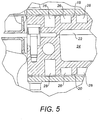
- Each mould 18, 20 is formed with a network of interconnecting channels 26, 28 as best seen in Figure 5 .
- these channels 26, 28 are connectable to an external source of fluid (not shown) which can be selectively heated or cooled and circulated through the channels 26, 28 to heat or cool the moulds 18, 20 by conduction.
- each mould 18, 20 is formed with one inlet and one outlet (not shown) with a continuous closed circuit therebetween through which fluid, typically oil, can be circulated.
- fluid typically oil
- each mould 18, 20 is formed with one inlet and one outlet (not shown) with a continuous closed circuit therebetween through which fluid, typically oil, can be circulated.
- the external source of fluid monitors and regulates the fluid temperature as required and provides a pump to circulate the fluid.
- Such devices for supplying heated or cooled oil are well-known and therefore will not be described in further detail here.
- Each mould 18, 20 is seated within an insulating jacket 30, 32.
- the moulds 18, 20 are formed of thermally conducted material such as aluminium or steel.
- the insulating jackets 30, 32 are typically a casing of steel enclosing an insulating material.
- the insulating jackets 30, 32 are provided with a reinforcement structure of ribs 34 and interconnecting beams 36 to prevent buckling of the mould halves 12, 14 in use.
- the ribs 34 also act as supporting legs for the mould halves 12, 14 and provide locations for attachment of the hinges 16 and a clamping means 38 which is discussed below.
- Clamping means 38 is provided on the upper and lower mould halves 12, 14, on the opposite side to the location of the hinges 16, for securing the mould halves 12, 14 together when in a closed position.
- the clamping means 38 comprises a pair of bolts 40 and a corresponding pair of collars 42.
- Each bolt 40 is connected at one end to a projection 44 of the reinforcing ribs 34 on the lower mould half 14, by a pivot 44.
- Each collar 42 is secured to a projection 48 of the reinforcing rib 34 on the upper mould half 12 and has an axially extending slot 50.
- bolts 40 In the closed position, bolts 40 initially hang downwards as seen in Figures 2 and 4 but can pivot clockwise and can pass through the slots 50 into the collars 42 and can then be tightened, thereby clamping the upper and lower mould halves 12, 14 together.
- the upper and lower mould halves are in the open position shown in Figure 1 .
- the moulds 18, 20 are heated by circulation of heated oil through the channels 26, 28 to a temperature higher than the melting point of the plastic material which is to be used to form the skin of the product.
- a temperature higher than the melting point of the plastic material which is to be used to form the skin of the product For example, for a plastic skin of polyethylene (PE) which has a melting point of about 190°C, the moulds 18, 20 are heated up to 220°C.
- PE polyethylene
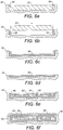
- a former 52 for example made of wood, is placed into the lower mould cavity 24 as shown in Figure 6a .
- the former 52 is slightly smaller than the mould cavity 24 and is positioned approximately centrally, thus leaving a gap 54 between the former 52 and the side walls of the cavity 24.
- Plastic material in powdered or granulated form is poured into this gap. The plastic material melts upon contact with the heated mould 24 and forms a plastic wall 56 around the sides of the mould cavity 24.
- the mould cavity 24 is deeper than the example mentioned above, e.g. 50mm or more, it may be desirable to attach the entire machine 10 to a rotational arm. This allows the moulds 18, 20 to be inverted so that any excess plastic material can fall out.
- Such rotational arms are known for other types of plastic moulding processes and therefore will not be described further. If the rotational arm is used, after removal of any excess plastic material, the moulds 18, 20 are rotated back to the starting position before continuing the process and removing the former 52.
- the former 52 is preferably formed of a material with a low thermal conductivity, such as wood, so that the plastic material tends not to adhere to it, allowing the former 52 to be easily removed. More powdered or granulated plastic material is poured into the open mould cavity 24 to cover the base of the cavity. Once again this melts upon contact with the heated mould 20 and joins with the plastic sidewall 56 to form a continuous plastic skin 58 lining the mould cavity 24 as shown in Figure 6c .
- a foamable filler material 62 is then placed into the cavity of the plastic skin 58 which has been formed in the lower mould cavity 24.
- This may be any type of heat-activated foamable product such as PE foam, but is preferably processed waste material mixed with a foaming agent. Virtually any kind of waste which would otherwise be destined for landfill can be used, including plastic, wood and metal.
- the filler material 62 may be layered up with one or more layers of other materials 64 to give special properties to the finished product, as shown in Figure 6e .
- layers of Kevlar (RTM) can be added for impact strength or carbon fibre for enhanced stiffness.
- piping for receiving electrics or fluid, into the plastic skin 58, so that it becomes incorporated into the finished article, surrounded by the other filler material 62.
- mould-in inserts such as threads, or location pins could be placed in the moulds, or alternatively drilled through afterwards.
- Post-mould inserts are also available, where the insert thread melts into the plastic skin as it is drilled in due to friction.
- the upper mould 18 is rotated about the hinges 16 into the closed position on top of the lower mould 20 and the clamping means 38 is operated to secure the mould halves together.
- the plastic skin 60 formed in the upper mould cavity 22 seamlessly bonds to the plastic skin 58 formed in the lower mould cavity 24 to provide a continuous plastic shell 66 which completely encases the filler material 62,64 within it.
- the foaming agent in the filler material is activated by the residual heat of the moulds 18, 20 and expands to completely fill the plastic shell. Because the mould cavity is not vented, the pressure and forces created by the expanding filler material are very high, hence the need for the reinforcing structure 34, 36 to spread the loads and prevent buckling of the mould halves 12, 14.
- the mould halves 12, 14 must also be of very robust construction to withstand the thermal forces created by the large temperature range they are exposed to, for example from an ambient temperature of 20°C up to 300°C.
- the reinforcing structure 34, 36 also helps to resist any distortion or deformation of the mould halves 12, 14 caused by the thermal forces.
- the machine is provided with a special closing mechanism (not shown) which allows the machine to open without damage, should overpressure arise during the expansion of the filler material.
- the circulation of heated oil through the channels 26, 28 is stopped and instead cooled oil is circulated instead to start the process of cooling the moulds 18, 20.
- the foamable filler material will start to go off once the temperature drops below certain threshold, typically about 170°C and further expansion stops.
- the moulds 18, 20 are cooled further, typically to 80°C at which point the mould halves 18, 20 can be opened and the finished plastic article removed.
- the moulded article requires no further finishing.
- the smooth walls of the mould cavities 22, 24, and the even heating of the moulds 18, 20 by virtue of the conduction of heat from the oil circulating in the channels 26, 28, provide a smooth and even surface finish to the article.
- the tight clamping of the mould halves 12, 14 together, and lack of any vents in the mould cavity, ensure a seamless join between the upper and lower plastic skins with no flash to be removed later.
- the process can be carried out manually, particularly for moulds of the size mentioned above, but is equally suitable for mechanisation with the various operations being carried out by the use of hydraulic systems, cranes or robots etc.
- the machine and manufacturing process are very energy efficient since the moulds 18, 20 are heated by direct conduction from the heated oil circulating through the channels 26, 28 and the insulating jackets 30, 32 inhibit heat loss.
- Devices for the circulation of oil and heating and cooling are readily available at comparatively low capital cost. All that is required to produce finished articles is the machine itself and one item of peripheral equipment in the form of the fluid supply and heating device. Both are comparatively low-cost items as compared with the known processes requiring ovens for heating of the moulds, conveyors and handling equipment for movement of the moulds etc. Both items are also comparatively mobile.
- the machine and the process lend themselves to inexpensive small-scale production, for example for smaller companies or for use in the third world where resources both in terms of finance and power supply may be limited. Nevertheless, since each machine is in effect in an entire manufacturing module, the machine and process are equally suitable for scaling up to large manufacturing units. In addition to low energy requirements, the process has the added environmental benefit of producing useful articles from waste material that would otherwise be destined for landfill.
Landscapes
- Engineering & Computer Science (AREA)
- Mechanical Engineering (AREA)
- Casting Or Compression Moulding Of Plastics Or The Like (AREA)
- Moulds For Moulding Plastics Or The Like (AREA)
Claims (9)
- Verfahren zum Formen eines Kunststoffartikels unter Verwendung einer Maschine (10), die ein Paar Formen (18, 20) umfasst, von welchen jede in einem Isoliermantel positioniert ist und einen Formhohlraum (22, 24) definiert, wobei die Formen (18, 20) zwischen einer geöffneten Position, in welcher die Formhohlräume (22, 24) geöffnet sind, und einer geschlossenen Position, in welcher die Formen (18, 20) zusammenwirken, um einen vollkommen geschlossenen Formhohlraum zu definieren, der nicht entlüftet ist, bewegbar sind, wobei die Formen (18, 20) miteinander über wenigstens ein Gelenk (16) verbunden sind, um welches die Formen (18, 20) schwenkbar sind, um sich zwischen der geöffneten und der geschlossenen Position zu bewegen, und Mittel (26, 28) zum Erwärmen und Abkühlen der Formen (18, 20); das Verfahren umfassend die folgenden Schritte:a) Platzieren der Formen (18, 20) in der geöffneten Position;b) Erwärmen der Formen (18, 20) durch Leiten auf eine Temperatur über dem Schmelzpunkt eines gegebenen Kunststoffmaterials, wenn die Formen (18, 20) in der geöffneten Position sind;c) Platzieren des Kunststoffmaterials in Partikelform in den Formen (18, 20), woraufhin der Kunststoff eine Haut (56, 58, 60) bildet, die jede Form (18, 20) auskleidet;d) Platzieren von ausdehnbarem Füllmaterial (62) in der Kunststoffhaut (56, 58), die in einer Form (20) gebildet ist;e) anschließendes Schließen der Formen (18, 20) und Zuklemmen dieser zur Bildung eines vollständig geschlossenen Formhohlraums, der nicht entlüftet ist, woraufhin die Kunststoffhäute (56, 58, 60) in den Formen (18, 20) aneinander haften, um eine kontinuierliche Kunststoffhülle zu bilden, die das Füllmaterial (62) vollständig ummantelt; undf) Abkühlen der Formen (18, 20) und Öffnen der Formen (18, 20) zur Entnahme der geformten Artikel;und wobei das Verfahren ferner ein Bereitstellen einer Verstärkungsstruktur (34, 36) auf den Isoliermänteln umfasst, um einem Verbiegen der Formen (18, 20) standzuhalten und um als Abstützung für die Formen (18, 20) zu dienen, wobei die Verstärkungsstruktur Rippen und verbindende Träger umfasst, und die Rippen als Stützschenkel für die Formen dienen und Stellen zur Befestigung der Gelenke und Klemmmittel bereitstellen.
- Verfahren nach Anspruch 1, wobei der Schritt des Bildens einer Kunststoffhaut in einer der Formen ein Platzieren eines Formers (52) im Formhohlraum (24), so dass ein Spalt zwischen dem Former (52) und den Seitenwänden des Hohlraums (24) belassen wird, ein Platzieren von Kunststoffmaterial in dem Spalt zur Bildung einer Kunststoffhaut (56), die die Seitenwände des Hohlraums (24) auskleidet, ein Entfernen des Formers (52) und Platzieren von weiterem Kunststoffmaterial auf dem Boden des Formhohlraums (24) zur Bildung einer Kunststoffhaut (58), die den Boden der Form auskleidet und integral mit der Kunststoffhaut (56) ist, die die Seitenwände auskleidet, umfasst.
- Verfahren nach Anspruch 2, wobei, vor der Entnahme des Formers (52), das Verfahren ferner den Schritt des Umdrehens der Form (20) zur Entfernung von jeglichem überschüssigem Kunststoffmaterial umfasst.
- Verfahren nach einem der vorhergehenden Ansprüche, wobei der Schritt des Erwärmens ein Pumpen von erwärmtem Fluid durch Kanäle (26, 28), die in den Formen (18, 20) gebildet sind, umfasst.
- Verfahren nach einem der vorhergehenden Ansprüche, wobei der Schritt des Kühlens ein Pumpen von Kühlfluid durch Kanäle (26, 28), die in den Formen (18, 20) gebildet sind, umfasst.
- Verfahren nach einem der vorhergehenden Ansprüche, wobei der Schritt des Erwärmens ein Anheben der Temperatur der Formen (18, 20) auf 220°C umfasst.
- Verfahren nach einem der vorhergehenden Ansprüche, wobei der Schritt des Kühlens ein Absenken der Temperatur der Formen (18, 20) auf 80°C umfasst.
- Verfahren nach einem der vorhergehenden Ansprüche, das ferner ein Bereitstellen eines Isoliermantels (30, 32) um jede Form (18, 20) umfasst.
- Verfahren nach einem der vorhergehenden Ansprüche, wobei der Klemmschritt ein Bereitstellen von wenigstens einem Bolzen (40) umfasst, der mit einer Form (20) schwenkbar verbunden ist und in einem runden Vorsprung (42), der an der anderen Form (18) befestigt ist, platzierbar ist.
Priority Applications (1)
| Application Number | Priority Date | Filing Date | Title |
|---|---|---|---|
| PL09772764T PL2285544T3 (pl) | 2008-06-09 | 2009-06-09 | Sposób formowania wyrobów z tworzywa sztucznego |
Applications Claiming Priority (2)
| Application Number | Priority Date | Filing Date | Title |
|---|---|---|---|
| GB0810555A GB2460838C (en) | 2008-06-09 | 2008-06-09 | Process for moulding plastic articles |
| PCT/GB2009/001424 WO2010001083A1 (en) | 2008-06-09 | 2009-06-09 | Process for moulding plastic articles |
Publications (2)
| Publication Number | Publication Date |
|---|---|
| EP2285544A1 EP2285544A1 (de) | 2011-02-23 |
| EP2285544B1 true EP2285544B1 (de) | 2019-11-06 |
Family
ID=39650716
Family Applications (1)
| Application Number | Title | Priority Date | Filing Date |
|---|---|---|---|
| EP09772764.8A Active EP2285544B1 (de) | 2008-06-09 | 2009-06-09 | Verfahren zum formen von kunststoffartikeln |
Country Status (8)
| Country | Link |
|---|---|
| US (1) | US8663515B2 (de) |
| EP (1) | EP2285544B1 (de) |
| JP (1) | JP5457439B2 (de) |
| DK (1) | DK2285544T3 (de) |
| ES (1) | ES2766949T3 (de) |
| GB (1) | GB2460838C (de) |
| PL (1) | PL2285544T3 (de) |
| WO (1) | WO2010001083A1 (de) |
Families Citing this family (18)
| Publication number | Priority date | Publication date | Assignee | Title |
|---|---|---|---|---|
| USD651623S1 (en) * | 2009-07-21 | 2012-01-03 | Upcycle Holdings Limited | Plastic moulding machine |
| GB2478796B (en) * | 2010-03-19 | 2014-01-08 | Upcycle Holdings Ltd | Process for forming a mould |
| GB2482010B (en) | 2010-07-14 | 2012-06-27 | Upcycle Holdings Ltd | Applicator device for plastic moulding machine |
| CN102363348B (zh) * | 2011-05-22 | 2013-09-18 | 浙江省天台祥和实业有限公司 | 可快速开合模的成型模具 |
| US9221104B2 (en) | 2011-08-08 | 2015-12-29 | Columbia Insurance Company | Carpet waste composite product and method for making same |
| GB201115724D0 (en) * | 2011-09-12 | 2011-10-26 | Origin Ltd | Methods of manufacturing plastic articles |
| KR101294194B1 (ko) | 2011-12-14 | 2013-08-16 | 기아자동차주식회사 | 선바이저 제조 장치 및 방법 |
| GB2498717B (en) | 2012-01-23 | 2014-06-25 | Protomax Plastics Ltd | Large format polystyrene panel |
| BR112015022947A2 (pt) | 2013-03-15 | 2017-07-18 | Miller Herman Inc | componente de espuma de partículas possuindo uma superfície texturizada |
| CN104162959A (zh) * | 2013-05-17 | 2014-11-26 | 海尔集团公司 | 一体成型具有保温内芯的保温部件的反应注射成型模具 |
| EP2826611A1 (de) * | 2013-07-18 | 2015-01-21 | HILTI Aktiengesellschaft | Verfahren zur Herstellung von Schaumformteilen in einer Verpackungshülle und Verkaufseinheit |
| GB201400232D0 (en) | 2014-01-07 | 2014-02-26 | Environmental Technology Evolution Ltd | Ete 1 |
| US20190240881A1 (en) * | 2016-10-18 | 2019-08-08 | Basf Se | Integrated articles with substantially seamless, preferably substantially faultless shells and preparation thereof |
| DE102019127756A1 (de) * | 2019-10-15 | 2021-04-15 | Kaneka Belgium Nv | Verfahren zum Herstellen eines geschäumten Kunststoffformkörpers mit einem Filmschichtüberzug |
| DE102021212180A1 (de) * | 2020-11-25 | 2022-05-25 | BSH Hausgeräte GmbH | Fertigungsanlage zum Fertigen einer Tür eines Haushaltskältegeräts, sowie Verfahren |
| GB2607352B (en) * | 2021-06-04 | 2024-04-03 | Avena Environmental Ltd | Process for manufacturing a solid product |
| CH719093A1 (de) | 2021-10-27 | 2023-05-15 | Boxs Ag | Verfahren und Vorrichtung zur Herstellung einer geschäumten Polymercompositplatte aus Misch-Kunststoffabfall. |
| EP4420854A1 (de) * | 2023-02-21 | 2024-08-28 | JSP International SARL | Form, insbesondere dampf-kolben-form, zur verarbeitung von expandierbaren oder expandierten polymerperlen zur formung einer partikelschaumkomponente |
Citations (1)
| Publication number | Priority date | Publication date | Assignee | Title |
|---|---|---|---|---|
| WO2005090041A2 (en) * | 2004-03-19 | 2005-09-29 | 3Dm Worldwide Plc | Moulding plastics articles |
Family Cites Families (20)
| Publication number | Priority date | Publication date | Assignee | Title |
|---|---|---|---|---|
| GB733623A (en) * | 1952-04-04 | 1955-07-13 | Rubber Improvement Ltd | Improvements in or relating to edge-moulding |
| DE1271379B (de) | 1960-10-13 | 1968-06-27 | Telefunken Patent | Verfahren zum Herstellen von Hohlkoerpern aus thermoplastischem Kunststoff durch Wirbelsintern |
| US3222725A (en) * | 1961-10-25 | 1965-12-14 | Neirad Ind Inc | Molding process and apparatus |
| US3419648A (en) | 1965-08-18 | 1968-12-31 | Dow Chemical Co | Method of molding polystyrene |
| US3754852A (en) * | 1965-08-24 | 1973-08-28 | Dodds T Inc | Apparatus for rotational casting |
| GB1104659A (en) * | 1965-09-13 | 1968-02-28 | Ici Ltd | Manufacture of cellular reinforced articles |
| GB1217914A (en) * | 1968-07-16 | 1971-01-06 | Blazon Inc | Apparatus for molding hollow articles from a synthetic resin |
| US3680629A (en) * | 1969-12-12 | 1972-08-01 | Mccord Corp | Apparatus for molding and curing foamed articles |
| US3989787A (en) * | 1975-07-28 | 1976-11-02 | Phillips Petroleum Company | Method of rotational molding a thermosetting article with a thermoplastic insert |
| JPS6246611A (ja) * | 1985-08-26 | 1987-02-28 | Toyo Tire & Rubber Co Ltd | 内部に芯体を有する中空表皮体の製造方法 |
| EP0679488B1 (de) | 1994-04-28 | 1998-08-05 | Kork AG Boswil | Verfahren zur Herstellung eines Formkörpers aus mindestens zwei Kunststoffschaumstoffen unterschiedlicher Dichte und Formwerkzeug zur Durchführung |
| US5454703A (en) * | 1994-06-30 | 1995-10-03 | Saturn Corporation | Apparatus for molding expanded polymer beads |
| DE19809250C2 (de) | 1998-03-05 | 2000-11-23 | Plasttechnik Engineering Greiz | Liegende Blockform zur Herstellung langer, quaderförmiger Blöcke aus schäumbarem Polystyrol |
| JP2001009857A (ja) * | 1999-07-01 | 2001-01-16 | Shiina Kasei:Kk | プラスチック発泡複合体の製造方法 |
| CN1974169B (zh) * | 2001-02-05 | 2012-02-29 | 3Dm全球有限公司 | 塑料复合制品 |
| DE10158152A1 (de) | 2001-11-28 | 2003-06-12 | Fagerdala Deutschland Gmbh | Verfahren zur Herstellung von Kunststoffhohlkörpern mit Schaumstofffüllung |
| AU2003279073A1 (en) * | 2002-09-30 | 2004-04-23 | 3Dm Technologies, Inc. | Production apparatus for forming plastic molded articles |
| EP1459862A1 (de) | 2003-03-18 | 2004-09-22 | Askle | Verfahren zur Herstellung von Formteilen und so hergestellte Integralhautgegenstände |
| DE102004006441A1 (de) * | 2004-02-09 | 2005-12-29 | Wacker & Ziegler Gmbh | Formteilwerkzeug und Verfahren zu seiner Herstellung |
| GB2425505A (en) | 2005-04-26 | 2006-11-01 | 3Dm Europ Ltd | Moulded transit or location article |
-
2008
- 2008-06-09 GB GB0810555A patent/GB2460838C/en active Active
-
2009
- 2009-06-09 US US12/995,657 patent/US8663515B2/en active Active
- 2009-06-09 EP EP09772764.8A patent/EP2285544B1/de active Active
- 2009-06-09 DK DK09772764.8T patent/DK2285544T3/da active
- 2009-06-09 WO PCT/GB2009/001424 patent/WO2010001083A1/en not_active Ceased
- 2009-06-09 PL PL09772764T patent/PL2285544T3/pl unknown
- 2009-06-09 ES ES09772764T patent/ES2766949T3/es active Active
- 2009-06-09 JP JP2011513044A patent/JP5457439B2/ja active Active
Patent Citations (1)
| Publication number | Priority date | Publication date | Assignee | Title |
|---|---|---|---|---|
| WO2005090041A2 (en) * | 2004-03-19 | 2005-09-29 | 3Dm Worldwide Plc | Moulding plastics articles |
Also Published As
| Publication number | Publication date |
|---|---|
| DK2285544T3 (da) | 2020-02-03 |
| JP5457439B2 (ja) | 2014-04-02 |
| GB2460838A (en) | 2009-12-16 |
| GB2460838C (en) | 2013-11-06 |
| GB2460838A8 (en) | 2010-03-10 |
| EP2285544A1 (de) | 2011-02-23 |
| GB2460838B (en) | 2010-04-28 |
| US8663515B2 (en) | 2014-03-04 |
| WO2010001083A1 (en) | 2010-01-07 |
| ES2766949T3 (es) | 2020-06-15 |
| US20110081516A1 (en) | 2011-04-07 |
| GB0810555D0 (en) | 2008-07-16 |
| JP2011522724A (ja) | 2011-08-04 |
| HK1135352A1 (zh) | 2010-06-04 |
| PL2285544T3 (pl) | 2020-06-01 |
Similar Documents
| Publication | Publication Date | Title |
|---|---|---|
| US8663515B2 (en) | Process for moulding plastic articles | |
| US20010020757A1 (en) | Apparatus and process for producing molded plastic articles | |
| GB2494484A (en) | Method of manufacturing a composite sandwich plastics article. | |
| BR112015001318B1 (pt) | processo para conformar materiais espumados | |
| US20070275229A1 (en) | Molded article with foam-encased adhesion-resistant reinforcing member and method | |
| KR101358336B1 (ko) | Eps/epp 포장재의 그레이징 성형 장치 및 방법 | |
| US20040045488A1 (en) | Molded table and its method of manufacture | |
| KR101506453B1 (ko) | 발포 금속제품 제조방법 및 이를 이용한 발포 금속제품 | |
| CN207156311U (zh) | 冰箱箱体发泡模具 | |
| KR101134489B1 (ko) | 발포성형체 제조장치 및 제조방법 | |
| US20050129901A1 (en) | Molded article with adhesion-resistant reinforcing member and method | |
| WO2014114955A1 (en) | Method and apparatus for production of carbon fibre components | |
| TW202138169A (zh) | 用於生產由複合材料構成之四角形殼件的方法及工具 | |
| US20050129921A1 (en) | Molded article with foam-encased reinforcing member | |
| US20110248418A1 (en) | Moulding Method and A Moulding Machine | |
| WO2005090041A2 (en) | Moulding plastics articles | |
| JP5377251B2 (ja) | 発泡樹脂容器 | |
| KR101200361B1 (ko) | 발포 성형 금형장치 | |
| JP2010023499A (ja) | 成形金型およびそれを用いた成形方法 | |
| JP5984264B2 (ja) | 軽量簡易樹脂金型及びその製造方法 | |
| JP2024065964A (ja) | 急速加熱冷却成形用金型 | |
| JP5294212B2 (ja) | 発泡樹脂製品の製造方法および発泡樹脂製品の成形機 | |
| US20200223107A1 (en) | Systems and methods for rotational molding | |
| Afonso et al. | ISF Rapid Tooling Applications | |
| JP6553868B2 (ja) | 樹脂成形用金型装置 |
Legal Events
| Date | Code | Title | Description |
|---|---|---|---|
| PUAI | Public reference made under article 153(3) epc to a published international application that has entered the european phase |
Free format text: ORIGINAL CODE: 0009012 |
|
| 17P | Request for examination filed |
Effective date: 20101129 |
|
| AK | Designated contracting states |
Kind code of ref document: A1 Designated state(s): AT BE BG CH CY CZ DE DK EE ES FI FR GB GR HR HU IE IS IT LI LT LU LV MC MK MT NL NO PL PT RO SE SI SK TR |
|
| AX | Request for extension of the european patent |
Extension state: AL BA RS |
|
| RAP1 | Party data changed (applicant data changed or rights of an application transferred) |
Owner name: UPCYCLE HOLDINGS LIMITED |
|
| RIN1 | Information on inventor provided before grant (corrected) |
Inventor name: RODLSBERGER, ALFRED Inventor name: STILLWELL, NICHOLAS JOHN |
|
| DAX | Request for extension of the european patent (deleted) | ||
| 17Q | First examination report despatched |
Effective date: 20150507 |
|
| STAA | Information on the status of an ep patent application or granted ep patent |
Free format text: STATUS: EXAMINATION IS IN PROGRESS |
|
| GRAP | Despatch of communication of intention to grant a patent |
Free format text: ORIGINAL CODE: EPIDOSNIGR1 |
|
| STAA | Information on the status of an ep patent application or granted ep patent |
Free format text: STATUS: GRANT OF PATENT IS INTENDED |
|
| INTG | Intention to grant announced |
Effective date: 20190527 |
|
| GRAS | Grant fee paid |
Free format text: ORIGINAL CODE: EPIDOSNIGR3 |
|
| GRAA | (expected) grant |
Free format text: ORIGINAL CODE: 0009210 |
|
| STAA | Information on the status of an ep patent application or granted ep patent |
Free format text: STATUS: THE PATENT HAS BEEN GRANTED |
|
| AK | Designated contracting states |
Kind code of ref document: B1 Designated state(s): AT BE BG CH CY CZ DE DK EE ES FI FR GB GR HR HU IE IS IT LI LT LU LV MC MK MT NL NO PL PT RO SE SI SK TR |
|
| REG | Reference to a national code |
Ref country code: GB Ref legal event code: FG4D |
|
| REG | Reference to a national code |
Ref country code: CH Ref legal event code: EP Ref country code: AT Ref legal event code: REF Ref document number: 1198140 Country of ref document: AT Kind code of ref document: T Effective date: 20191115 |
|
| REG | Reference to a national code |
Ref country code: IE Ref legal event code: FG4D |
|
| REG | Reference to a national code |
Ref country code: DE Ref legal event code: R096 Ref document number: 602009060365 Country of ref document: DE |
|
| REG | Reference to a national code |
Ref country code: CH Ref legal event code: NV Representative=s name: KIRKER AND CIE S.A., CH |
|
| REG | Reference to a national code |
Ref country code: DK Ref legal event code: T3 Effective date: 20200129 |
|
| REG | Reference to a national code |
Ref country code: SE Ref legal event code: TRGR |
|
| REG | Reference to a national code |
Ref country code: NL Ref legal event code: FP |
|
| REG | Reference to a national code |
Ref country code: LT Ref legal event code: MG4D |
|
| PG25 | Lapsed in a contracting state [announced via postgrant information from national office to epo] |
Ref country code: NO Free format text: LAPSE BECAUSE OF FAILURE TO SUBMIT A TRANSLATION OF THE DESCRIPTION OR TO PAY THE FEE WITHIN THE PRESCRIBED TIME-LIMIT Effective date: 20200206 Ref country code: LT Free format text: LAPSE BECAUSE OF FAILURE TO SUBMIT A TRANSLATION OF THE DESCRIPTION OR TO PAY THE FEE WITHIN THE PRESCRIBED TIME-LIMIT Effective date: 20191106 Ref country code: LV Free format text: LAPSE BECAUSE OF FAILURE TO SUBMIT A TRANSLATION OF THE DESCRIPTION OR TO PAY THE FEE WITHIN THE PRESCRIBED TIME-LIMIT Effective date: 20191106 Ref country code: PT Free format text: LAPSE BECAUSE OF FAILURE TO SUBMIT A TRANSLATION OF THE DESCRIPTION OR TO PAY THE FEE WITHIN THE PRESCRIBED TIME-LIMIT Effective date: 20200306 Ref country code: FI Free format text: LAPSE BECAUSE OF FAILURE TO SUBMIT A TRANSLATION OF THE DESCRIPTION OR TO PAY THE FEE WITHIN THE PRESCRIBED TIME-LIMIT Effective date: 20191106 Ref country code: BG Free format text: LAPSE BECAUSE OF FAILURE TO SUBMIT A TRANSLATION OF THE DESCRIPTION OR TO PAY THE FEE WITHIN THE PRESCRIBED TIME-LIMIT Effective date: 20200206 |
|
| REG | Reference to a national code |
Ref country code: GR Ref legal event code: EP Ref document number: 20200400305 Country of ref document: GR Effective date: 20200511 |
|
| PG25 | Lapsed in a contracting state [announced via postgrant information from national office to epo] |
Ref country code: IS Free format text: LAPSE BECAUSE OF FAILURE TO SUBMIT A TRANSLATION OF THE DESCRIPTION OR TO PAY THE FEE WITHIN THE PRESCRIBED TIME-LIMIT Effective date: 20200306 Ref country code: HR Free format text: LAPSE BECAUSE OF FAILURE TO SUBMIT A TRANSLATION OF THE DESCRIPTION OR TO PAY THE FEE WITHIN THE PRESCRIBED TIME-LIMIT Effective date: 20191106 |
|
| REG | Reference to a national code |
Ref country code: ES Ref legal event code: FG2A Ref document number: 2766949 Country of ref document: ES Kind code of ref document: T3 Effective date: 20200615 |
|
| PG25 | Lapsed in a contracting state [announced via postgrant information from national office to epo] |
Ref country code: EE Free format text: LAPSE BECAUSE OF FAILURE TO SUBMIT A TRANSLATION OF THE DESCRIPTION OR TO PAY THE FEE WITHIN THE PRESCRIBED TIME-LIMIT Effective date: 20191106 Ref country code: RO Free format text: LAPSE BECAUSE OF FAILURE TO SUBMIT A TRANSLATION OF THE DESCRIPTION OR TO PAY THE FEE WITHIN THE PRESCRIBED TIME-LIMIT Effective date: 20191106 |
|
| REG | Reference to a national code |
Ref country code: DE Ref legal event code: R097 Ref document number: 602009060365 Country of ref document: DE |
|
| PG25 | Lapsed in a contracting state [announced via postgrant information from national office to epo] |
Ref country code: SK Free format text: LAPSE BECAUSE OF FAILURE TO SUBMIT A TRANSLATION OF THE DESCRIPTION OR TO PAY THE FEE WITHIN THE PRESCRIBED TIME-LIMIT Effective date: 20191106 |
|
| PLBE | No opposition filed within time limit |
Free format text: ORIGINAL CODE: 0009261 |
|
| STAA | Information on the status of an ep patent application or granted ep patent |
Free format text: STATUS: NO OPPOSITION FILED WITHIN TIME LIMIT |
|
| 26N | No opposition filed |
Effective date: 20200807 |
|
| REG | Reference to a national code |
Ref country code: AT Ref legal event code: UEP Ref document number: 1198140 Country of ref document: AT Kind code of ref document: T Effective date: 20191106 |
|
| PG25 | Lapsed in a contracting state [announced via postgrant information from national office to epo] |
Ref country code: SI Free format text: LAPSE BECAUSE OF FAILURE TO SUBMIT A TRANSLATION OF THE DESCRIPTION OR TO PAY THE FEE WITHIN THE PRESCRIBED TIME-LIMIT Effective date: 20191106 |
|
| PG25 | Lapsed in a contracting state [announced via postgrant information from national office to epo] |
Ref country code: MC Free format text: LAPSE BECAUSE OF FAILURE TO SUBMIT A TRANSLATION OF THE DESCRIPTION OR TO PAY THE FEE WITHIN THE PRESCRIBED TIME-LIMIT Effective date: 20191106 |
|
| PG25 | Lapsed in a contracting state [announced via postgrant information from national office to epo] |
Ref country code: LU Free format text: LAPSE BECAUSE OF NON-PAYMENT OF DUE FEES Effective date: 20200609 |
|
| PG25 | Lapsed in a contracting state [announced via postgrant information from national office to epo] |
Ref country code: MT Free format text: LAPSE BECAUSE OF FAILURE TO SUBMIT A TRANSLATION OF THE DESCRIPTION OR TO PAY THE FEE WITHIN THE PRESCRIBED TIME-LIMIT Effective date: 20191106 Ref country code: CY Free format text: LAPSE BECAUSE OF FAILURE TO SUBMIT A TRANSLATION OF THE DESCRIPTION OR TO PAY THE FEE WITHIN THE PRESCRIBED TIME-LIMIT Effective date: 20191106 |
|
| PG25 | Lapsed in a contracting state [announced via postgrant information from national office to epo] |
Ref country code: MK Free format text: LAPSE BECAUSE OF FAILURE TO SUBMIT A TRANSLATION OF THE DESCRIPTION OR TO PAY THE FEE WITHIN THE PRESCRIBED TIME-LIMIT Effective date: 20191106 |
|
| PGFP | Annual fee paid to national office [announced via postgrant information from national office to epo] |
Ref country code: DE Payment date: 20250618 Year of fee payment: 17 Ref country code: PL Payment date: 20250513 Year of fee payment: 17 |
|
| PGFP | Annual fee paid to national office [announced via postgrant information from national office to epo] |
Ref country code: GB Payment date: 20250617 Year of fee payment: 17 Ref country code: DK Payment date: 20250618 Year of fee payment: 17 |
|
| PGFP | Annual fee paid to national office [announced via postgrant information from national office to epo] |
Ref country code: NL Payment date: 20250616 Year of fee payment: 17 Ref country code: BE Payment date: 20250616 Year of fee payment: 17 |
|
| PGFP | Annual fee paid to national office [announced via postgrant information from national office to epo] |
Ref country code: FR Payment date: 20250617 Year of fee payment: 17 |
|
| PGFP | Annual fee paid to national office [announced via postgrant information from national office to epo] |
Ref country code: GR Payment date: 20250619 Year of fee payment: 17 |
|
| PGFP | Annual fee paid to national office [announced via postgrant information from national office to epo] |
Ref country code: AT Payment date: 20250618 Year of fee payment: 17 |
|
| PGFP | Annual fee paid to national office [announced via postgrant information from national office to epo] |
Ref country code: TR Payment date: 20250523 Year of fee payment: 17 |
|
| PGFP | Annual fee paid to national office [announced via postgrant information from national office to epo] |
Ref country code: CZ Payment date: 20250513 Year of fee payment: 17 |
|
| PGFP | Annual fee paid to national office [announced via postgrant information from national office to epo] |
Ref country code: IE Payment date: 20250617 Year of fee payment: 17 |
|
| PGFP | Annual fee paid to national office [announced via postgrant information from national office to epo] |
Ref country code: SE Payment date: 20250618 Year of fee payment: 17 |
|
| PGFP | Annual fee paid to national office [announced via postgrant information from national office to epo] |
Ref country code: ES Payment date: 20250710 Year of fee payment: 17 |
|
| PGFP | Annual fee paid to national office [announced via postgrant information from national office to epo] |
Ref country code: IT Payment date: 20250618 Year of fee payment: 17 |
|
| PGFP | Annual fee paid to national office [announced via postgrant information from national office to epo] |
Ref country code: CH Payment date: 20250701 Year of fee payment: 17 |