EP2285522B1 - Laser machining tool having expanded work space - Google Patents
Laser machining tool having expanded work space Download PDFInfo
- Publication number
- EP2285522B1 EP2285522B1 EP09741860.2A EP09741860A EP2285522B1 EP 2285522 B1 EP2285522 B1 EP 2285522B1 EP 09741860 A EP09741860 A EP 09741860A EP 2285522 B1 EP2285522 B1 EP 2285522B1
- Authority
- EP
- European Patent Office
- Prior art keywords
- laser processing
- processing machine
- heads
- laser
- machine according
- Prior art date
- Legal status (The legal status is an assumption and is not a legal conclusion. Google has not performed a legal analysis and makes no representation as to the accuracy of the status listed.)
- Active
Links
- 238000003754 machining Methods 0.000 title description 17
- 238000005192 partition Methods 0.000 claims description 9
- 230000014759 maintenance of location Effects 0.000 claims 2
- 230000008878 coupling Effects 0.000 description 4
- 238000010168 coupling process Methods 0.000 description 4
- 238000005859 coupling reaction Methods 0.000 description 4
- 238000003466 welding Methods 0.000 description 3
- 239000012876 carrier material Substances 0.000 description 2
- 238000000034 method Methods 0.000 description 2
- 230000000295 complement effect Effects 0.000 description 1
- 238000001816 cooling Methods 0.000 description 1
- 230000000694 effects Effects 0.000 description 1
- 238000005304 joining Methods 0.000 description 1
- 238000004519 manufacturing process Methods 0.000 description 1
- 239000000463 material Substances 0.000 description 1
- 239000002184 metal Substances 0.000 description 1
- 230000001681 protective effect Effects 0.000 description 1
Images


Classifications
-
- B—PERFORMING OPERATIONS; TRANSPORTING
- B23—MACHINE TOOLS; METAL-WORKING NOT OTHERWISE PROVIDED FOR
- B23K—SOLDERING OR UNSOLDERING; WELDING; CLADDING OR PLATING BY SOLDERING OR WELDING; CUTTING BY APPLYING HEAT LOCALLY, e.g. FLAME CUTTING; WORKING BY LASER BEAM
- B23K26/00—Working by laser beam, e.g. welding, cutting or boring
- B23K26/02—Positioning or observing the workpiece, e.g. with respect to the point of impact; Aligning, aiming or focusing the laser beam
- B23K26/06—Shaping the laser beam, e.g. by masks or multi-focusing
- B23K26/067—Dividing the beam into multiple beams, e.g. multifocusing
-
- B—PERFORMING OPERATIONS; TRANSPORTING
- B23—MACHINE TOOLS; METAL-WORKING NOT OTHERWISE PROVIDED FOR
- B23K—SOLDERING OR UNSOLDERING; WELDING; CLADDING OR PLATING BY SOLDERING OR WELDING; CUTTING BY APPLYING HEAT LOCALLY, e.g. FLAME CUTTING; WORKING BY LASER BEAM
- B23K26/00—Working by laser beam, e.g. welding, cutting or boring
- B23K26/02—Positioning or observing the workpiece, e.g. with respect to the point of impact; Aligning, aiming or focusing the laser beam
- B23K26/06—Shaping the laser beam, e.g. by masks or multi-focusing
- B23K26/0604—Shaping the laser beam, e.g. by masks or multi-focusing by a combination of beams
-
- B—PERFORMING OPERATIONS; TRANSPORTING
- B23—MACHINE TOOLS; METAL-WORKING NOT OTHERWISE PROVIDED FOR
- B23K—SOLDERING OR UNSOLDERING; WELDING; CLADDING OR PLATING BY SOLDERING OR WELDING; CUTTING BY APPLYING HEAT LOCALLY, e.g. FLAME CUTTING; WORKING BY LASER BEAM
- B23K26/00—Working by laser beam, e.g. welding, cutting or boring
- B23K26/02—Positioning or observing the workpiece, e.g. with respect to the point of impact; Aligning, aiming or focusing the laser beam
- B23K26/06—Shaping the laser beam, e.g. by masks or multi-focusing
- B23K26/067—Dividing the beam into multiple beams, e.g. multifocusing
- B23K26/0673—Dividing the beam into multiple beams, e.g. multifocusing into independently operating sub-beams, e.g. beam multiplexing to provide laser beams for several stations
-
- B—PERFORMING OPERATIONS; TRANSPORTING
- B23—MACHINE TOOLS; METAL-WORKING NOT OTHERWISE PROVIDED FOR
- B23K—SOLDERING OR UNSOLDERING; WELDING; CLADDING OR PLATING BY SOLDERING OR WELDING; CUTTING BY APPLYING HEAT LOCALLY, e.g. FLAME CUTTING; WORKING BY LASER BEAM
- B23K26/00—Working by laser beam, e.g. welding, cutting or boring
- B23K26/08—Devices involving relative movement between laser beam and workpiece
- B23K26/083—Devices involving movement of the workpiece in at least one axial direction
-
- B—PERFORMING OPERATIONS; TRANSPORTING
- B23—MACHINE TOOLS; METAL-WORKING NOT OTHERWISE PROVIDED FOR
- B23K—SOLDERING OR UNSOLDERING; WELDING; CLADDING OR PLATING BY SOLDERING OR WELDING; CUTTING BY APPLYING HEAT LOCALLY, e.g. FLAME CUTTING; WORKING BY LASER BEAM
- B23K26/00—Working by laser beam, e.g. welding, cutting or boring
- B23K26/08—Devices involving relative movement between laser beam and workpiece
- B23K26/0869—Devices involving movement of the laser head in at least one axial direction
-
- B—PERFORMING OPERATIONS; TRANSPORTING
- B23—MACHINE TOOLS; METAL-WORKING NOT OTHERWISE PROVIDED FOR
- B23K—SOLDERING OR UNSOLDERING; WELDING; CLADDING OR PLATING BY SOLDERING OR WELDING; CUTTING BY APPLYING HEAT LOCALLY, e.g. FLAME CUTTING; WORKING BY LASER BEAM
- B23K26/00—Working by laser beam, e.g. welding, cutting or boring
- B23K26/08—Devices involving relative movement between laser beam and workpiece
- B23K26/10—Devices involving relative movement between laser beam and workpiece using a fixed support, i.e. involving moving the laser beam
Definitions
- the invention relates to a laser processing machine according to the preamble of claim 1 (see, for example, US Pat. JP 02/133187 A ).
- laser processing machines for example from the JP 03-138092 A known in which a workpiece to be processed, on a workpiece support is hung up. Above the workpiece support, a gantry can be moved in the longitudinal direction of the workpiece. On the portal can be arranged on one side of a laser processing head, which is movable by the movement of the portal relative to the workpiece. With the help of the laser processing head, a workpiece can be processed. With the known embodiment of a laser processing machine only workpieces are to be processed, which are substantially smaller than the base of the laser processing machine. The width of the portal creates an area that is not accessible to a tool and thus can not be processed.
- From the DE 196 20 391 A1 is an apparatus for processing flat objects, which consist of a non-metallic carrier material, such.
- a non-metallic carrier material such as paper, cardboard, plastic or the like.
- a working plane in which an object to be processed is arranged, with an arm which engages over the working plane and which is guided over the entire working plane displaced in one direction, and with a machining head known for editing the object, wherein the machining head is guided displaceably to the arm at right angles to its direction of movement.
- a plurality of processing heads may be provided on the arm.
- the processing heads can be designed to draw, cut or groove the non-metallic carrier material.
- a material processing station with a processing unit which can be positioned along three mutually perpendicular axes.
- a stand is for this purpose usually arranged vertically and provided with horizontally extending spindle drives for a carriage, which in turn is in turn equipped with spindle drives and is displaceable perpendicular to the ground.
- This carriage receives the processing unit, which in turn is displaceable perpendicular to the plane of the stator.
- the DE 203 06 581 U1 discloses a laser welding arrangement for welding components of vehicle bodies, consisting of a plurality of laser welding heads designed as remote lasers and arranged at a distance from the component.
- a method for machining workpieces by means of a plurality of laser beams wherein a plurality of laser beams are combined via a beam combiner and passed over a common beam guidance on a workpiece.
- the DE 10 2005 025 506 A1 discloses a laser processing machine configured to machine a sheet-metal workpiece mounted on a machining table by relatively moving the machining table and laser collimating and positioning means and fixing a next area to be machined on the machining table by repeatedly moving the sheet-like workpiece longitudinally the processing of an area to be processed is finished.
- the DE 10 2006 021 622 A1 discloses a device for laser joining by means of the laser-remote method, wherein a laser beam is guided by means of a beam deflection optics within a reachable by the laser beam workspace or workspace over a region to be joined and the area to be joined Shielding gas is supplied. It is provided that the protective gas is selectively supplied to a work area or work space.
- the object of the present invention is to provide a laser processing machine having a larger working space, so that larger workpieces can be processed or the space required for the laser processing machine is reduced.
- a laser processing machine with the features of claim 1.
- the work areas of the opposite laser processing heads now overlap and complement each other completely.
- the machine base area and the working area which is essentially defined by the movability of a laser processing head in the X and Y directions, can be almost brought into coincidence.
- the work area can be increased, so that larger workpieces can be edited, or the space requirements, especially the footprint of the laser processing machine can be reduced.
- the manufacturing advantage lies in the fact that, as before, a machine with laser processing heads, can only be made on one side of the support structure and the customer can decide very late whether he also wants / needs on the opposite side laser processing heads.
- the beam switch can be controlled and can be arranged to be movable, so that, as required, the laser beam can be directed to one or the other laser processing head.
- the work area can be particularly well utilized.
- the footprint of the laser processing machine is substantially identical to the working range of the laser processing heads.
- the workpiece can be processed simultaneously in several places, so that a higher clocking can be performed.
- the laser processing heads are movable along the support structure. As a result, almost all areas of the workpiece are accessible through the laser processing heads. It may be easier to move the laser processing heads along the support structure than to move the workpiece relative to the support structure, as this would require a higher mass to be moved.
- the laser processing heads can be moved independently of one another or coupled on the same side of the support structure. During the machining of the workpiece can be switched at a suitable location of the one laser processing head to the other laser processing head.
- switching from one laser processing head to another laser processing head can also be done in another axial direction, namely from a laser processing head disposed on a first side of the support structure to a laser processing head disposed on the opposite side of the support structure.
- Laser processing heads arranged on different sides of the support structure can either be coupled or moved independently of one another along the support structure.
- At least one laser processing head has an additional axis, a highly dynamic workpiece machining can be carried out locally.
- the support structure is movable relative to the workpiece support. This results in an even better utilization of the work space.
- At least one laser processing head is movable relative to the carriage, in particular linearly.
- the relative position of one laser processing head to the other laser processing head on the same carriage can be changed.
- a highly dynamic workpiece machining is possible.
- the laser processing heads are movable independently of one another or coupled relative to the carriage, in particular linearly.
- jet generators are provided.
- many beam generators can be provided as laser processing heads are provided. It can be a fixed assignment of
- Beam generator made to a laser processing head. Through skillful nesting of similar workpieces, two workpieces can be machined simultaneously by growing two beam generators. Furthermore, it is conceivable that the power of a beam generator is divided at a suitable location and is directed to two laser processing heads. For this purpose, it is advantageous if a beam splitting module is provided.
- the jets of two beam generators can be combined to form an energy beam at a suitable location.
- a beam coupler can be provided.
- the beam coupler can in turn be connected to a beam switch or even be moved, so that the beam coupler can also be used as a switch and can supply the energy beam to different laser processing heads.
- a partition may be provided so that on the one side of the partition, a workpiece machining can be performed, while on the other side of the partition, a workpiece can be loaded or unloaded. If the partition is removed, larger workpieces can be machined.
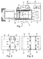
- FIG. 1 shows a laser processing machine 10 with a workpiece support 11, on which a workpiece 12 is arranged.
- a support structure 13 is arranged in the form of a portal.
- the support structure 13 is movable in the double arrow direction 14 along guides 15, 16.
- the support structure 13 is driven by linear drives.
- the arrangement effecting the movement in double arrow direction 14 is referred to as the (tool) axis.
- laser processing heads 17, 18 are arranged on both sides. These are movable in the double arrow direction 19 relative to the support structure 13. Arrangements which effect a movement in double arrow direction 19 are also referred to as (tool) axis. Because laser processing heads 17, 18 are arranged on both sides of the support structure, a maximum working range is achieved.
- a workpiece could be machined that has substantially the length of the guides 15, 16 and whose width is almost equal to the distance of the guides 15, 16.
- a control panel 20 for controlling the laser processing machine 10 around additional facilities, such as a control panel 20, a cabinet 21, a suction 22, a Cooling unit 23, a power supply 24, a hydraulic unit 25 and a plate changer 26 for loading and unloading of the workpieces.
- a total of four laser processing heads 32 to 35 wherein in each case two laser processing heads 32, 35 and 33, 34 are arranged on one side of the support structure 31.
- the laser processing heads 32 to 35 are each arranged on a carriage 36 to 39.
- the carriages 36 to 39 are movable in double arrow directions Y1 and Y2 and the entire support structure 31 in the double arrow direction X. This means that a working area or working space indicated by the surface 40 can be processed by the laser processing machine 30.
- the working area 40 corresponds almost to the base area 41 of the laser processing machine 30. Due to the width of the support structure 31, there is no area corresponding to the width of the support structure 31 in which no processing can take place.
- the laser processing heads 32 to 35 sit according to the invention on a small additional axis, so that a highly dynamic movement of the laser processing heads 32 to 35 relative to the carriage 36 to 39 is possible.
- each carriage 51 to 54 two laser processing heads 55 to 62 are provided.
- the laser processing heads 55 to 62 are, according to the invention, coupled to the carriage or arranged to be movable independently of one another.
- the working area is identified by the reference numeral 63 and the base area of the laser processing machine 50 by the reference numeral 64.
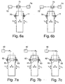
- FIGS. 4a, 4b schematically the power switching between two laser processing heads 55, 66 is shown.
- a beam generator 67 a beam is generated and transmitted via a beam splitter 68 to the laser processing head 65 (FIG. Fig. 4a ) or the laser processing head 66 (FIG. Fig. 4b ).
- the beam splitter 68 may be arranged to be movable and controlled by a controller.
- a plurality of beam generators 69, 70 are present, each of which interacts with an associated laser processing head 71, 72.
- the beams of the beam generators 73, 74 may be directed to a beam coupling module 75, where the laser power is at least partially added and subsequently transferred to one of the laser processing heads 76, 77.
- the beam coupling module 75 can be arranged to be movable so that optionally the laser power to the laser processing head 76 (FIG. Fig. 6a ) or 77 ( Fig. 6b ) can be handed over. If necessary, only a part of the coupled power can also be transferred to the laser processing heads 76, 77 by the beam coupling module 75.
- FIGS. 7a to 7c shown embodiment of the invention can be generated by means of a beam generator 80 laser power and passed through a beam splitter module 81 to a first laser processing head 82 or a second laser processing head 83.
- the beam splitter module is passive. This means that the laser power of the beam generator 80 either to the laser processing head 82 (FIG. Fig. 7a ) or the laser processing head 83 (FIG. Fig. 7b ).
- FIG. 7c is the beam splitter module active. This means that the laser power of the beam generator 80 is split and a part of the generated laser power can be transferred to both laser processing heads 82, 83.
- FIGS. 4 to 7 Different beam guidance options were shown. This was illustrated by way of example with reference to two laser processing heads lying opposite one another on a support structure. It is understood that these concepts also apply to a plurality of opposite to a support structure Laser processing heads are transferable. In addition, it is conceivable to apply the beam guidance concepts to two or more laser processing heads which are located on the same side of a support structure.
- FIG. 8 an embodiment of a laser processing machine 90 is shown having a partition 91.
- the partition wall 91 it is possible to perform workpiece machining on one side 92 and to load or unload a workpiece 94 on the other side 93. Since the support structure with the laser processing head can approach the partition wall from both sides, almost no additional space requirement arises in this processing mode.
- the support structure 95 can be transferred to the left side 93 so that workpiece machining can take place there while the workpiece 96 machined on the right side 92 can be removed and a new workpiece loaded. It is also conceivable to omit the dividing wall 91 and to machine a workpiece which extends on both sides 92, 93.
Landscapes
- Physics & Mathematics (AREA)
- Optics & Photonics (AREA)
- Engineering & Computer Science (AREA)
- Plasma & Fusion (AREA)
- Mechanical Engineering (AREA)
- Laser Beam Processing (AREA)
Abstract
Description
Die Erfindung betrifft eine Laserbearbeitungsmaschine gemäß dem Oberbegriff des Anspruchs 1 (siehe, z.B.,
Es sind Laserbearbeitungsmaschinen, beispielsweise aus der
Aus der
Aus der
Aus der
Die
Aus der
Die
Aus der
Aus der
Aus der
Die
Aus der
Aufgabe der vorliegenden Erfindung ist es, eine Laserbearbeitungsmaschine bereitzustellen, die einen größeren Arbeitsraum aufweist, so dass größere Werkstücke bearbeitet werden können oder der Platzbedarf für die Laserbearbeitungsmaschine reduziert wird.The object of the present invention is to provide a laser processing machine having a larger working space, so that larger workpieces can be processed or the space required for the laser processing machine is reduced.
Gelöst wird diese Aufgabe erfindungsgemäß durch eine Laserbearbeitungsmaschine mit den Merkmalen des Anspruchs 1. Die Arbeitsbereiche der sich gegenüberliegenden Laserbearbeitungsköpfe überlappen sich nun und ergänzen sich gegenseitig lückenlos. Dadurch können die Maschinengrundfläche und der Arbeitsbereich, der im Wesentlichen durch die Verfahrbarkeit eines Laserbearbeitungskopfs in X- und Y-Richtung definiert wird, nahezu in Überdeckung gebracht werden. Somit kann entweder der Arbeitsbereich vergrößert werden, so dass größere Werkstücke bearbeitet werden können, oder der Platzbedarf, insbesondere der Grundflächenbedarf der Laserbearbeitungsmaschine, kann reduziert werden. Der fertigungstechnische Vorteil liegt darin, dass wie bisher eine Maschine mit Laserbearbeitungsköpfen, nur auf einer Seite der Tragstruktur hergestellt werden kann und der Kunde sich sehr spät entscheiden kann, ob er auch auf der gegenüber liegenden Seite Laserbearbeitungsköpfe wünscht/benötigt.This object is achieved according to the invention by a laser processing machine with the features of
Die Strahlweiche kann angesteuert werden und kann bewegbar angeordnet sein, so dass je nach Bedarf der Laserstrahl auf den einen oder anderen Laserbearbeitungskopf gelenkt werden kann.The beam switch can be controlled and can be arranged to be movable, so that, as required, the laser beam can be directed to one or the other laser processing head.
Besondere Vorteile ergeben sich, wenn auf beiden Seiten der Tragstruktur zumindest zwei Laserbearbeitungsköpfe angeordnet sind. Durch diese Vervielfachung der Laserbearbeitungsköpfe kann der Arbeitsbereich besonders gut ausgenutzt werden. Die Grundfläche der Laserbearbeitungsmaschine ist im Wesentlichen identisch mit dem Arbeitsbereich der Laserbearbeitungsköpfe. Außerdem kann das Werkstück an mehreren Stellen gleichzeitig bearbeitet werden, so dass eine höhere Taktung durchgeführt werden kann.Particular advantages arise when at least two laser processing heads are arranged on both sides of the support structure. Through this multiplication of Laser processing heads, the work area can be particularly well utilized. The footprint of the laser processing machine is substantially identical to the working range of the laser processing heads. In addition, the workpiece can be processed simultaneously in several places, so that a higher clocking can be performed.
Gemäß der Erfindung sind die Laserbearbeitungsköpfe entlang der Tragstruktur bewegbar sind. Dadurch sind nahezu alle Bereiche des Werkstücks durch die Laserbearbeitungsköpfe zugänglich. Es ist unter Umständen einfacher, die Laserbearbeitungsköpfe entlang der Tragstruktur zu bewegen als das Werkstück relativ zu der Tragstruktur zu bewegen, da dadurch eine höhere Masse bewegt werden müsste.According to the invention, the laser processing heads are movable along the support structure. As a result, almost all areas of the workpiece are accessible through the laser processing heads. It may be easier to move the laser processing heads along the support structure than to move the workpiece relative to the support structure, as this would require a higher mass to be moved.
Gemäß einer Weiterbildung kann vorgesehen sein, dass die Laserbearbeitungsköpfe auf derselben Seite der Tragstruktur unabhängig voneinander oder gekoppelt bewegbar sind. Während der Bearbeitung des Werkstücks kann an geeigneter Stelle von dem einen Laserbearbeitungskopf auf den anderen Laserbearbeitungskopf umgeschaltet werden.According to a development it can be provided that the laser processing heads can be moved independently of one another or coupled on the same side of the support structure. During the machining of the workpiece can be switched at a suitable location of the one laser processing head to the other laser processing head.
Die Umschaltung von einem Laserbearbeitungskopf auf einen anderen Laserbearbeitungskopf kann jedoch auch in einer anderen Achsrichtung erfolgen, nämlich von einem Laserbearbeitungskopf, der auf einer ersten Seite der Tragstruktur angeordnet ist, auf einen Laserbearbeitungskopf, der auf der gegenüberliegenden Seite der Tragstruktur angeordnet ist. Auf unterschiedlichen Seiten der Tragstruktur angeordnete Laserbearbeitungsköpfe können entweder gekoppelt oder unabhängig voneinander entlang der Tragstruktur verfahren werden.However, switching from one laser processing head to another laser processing head can also be done in another axial direction, namely from a laser processing head disposed on a first side of the support structure to a laser processing head disposed on the opposite side of the support structure. Laser processing heads arranged on different sides of the support structure can either be coupled or moved independently of one another along the support structure.
Da gemäß der Erfindung zumindest ein Laserbearbeitungskopf eine zusätzliche Achse aufweist, kann lokal begrenzt eine hochdynamische Werkstückbearbeitung durchgeführt werden.Since, according to the invention, at least one laser processing head has an additional axis, a highly dynamic workpiece machining can be carried out locally.
Gemäß einer Ausgestaltung der Erfindung kann vorgesehen sein, dass die Tragstruktur relativ zur Werkstückauflage bewegbar ist. Hierdurch erfolgt eine noch bessere Ausnutzung des Arbeitsraums.According to one embodiment of the invention can be provided that the support structure is movable relative to the workpiece support. This results in an even better utilization of the work space.
Weitere Möglichkeiten bei der Werkstückbearbeitung ergeben sich, wenn mehrere Laserbearbeitungsköpfe an einem gemeinsamen Schlitten angeordnet sind. Somit können die Laserbearbeitungsköpfe über den gemeinsamen Schlitten gemeinsam relativ zur Tragstruktur bewegt werden.Further possibilities in workpiece machining arise when several laser processing heads are arranged on a common carriage. Thus, the laser processing heads can be moved together relative to the support structure via the common carriage.
Gemäß einer Weiterbildung kann vorgesehen sein, dass zumindest ein Laserbearbeitungskopf relativ zum Schlitten, insbesondere linear bewegbar ist. Somit kann die Relativposition des einen Laserbearbeitungskopfs zum anderen Laserbearbeitungskopf an demselben Schlitten verändert werden. Außerdem ist eine hochdynamische Werkstückbearbeitung möglich.According to a development it can be provided that at least one laser processing head is movable relative to the carriage, in particular linearly. Thus, the relative position of one laser processing head to the other laser processing head on the same carriage can be changed. In addition, a highly dynamic workpiece machining is possible.
Außerdem kann vorgesehen sein, dass die Laserbearbeitungsköpfe unabhängig voneinander oder gekoppelt relativ zum Schlitten, insbesondere linear, bewegbar sind.In addition, it can be provided that the laser processing heads are movable independently of one another or coupled relative to the carriage, in particular linearly.
Wenn zumindest zwei Laserbearbeitungsköpfe vorgesehen sind, ergeben sich unterschiedliche Leistungsanpassungsmöglichkeiten, abhängig von den zu bearbeitenden Werkstücken.If at least two laser processing heads are provided, there are different power adjustment options, depending on the workpieces to be machined.
Besonders vorteilhaft ist es, wenn zumindest zwei Strahlerzeuger vorgesehen sind. Insbesondere können so viele Strahlerzeuger vorgesehen sein, wie Laserbearbeitungsköpfe vorgesehen sind. Es kann eine feste Zuordnung derIt is particularly advantageous if at least two jet generators are provided. In particular, as many beam generators can be provided as laser processing heads are provided. It can be a fixed assignment of
Strahlerzeuger zu einem Laserbearbeitungskopf erfolgen. Durch geschicktes Schachteln gleichartiger Werkstücke können gleichzeitig zwei Werkstücke bearbeitet werden, indem man zwei Strahlerzeuger anbaut. Weiterhin ist es denkbar, dass die Leistung eines Strahlerzeugers an geeigneter Stelle geteilt wird und auf zwei Laserbearbeitungsköpfe gelenkt wird. Zu diesem Zweck ist es vorteilhaft, wenn ein Strahlteilungsmodul vorgesehen ist.Beam generator made to a laser processing head. Through skillful nesting of similar workpieces, two workpieces can be machined simultaneously by growing two beam generators. Furthermore, it is conceivable that the power of a beam generator is divided at a suitable location and is directed to two laser processing heads. For this purpose, it is advantageous if a beam splitting module is provided.
Für die besonders leistungsintensive Bearbeitung einzelner Werkstücke können die Strahlen zweier Strahlerzeuger zu einem Energiestrahl an geeigneter Stelle zusammengeführt werden. Zu diesem Zweck kann ein Strahlkoppler vorgesehen sein. Der Strahlkoppler kann wiederum mit einer Strahlweiche verbunden sein oder auch nur verfahrbar sein, so dass der Strahlkoppler auch als Weiche verwendet werden kann und unterschiedlichen Laserbearbeitungsköpfen den Energiestrahl zuführen kann.For the particularly high-performance machining of individual workpieces, the jets of two beam generators can be combined to form an energy beam at a suitable location. For this purpose, a beam coupler can be provided. The beam coupler can in turn be connected to a beam switch or even be moved, so that the beam coupler can also be used as a switch and can supply the energy beam to different laser processing heads.
Bei einer besonders vorteilhaften Ausgestaltung der Erfindung kann eine Trennwand vorgesehen sein, so dass auf der einen Seite der Trennwand eine Werkstückbearbeitung durchgeführt werden kann, während auf der anderen Seite der Trennwand ein Werkstück beladen oder entladen werden kann. Wenn die Trennwand entfernt wird, können auch größere Werkstücke bearbeitet werden.In a particularly advantageous embodiment of the invention, a partition may be provided so that on the one side of the partition, a workpiece machining can be performed, while on the other side of the partition, a workpiece can be loaded or unloaded. If the partition is removed, larger workpieces can be machined.
Weitere Merkmale und Vorteile der Erfindung ergeben sich aus der nachfolgenden Beschreibung von Ausführungsbeispielen der Erfindung anhand der Figuren der Zeichnung, die erfindungswesentliche Einzelheiten zeigen, und aus den Ansprüchen. Die einzelnen Miarkmale können je einzeln für sich oder zu mehreren in beliebiger Kombination bei einer Variante der Erfindung verwirklicht sein.Further features and advantages of the invention will become apparent from the following description of embodiments of the invention with reference to the figures of the drawing, which show details essential to the invention, and from the claims. The individual Miarkmale can be implemented individually for themselves or to several in any combination in a variant of the invention.
Bevorzugte Ausführungsbeispiele der Erfindung sind in der Zeichnung schematisch dargestellt und werden nachfolgend mit Bezug zu den Figuren der Zeichnung näher erläutert. Es zeigen:
- Fig. 1
- eine Draufsicht auf eine Laserbearbeitungsmaschine;
- Fig. 2
- eine schematische Draufsicht auf eine Laserbearbeitungsmaschine mit vier Laserbearbeitungsköpfen;
- Fig. 3
- eine Draufsicht auf eine Laserbearbeitungsmaschine mit mehreren an einem Schlitten angeordneten Laserbearbeitungsköpfen;
- Fig. 4a, 4b
- eine Laserbearbeitungsmaschine mit einer Strahlweiche;
- Fig. 5
- eine Laserbearbeitungsmaschine mit zwei Strahlerzeugern;
- Fig. 6a, 6b
- eine Laserbearbeitungsmaschine mit einem Strahlkopplungsmodul;
- Fig. 7a - 7c
- eine Laserbearbeitungsmaschine mit einem Strahlführungsmodul;
- Fig. 8
- eine Laserbearbeitungsmaschine mit einer Trennwand;
- Fig. 1
- a plan view of a laser processing machine;
- Fig. 2
- a schematic plan view of a laser processing machine with four laser processing heads;
- Fig. 3
- a plan view of a laser processing machine with a plurality of mounted on a carriage laser processing heads;
- Fig. 4a, 4b
- a laser processing machine with a beam switch;
- Fig. 5
- a laser processing machine with two beam generators;
- Fig. 6a, 6b
- a laser processing machine with a beam coupling module;
- Fig. 7a - 7c
- a laser processing machine with a beam guiding module;
- Fig. 8
- a laser processing machine with a partition wall;
Um die Laserbearbeitungsmaschine 10 herum sind noch zusätzliche Einrichtungen angeordnet, wie ein Bedienpult 20, ein Schaltschrank 21, eine Absaugung 22, ein Kühlaggregat 23, eine Leistungsversorgung 24, ein Hydraulikaggregat 25 sowie ein Plattenwechsler 26 zum Beladen und Entladen der Werkstücke.To the
Bei der Ausgestaltung einer Laserbearbeitungsmaschine 30 gemäß
Die Laserbearbeitungsköpfe 32 bis 35 sitzen gemäß der Erfindung auf einer kleinen Zusatzachse, so dass eine hochdynamische Bewegung der Laserbearbeitungsköpfe 32 bis 35 relativ zu den Schlitten 36 bis 39 möglich ist.The laser processing heads 32 to 35 sit according to the invention on a small additional axis, so that a highly dynamic movement of the laser processing heads 32 to 35 relative to the
Bei der Laserbearbeitungsmaschine 50 gemäß
In den
Wie in der
Wie sich aus den
Gemäß der in den
In den
In der
Claims (11)
- Laser processing machine (10, 30, 50, 90) having a carrier structure (13, 31, 95), at one side of which at least one laser processing head (17, 18, 32-35, 55-62, 65, 66, 71, 82, 83) is arranged, and a workpiece retention member and/or workpiece support (11), the laser processing head (17, 18, 32-35, 55-62, 65, 66, 71, 82, 83) and the workpiece retention member and/or workpiece support (11) being able to be moved relative to each other, wherein at least one laser processing head (17, 18, 32-35, 55-62, 65, 66, 71, 72, 76, 77, 82, 83) is arranged at two opposite sides of the carrier structure (13, 31, 95), there being provided a beam deflector (68) by means of which a laser beam of a beam generator (67) can be switched between laser processing heads (65, 66), characterized in that the laser processing heads (17, 18, 32-35, 55-62, 65, 66, 71, 82, 83, 101-104) can be moved along the carrier structure (13, 31, 95, 105) by means of one respective sliding member (36-39, 51-54) and at least one laser processing head (17, 18, 32-35, 55-62, 65, 66, 71, 82, 83) has an additional axis to allow a highly dynamic movement of the laser processing heads (17, 18, 32-35, 55-62, 65, 66, 71, 82, 83, 101-104) relative to the sliding members (36-39, 51-54).
- Laser processing machine according to claim 1, characterized in that at least two laser processing heads (17, 18, 32-35, 55-62, 65, 66, 71, 82, 83) are arranged at each of the two sides of the carrier structure (13, 31, 95).
- Laser processing machine according to any one of the preceding claims, characterised in that the laser processing heads (17, 18, 32-35, 55-62, 65, 66, 71, 82, 83) at the same side of the carrier structure (13, 31, 95) can be moved independently of each other or in a coupled state.
- Laser processing machine according to any one of the preceding claims, characterised in that the carrier structure (13, 31, 95) can be moved relative to the workpiece support (11).
- Laser processing machine according to any one of the preceding claims, characterised in that a plurality of laser processing heads (55-62) are arranged on a common sliding member (51-54).
- Laser processing machine according to claim 5, characterised in that at least one laser processing head (55-62) can be moved relative to the sliding member (51-54), in particular in a linear manner.
- Laser processing machine according to claim 5 or claim 6, characterised in that the laser processing heads (55-62) can be moved relative to the sliding member (51-54) independently of each other or in a coupled state, in particular in a linear manner.
- Laser processing machine according to any one of the preceding claims, characterised in that at least two beam generators (69, 70, 73, 74) are provided.
- Laser processing machine according to claim 8, characterised in that there is provided a beam coupler (75) which couples the laser beams of two beam generators (73, 74) and supplies them to a laser processing head.
- Laser processing machine according to any one of the preceding claims, characterised in that a beam splitter module (81) is provided.
- Laser processing machine according to any one of the preceding claims, characterised in that a partition wall (91) is provided.
Applications Claiming Priority (2)
| Application Number | Priority Date | Filing Date | Title |
|---|---|---|---|
| DE102008022449A DE102008022449A1 (en) | 2008-05-08 | 2008-05-08 | Laser processing machine with extended working space |
| PCT/EP2009/003206 WO2009135641A1 (en) | 2008-05-08 | 2009-05-05 | Laser machining tool having expanded work space |
Publications (2)
| Publication Number | Publication Date |
|---|---|
| EP2285522A1 EP2285522A1 (en) | 2011-02-23 |
| EP2285522B1 true EP2285522B1 (en) | 2013-12-25 |
Family
ID=40941669
Family Applications (1)
| Application Number | Title | Priority Date | Filing Date |
|---|---|---|---|
| EP09741860.2A Active EP2285522B1 (en) | 2008-05-08 | 2009-05-05 | Laser machining tool having expanded work space |
Country Status (6)
| Country | Link |
|---|---|
| US (1) | US8704125B2 (en) |
| EP (1) | EP2285522B1 (en) |
| KR (1) | KR101445905B1 (en) |
| CN (1) | CN102015191B (en) |
| DE (1) | DE102008022449A1 (en) |
| WO (1) | WO2009135641A1 (en) |
Families Citing this family (18)
| Publication number | Priority date | Publication date | Assignee | Title |
|---|---|---|---|---|
| DE102010004045A1 (en) | 2010-01-05 | 2011-07-07 | Ehlerding, Andreas, 30926 | Method for compensation of acceleration forces with measuring and machine tools, involves providing higher acceleration with operation of propelled payloads moving in opposite direction |
| CN101804513A (en) * | 2010-03-18 | 2010-08-18 | 扬州宏华激光技术有限公司 | Numerical control laser cutting machine |
| DE202010006045U1 (en) * | 2010-04-22 | 2011-08-25 | Handte Umwelttechnik Gmbh | Machine system for the thermal processing of workpieces |
| DE102010027516A1 (en) * | 2010-07-15 | 2012-01-19 | Jenoptik Automatisierungstechnik Gmbh | Apparatus for high-precision structuring of the thin film solar cell modules, comprises a transport device for receiving and transporting a thin film solar cell module to a process unit in a transport direction, and a track detection unit |
| DE102011000768B4 (en) * | 2011-02-16 | 2016-08-18 | Ewag Ag | Laser processing method and laser processing apparatus with switchable laser arrangement |
| CN102229024A (en) * | 2011-06-21 | 2011-11-02 | 扬州新扬开关设备有限公司 | Automatic laser cutting bed with four heads and large format |
| DE102012216632A1 (en) * | 2012-09-18 | 2014-03-20 | Trumpf Laser Gmbh + Co. Kg | Processing machine and method for processing a workpiece |
| EP2757066B1 (en) * | 2013-01-22 | 2018-10-31 | Trumpf Sachsen GmbH | Method for producing a supporting structure |
| DE102014207170B4 (en) | 2014-04-15 | 2016-09-22 | Trumpf Werkzeugmaschinen Gmbh + Co. Kg | Method for free cutting a workpiece part by means of a laser beam and associated laser cutting machine |
| WO2016035178A1 (en) * | 2014-09-03 | 2016-03-10 | 三菱電機株式会社 | Laser processing device |
| DE102015117497A1 (en) * | 2015-10-14 | 2017-04-20 | Rittal Gmbh & Co. Kg | Device and method for laser machining a workpiece designed as a switch cabinet component |
| ITUB20159554A1 (en) * | 2015-12-15 | 2017-06-15 | Prima Ind Spa | WORK CELL AND CENTER FOR LASER WORKINGS EQUIPPED WITH THAT CELL |
| CN105436721B (en) * | 2015-12-25 | 2019-01-29 | 苏州天弘激光股份有限公司 | The numerical control laser cutter of double change-table |
| CN105855725A (en) * | 2016-04-18 | 2016-08-17 | 苏州天弘激光股份有限公司 | Numerical control laser cutting machine adopting partition cutting |
| JP6870974B2 (en) * | 2016-12-08 | 2021-05-12 | 株式会社ディスコ | How to divide the work piece |
| JP6938212B2 (en) | 2017-05-11 | 2021-09-22 | 株式会社ディスコ | Processing method |
| US11446761B2 (en) * | 2020-03-06 | 2022-09-20 | Tong Li | Engraving machine |
| CN112538566B (en) * | 2020-11-25 | 2022-07-29 | 中国科学院宁波材料技术与工程研究所 | Laser shock peening system of processing |
Family Cites Families (29)
| Publication number | Priority date | Publication date | Assignee | Title |
|---|---|---|---|---|
| JPS59127987A (en) | 1983-01-10 | 1984-07-23 | Mitsubishi Electric Corp | Laser cutting device |
| DE3314748A1 (en) * | 1983-04-23 | 1984-10-25 | Trumpf GmbH & Co, 7257 Ditzingen | MACHINING MACHINE, PREFERRED MACHINE FOR PUNCHING, NIBLING, FLAME CUTTING AND THE LIKE |
| DE3604470A1 (en) * | 1986-02-13 | 1987-08-20 | Held Laser Systems Ag | MACHINING STATION FOR LARGE WORKPIECES |
| JPH01154891A (en) | 1987-12-11 | 1989-06-16 | Ntn Toyo Bearing Co Ltd | Multi-head type optical disk cutting device |
| JP2612483B2 (en) | 1988-11-09 | 1997-05-21 | 三菱電機株式会社 | Laser light distribution device |
| JPH03138092A (en) * | 1989-10-24 | 1991-06-12 | Toshiba Corp | Laser beam machine |
| US5302798A (en) * | 1991-04-01 | 1994-04-12 | Canon Kabushiki Kaisha | Method of forming a hole with a laser and an apparatus for forming a hole with a laser |
| JPH05115993A (en) * | 1991-10-25 | 1993-05-14 | Brother Ind Ltd | Laser beam machine |
| US5246703A (en) | 1991-12-27 | 1993-09-21 | Dow Corning Corporation | Siloxy-functional cyclopolysiloxanes |
| JPH06581U (en) * | 1992-06-17 | 1994-01-11 | 株式会社アマダ | Thermal cutting machine |
| JPH06581A (en) | 1992-06-22 | 1994-01-11 | Mitsubishi Materials Corp | Method for immersing work into slurry |
| JP3451112B2 (en) | 1993-07-08 | 2003-09-29 | 三井化学株式会社 | 3-methyl-1-butene polymer composition |
| JP2590416Y2 (en) * | 1993-10-05 | 1999-02-17 | 株式会社アマダ | Optical axis moving type laser processing equipment |
| US5565119A (en) * | 1995-04-28 | 1996-10-15 | International Business Machines Corporation | Method and apparatus for soldering with a multiple tip and associated optical fiber heating device |
| JP3604470B2 (en) | 1995-09-28 | 2004-12-22 | 浜松ホトニクス株式会社 | Positron CT apparatus and image reconstruction method thereof |
| JPH09168883A (en) * | 1995-12-18 | 1997-06-30 | Amada Co Ltd | Laser beam machine |
| DE19620391C2 (en) * | 1996-05-21 | 2001-12-13 | Carl Ingolf Lange | Processing device for flat objects |
| DE19634190C2 (en) * | 1996-08-23 | 2002-01-31 | Baasel Carl Lasertech | Multi-head laser engraving machine |
| KR100343051B1 (en) | 1998-04-02 | 2002-07-02 | 모리시타 요이찌 | Device and method for fuse-connection of material with high melting point |
| DE10006516C2 (en) * | 2000-02-15 | 2002-01-10 | Datacard Corp | Process for processing workpieces using multiple laser beams |
| ATE249293T1 (en) * | 2000-12-04 | 2003-09-15 | Trumpf Werkzeugmaschinen Gmbh | MACHINE FOR PROCESSING WORKPIECES, IN PARTICULAR SHEETS, WITH AT LEAST ONE BENDING STATION AND AT LEAST ONE JOINING DEVICE |
| DE10161175B4 (en) | 2000-12-18 | 2005-01-05 | Thyssen Laser-Technik Gmbh | Laser beam optics in a robot axis |
| JP4014498B2 (en) * | 2002-12-17 | 2007-11-28 | 日立ビアメカニクス株式会社 | Multi-axis laser processing machine |
| DE20306581U1 (en) * | 2003-04-29 | 2004-09-16 | Kuka Schweissanlagen Gmbh | Laser welding arrangement |
| KR20050100733A (en) * | 2004-04-14 | 2005-10-20 | 주식회사 탑 엔지니어링 | Device for cutting of nonmetal |
| JP2005342748A (en) * | 2004-06-01 | 2005-12-15 | Hitachi Via Mechanics Ltd | Laser beam machining mechanism |
| KR100754146B1 (en) * | 2006-03-08 | 2007-08-31 | 삼성에스디아이 주식회사 | Laser irradiation apparatus |
| DE102006021622A1 (en) | 2006-05-09 | 2007-11-15 | Linde Ag | Scanner welding or soldering machine has optical system with swiveling mirror or flexible scanner optics for directing laser beam on to zones to be joined, pipes allowing protective gases or mixtures to be fed on to zones to be bonded |
| DE102007023017B4 (en) * | 2007-05-15 | 2011-06-01 | Thyssenkrupp Lasertechnik Gmbh | Apparatus and method for producing tailored blanks |
-
2008
- 2008-05-08 DE DE102008022449A patent/DE102008022449A1/en not_active Ceased
-
2009
- 2009-05-05 WO PCT/EP2009/003206 patent/WO2009135641A1/en active Application Filing
- 2009-05-05 EP EP09741860.2A patent/EP2285522B1/en active Active
- 2009-05-05 CN CN200980116442.XA patent/CN102015191B/en active Active
- 2009-05-05 KR KR1020107025897A patent/KR101445905B1/en active IP Right Grant
-
2010
- 2010-11-05 US US12/940,608 patent/US8704125B2/en active Active
Also Published As
| Publication number | Publication date |
|---|---|
| CN102015191A (en) | 2011-04-13 |
| WO2009135641A1 (en) | 2009-11-12 |
| US20110068089A1 (en) | 2011-03-24 |
| CN102015191B (en) | 2014-07-30 |
| KR101445905B1 (en) | 2014-09-30 |
| EP2285522A1 (en) | 2011-02-23 |
| US8704125B2 (en) | 2014-04-22 |
| KR20110015559A (en) | 2011-02-16 |
| DE102008022449A1 (en) | 2009-11-12 |
Similar Documents
| Publication | Publication Date | Title |
|---|---|---|
| EP2285522B1 (en) | Laser machining tool having expanded work space | |
| EP1034875B2 (en) | Workpiece machining machine tool with cutting tools and laser beam | |
| DE69226354T2 (en) | MULTI-SPINDLE MACHINE FOR MACHINING WORKPIECES BY FEED AND CLAMPING DEVICES ISOLATED ON EACH SIDE OF THE TOOL ASSEMBLY | |
| EP3296059B1 (en) | Pallet changer and method for machining plate-formed material arranged on a movable pallet | |
| DE60311916T2 (en) | Laser cutter with two Y-axis drives | |
| DE102010027927B4 (en) | Laser processing machine and method for converting the same | |
| EP1574273B1 (en) | Lathe | |
| EP2714308B1 (en) | Machine tool | |
| DE202006020904U1 (en) | machine tool | |
| DE19853366B4 (en) | Apparatus and method for forming | |
| DE102004060252B4 (en) | Machine tool and use of a drill rod magazine | |
| DE102017220934B4 (en) | Processing installation for panels and the like and production line made with this installation | |
| WO2019052858A1 (en) | Device for aligning and positioning a workpiece relative to a laser beam of a laser processing machine | |
| EP3894128A1 (en) | Pipe processing machine for cutting pipes or profiled sections using a laser beam | |
| WO2012052525A1 (en) | Device for the highly dynamic movement of the working point of a beam | |
| DE102016121200A1 (en) | Machining center for machining workpieces | |
| DE102004026151A1 (en) | Machining arrangement with multiple laser heads for cutting / welding and vibration control | |
| EP3231551B1 (en) | Positioning device, in particular tool-positioning device, for a processing centre and processing centre comprising same | |
| DE19853365A1 (en) | Method and device for forming | |
| EP3787833A1 (en) | Laser processing head and laser processing machine | |
| DE10330909B4 (en) | Machine tool and method for machining workpieces | |
| DE10102758A1 (en) | Device for finishing car body components through robots has further guide for returning robot to starting position to allow continuous movement of component | |
| DE102014113204A1 (en) | machine tool | |
| DE102017121393A1 (en) | Machining center with numerical control | |
| EP1216789A2 (en) | Vertical spindle lathe |
Legal Events
| Date | Code | Title | Description |
|---|---|---|---|
| PUAI | Public reference made under article 153(3) epc to a published international application that has entered the european phase |
Free format text: ORIGINAL CODE: 0009012 |
|
| 17P | Request for examination filed |
Effective date: 20101208 |
|
| AK | Designated contracting states |
Kind code of ref document: A1 Designated state(s): AT BE BG CH CY CZ DE DK EE ES FI FR GB GR HR HU IE IS IT LI LT LU LV MC MK MT NL NO PL PT RO SE SI SK TR |
|
| AX | Request for extension of the european patent |
Extension state: AL BA RS |
|
| DAX | Request for extension of the european patent (deleted) | ||
| 17Q | First examination report despatched |
Effective date: 20110805 |
|
| GRAP | Despatch of communication of intention to grant a patent |
Free format text: ORIGINAL CODE: EPIDOSNIGR1 |
|
| INTG | Intention to grant announced |
Effective date: 20130617 |
|
| GRAP | Despatch of communication of intention to grant a patent |
Free format text: ORIGINAL CODE: EPIDOSNIGR1 |
|
| INTG | Intention to grant announced |
Effective date: 20131015 |
|
| GRAS | Grant fee paid |
Free format text: ORIGINAL CODE: EPIDOSNIGR3 |
|
| GRAA | (expected) grant |
Free format text: ORIGINAL CODE: 0009210 |
|
| AK | Designated contracting states |
Kind code of ref document: B1 Designated state(s): AT BE BG CH CY CZ DE DK EE ES FI FR GB GR HR HU IE IS IT LI LT LU LV MC MK MT NL NO PL PT RO SE SI SK TR |
|
| REG | Reference to a national code |
Ref country code: GB Ref legal event code: FG4D Free format text: NOT ENGLISH |
|
| REG | Reference to a national code |
Ref country code: CH Ref legal event code: EP |
|
| REG | Reference to a national code |
Ref country code: AT Ref legal event code: REF Ref document number: 646324 Country of ref document: AT Kind code of ref document: T Effective date: 20140115 |
|
| REG | Reference to a national code |
Ref country code: IE Ref legal event code: FG4D Free format text: LANGUAGE OF EP DOCUMENT: GERMAN |
|
| REG | Reference to a national code |
Ref country code: DE Ref legal event code: R096 Ref document number: 502009008578 Country of ref document: DE Effective date: 20140213 |
|
| PG25 | Lapsed in a contracting state [announced via postgrant information from national office to epo] |
Ref country code: HR Free format text: LAPSE BECAUSE OF FAILURE TO SUBMIT A TRANSLATION OF THE DESCRIPTION OR TO PAY THE FEE WITHIN THE PRESCRIBED TIME-LIMIT Effective date: 20131225 Ref country code: SE Free format text: LAPSE BECAUSE OF FAILURE TO SUBMIT A TRANSLATION OF THE DESCRIPTION OR TO PAY THE FEE WITHIN THE PRESCRIBED TIME-LIMIT Effective date: 20131225 Ref country code: FI Free format text: LAPSE BECAUSE OF FAILURE TO SUBMIT A TRANSLATION OF THE DESCRIPTION OR TO PAY THE FEE WITHIN THE PRESCRIBED TIME-LIMIT Effective date: 20131225 Ref country code: LT Free format text: LAPSE BECAUSE OF FAILURE TO SUBMIT A TRANSLATION OF THE DESCRIPTION OR TO PAY THE FEE WITHIN THE PRESCRIBED TIME-LIMIT Effective date: 20131225 Ref country code: NO Free format text: LAPSE BECAUSE OF FAILURE TO SUBMIT A TRANSLATION OF THE DESCRIPTION OR TO PAY THE FEE WITHIN THE PRESCRIBED TIME-LIMIT Effective date: 20140325 |
|
| REG | Reference to a national code |
Ref country code: NL Ref legal event code: VDEP Effective date: 20131225 |
|
| REG | Reference to a national code |
Ref country code: LT Ref legal event code: MG4D |
|
| PG25 | Lapsed in a contracting state [announced via postgrant information from national office to epo] |
Ref country code: LV Free format text: LAPSE BECAUSE OF FAILURE TO SUBMIT A TRANSLATION OF THE DESCRIPTION OR TO PAY THE FEE WITHIN THE PRESCRIBED TIME-LIMIT Effective date: 20131225 |
|
| PG25 | Lapsed in a contracting state [announced via postgrant information from national office to epo] |
Ref country code: IS Free format text: LAPSE BECAUSE OF FAILURE TO SUBMIT A TRANSLATION OF THE DESCRIPTION OR TO PAY THE FEE WITHIN THE PRESCRIBED TIME-LIMIT Effective date: 20140425 Ref country code: EE Free format text: LAPSE BECAUSE OF FAILURE TO SUBMIT A TRANSLATION OF THE DESCRIPTION OR TO PAY THE FEE WITHIN THE PRESCRIBED TIME-LIMIT Effective date: 20131225 |
|
| PG25 | Lapsed in a contracting state [announced via postgrant information from national office to epo] |
Ref country code: SK Free format text: LAPSE BECAUSE OF FAILURE TO SUBMIT A TRANSLATION OF THE DESCRIPTION OR TO PAY THE FEE WITHIN THE PRESCRIBED TIME-LIMIT Effective date: 20131225 Ref country code: NL Free format text: LAPSE BECAUSE OF FAILURE TO SUBMIT A TRANSLATION OF THE DESCRIPTION OR TO PAY THE FEE WITHIN THE PRESCRIBED TIME-LIMIT Effective date: 20131225 Ref country code: PT Free format text: LAPSE BECAUSE OF FAILURE TO SUBMIT A TRANSLATION OF THE DESCRIPTION OR TO PAY THE FEE WITHIN THE PRESCRIBED TIME-LIMIT Effective date: 20140428 Ref country code: CY Free format text: LAPSE BECAUSE OF FAILURE TO SUBMIT A TRANSLATION OF THE DESCRIPTION OR TO PAY THE FEE WITHIN THE PRESCRIBED TIME-LIMIT Effective date: 20131225 Ref country code: PL Free format text: LAPSE BECAUSE OF FAILURE TO SUBMIT A TRANSLATION OF THE DESCRIPTION OR TO PAY THE FEE WITHIN THE PRESCRIBED TIME-LIMIT Effective date: 20131225 Ref country code: RO Free format text: LAPSE BECAUSE OF FAILURE TO SUBMIT A TRANSLATION OF THE DESCRIPTION OR TO PAY THE FEE WITHIN THE PRESCRIBED TIME-LIMIT Effective date: 20131225 Ref country code: CZ Free format text: LAPSE BECAUSE OF FAILURE TO SUBMIT A TRANSLATION OF THE DESCRIPTION OR TO PAY THE FEE WITHIN THE PRESCRIBED TIME-LIMIT Effective date: 20131225 Ref country code: ES Free format text: LAPSE BECAUSE OF FAILURE TO SUBMIT A TRANSLATION OF THE DESCRIPTION OR TO PAY THE FEE WITHIN THE PRESCRIBED TIME-LIMIT Effective date: 20131225 |
|
| REG | Reference to a national code |
Ref country code: DE Ref legal event code: R097 Ref document number: 502009008578 Country of ref document: DE |
|
| PG25 | Lapsed in a contracting state [announced via postgrant information from national office to epo] |
Ref country code: DK Free format text: LAPSE BECAUSE OF FAILURE TO SUBMIT A TRANSLATION OF THE DESCRIPTION OR TO PAY THE FEE WITHIN THE PRESCRIBED TIME-LIMIT Effective date: 20131225 |
|
| PLBE | No opposition filed within time limit |
Free format text: ORIGINAL CODE: 0009261 |
|
| STAA | Information on the status of an ep patent application or granted ep patent |
Free format text: STATUS: NO OPPOSITION FILED WITHIN TIME LIMIT |
|
| 26N | No opposition filed |
Effective date: 20140926 |
|
| PG25 | Lapsed in a contracting state [announced via postgrant information from national office to epo] |
Ref country code: LU Free format text: LAPSE BECAUSE OF FAILURE TO SUBMIT A TRANSLATION OF THE DESCRIPTION OR TO PAY THE FEE WITHIN THE PRESCRIBED TIME-LIMIT Effective date: 20140505 |
|
| REG | Reference to a national code |
Ref country code: DE Ref legal event code: R097 Ref document number: 502009008578 Country of ref document: DE Effective date: 20140926 |
|
| GBPC | Gb: european patent ceased through non-payment of renewal fee |
Effective date: 20140505 |
|
| PG25 | Lapsed in a contracting state [announced via postgrant information from national office to epo] |
Ref country code: MC Free format text: LAPSE BECAUSE OF FAILURE TO SUBMIT A TRANSLATION OF THE DESCRIPTION OR TO PAY THE FEE WITHIN THE PRESCRIBED TIME-LIMIT Effective date: 20131225 |
|
| REG | Reference to a national code |
Ref country code: IE Ref legal event code: MM4A |
|
| PG25 | Lapsed in a contracting state [announced via postgrant information from national office to epo] |
Ref country code: IE Free format text: LAPSE BECAUSE OF NON-PAYMENT OF DUE FEES Effective date: 20140505 |
|
| PG25 | Lapsed in a contracting state [announced via postgrant information from national office to epo] |
Ref country code: SI Free format text: LAPSE BECAUSE OF FAILURE TO SUBMIT A TRANSLATION OF THE DESCRIPTION OR TO PAY THE FEE WITHIN THE PRESCRIBED TIME-LIMIT Effective date: 20131225 Ref country code: GB Free format text: LAPSE BECAUSE OF NON-PAYMENT OF DUE FEES Effective date: 20140505 |
|
| REG | Reference to a national code |
Ref country code: AT Ref legal event code: MM01 Ref document number: 646324 Country of ref document: AT Kind code of ref document: T Effective date: 20140505 |
|
| PG25 | Lapsed in a contracting state [announced via postgrant information from national office to epo] |
Ref country code: AT Free format text: LAPSE BECAUSE OF NON-PAYMENT OF DUE FEES Effective date: 20140505 |
|
| PG25 | Lapsed in a contracting state [announced via postgrant information from national office to epo] |
Ref country code: MT Free format text: LAPSE BECAUSE OF FAILURE TO SUBMIT A TRANSLATION OF THE DESCRIPTION OR TO PAY THE FEE WITHIN THE PRESCRIBED TIME-LIMIT Effective date: 20131225 |
|
| REG | Reference to a national code |
Ref country code: FR Ref legal event code: PLFP Year of fee payment: 8 |
|
| PG25 | Lapsed in a contracting state [announced via postgrant information from national office to epo] |
Ref country code: BG Free format text: LAPSE BECAUSE OF FAILURE TO SUBMIT A TRANSLATION OF THE DESCRIPTION OR TO PAY THE FEE WITHIN THE PRESCRIBED TIME-LIMIT Effective date: 20131225 Ref country code: GR Free format text: LAPSE BECAUSE OF FAILURE TO SUBMIT A TRANSLATION OF THE DESCRIPTION OR TO PAY THE FEE WITHIN THE PRESCRIBED TIME-LIMIT Effective date: 20140326 |
|
| PG25 | Lapsed in a contracting state [announced via postgrant information from national office to epo] |
Ref country code: BE Free format text: LAPSE BECAUSE OF FAILURE TO SUBMIT A TRANSLATION OF THE DESCRIPTION OR TO PAY THE FEE WITHIN THE PRESCRIBED TIME-LIMIT Effective date: 20140531 Ref country code: TR Free format text: LAPSE BECAUSE OF FAILURE TO SUBMIT A TRANSLATION OF THE DESCRIPTION OR TO PAY THE FEE WITHIN THE PRESCRIBED TIME-LIMIT Effective date: 20131225 Ref country code: HU Free format text: LAPSE BECAUSE OF FAILURE TO SUBMIT A TRANSLATION OF THE DESCRIPTION OR TO PAY THE FEE WITHIN THE PRESCRIBED TIME-LIMIT; INVALID AB INITIO Effective date: 20090505 |
|
| REG | Reference to a national code |
Ref country code: FR Ref legal event code: PLFP Year of fee payment: 9 |
|
| REG | Reference to a national code |
Ref country code: FR Ref legal event code: PLFP Year of fee payment: 10 |
|
| PG25 | Lapsed in a contracting state [announced via postgrant information from national office to epo] |
Ref country code: MK Free format text: LAPSE BECAUSE OF FAILURE TO SUBMIT A TRANSLATION OF THE DESCRIPTION OR TO PAY THE FEE WITHIN THE PRESCRIBED TIME-LIMIT Effective date: 20131225 |
|
| PGFP | Annual fee paid to national office [announced via postgrant information from national office to epo] |
Ref country code: FR Payment date: 20220523 Year of fee payment: 14 |
|
| PGFP | Annual fee paid to national office [announced via postgrant information from national office to epo] |
Ref country code: IT Payment date: 20230526 Year of fee payment: 15 Ref country code: DE Payment date: 20230519 Year of fee payment: 15 Ref country code: CH Payment date: 20230605 Year of fee payment: 15 |
|
| PG25 | Lapsed in a contracting state [announced via postgrant information from national office to epo] |
Ref country code: FR Free format text: LAPSE BECAUSE OF NON-PAYMENT OF DUE FEES Effective date: 20230531 |