EP2285520B1 - Système pour empêcher des surcharges pour des applications de rivetage par ultrasons - Google Patents
Système pour empêcher des surcharges pour des applications de rivetage par ultrasons Download PDFInfo
- Publication number
- EP2285520B1 EP2285520B1 EP09739261.7A EP09739261A EP2285520B1 EP 2285520 B1 EP2285520 B1 EP 2285520B1 EP 09739261 A EP09739261 A EP 09739261A EP 2285520 B1 EP2285520 B1 EP 2285520B1
- Authority
- EP
- European Patent Office
- Prior art keywords
- horn
- ultrasonic
- power
- post
- speed
- Prior art date
- Legal status (The legal status is an assumption and is not a legal conclusion. Google has not performed a legal analysis and makes no representation as to the accuracy of the status listed.)
- Active
Links
- 238000000034 method Methods 0.000 claims description 12
- 238000002844 melting Methods 0.000 claims description 11
- 230000008018 melting Effects 0.000 claims description 11
- 239000004033 plastic Substances 0.000 description 16
- 238000003466 welding Methods 0.000 description 7
- 230000007246 mechanism Effects 0.000 description 5
- 230000008859 change Effects 0.000 description 4
- 230000008901 benefit Effects 0.000 description 3
- 238000013461 design Methods 0.000 description 3
- 238000001514 detection method Methods 0.000 description 3
- 230000004044 response Effects 0.000 description 3
- 238000013459 approach Methods 0.000 description 2
- 230000000694 effects Effects 0.000 description 2
- 230000008569 process Effects 0.000 description 2
- 230000003247 decreasing effect Effects 0.000 description 1
- 239000000463 material Substances 0.000 description 1
- 239000000155 melt Substances 0.000 description 1
- 238000012986 modification Methods 0.000 description 1
- 230000004048 modification Effects 0.000 description 1
- 239000012768 molten material Substances 0.000 description 1
- 230000002265 prevention Effects 0.000 description 1
- 238000012545 processing Methods 0.000 description 1
- 238000003908 quality control method Methods 0.000 description 1
- 239000000758 substrate Substances 0.000 description 1
- 239000012815 thermoplastic material Substances 0.000 description 1
- 238000012795 verification Methods 0.000 description 1
Images


Classifications
-
- B—PERFORMING OPERATIONS; TRANSPORTING
- B29—WORKING OF PLASTICS; WORKING OF SUBSTANCES IN A PLASTIC STATE IN GENERAL
- B29C—SHAPING OR JOINING OF PLASTICS; SHAPING OF MATERIAL IN A PLASTIC STATE, NOT OTHERWISE PROVIDED FOR; AFTER-TREATMENT OF THE SHAPED PRODUCTS, e.g. REPAIRING
- B29C66/00—General aspects of processes or apparatus for joining preformed parts
- B29C66/90—Measuring or controlling the joining process
- B29C66/92—Measuring or controlling the joining process by measuring or controlling the pressure, the force, the mechanical power or the displacement of the joining tools
- B29C66/929—Measuring or controlling the joining process by measuring or controlling the pressure, the force, the mechanical power or the displacement of the joining tools characterized by specific pressure, force, mechanical power or displacement values or ranges
- B29C66/9292—Measuring or controlling the joining process by measuring or controlling the pressure, the force, the mechanical power or the displacement of the joining tools characterized by specific pressure, force, mechanical power or displacement values or ranges in explicit relation to another variable, e.g. pressure diagrams
- B29C66/92921—Measuring or controlling the joining process by measuring or controlling the pressure, the force, the mechanical power or the displacement of the joining tools characterized by specific pressure, force, mechanical power or displacement values or ranges in explicit relation to another variable, e.g. pressure diagrams in specific relation to time, e.g. pressure-time diagrams
-
- B—PERFORMING OPERATIONS; TRANSPORTING
- B29—WORKING OF PLASTICS; WORKING OF SUBSTANCES IN A PLASTIC STATE IN GENERAL
- B29C—SHAPING OR JOINING OF PLASTICS; SHAPING OF MATERIAL IN A PLASTIC STATE, NOT OTHERWISE PROVIDED FOR; AFTER-TREATMENT OF THE SHAPED PRODUCTS, e.g. REPAIRING
- B29C65/00—Joining or sealing of preformed parts, e.g. welding of plastics materials; Apparatus therefor
- B29C65/02—Joining or sealing of preformed parts, e.g. welding of plastics materials; Apparatus therefor by heating, with or without pressure
- B29C65/08—Joining or sealing of preformed parts, e.g. welding of plastics materials; Apparatus therefor by heating, with or without pressure using ultrasonic vibrations
-
- B—PERFORMING OPERATIONS; TRANSPORTING
- B29—WORKING OF PLASTICS; WORKING OF SUBSTANCES IN A PLASTIC STATE IN GENERAL
- B29C—SHAPING OR JOINING OF PLASTICS; SHAPING OF MATERIAL IN A PLASTIC STATE, NOT OTHERWISE PROVIDED FOR; AFTER-TREATMENT OF THE SHAPED PRODUCTS, e.g. REPAIRING
- B29C65/00—Joining or sealing of preformed parts, e.g. welding of plastics materials; Apparatus therefor
- B29C65/56—Joining or sealing of preformed parts, e.g. welding of plastics materials; Apparatus therefor using mechanical means or mechanical connections, e.g. form-fits
- B29C65/60—Riveting or staking
- B29C65/606—Riveting or staking the rivets being integral with one of the parts to be joined, i.e. staking
- B29C65/607—Riveting or staking the rivets being integral with one of the parts to be joined, i.e. staking the integral rivets being hollow
-
- B—PERFORMING OPERATIONS; TRANSPORTING
- B29—WORKING OF PLASTICS; WORKING OF SUBSTANCES IN A PLASTIC STATE IN GENERAL
- B29C—SHAPING OR JOINING OF PLASTICS; SHAPING OF MATERIAL IN A PLASTIC STATE, NOT OTHERWISE PROVIDED FOR; AFTER-TREATMENT OF THE SHAPED PRODUCTS, e.g. REPAIRING
- B29C66/00—General aspects of processes or apparatus for joining preformed parts
- B29C66/80—General aspects of machine operations or constructions and parts thereof
- B29C66/81—General aspects of the pressing elements, i.e. the elements applying pressure on the parts to be joined in the area to be joined, e.g. the welding jaws or clamps
- B29C66/814—General aspects of the pressing elements, i.e. the elements applying pressure on the parts to be joined in the area to be joined, e.g. the welding jaws or clamps characterised by the design of the pressing elements, e.g. of the welding jaws or clamps
- B29C66/8141—General aspects of the pressing elements, i.e. the elements applying pressure on the parts to be joined in the area to be joined, e.g. the welding jaws or clamps characterised by the design of the pressing elements, e.g. of the welding jaws or clamps characterised by the surface geometry of the part of the pressing elements, e.g. welding jaws or clamps, coming into contact with the parts to be joined
- B29C66/81411—General aspects of the pressing elements, i.e. the elements applying pressure on the parts to be joined in the area to be joined, e.g. the welding jaws or clamps characterised by the design of the pressing elements, e.g. of the welding jaws or clamps characterised by the surface geometry of the part of the pressing elements, e.g. welding jaws or clamps, coming into contact with the parts to be joined characterised by its cross-section, e.g. transversal or longitudinal, being non-flat
- B29C66/81421—General aspects of the pressing elements, i.e. the elements applying pressure on the parts to be joined in the area to be joined, e.g. the welding jaws or clamps characterised by the design of the pressing elements, e.g. of the welding jaws or clamps characterised by the surface geometry of the part of the pressing elements, e.g. welding jaws or clamps, coming into contact with the parts to be joined characterised by its cross-section, e.g. transversal or longitudinal, being non-flat being convex or concave
- B29C66/81423—General aspects of the pressing elements, i.e. the elements applying pressure on the parts to be joined in the area to be joined, e.g. the welding jaws or clamps characterised by the design of the pressing elements, e.g. of the welding jaws or clamps characterised by the surface geometry of the part of the pressing elements, e.g. welding jaws or clamps, coming into contact with the parts to be joined characterised by its cross-section, e.g. transversal or longitudinal, being non-flat being convex or concave being concave
-
- B—PERFORMING OPERATIONS; TRANSPORTING
- B29—WORKING OF PLASTICS; WORKING OF SUBSTANCES IN A PLASTIC STATE IN GENERAL
- B29C—SHAPING OR JOINING OF PLASTICS; SHAPING OF MATERIAL IN A PLASTIC STATE, NOT OTHERWISE PROVIDED FOR; AFTER-TREATMENT OF THE SHAPED PRODUCTS, e.g. REPAIRING
- B29C66/00—General aspects of processes or apparatus for joining preformed parts
- B29C66/80—General aspects of machine operations or constructions and parts thereof
- B29C66/81—General aspects of the pressing elements, i.e. the elements applying pressure on the parts to be joined in the area to be joined, e.g. the welding jaws or clamps
- B29C66/814—General aspects of the pressing elements, i.e. the elements applying pressure on the parts to be joined in the area to be joined, e.g. the welding jaws or clamps characterised by the design of the pressing elements, e.g. of the welding jaws or clamps
- B29C66/8141—General aspects of the pressing elements, i.e. the elements applying pressure on the parts to be joined in the area to be joined, e.g. the welding jaws or clamps characterised by the design of the pressing elements, e.g. of the welding jaws or clamps characterised by the surface geometry of the part of the pressing elements, e.g. welding jaws or clamps, coming into contact with the parts to be joined
- B29C66/81427—General aspects of the pressing elements, i.e. the elements applying pressure on the parts to be joined in the area to be joined, e.g. the welding jaws or clamps characterised by the design of the pressing elements, e.g. of the welding jaws or clamps characterised by the surface geometry of the part of the pressing elements, e.g. welding jaws or clamps, coming into contact with the parts to be joined comprising a single ridge, e.g. for making a weakening line; comprising a single tooth
- B29C66/81429—General aspects of the pressing elements, i.e. the elements applying pressure on the parts to be joined in the area to be joined, e.g. the welding jaws or clamps characterised by the design of the pressing elements, e.g. of the welding jaws or clamps characterised by the surface geometry of the part of the pressing elements, e.g. welding jaws or clamps, coming into contact with the parts to be joined comprising a single ridge, e.g. for making a weakening line; comprising a single tooth comprising a single tooth
-
- B—PERFORMING OPERATIONS; TRANSPORTING
- B29—WORKING OF PLASTICS; WORKING OF SUBSTANCES IN A PLASTIC STATE IN GENERAL
- B29C—SHAPING OR JOINING OF PLASTICS; SHAPING OF MATERIAL IN A PLASTIC STATE, NOT OTHERWISE PROVIDED FOR; AFTER-TREATMENT OF THE SHAPED PRODUCTS, e.g. REPAIRING
- B29C66/00—General aspects of processes or apparatus for joining preformed parts
- B29C66/80—General aspects of machine operations or constructions and parts thereof
- B29C66/83—General aspects of machine operations or constructions and parts thereof characterised by the movement of the joining or pressing tools
- B29C66/832—Reciprocating joining or pressing tools
- B29C66/8322—Joining or pressing tools reciprocating along one axis
-
- B—PERFORMING OPERATIONS; TRANSPORTING
- B29—WORKING OF PLASTICS; WORKING OF SUBSTANCES IN A PLASTIC STATE IN GENERAL
- B29C—SHAPING OR JOINING OF PLASTICS; SHAPING OF MATERIAL IN A PLASTIC STATE, NOT OTHERWISE PROVIDED FOR; AFTER-TREATMENT OF THE SHAPED PRODUCTS, e.g. REPAIRING
- B29C66/00—General aspects of processes or apparatus for joining preformed parts
- B29C66/90—Measuring or controlling the joining process
- B29C66/92—Measuring or controlling the joining process by measuring or controlling the pressure, the force, the mechanical power or the displacement of the joining tools
- B29C66/922—Measuring or controlling the joining process by measuring or controlling the pressure, the force, the mechanical power or the displacement of the joining tools by measuring the pressure, the force, the mechanical power or the displacement of the joining tools
- B29C66/9221—Measuring or controlling the joining process by measuring or controlling the pressure, the force, the mechanical power or the displacement of the joining tools by measuring the pressure, the force, the mechanical power or the displacement of the joining tools by measuring the pressure, the force or the mechanical power
-
- B—PERFORMING OPERATIONS; TRANSPORTING
- B29—WORKING OF PLASTICS; WORKING OF SUBSTANCES IN A PLASTIC STATE IN GENERAL
- B29C—SHAPING OR JOINING OF PLASTICS; SHAPING OF MATERIAL IN A PLASTIC STATE, NOT OTHERWISE PROVIDED FOR; AFTER-TREATMENT OF THE SHAPED PRODUCTS, e.g. REPAIRING
- B29C66/00—General aspects of processes or apparatus for joining preformed parts
- B29C66/90—Measuring or controlling the joining process
- B29C66/92—Measuring or controlling the joining process by measuring or controlling the pressure, the force, the mechanical power or the displacement of the joining tools
- B29C66/924—Measuring or controlling the joining process by measuring or controlling the pressure, the force, the mechanical power or the displacement of the joining tools by controlling or regulating the pressure, the force, the mechanical power or the displacement of the joining tools
- B29C66/9241—Measuring or controlling the joining process by measuring or controlling the pressure, the force, the mechanical power or the displacement of the joining tools by controlling or regulating the pressure, the force, the mechanical power or the displacement of the joining tools by controlling or regulating the pressure, the force or the mechanical power
- B29C66/92441—Measuring or controlling the joining process by measuring or controlling the pressure, the force, the mechanical power or the displacement of the joining tools by controlling or regulating the pressure, the force, the mechanical power or the displacement of the joining tools by controlling or regulating the pressure, the force or the mechanical power the pressure, the force or the mechanical power being non-constant over time
- B29C66/92443—Measuring or controlling the joining process by measuring or controlling the pressure, the force, the mechanical power or the displacement of the joining tools by controlling or regulating the pressure, the force, the mechanical power or the displacement of the joining tools by controlling or regulating the pressure, the force or the mechanical power the pressure, the force or the mechanical power being non-constant over time following a pressure-time profile
- B29C66/92445—Measuring or controlling the joining process by measuring or controlling the pressure, the force, the mechanical power or the displacement of the joining tools by controlling or regulating the pressure, the force, the mechanical power or the displacement of the joining tools by controlling or regulating the pressure, the force or the mechanical power the pressure, the force or the mechanical power being non-constant over time following a pressure-time profile by steps
-
- B—PERFORMING OPERATIONS; TRANSPORTING
- B29—WORKING OF PLASTICS; WORKING OF SUBSTANCES IN A PLASTIC STATE IN GENERAL
- B29C—SHAPING OR JOINING OF PLASTICS; SHAPING OF MATERIAL IN A PLASTIC STATE, NOT OTHERWISE PROVIDED FOR; AFTER-TREATMENT OF THE SHAPED PRODUCTS, e.g. REPAIRING
- B29C66/00—General aspects of processes or apparatus for joining preformed parts
- B29C66/90—Measuring or controlling the joining process
- B29C66/92—Measuring or controlling the joining process by measuring or controlling the pressure, the force, the mechanical power or the displacement of the joining tools
- B29C66/924—Measuring or controlling the joining process by measuring or controlling the pressure, the force, the mechanical power or the displacement of the joining tools by controlling or regulating the pressure, the force, the mechanical power or the displacement of the joining tools
- B29C66/9261—Measuring or controlling the joining process by measuring or controlling the pressure, the force, the mechanical power or the displacement of the joining tools by controlling or regulating the pressure, the force, the mechanical power or the displacement of the joining tools by controlling or regulating the displacement of the joining tools
-
- B—PERFORMING OPERATIONS; TRANSPORTING
- B29—WORKING OF PLASTICS; WORKING OF SUBSTANCES IN A PLASTIC STATE IN GENERAL
- B29C—SHAPING OR JOINING OF PLASTICS; SHAPING OF MATERIAL IN A PLASTIC STATE, NOT OTHERWISE PROVIDED FOR; AFTER-TREATMENT OF THE SHAPED PRODUCTS, e.g. REPAIRING
- B29C66/00—General aspects of processes or apparatus for joining preformed parts
- B29C66/90—Measuring or controlling the joining process
- B29C66/93—Measuring or controlling the joining process by measuring or controlling the speed
- B29C66/934—Measuring or controlling the joining process by measuring or controlling the speed by controlling or regulating the speed
- B29C66/93441—Measuring or controlling the joining process by measuring or controlling the speed by controlling or regulating the speed the speed being non-constant over time
-
- B—PERFORMING OPERATIONS; TRANSPORTING
- B29—WORKING OF PLASTICS; WORKING OF SUBSTANCES IN A PLASTIC STATE IN GENERAL
- B29C—SHAPING OR JOINING OF PLASTICS; SHAPING OF MATERIAL IN A PLASTIC STATE, NOT OTHERWISE PROVIDED FOR; AFTER-TREATMENT OF THE SHAPED PRODUCTS, e.g. REPAIRING
- B29C66/00—General aspects of processes or apparatus for joining preformed parts
- B29C66/90—Measuring or controlling the joining process
- B29C66/95—Measuring or controlling the joining process by measuring or controlling specific variables not covered by groups B29C66/91 - B29C66/94
- B29C66/951—Measuring or controlling the joining process by measuring or controlling specific variables not covered by groups B29C66/91 - B29C66/94 by measuring or controlling the vibration frequency and/or the vibration amplitude of vibrating joining tools, e.g. of ultrasonic welding tools
- B29C66/9512—Measuring or controlling the joining process by measuring or controlling specific variables not covered by groups B29C66/91 - B29C66/94 by measuring or controlling the vibration frequency and/or the vibration amplitude of vibrating joining tools, e.g. of ultrasonic welding tools by controlling their vibration frequency
-
- B—PERFORMING OPERATIONS; TRANSPORTING
- B29—WORKING OF PLASTICS; WORKING OF SUBSTANCES IN A PLASTIC STATE IN GENERAL
- B29C—SHAPING OR JOINING OF PLASTICS; SHAPING OF MATERIAL IN A PLASTIC STATE, NOT OTHERWISE PROVIDED FOR; AFTER-TREATMENT OF THE SHAPED PRODUCTS, e.g. REPAIRING
- B29C66/00—General aspects of processes or apparatus for joining preformed parts
- B29C66/90—Measuring or controlling the joining process
- B29C66/95—Measuring or controlling the joining process by measuring or controlling specific variables not covered by groups B29C66/91 - B29C66/94
- B29C66/951—Measuring or controlling the joining process by measuring or controlling specific variables not covered by groups B29C66/91 - B29C66/94 by measuring or controlling the vibration frequency and/or the vibration amplitude of vibrating joining tools, e.g. of ultrasonic welding tools
- B29C66/9516—Measuring or controlling the joining process by measuring or controlling specific variables not covered by groups B29C66/91 - B29C66/94 by measuring or controlling the vibration frequency and/or the vibration amplitude of vibrating joining tools, e.g. of ultrasonic welding tools by controlling their vibration amplitude
-
- B—PERFORMING OPERATIONS; TRANSPORTING
- B29—WORKING OF PLASTICS; WORKING OF SUBSTANCES IN A PLASTIC STATE IN GENERAL
- B29C—SHAPING OR JOINING OF PLASTICS; SHAPING OF MATERIAL IN A PLASTIC STATE, NOT OTHERWISE PROVIDED FOR; AFTER-TREATMENT OF THE SHAPED PRODUCTS, e.g. REPAIRING
- B29C66/00—General aspects of processes or apparatus for joining preformed parts
- B29C66/70—General aspects of processes or apparatus for joining preformed parts characterised by the composition, physical properties or the structure of the material of the parts to be joined; Joining with non-plastics material
- B29C66/73—General aspects of processes or apparatus for joining preformed parts characterised by the composition, physical properties or the structure of the material of the parts to be joined; Joining with non-plastics material characterised by the intensive physical properties of the material of the parts to be joined, by the optical properties of the material of the parts to be joined, by the extensive physical properties of the parts to be joined, by the state of the material of the parts to be joined or by the material of the parts to be joined being a thermoplastic or a thermoset
- B29C66/739—General aspects of processes or apparatus for joining preformed parts characterised by the composition, physical properties or the structure of the material of the parts to be joined; Joining with non-plastics material characterised by the intensive physical properties of the material of the parts to be joined, by the optical properties of the material of the parts to be joined, by the extensive physical properties of the parts to be joined, by the state of the material of the parts to be joined or by the material of the parts to be joined being a thermoplastic or a thermoset characterised by the material of the parts to be joined being a thermoplastic or a thermoset
- B29C66/7392—General aspects of processes or apparatus for joining preformed parts characterised by the composition, physical properties or the structure of the material of the parts to be joined; Joining with non-plastics material characterised by the intensive physical properties of the material of the parts to be joined, by the optical properties of the material of the parts to be joined, by the extensive physical properties of the parts to be joined, by the state of the material of the parts to be joined or by the material of the parts to be joined being a thermoplastic or a thermoset characterised by the material of the parts to be joined being a thermoplastic or a thermoset characterised by the material of at least one of the parts being a thermoplastic
-
- B—PERFORMING OPERATIONS; TRANSPORTING
- B29—WORKING OF PLASTICS; WORKING OF SUBSTANCES IN A PLASTIC STATE IN GENERAL
- B29C—SHAPING OR JOINING OF PLASTICS; SHAPING OF MATERIAL IN A PLASTIC STATE, NOT OTHERWISE PROVIDED FOR; AFTER-TREATMENT OF THE SHAPED PRODUCTS, e.g. REPAIRING
- B29C66/00—General aspects of processes or apparatus for joining preformed parts
- B29C66/90—Measuring or controlling the joining process
- B29C66/95—Measuring or controlling the joining process by measuring or controlling specific variables not covered by groups B29C66/91 - B29C66/94
- B29C66/959—Measuring or controlling the joining process by measuring or controlling specific variables not covered by groups B29C66/91 - B29C66/94 characterised by specific values or ranges of said specific variables
- B29C66/9592—Measuring or controlling the joining process by measuring or controlling specific variables not covered by groups B29C66/91 - B29C66/94 characterised by specific values or ranges of said specific variables in explicit relation to another variable, e.g. X-Y diagrams
-
- B—PERFORMING OPERATIONS; TRANSPORTING
- B29—WORKING OF PLASTICS; WORKING OF SUBSTANCES IN A PLASTIC STATE IN GENERAL
- B29C—SHAPING OR JOINING OF PLASTICS; SHAPING OF MATERIAL IN A PLASTIC STATE, NOT OTHERWISE PROVIDED FOR; AFTER-TREATMENT OF THE SHAPED PRODUCTS, e.g. REPAIRING
- B29C66/00—General aspects of processes or apparatus for joining preformed parts
- B29C66/90—Measuring or controlling the joining process
- B29C66/96—Measuring or controlling the joining process characterised by the method for implementing the controlling of the joining process
Definitions
- This invention relates generally to ultrasonic staking for the joinder of parts. More specifically, the present invention relates to a system for ultrasonic staking that incorporates a control mechanism to prevent power overloads during the staking process.
- Ultrasonic staking is used in the automotive industry (as well as in other industries) to attach plastic components together. There are usually many points to be staked in order to make a finished part, sometimes one hundred or more.
- ultrasonic staking machine builders normally build a switching system with high voltage relays to use one ultrasonic supply and several converters. In a multiplexed fashion, one converter is switched in and an ultrasonic mechanism is turned on to weld the first point, then successively the next converter is switched in and the ultrasonic mechanism is again turned on to weld the second point. This is repeated multiple times as necessary to finish all points to be welded on the dashboard or other component.
- This multiplexed arrangement is desired because of the number of points to be welded. There is a tradeoff between speed and the number of power supplies applied to the project. More supplies will cost more and reduce the time to complete the task; fewer supplies will reduce the cost but add time to the task. It is very desirable to use the least number of supplies that will meet the time requirements and minimize the costs for components.
- Power supply cost is directly related to the power rating of the supply. Higher wattage means higher cost. It is also desirable to use the lowest rated power supply as possible.
- the ultrasonic heads are driven to the parts by stepper motor actuators (although air cylinders are also typically used).
- the speed of this movement is also important to completing the task on time. The faster the movement, the quicker the task is complete but increased power will be required from the supply.
- the applied force is proportional to the speed and heat available (i.e., power rating of the supply).
- the application designer must carefully select the lowest power supply wattage, the fastest motor speed and the best number of multiplex channels to optimize the application cost and timing. At the same time, overloading of the power supplies must be avoided.
- U.S. Patent Nos. 5,846,377 to Frantz et al. and 5,435,863 to Frantz disclose ultrasonic processing apparatus wherein the motional amplitude of the horn is varied in response to the amount of power provided to a workpiece, among other possible parameters.
- the apparatus is used for a staking operation creating a stronger bond and a more pleasing appearance than previously attained because of decreased splatter of thermoplastic material.
- U.S. Patent No. 7,225,965 to Johansen discloses an ultrasonic welding system in which weld energy or ultrasonic voltage is used to control the on/off state of an ultrasonic generator and/or flag bad or suspect parts.
- U.S. Patent No. 5,637,947 to Kising et al. discloses an ultrasonic welding system with frequency control based at least in part upon a measured current, voltage and/or power.
- U.S. Patent No. 5,366,580 to Czach discloses a high frequency welding machine which is tuned to maintain a constant output power and die temperature in response to various sensed parameters, including plate current and plate current overload, among others.
- U.S. Patent No. 5,213,249 to Long et al. discloses an ultrasonic bonding system that monitors adhesion and/or dehesion between two substrates by sensing voltage and current supplied to an ultrasonic source, and varies or turns on/off the power to the source in response thereto.
- U.S. Patent No. 4,746,051 to Peter discloses an ultrasonic welding apparatus that controls termination of welding and/or that evaluates the quality of welded parts based upon time period and energy level measured from the point in time where welding power exceeds a power threshold.
- U.S. Patent No. 3,784,079 to Spanjer discloses an ultrasonic welding device that shuts off an ultrasonic power supply when a dip in voltage is detected.
- Document US4631685A also provide solution by merely shutting off the power supply, and document JPH10146897A only suggests a change of the speed at a certain spatial position.
- references described above employ voltage, current and/or power sensing in the context of an ultrasonic or similar device to turn power on/off, to vary frequency or amplitude and/or to evaluate the quality of a part. While these approaches may have some advantages over not providing any type of overload protection at all, they suffer from disadvantages of their own. Turning off the power supply completely would greatly add to the time necessary to complete the staking operation (particularly where overload conditions are encountered regularly), or may even make it impossible to complete the staking at all. On the other hand, varying the frequency or amplitude adds complexity to the ultrasonic mechanism and may shorten the life expectancy thereof.
- one aspect of the present invention deals with a system for performing an ultrasonic staking operation in order to join a first part having a post protruding therefrom and a second part having a hole through which the post is passed.
- the system includes a horn having an end vibrating at a frequency in the ultrasonic range and a motion system operatively connected to the horn, the motion system being capable of selectively moving the horn toward and away from the first and second parts.
- the motion system moves the horn, with the end of the horn in contact with the post, toward the first and second parts at a first speed such that the ultrasonic vibrations of the end of the horn cause melting of the post, and once a determination is made that the end of the horn has contacted a surface of the second part surrounding the hole, the motion system moves the horn toward the first and second parts at a second speed, the second speed being slower than the first speed.
- the system further includes a power supply that supplies power necessary to cause the ultrasonic vibrations of the end of the horn.
- the determination that the end of the horn has contacted a surface of the second part surrounding the hole is made based upon a level of power required of the power supply in order to maintain the ultrasonic vibrations of the end of the horn.
- the determination that the end of the horn has contacted a surface of the second part surrounding the hole is made when the level of power required of the power supply in order to maintain the ultrasonic vibrations of the end of the horn is higher than a threshold value.
- the threshold value is variable by a user of the system.
- the power supply comprises a power detector and the determination that the end of the horn has contacted a surface of the second part surrounding the hole is made by the power detector.
- the power detector comprises a comparator.
- the motion system comprises a stepper motor.
- amplitude and frequency of the ultrasonic vibrations of the end of the horn are kept substantially constant during an entirety of the ultrasonic staking operation.
- a system for performing an ultrasonic staking operation in order to join a first part having a post protruding therefrom and a second part having a hole through which the post is passed includes a horn having an end vibrating at a frequency in the ultrasonic range, wherein amplitude and frequency of the ultrasonic vibrations of the end of the horn are kept substantially constant during an entirety of the ultrasonic staking operation.
- the system also includes a power supply that supplies power necessary to cause the ultrasonic vibrations of the end of the horn, the power supply comprising a power detector sensing an amount of power required to maintain the ultrasonic vibrations of the end of the horn, and a motion system operatively connected to the horn, the motion system being capable of selectively moving the horn toward and away from the first and second parts.
- the motion system moves the horn, with the end of the horn in contact with the post, toward the first and second parts at a first speed such that the ultrasonic vibrations of the end of the horn cause melting of the post if the amount of power required to maintain the ultrasonic vibrations of the end of the horn is below a threshold value.
- the motion system moves the horn toward the first and second parts at a second speed, the second speed being slower than the first speed, if the amount of power required to maintain the ultrasonic vibrations of the end of the horn is at or above the threshold value.
- the threshold value is indicative of a determination that the end of the horn has contacted a surface of the second part surrounding the hole. In some embodiments, the threshold value is variable by a user of the system. In some embodiments, the power detector comprises a comparator. In some embodiments, the motion system comprises a stepper motor.
- a method for performing an ultrasonic staking operation in order to join a first part having a post protruding therefrom and a second part having a hole through which the post is passed includes the steps of: (i) vibrating an end of a horn at a frequency in the ultrasonic range, (ii) moving the horn, with the end of the horn in contact with the post, toward the first and second parts at a first speed such that the ultrasonic vibrations of the end of the horn cause melting of the post, (iii) determining when the end of the horn has contacted a surface of the second part surrounding the hole, and (iv) moving, once it has been determined that the end of the horn has contacted a surface of the second part surrounding the hole, the horn toward the first and second parts at a second speed, the second speed being slower than the first speed.
- the method further includes the step of supplying, with a power supply, power necessary to perform the vibrating step.
- the determining step is performed based upon a level of power required of the power supply in order to perform the vibrating step.
- the determining step comprises the step of determining when the level of power required of the power supply in order to perform the vibrating step is higher than a threshold value.
- the vibrating step comprises the step of vibrating an end of a horn at a frequency in the ultrasonic range with an amplitude and frequency that are kept substantially constant during an entirety of the ultrasonic staking operation.
- a method for performing an ultrasonic staking operation in order to join a first part having a post protruding therefrom and a second part having a hole through which the post is passed includes the steps of: (i) vibrating an end of a horn at a frequency in the ultrasonic range, with an amplitude and frequency that are kept substantially constant during an entirety of the ultrasonic staking operation, (ii) supplying power, with a power supply, necessary to perform the vibrating step, (iii) sensing an amount of power required of the power supply to perform the vibrating step, (iv) moving the horn, with the end of the horn in contact with the post, toward the first and second parts at a first speed such that the ultrasonic vibrations of the end of the horn cause melting of the post if the sensed amount of power is below a threshold value, and (v) moving the horn toward the first and second parts at a second speed, the second speed being slower than the first speed, if the sensed amount
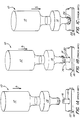
- FIG. 1A-1C a typical ultrasonic staking operation is schematically shown.
- An ultrasonic stack 10, including a converter 12 and a horn 14, is moveable with respect to the axis of a post 16 protruding from a first plastic part 18 and through a hole 20 in a second plastic part 22.
- the first plastic part 18 and the second plastic part 22 are to be joined together by ultrasonic staking.
- the ultrasonic stack 10 is being moved downward (indicated by arrow A), but the horn 14 has not yet made contact with the post 16. Ultrasonic vibrations are being provided to the horn 14, but since it has not yet contacted the post 16, no resistance is being met and no pressure is being applied to the post 16. As such, the power required to vibrate the horn 14 is very low.
- the upper surface of the second plastic part 22 be partially melted so that a "witness ring" 26 is formed, the presence of which indicates that a tight bond has been created.
- the area of contact at the end of the horn 14 increases dramatically, thereby dramatically increasing the resistance met thereby, and consequently greatly increasing the power required to maintain the ultrasonic vibrations of the horn 14. It is at this point where the potential exists for overloading of the power supply.
- the overloads are real because the power required advances drastically at the very end of the weld timing.
- the increased power is related to the ultrasonic horn design for this particular type of application. As the horn melts the stake post and approaches the surface, the outer edge of the horn will contact the surface of the attached parts and increase the area of applied force. This increased area at the same advancing speed will increase the power above the overload protection setting.
- Figures 1A-1C are representative of a horn design that would force a power change requirement as the weld progresses.
- Air cylinder systems or other types of motion system would have the same type of impact by actively changing the pressure. Air would not have the same level of force control because of the cylinder volume but the effect could still be used to a lesser result.
- use of a stepper motor to control travel of the stack 10 is preferred.
- the hydraulic nature of the sealed molten material and the horn 14 against the top surface of the second plastic part 22 allows a very rapid force change with the motor speed change.
- FIG. 2A and 2B the problem of power overloading using prior art systems as the stack 10 (converter 12 and horn 14 assembly) is moved at constant velocity (as illustrated in Figure 2B which shows linear distance versus time) through the weld is graphically shown.
- the power required is essentially zero until the horn 14 contacts the post 16 (indicated at P1), at which time there is an increased power requirement until the post 16 begins to melt.
- the power required substantially reaches a plateau (indicated by P2) as the stack 10 is moved downward and the post 14 continues to melt. This continues until the horn 14 contacts the surface of the second part 22 (indicated by P3), at which point the required power increases dramatically to the overload limit (indicated by P4) and the power supply is shut down.
- the shutdown protects the supply from internal damage but does abort the weld cycle even though it occurs at the very end of the desired weld time so it appears as a completed, good weld.
- Quality control tends to use the "witness ring" appearance as an acceptable weld.
- This witness ring is the mark left in the top surface as the outer edge of the horn touches the part melting a ring shaped pattern. It is desirable to see this pattern as verification that the horn traveled all the way to the part capturing the pieces together properly. Such may not occur, however, when the power supply is shut down using a scheme of overload protection where the power supply is shut down.
- FIG. 3A and 3B show the result of reducing the travel speed and the direct effect on the applied power. This allows a low wattage supply to be used for the staking application.
- Figure 4 schematically shows a system for implementing the scheme shown in Figures 3A and 3B .
- the weld can be terminated at contact or shortly afterward to make a proper witness ring or continue at the slower speed to a specific depth. Moreover, the speed used for melting the post can be increased to reduce the time and compensate for the slower speed at the end of the weld, thereby allowing the weld to be created in the same time, or even a shorter time, as compared to prior art systems.
- the detection level must be between the power level used for melting the post 16 (indicated by P2 in Figures 2A and 3A ) and the overload level (indicated by P4 in Figure 2A ). Detection must happen quickly enough so that the output detect signal can be used by the motion or pressure control 30 to reduce the speed of the stepper motor 32 quickly enough to prevent the power from getting to the overload level.
- This detect setpoint (indicated by P5 in Figure 3A ) is determined through experimentation with the horns, materials, speeds and ultrasonic amplitude settings.
- the function of the detector 34 may be implemented, for example, by a comparator on the ultrasonic power supply 36, although other mechanisms for detection are also possible.
- the detector output 38 indicates that the power has climbed above the setpoint and the stepper motor system should use a reduced speed (indicated by P6 in Figure 3B ) for the remainder of the weld cycle. As shown in Figure 3A , this reduced speed causes a corresponding drop in the power level requirements of the power supply, such that the sharp spike resulting in power overload (shown in Figure 2A ) never occurs.
- This detector 34 may be configured with an adjustable trip point (indicated by P5), which enables the power level to be set to best match the particular application at hand.
- the detector output 38 is used by the motion control system 30 to slow the advance of the stack 10 and reduce the rate at which the power is increasing in time to prevent any overload tendencies.
- Another benefit of this technique is that the distance for each post to be welded does not need to be determined. It is only necessary that the travel setting be farther than the longest weld.
- the system can be set to terminate at contact so the PLC control requirements are reduced to shutting off ultrasonics as soon as possible after contact. The result is faster welds at reduced time with a lower wattage power supply.
Landscapes
- Engineering & Computer Science (AREA)
- Mechanical Engineering (AREA)
- Pressure Welding/Diffusion-Bonding (AREA)
- Lining Or Joining Of Plastics Or The Like (AREA)
- Apparatuses For Generation Of Mechanical Vibrations (AREA)
Claims (12)
- Système pour effectuer une opération d'empilement ultrasonore afin de joindre une première partie ayant un montant faisant saillie à partir de celle-ci et une seconde partie ayant un trou à travers lequel le montant passe, ledit système comprenant :un pavillon ayant une extrémité vibrant à une fréquence dans la plage des ultrasons ;une alimentation électrique qui fournit l'énergie nécessaire pour provoquer les vibrations ultrasonores de l'extrémité dudit pavillon ;un système de déplacement relié de façon fonctionnelle audit pavillon, ledit système de déplacement étant capable de déplacer sélectivement ledit pavillon vers et à l'écart des première et seconde parties ;caractérisé en ce que :ledit système de déplacement déplace ledit pavillon, avec l'extrémité dudit pavillon en contact avec le montant, vers les première et seconde parties à une première vitesse de telle manière que les vibrations ultrasonores de l'extrémité dudit pavillon provoquent la fonte du montant ; etune fois qu'il a été déterminé que l'extrémité dudit pavillon est entrée en contact avec une surface de la seconde partie entourant le trou, ledit système de déplacement déplace ledit pavillon vers les première et seconde parties à une seconde vitesse, la seconde vitesse étant plus lente que la première vitesse.
- Système selon la revendication 1 dans lequel la détermination que l'extrémité dudit pavillon est entrée en contact avec une surface de la seconde partie entourant le trou est réalisée sur la base d'un niveau d'énergie requis de l'alimentation électrique afin de maintenir les vibrations ultrasonores de l'extrémité dudit pavillon.
- Système selon la revendication 2 dans lequel la détermination que l'extrémité dudit pavillon est entrée en contact avec une surface de la seconde partie entourant le trou est réalisée lorsque le niveau d'énergie requis de l'alimentation électrique afin de maintenir les vibrations ultrasonores de l'extrémité dudit pavillon est supérieur à une valeur seuil.
- Système selon la revendication 3 dans lequel la valeur seuil peut être modifiée par un utilisateur dudit système.
- Système selon la revendication 2 dans lequel ladite alimentation électrique comprend un détecteur de puissance et dans lequel la détermination que l'extrémité dudit pavillon est entrée en contact avec une surface de la seconde partie entourant le trou est réalisée par ledit détecteur de puissance.
- Système selon la revendication 5 dans lequel ledit détecteur de puissance comprend un comparateur.
- Système selon la revendication 1 dans lequel ledit système de déplacement comprend un moteur pas à pas.
- Système selon la revendication 1 dans lequel l'amplitude et la fréquence des vibrations ultrasonores de l'extrémité dudit pavillon sont maintenues sensiblement constantes durant une intégralité de l'opération d'empilement ultrasonore.
- Procédé pour effectuer une opération d'empilement ultrasonore afin de joindre une première partie ayant un montant faisant saillie à partir de celle-ci et une seconde partie ayant un trou à travers lequel le montant passe, ledit procédé comprenant les étapes de :vibration d'une extrémité d'un pavillon à une fréquence dans la plage des ultrasons, par fourniture de l'énergie nécessaire à l'aide d'une alimentation électrique ;caractérisé en ce que le procédé comprend en outre les étapes de :déplacement du pavillon, avec l'extrémité du pavillon en contact avec le montant, vers les première et seconde parties à une première vitesse de telle manière que les vibrations ultrasonores de l'extrémité du pavillon provoquent la fonte du montant ;détermination du moment où l'extrémité du pavillon est entrée en contact avec une surface de la seconde partie entourant le trou ; etdéplacement, une fois qu'il a été déterminé que l'extrémité du pavillon est entrée en contact avec une surface de la seconde partie entourant le trou, du pavillon vers les première et seconde parties à une seconde vitesse, la seconde vitesse étant plus lente que la première vitesse.
- Procédé selon la revendication 9 dans lequel l'étape de détermination est effectuée sur la base d'un niveau d'énergie requis de l'alimentation électrique afin d'effectuer l'étape de vibration.
- Procédé selon la revendication 10 dans lequel l'étape de détermination comprend l'étape de détermination du moment où le niveau d'énergie requis de l'alimentation électrique afin d'effectuer l'étape de vibration est supérieur à une valeur seuil.
- Procédé selon la revendication 11 dans lequel l'étape de vibration comprend l'étape de vibration d'une extrémité d'un pavillon à une fréquence dans la plage des ultrasons ayant une amplitude et une fréquence qui sont maintenues sensiblement constantes durant une intégralité de l'opération d'empilement ultrasonore.
Applications Claiming Priority (2)
| Application Number | Priority Date | Filing Date | Title |
|---|---|---|---|
| US5002308P | 2008-05-02 | 2008-05-02 | |
| PCT/US2009/002751 WO2009134458A1 (fr) | 2008-05-02 | 2009-05-04 | Système pour empêcher des surcharges pour des applications d'empilement ultrasonore |
Publications (3)
| Publication Number | Publication Date |
|---|---|
| EP2285520A1 EP2285520A1 (fr) | 2011-02-23 |
| EP2285520A4 EP2285520A4 (fr) | 2016-12-28 |
| EP2285520B1 true EP2285520B1 (fr) | 2019-01-02 |
Family
ID=41255338
Family Applications (1)
| Application Number | Title | Priority Date | Filing Date |
|---|---|---|---|
| EP09739261.7A Active EP2285520B1 (fr) | 2008-05-02 | 2009-05-04 | Système pour empêcher des surcharges pour des applications de rivetage par ultrasons |
Country Status (4)
| Country | Link |
|---|---|
| US (1) | US8016964B2 (fr) |
| EP (1) | EP2285520B1 (fr) |
| CA (1) | CA2722921C (fr) |
| WO (1) | WO2009134458A1 (fr) |
Families Citing this family (10)
| Publication number | Priority date | Publication date | Assignee | Title |
|---|---|---|---|---|
| JP4080492B2 (ja) * | 2005-03-31 | 2008-04-23 | 日本発条株式会社 | 接合体および接合方法 |
| JP5284835B2 (ja) * | 2009-03-17 | 2013-09-11 | オリンパス株式会社 | 部材同士の固定方法 |
| US9981337B2 (en) | 2014-05-13 | 2018-05-29 | Sonics & Materials, Inc. | Diagnostic system and method for testing integrity of stack during ultrasonic welding |
| WO2017159329A1 (fr) * | 2016-03-18 | 2017-09-21 | 本田技研工業株式会社 | Dispositif de soudage par ultrasons et procédé de soudage par ultrasons |
| US20180186084A1 (en) * | 2016-07-26 | 2018-07-05 | T.A. Systems, Inc. | Method and apparatus for ultrasonic welding |
| GB2553296A (en) * | 2016-08-26 | 2018-03-07 | Ford Global Tech Llc | Improvements in or relating to heat stakes |
| US20190299310A1 (en) * | 2018-03-30 | 2019-10-03 | Branson Ultrasonics Corporation | Contact Detection Based On Frequency In Ultrasonics |
| US10746703B2 (en) * | 2018-11-13 | 2020-08-18 | Dukane Ias, Llc | Automated ultrasonic press systems and methods for welding physically variant components |
| US10549481B1 (en) * | 2018-12-21 | 2020-02-04 | Dukane Ias, Llc | Systems and methods for low initial weld speed in ultrasonic welding |
| JP2023527970A (ja) * | 2020-06-03 | 2023-07-03 | クリック アンド ソッファ インダストリーズ、インク. | 超音波溶接システム、その使用方法、および溶接された導電性ピンを含む関連被加工物 |
Family Cites Families (19)
| Publication number | Priority date | Publication date | Assignee | Title |
|---|---|---|---|---|
| US3784079A (en) * | 1972-04-03 | 1974-01-08 | Motorola Inc | Ultrasonic bond control apparatus |
| US4746051A (en) * | 1982-12-08 | 1988-05-24 | General Motors Corporation | Ultrasonic welding control |
| US4631685A (en) * | 1984-12-07 | 1986-12-23 | General Motors Corporation | Method and apparatus for ultrasonic plastic forming and joining |
| US4859378A (en) * | 1988-10-28 | 1989-08-22 | Branson Ultrasonics Corporation | Method of ultrasonically assembling workpieces |
| US4865687A (en) * | 1988-12-23 | 1989-09-12 | Eastman Kodak Company | Ultrasonic securing method |
| US4865680A (en) * | 1988-12-23 | 1989-09-12 | Eastman Kodak Company | Ultrasonic securing system |
| EP0421019B1 (fr) * | 1989-10-06 | 1994-01-19 | Siemens Aktiengesellschaft | Méthode et dispositif de jointure d'éléments en matière plastique par ultrasons |
| US5085719A (en) * | 1990-09-14 | 1992-02-04 | Xerox Corporation | Variable rate welding of thermoplastic belts |
| US5366580A (en) * | 1992-01-08 | 1994-11-22 | Cosmos Electronic Machine Corp. | High frequency welding machine |
| US5658408A (en) * | 1992-04-21 | 1997-08-19 | Branson Ultrasonics Corporation | Method for processing workpieces by ultrasonic energy |
| DE567426T1 (de) * | 1992-04-21 | 1994-02-03 | Emerson Electric Co | Verfahren und Gerät zur Werkstückbearbeitung mit Ultraschallenergie. |
| US5213249A (en) * | 1992-05-29 | 1993-05-25 | International Business Machines Corporation | Ultrasonic adhesion/dehesion monitoring apparatus with power feedback measuring means |
| DE4400210A1 (de) * | 1994-01-05 | 1995-08-10 | Branson Ultraschall | Verfahren und Einrichtung zum Betrieb eines Generators zur HF-Energieversorgung eines Ultraschallwandlers |
| JP3789178B2 (ja) * | 1996-11-19 | 2006-06-21 | 株式会社アズマ工機 | 熱かしめ装置 |
| IT1301867B1 (it) * | 1998-07-24 | 2000-07-07 | P S I Pipeline Service Sa | Dispositivo mobile per la saldatura automatica di condutture |
| DE10046451A1 (de) * | 2000-09-18 | 2002-03-28 | Spaichingen Gmbh Maschf | Verfahren und Vorrichtung zum Ultraschallschweißen von Werkstücken |
| US7225965B2 (en) * | 2003-09-22 | 2007-06-05 | Dukane Corporation | Multiple probe power systems and methods for ultrasonic welding |
| RU2006147217A (ru) * | 2005-12-29 | 2008-07-10 | Дюкейн Корпорейшн (Us) | Системы для подвода регулируемой мощности к головкам для ультразвуковой сварки |
| US20080054051A1 (en) * | 2006-09-01 | 2008-03-06 | Branson Ultrasonics Corporation | Ultrasonic Welding Using Amplitude Profiling |
-
2009
- 2009-05-04 EP EP09739261.7A patent/EP2285520B1/fr active Active
- 2009-05-04 WO PCT/US2009/002751 patent/WO2009134458A1/fr active Application Filing
- 2009-05-04 CA CA2722921A patent/CA2722921C/fr active Active
- 2009-05-04 US US12/434,818 patent/US8016964B2/en active Active
Non-Patent Citations (1)
| Title |
|---|
| None * |
Also Published As
| Publication number | Publication date |
|---|---|
| CA2722921A1 (fr) | 2009-11-05 |
| EP2285520A1 (fr) | 2011-02-23 |
| EP2285520A4 (fr) | 2016-12-28 |
| US8016964B2 (en) | 2011-09-13 |
| CA2722921C (fr) | 2013-04-30 |
| WO2009134458A1 (fr) | 2009-11-05 |
| US20090272480A1 (en) | 2009-11-05 |
Similar Documents
| Publication | Publication Date | Title |
|---|---|---|
| EP2285520B1 (fr) | Système pour empêcher des surcharges pour des applications de rivetage par ultrasons | |
| US9688017B2 (en) | Vibration welders with high frequency vibration, position motion control, and delayed weld motion | |
| EP0567426B1 (fr) | Procédé de soudage ultrasonore | |
| JP6685669B2 (ja) | サーボモータおよび遅延運動手法を使用した超音波プレス機 | |
| JPH0270392A (ja) | 摩擦溶接の機械的パラメーターを制御する方法 | |
| GB2332636A (en) | Welding control | |
| US6588644B2 (en) | Energy controller for vibration welder | |
| JP6339292B2 (ja) | スポット溶接方法及びその装置 | |
| JPH06277845A (ja) | アーク溶接装置のアーク溶接方法 | |
| KR100602200B1 (ko) | 하이브리드 용접 제어장치 | |
| EP3898202B1 (fr) | Procédé pour une vitesse de soudure initiale basse dans un soudage par ultrasons | |
| US11833764B2 (en) | Ultrasonic treatment method | |
| JPH1140416A (ja) | ソレノイド駆動装置 | |
| CN115138935B (zh) | 焊接装置和焊接装置的控制方法 | |
| EP3925763A1 (fr) | Unité de soudage par ultrasons | |
| KR100467220B1 (ko) | 맞대기 이음용 자동 용접장치의 용접주행 속도제어방법 | |
| WO2016157946A1 (fr) | Dispositif et procédé pour fabriquer un dispositif de commande de volume d'écoulement | |
| JPH1085948A (ja) | スポット溶接制御装置 | |
| JP2001314977A (ja) | マッシュシーム溶接方法と装置 | |
| JP2006142307A (ja) | エキスパンドメタルのプロジェクション溶接方法 | |
| JPH11104888A (ja) | 溶接装置および溶接方法 | |
| CN114178673A (zh) | 一种基于伺服电机压力控制的焊接方法及系统 | |
| JP2006142380A (ja) | 抵抗プロジェクション溶接機 | |
| JPH09108835A (ja) | 電気溶接のタッチスタート方法 | |
| JP2001138061A (ja) | 加圧力から溶接電流を決定する抵抗溶接装置と溶接方法 |
Legal Events
| Date | Code | Title | Description |
|---|---|---|---|
| PUAI | Public reference made under article 153(3) epc to a published international application that has entered the european phase |
Free format text: ORIGINAL CODE: 0009012 |
|
| 17P | Request for examination filed |
Effective date: 20101029 |
|
| AK | Designated contracting states |
Kind code of ref document: A1 Designated state(s): AT BE BG CH CY CZ DE DK EE ES FI FR GB GR HR HU IE IS IT LI LT LU LV MC MK MT NL NO PL PT RO SE SI SK TR |
|
| AX | Request for extension of the european patent |
Extension state: AL BA RS |
|
| DAX | Request for extension of the european patent (deleted) | ||
| REG | Reference to a national code |
Ref country code: DE Ref legal event code: R079 Ref document number: 602009056507 Country of ref document: DE Free format text: PREVIOUS MAIN CLASS: B23K0001060000 Ipc: B29C0065080000 |
|
| RA4 | Supplementary search report drawn up and despatched (corrected) |
Effective date: 20161124 |
|
| RIC1 | Information provided on ipc code assigned before grant |
Ipc: B29C 65/60 20060101ALI20161118BHEP Ipc: B29C 65/08 20060101AFI20161118BHEP Ipc: B23K 1/06 20060101ALI20161118BHEP |
|
| GRAP | Despatch of communication of intention to grant a patent |
Free format text: ORIGINAL CODE: EPIDOSNIGR1 |
|
| STAA | Information on the status of an ep patent application or granted ep patent |
Free format text: STATUS: GRANT OF PATENT IS INTENDED |
|
| INTG | Intention to grant announced |
Effective date: 20180810 |
|
| GRAS | Grant fee paid |
Free format text: ORIGINAL CODE: EPIDOSNIGR3 |
|
| GRAA | (expected) grant |
Free format text: ORIGINAL CODE: 0009210 |
|
| STAA | Information on the status of an ep patent application or granted ep patent |
Free format text: STATUS: THE PATENT HAS BEEN GRANTED |
|
| AK | Designated contracting states |
Kind code of ref document: B1 Designated state(s): AT BE BG CH CY CZ DE DK EE ES FI FR GB GR HR HU IE IS IT LI LT LU LV MC MK MT NL NO PL PT RO SE SI SK TR |
|
| REG | Reference to a national code |
Ref country code: GB Ref legal event code: FG4D |
|
| REG | Reference to a national code |
Ref country code: CH Ref legal event code: EP Ref country code: AT Ref legal event code: REF Ref document number: 1083801 Country of ref document: AT Kind code of ref document: T Effective date: 20190115 |
|
| REG | Reference to a national code |
Ref country code: DE Ref legal event code: R096 Ref document number: 602009056507 Country of ref document: DE |
|
| REG | Reference to a national code |
Ref country code: IE Ref legal event code: FG4D |
|
| REG | Reference to a national code |
Ref country code: NL Ref legal event code: MP Effective date: 20190102 |
|
| REG | Reference to a national code |
Ref country code: LT Ref legal event code: MG4D |
|
| REG | Reference to a national code |
Ref country code: AT Ref legal event code: MK05 Ref document number: 1083801 Country of ref document: AT Kind code of ref document: T Effective date: 20190102 |
|
| PG25 | Lapsed in a contracting state [announced via postgrant information from national office to epo] |
Ref country code: NL Free format text: LAPSE BECAUSE OF FAILURE TO SUBMIT A TRANSLATION OF THE DESCRIPTION OR TO PAY THE FEE WITHIN THE PRESCRIBED TIME-LIMIT Effective date: 20190102 |
|
| PG25 | Lapsed in a contracting state [announced via postgrant information from national office to epo] |
Ref country code: FI Free format text: LAPSE BECAUSE OF FAILURE TO SUBMIT A TRANSLATION OF THE DESCRIPTION OR TO PAY THE FEE WITHIN THE PRESCRIBED TIME-LIMIT Effective date: 20190102 Ref country code: NO Free format text: LAPSE BECAUSE OF FAILURE TO SUBMIT A TRANSLATION OF THE DESCRIPTION OR TO PAY THE FEE WITHIN THE PRESCRIBED TIME-LIMIT Effective date: 20190402 Ref country code: PT Free format text: LAPSE BECAUSE OF FAILURE TO SUBMIT A TRANSLATION OF THE DESCRIPTION OR TO PAY THE FEE WITHIN THE PRESCRIBED TIME-LIMIT Effective date: 20190502 Ref country code: SE Free format text: LAPSE BECAUSE OF FAILURE TO SUBMIT A TRANSLATION OF THE DESCRIPTION OR TO PAY THE FEE WITHIN THE PRESCRIBED TIME-LIMIT Effective date: 20190102 Ref country code: LT Free format text: LAPSE BECAUSE OF FAILURE TO SUBMIT A TRANSLATION OF THE DESCRIPTION OR TO PAY THE FEE WITHIN THE PRESCRIBED TIME-LIMIT Effective date: 20190102 Ref country code: ES Free format text: LAPSE BECAUSE OF FAILURE TO SUBMIT A TRANSLATION OF THE DESCRIPTION OR TO PAY THE FEE WITHIN THE PRESCRIBED TIME-LIMIT Effective date: 20190102 Ref country code: PL Free format text: LAPSE BECAUSE OF FAILURE TO SUBMIT A TRANSLATION OF THE DESCRIPTION OR TO PAY THE FEE WITHIN THE PRESCRIBED TIME-LIMIT Effective date: 20190102 |
|
| PG25 | Lapsed in a contracting state [announced via postgrant information from national office to epo] |
Ref country code: HR Free format text: LAPSE BECAUSE OF FAILURE TO SUBMIT A TRANSLATION OF THE DESCRIPTION OR TO PAY THE FEE WITHIN THE PRESCRIBED TIME-LIMIT Effective date: 20190102 Ref country code: BG Free format text: LAPSE BECAUSE OF FAILURE TO SUBMIT A TRANSLATION OF THE DESCRIPTION OR TO PAY THE FEE WITHIN THE PRESCRIBED TIME-LIMIT Effective date: 20190402 Ref country code: GR Free format text: LAPSE BECAUSE OF FAILURE TO SUBMIT A TRANSLATION OF THE DESCRIPTION OR TO PAY THE FEE WITHIN THE PRESCRIBED TIME-LIMIT Effective date: 20190403 Ref country code: LV Free format text: LAPSE BECAUSE OF FAILURE TO SUBMIT A TRANSLATION OF THE DESCRIPTION OR TO PAY THE FEE WITHIN THE PRESCRIBED TIME-LIMIT Effective date: 20190102 Ref country code: IS Free format text: LAPSE BECAUSE OF FAILURE TO SUBMIT A TRANSLATION OF THE DESCRIPTION OR TO PAY THE FEE WITHIN THE PRESCRIBED TIME-LIMIT Effective date: 20190502 |
|
| REG | Reference to a national code |
Ref country code: DE Ref legal event code: R097 Ref document number: 602009056507 Country of ref document: DE |
|
| PG25 | Lapsed in a contracting state [announced via postgrant information from national office to epo] |
Ref country code: EE Free format text: LAPSE BECAUSE OF FAILURE TO SUBMIT A TRANSLATION OF THE DESCRIPTION OR TO PAY THE FEE WITHIN THE PRESCRIBED TIME-LIMIT Effective date: 20190102 Ref country code: SK Free format text: LAPSE BECAUSE OF FAILURE TO SUBMIT A TRANSLATION OF THE DESCRIPTION OR TO PAY THE FEE WITHIN THE PRESCRIBED TIME-LIMIT Effective date: 20190102 Ref country code: IT Free format text: LAPSE BECAUSE OF FAILURE TO SUBMIT A TRANSLATION OF THE DESCRIPTION OR TO PAY THE FEE WITHIN THE PRESCRIBED TIME-LIMIT Effective date: 20190102 Ref country code: AT Free format text: LAPSE BECAUSE OF FAILURE TO SUBMIT A TRANSLATION OF THE DESCRIPTION OR TO PAY THE FEE WITHIN THE PRESCRIBED TIME-LIMIT Effective date: 20190102 Ref country code: DK Free format text: LAPSE BECAUSE OF FAILURE TO SUBMIT A TRANSLATION OF THE DESCRIPTION OR TO PAY THE FEE WITHIN THE PRESCRIBED TIME-LIMIT Effective date: 20190102 Ref country code: CZ Free format text: LAPSE BECAUSE OF FAILURE TO SUBMIT A TRANSLATION OF THE DESCRIPTION OR TO PAY THE FEE WITHIN THE PRESCRIBED TIME-LIMIT Effective date: 20190102 Ref country code: RO Free format text: LAPSE BECAUSE OF FAILURE TO SUBMIT A TRANSLATION OF THE DESCRIPTION OR TO PAY THE FEE WITHIN THE PRESCRIBED TIME-LIMIT Effective date: 20190102 |
|
| PLBE | No opposition filed within time limit |
Free format text: ORIGINAL CODE: 0009261 |
|
| STAA | Information on the status of an ep patent application or granted ep patent |
Free format text: STATUS: NO OPPOSITION FILED WITHIN TIME LIMIT |
|
| 26N | No opposition filed |
Effective date: 20191003 |
|
| REG | Reference to a national code |
Ref country code: CH Ref legal event code: PL |
|
| PG25 | Lapsed in a contracting state [announced via postgrant information from national office to epo] |
Ref country code: CH Free format text: LAPSE BECAUSE OF NON-PAYMENT OF DUE FEES Effective date: 20190531 Ref country code: LI Free format text: LAPSE BECAUSE OF NON-PAYMENT OF DUE FEES Effective date: 20190531 Ref country code: MC Free format text: LAPSE BECAUSE OF FAILURE TO SUBMIT A TRANSLATION OF THE DESCRIPTION OR TO PAY THE FEE WITHIN THE PRESCRIBED TIME-LIMIT Effective date: 20190102 |
|
| REG | Reference to a national code |
Ref country code: BE Ref legal event code: MM Effective date: 20190531 |
|
| PG25 | Lapsed in a contracting state [announced via postgrant information from national office to epo] |
Ref country code: LU Free format text: LAPSE BECAUSE OF NON-PAYMENT OF DUE FEES Effective date: 20190504 Ref country code: SI Free format text: LAPSE BECAUSE OF FAILURE TO SUBMIT A TRANSLATION OF THE DESCRIPTION OR TO PAY THE FEE WITHIN THE PRESCRIBED TIME-LIMIT Effective date: 20190102 |
|
| PG25 | Lapsed in a contracting state [announced via postgrant information from national office to epo] |
Ref country code: TR Free format text: LAPSE BECAUSE OF FAILURE TO SUBMIT A TRANSLATION OF THE DESCRIPTION OR TO PAY THE FEE WITHIN THE PRESCRIBED TIME-LIMIT Effective date: 20190102 |
|
| PG25 | Lapsed in a contracting state [announced via postgrant information from national office to epo] |
Ref country code: IE Free format text: LAPSE BECAUSE OF NON-PAYMENT OF DUE FEES Effective date: 20190504 |
|
| PG25 | Lapsed in a contracting state [announced via postgrant information from national office to epo] |
Ref country code: BE Free format text: LAPSE BECAUSE OF NON-PAYMENT OF DUE FEES Effective date: 20190531 |
|
| PG25 | Lapsed in a contracting state [announced via postgrant information from national office to epo] |
Ref country code: CY Free format text: LAPSE BECAUSE OF FAILURE TO SUBMIT A TRANSLATION OF THE DESCRIPTION OR TO PAY THE FEE WITHIN THE PRESCRIBED TIME-LIMIT Effective date: 20190102 |
|
| PG25 | Lapsed in a contracting state [announced via postgrant information from national office to epo] |
Ref country code: HU Free format text: LAPSE BECAUSE OF FAILURE TO SUBMIT A TRANSLATION OF THE DESCRIPTION OR TO PAY THE FEE WITHIN THE PRESCRIBED TIME-LIMIT; INVALID AB INITIO Effective date: 20090504 Ref country code: MT Free format text: LAPSE BECAUSE OF FAILURE TO SUBMIT A TRANSLATION OF THE DESCRIPTION OR TO PAY THE FEE WITHIN THE PRESCRIBED TIME-LIMIT Effective date: 20190102 |
|
| PG25 | Lapsed in a contracting state [announced via postgrant information from national office to epo] |
Ref country code: MK Free format text: LAPSE BECAUSE OF FAILURE TO SUBMIT A TRANSLATION OF THE DESCRIPTION OR TO PAY THE FEE WITHIN THE PRESCRIBED TIME-LIMIT Effective date: 20190102 |
|
| PGFP | Annual fee paid to national office [announced via postgrant information from national office to epo] |
Ref country code: GB Payment date: 20240320 Year of fee payment: 16 |
|
| PGFP | Annual fee paid to national office [announced via postgrant information from national office to epo] |
Ref country code: FR Payment date: 20240320 Year of fee payment: 16 |
|
| PGFP | Annual fee paid to national office [announced via postgrant information from national office to epo] |
Ref country code: DE Payment date: 20240325 Year of fee payment: 16 |