EP2284545A2 - Koplanare seismische Massen zur Bestimmung der Beschleunigung entlang drei Achsen - Google Patents
Koplanare seismische Massen zur Bestimmung der Beschleunigung entlang drei Achsen Download PDFInfo
- Publication number
- EP2284545A2 EP2284545A2 EP10181392A EP10181392A EP2284545A2 EP 2284545 A2 EP2284545 A2 EP 2284545A2 EP 10181392 A EP10181392 A EP 10181392A EP 10181392 A EP10181392 A EP 10181392A EP 2284545 A2 EP2284545 A2 EP 2284545A2
- Authority
- EP
- European Patent Office
- Prior art keywords
- proofmass
- proofmasses
- employable
- sense
- acceleration
- Prior art date
- Legal status (The legal status is an assumption and is not a legal conclusion. Google has not performed a legal analysis and makes no representation as to the accuracy of the status listed.)
- Granted
Links
- 230000001133 acceleration Effects 0.000 title claims abstract description 81
- 239000000758 substrate Substances 0.000 claims description 12
- 238000000034 method Methods 0.000 claims description 11
- 238000005530 etching Methods 0.000 claims description 8
- 238000005259 measurement Methods 0.000 claims description 6
- 238000013016 damping Methods 0.000 claims description 4
- XUIMIQQOPSSXEZ-UHFFFAOYSA-N Silicon Chemical compound [Si] XUIMIQQOPSSXEZ-UHFFFAOYSA-N 0.000 description 7
- 229910052710 silicon Inorganic materials 0.000 description 7
- 239000010703 silicon Substances 0.000 description 7
- 238000006073 displacement reaction Methods 0.000 description 5
- 238000004364 calculation method Methods 0.000 description 3
- 238000013461 design Methods 0.000 description 3
- 235000012431 wafers Nutrition 0.000 description 3
- VYPSYNLAJGMNEJ-UHFFFAOYSA-N Silicium dioxide Chemical compound O=[Si]=O VYPSYNLAJGMNEJ-UHFFFAOYSA-N 0.000 description 2
- 229910021421 monocrystalline silicon Inorganic materials 0.000 description 2
- 238000012545 processing Methods 0.000 description 2
- 239000000725 suspension Substances 0.000 description 2
- 238000012546 transfer Methods 0.000 description 2
- 238000013519 translation Methods 0.000 description 2
- 238000007792 addition Methods 0.000 description 1
- 238000004458 analytical method Methods 0.000 description 1
- 239000003990 capacitor Substances 0.000 description 1
- 238000005516 engineering process Methods 0.000 description 1
- 239000012212 insulator Substances 0.000 description 1
- 238000004519 manufacturing process Methods 0.000 description 1
- 238000005459 micromachining Methods 0.000 description 1
- 238000012986 modification Methods 0.000 description 1
- 230000004048 modification Effects 0.000 description 1
- 235000012239 silicon dioxide Nutrition 0.000 description 1
- 239000000377 silicon dioxide Substances 0.000 description 1
- 230000005476 size effect Effects 0.000 description 1
- 229910000679 solder Inorganic materials 0.000 description 1
- 238000006467 substitution reaction Methods 0.000 description 1
- 238000007514 turning Methods 0.000 description 1
Images


Classifications
-
- G—PHYSICS
- G01—MEASURING; TESTING
- G01P—MEASURING LINEAR OR ANGULAR SPEED, ACCELERATION, DECELERATION, OR SHOCK; INDICATING PRESENCE, ABSENCE, OR DIRECTION, OF MOVEMENT
- G01P15/00—Measuring acceleration; Measuring deceleration; Measuring shock, i.e. sudden change of acceleration
- G01P15/18—Measuring acceleration; Measuring deceleration; Measuring shock, i.e. sudden change of acceleration in two or more dimensions
-
- G—PHYSICS
- G01—MEASURING; TESTING
- G01P—MEASURING LINEAR OR ANGULAR SPEED, ACCELERATION, DECELERATION, OR SHOCK; INDICATING PRESENCE, ABSENCE, OR DIRECTION, OF MOVEMENT
- G01P15/00—Measuring acceleration; Measuring deceleration; Measuring shock, i.e. sudden change of acceleration
- G01P15/02—Measuring acceleration; Measuring deceleration; Measuring shock, i.e. sudden change of acceleration by making use of inertia forces using solid seismic masses
- G01P15/08—Measuring acceleration; Measuring deceleration; Measuring shock, i.e. sudden change of acceleration by making use of inertia forces using solid seismic masses with conversion into electric or magnetic values
- G01P15/0802—Details
-
- G—PHYSICS
- G01—MEASURING; TESTING
- G01P—MEASURING LINEAR OR ANGULAR SPEED, ACCELERATION, DECELERATION, OR SHOCK; INDICATING PRESENCE, ABSENCE, OR DIRECTION, OF MOVEMENT
- G01P15/00—Measuring acceleration; Measuring deceleration; Measuring shock, i.e. sudden change of acceleration
- G01P15/02—Measuring acceleration; Measuring deceleration; Measuring shock, i.e. sudden change of acceleration by making use of inertia forces using solid seismic masses
- G01P15/08—Measuring acceleration; Measuring deceleration; Measuring shock, i.e. sudden change of acceleration by making use of inertia forces using solid seismic masses with conversion into electric or magnetic values
- G01P15/125—Measuring acceleration; Measuring deceleration; Measuring shock, i.e. sudden change of acceleration by making use of inertia forces using solid seismic masses with conversion into electric or magnetic values by capacitive pick-up
-
- G—PHYSICS
- G01—MEASURING; TESTING
- G01P—MEASURING LINEAR OR ANGULAR SPEED, ACCELERATION, DECELERATION, OR SHOCK; INDICATING PRESENCE, ABSENCE, OR DIRECTION, OF MOVEMENT
- G01P15/00—Measuring acceleration; Measuring deceleration; Measuring shock, i.e. sudden change of acceleration
- G01P15/02—Measuring acceleration; Measuring deceleration; Measuring shock, i.e. sudden change of acceleration by making use of inertia forces using solid seismic masses
- G01P15/08—Measuring acceleration; Measuring deceleration; Measuring shock, i.e. sudden change of acceleration by making use of inertia forces using solid seismic masses with conversion into electric or magnetic values
- G01P2015/0805—Measuring acceleration; Measuring deceleration; Measuring shock, i.e. sudden change of acceleration by making use of inertia forces using solid seismic masses with conversion into electric or magnetic values being provided with a particular type of spring-mass-system for defining the displacement of a seismic mass due to an external acceleration
- G01P2015/0822—Measuring acceleration; Measuring deceleration; Measuring shock, i.e. sudden change of acceleration by making use of inertia forces using solid seismic masses with conversion into electric or magnetic values being provided with a particular type of spring-mass-system for defining the displacement of a seismic mass due to an external acceleration for defining out-of-plane movement of the mass
- G01P2015/0825—Measuring acceleration; Measuring deceleration; Measuring shock, i.e. sudden change of acceleration by making use of inertia forces using solid seismic masses with conversion into electric or magnetic values being provided with a particular type of spring-mass-system for defining the displacement of a seismic mass due to an external acceleration for defining out-of-plane movement of the mass for one single degree of freedom of movement of the mass
- G01P2015/0828—Measuring acceleration; Measuring deceleration; Measuring shock, i.e. sudden change of acceleration by making use of inertia forces using solid seismic masses with conversion into electric or magnetic values being provided with a particular type of spring-mass-system for defining the displacement of a seismic mass due to an external acceleration for defining out-of-plane movement of the mass for one single degree of freedom of movement of the mass the mass being of the paddle type being suspended at one of its longitudinal ends
-
- G—PHYSICS
- G01—MEASURING; TESTING
- G01P—MEASURING LINEAR OR ANGULAR SPEED, ACCELERATION, DECELERATION, OR SHOCK; INDICATING PRESENCE, ABSENCE, OR DIRECTION, OF MOVEMENT
- G01P15/00—Measuring acceleration; Measuring deceleration; Measuring shock, i.e. sudden change of acceleration
- G01P15/02—Measuring acceleration; Measuring deceleration; Measuring shock, i.e. sudden change of acceleration by making use of inertia forces using solid seismic masses
- G01P15/08—Measuring acceleration; Measuring deceleration; Measuring shock, i.e. sudden change of acceleration by making use of inertia forces using solid seismic masses with conversion into electric or magnetic values
- G01P2015/0805—Measuring acceleration; Measuring deceleration; Measuring shock, i.e. sudden change of acceleration by making use of inertia forces using solid seismic masses with conversion into electric or magnetic values being provided with a particular type of spring-mass-system for defining the displacement of a seismic mass due to an external acceleration
- G01P2015/0822—Measuring acceleration; Measuring deceleration; Measuring shock, i.e. sudden change of acceleration by making use of inertia forces using solid seismic masses with conversion into electric or magnetic values being provided with a particular type of spring-mass-system for defining the displacement of a seismic mass due to an external acceleration for defining out-of-plane movement of the mass
- G01P2015/0825—Measuring acceleration; Measuring deceleration; Measuring shock, i.e. sudden change of acceleration by making use of inertia forces using solid seismic masses with conversion into electric or magnetic values being provided with a particular type of spring-mass-system for defining the displacement of a seismic mass due to an external acceleration for defining out-of-plane movement of the mass for one single degree of freedom of movement of the mass
- G01P2015/0831—Measuring acceleration; Measuring deceleration; Measuring shock, i.e. sudden change of acceleration by making use of inertia forces using solid seismic masses with conversion into electric or magnetic values being provided with a particular type of spring-mass-system for defining the displacement of a seismic mass due to an external acceleration for defining out-of-plane movement of the mass for one single degree of freedom of movement of the mass the mass being of the paddle type having the pivot axis between the longitudinal ends of the mass, e.g. see-saw configuration
Definitions
- the invention relates generally to electromechanical systems and more particularly to electromechanical acceleration sensors.
- An electromechanical system in one example measures a parameter.
- the electromechanical system may comprise a micro-electromechanical system ("MEMS") accelerometer or gyroscope that measures the parameter.
- MEMS micro-electromechanical system
- the accelerometer measures an acceleration and the gyroscope measures a rotation.
- the accelerometer in one example comprises a proofmass sensor component supported at a flexure point by a frame. The flexure point is compliant to allow movement of the proofmass upon occurrence of an acceleration. Pickoff and processing components measure and translate the movement of the proofmass into a direction and magnitude of the acceleration.
- a proofmass is employable to sense an acceleration in one direction.
- three proofmasses are used in combination.
- a first proofmass is oriented to sense acceleration along a first direction (e.g., x-axis)
- a second proofmass is oriented to sense acceleration along a second direction (e.g., y-axis)
- a third proofmass is oriented to sense acceleration along a third direction (e.g., z-axis).
- the three directions in one example are orthogonal.
- the three proofmasses are arranged in a triad to determine an accurate direction and magnitude of the acceleration.
- the first proofmass is attached to a first face of a cube
- the second proofmass is attached to a second face of the cube
- the third proofmass is attached to a third face of the cube.
- Sensitive axes (i.e., input axes) of the proofmasses are orthogonal to the mounting surface of the cube.
- the cube with the three proofmasses is employable to measure acceleration in any direction by combining the measurement from the three proofmasses.
- the size of the accelerometer is large due to the requirement to orient three proofmasses in three different planes.
- the proofmasses since the three proofmasses are oriented in the three different planes, the proofmasses may not have limit stops to prevent damage during high accelerations in some directions.
- the three proofmasses are coplanar. Flexure components that connect the proofmass with the frame may be too compliant allowing excessive out of plane movement. As one shortcoming, the excessive out of plane movement causes non-linearity performance errors in the acceleration measurement.
- the sensitive axes of the three proofmasses in one example do not intersect at a common point.
- the processing component that calculates the acceleration must employ compensation algorithms that account for the fact that the sensitive axes of the three proofmasses do not intersect at a common point. As another shortcoming, the compensation algorithms complicate the acceleration calculation process.
- an electromechanical system that comprises three coplanar proofmasses employable to sense acceleration along three axes.
- a further need exists for the electromechanical system to prevent non-linearity performance errors in acceleration measurement.
- Yet a further need exists for the electromechanical system to promote a reduction in computational complexity of compensation algorithms that calculate the acceleration sensed by the electromechanical system.
- the invention in one embodiment encompasses an apparatus.
- the apparatus comprises a first proofmass employable to sense a first acceleration along a first input axis; a second proofmass employable to sense a second acceleration along a second input axis; and a third proofmass employable to sense a third acceleration along a third input axis.
- the first input axis, the second input axis, and the third input axis are substantially orthogonal.
- the first proofmass, the second proofmass, and the third proofmass are substantially coplanar.
- the invention in another embodiment encompasses a process.
- Three coplanar proofmasses are etched into a substrate.
- the three coplanar proofmasses are employable to sense acceleration along three respective input axes.
- One or more voids are etched into the three coplanar proofmasses to orient the three respective input axes into three orthogonal acceleration sensing directions.
- the invention in yet another embodiment encompasses an apparatus.
- the apparatus comprises a first proofmass employable to sense a first acceleration along a first input axis, a second proofmass employable to sense a second acceleration along a second input axis, and a third proofmass employable to sense a third acceleration along a third input axis.
- the first proofmass, the second proofmass, and the third proofmass are substantially coplanar.
- the first input axis, the second input axis, and the third input axis intersect at a common point and are substantially orthogonal.
- the invention in still another embodiment encompasses an apparatus.
- the apparatus comprises a first proofmass employable to sense a first acceleration along a first input axis, a second proofmass employable to sense a second acceleration along a second input axis, a third proofmass employable to sense a third acceleration along a third input axis, and a plurality of cross-leaf flexures that couple the first proofmass, the second proofmass, and the third proofmass with a frame.
- the first proofmass, the second proofmass, and the third proofmass are substantially coplanar.
- an apparatus 100 in one example comprises a micro-electromechanical system (“MEMS") accelerometer.
- the accelerometer is employable for high accuracy navigation acceleration sensing.
- the apparatus 100 comprises a plurality of silicon layers.
- the plurality of silicon layers may comprise one or more single crystal silicon layers and one or more silicon dioxide dielectric layers.
- a MEMS triaxial planar accelerometer sensor chip 102 comprises the plurality of silicon layers.
- the plurality of silicon layers in one example comprise a center element 104, a top cover 106, a bottom cover 108, and dielectric layers 110 and 112.
- the center element 104 in one example comprises three proofmasses 120, 122, and 124 and a frame 126.
- the proofmasses 120, 122, and 124 comprise pendulous sensor components.
- the three proofmasses 120, 122, and 124 are substantially similar and can be operated from a common multiplexed electronic rebalance circuit.
- the proofmasses 120, 122, and 124 are substantially coplanar.
- the proofmasses 120, 122, and 124 may be etched from a single crystal silicon layer so that the frame 126 supports the proofmasses 120, 122, and 124 at flexure points.
- the three proofmasses 120, 122, and 124 are formed from separate silicon layers and then oriented to be coplanar.
- the three proofmasses 120, 122, and 124 can lay in the same plane while the pendulous and input axes of the proofmasses 120, 122, and 124 can be oriented to form an orthogonal coordinate frame. With all three proofmasses 120, 122, and 124 laying in the same plane it is possible to fabricate them in a single substrate.
- the proofmass 120 is employable to sense acceleration along a first input axis 202 (e.g., x-axis), the proofmass 122 is employable to sense acceleration along a second input axis 204 (e.g., y-axis), and the proofmass 124 is employable to sense acceleration along a third input axis 206 (e.g., z-axis).
- the input axes 202, 204, and 206 are substantially orthogonal.
- the proofmasses 120, 122, and 124 in one example are arranged in a seesaw configuration. For example, a middle portion of the proofmasses 120, 122, and 124 are supported and the end portions are able to move in a seesaw motion in response to an acceleration.
- the seesaw configuration provides the ability to design for different acceleration ranges with a common thickness of the proofmasses 120, 122, and 124 and batch fabricate the proofmasses 120, 122, and 124 as a single triad using MEMS silicon micro-machining technology.
- the ability to design for different acceleration ranges is advantageous in implementations where axial accelerations and cross-axis accelerations vary.
- the seesaw configuration provides the ability to design proofmasses 120, 122, and 124 with a higher thickness which allows the use of larger diameter silicon wafers resulting in more die per wafer and lower per chip cost.
- the planar configuration of the proofmasses 120, 122, and 124 also promotes a reduction in a number of interconnections between the MEMS triaxial planar accelerometer sensor chip 102 ( FIG. 1 ) and the system electronics by connecting common signal lines together at the chip level.
- the planar geometry of the seesaw configuration allows the MEMS triaxial planar accelerometer sensor chip 102 ( FIG. 1 ) to be mounted in an orientation that allows the proofmasses 120, 122, and 124 to bottom out and limit the stress on the suspension. If the z-axis is aligned parallel to a high acceleration direction, then upon occurrence of a high acceleration the proofmasses 120, 122, and 124 will bottom out to prevent damage to the suspension.
- the proofmasses 120, 122, and 124 comprise one or more cavities 208, 210, 212, 214, 216, and 218 and one or more holes 220 etched at the bottom of the cavities 208, 210, 212, 214, 216, and 218.
- the holes 220 serve to reduce squeeze film gas damping and associated noise.
- the cavities 208, 210, 212, 214, 216, and 218 may be etched from a top surface of the proofmasses 120, 122, and 124.
- the cavities 208, 210, 212, 214, 216, and 218 serve to make the center of mass of the proofmasses 120, 122, and 124 closer to a bottom surface of the proofmasses 120, 122, and 124.
- the center of mass is lower than the center of geometry.
- the cavities 208, 210, 212, 214, 216, and 218 serve to orient the input axes 202, 204, and 206.
- the cavities 208, 210, 212, 214, 216, and 218 in the proofmasses 120, 122, and 124 adjust a position of the center of mass.
- the position of the center of mass orients the input axes 202, 204, and 206 to measure acceleration in three orthogonal directions.
- cross-leaf flexures 230 couple the proofmasses 120, 122, and 124 with the frame 126.
- the cross-leaf flexures 230 allow the proofmasses 120, 122, and 124 to rotate about an axis of rotation.
- the axis of rotation passes through a flexure point in the cross-leaf flexure 230.
- the axis of rotation comprises an output axis ("OA") 304 for the proofmass 120.
- a pendulous axis (“PA”) 306 is orthogonal to the output axis 304 and passes through the center of mass of the proofmass 120.
- the input axis 202 of the proofmass 120 passes through the center of mass of the proofmass 120 and is orthogonal to the plane that contains both the output axis 304 and the pendulous axis 306.
- the input axes 202 and 204 of the proofmasses 120 and 122 can be positioned by aligning the center of masses relative to the cross-leaf flexures 230.
- the center of masses are aligned relative to the output axes 304 to position the input axes 202 and 204.
- Orienting the proofmasses 120 and 122 so that the input axes 202 and 204 are orthogonal allows the proofmasses 120 and 122 to sense acceleration in any in-plane direction.
- the center of mass of the proofmass 124 is positioned to orient the input axis 206 in the out-of-plane direction.
- the input axis 206 is substantially orthogonal to the input axes 202 and 204.
- the input axis 206 can be positioned by aligning the center of mass of the proofmass 124 relative to the cross-leaf flexure 230.
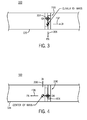
- the position of the cavities 216 and 218 in the proofmass 124 aligns the center of mass of the proofmass 124 at a position offset to the side of an output axis 404 for the proofmass 124.
- a pendulous axis 406 for the proofmass 124 is orthogonal to the output axis 404 and passes through the center of mass of the proofmass 124.
- the pendulous axis 406 is in-plane and the input axis 206 is out-of-plane to measure an out-of-plane acceleration.
- the input axes 202, 204, and 206 in one example intersect at a common point 502 and are substantially orthogonal.
- the orientation of the proofmass 124 may be chosen to place the input axis 206 at a location where the input axes 202 and 204 intersect.
- Orienting the input axes 202, 204, and 206 to intersect at the common point 502 serves to reduce a number of coefficients needed to compensate for the size effect in an inertial system.
- Compensation algorithms are employed to calculate the acceleration sensed by the proofmasses 120, 122, and 124.
- the compensation algorithms take into account the position of the input axes 202, 204, and 206. Since the input axes 202, 204, and 206 intersect at the common point 502, the compensation algorithms may be simplified.
- the proofmasses 120, 122, and 124 employ cross-leaf flexures 230 that couple the proofmasses 120, 122, and 124 with the frame 126.
- the cross-leaf flexures 230 comprise a first flexure component 602 and a second flexure component 604.
- the first flexure component 602 comprises a first flexure portion that is substantially parallel with the input axis 202.
- the second flexure component 604 comprises a second flexure portion that is substantially orthogonal to the input axis 202.
- the cross-leaf flexure 230 serves to prevent translation of the proofmasses 120, 122, and 124. Translation of the proofmasses 120, 122, and 124 causes scale factor non-linearity due to variation of the capacitor gap used for electrostatic forcing.
- the second flexure component 604 serves to reduce the compliancy of the first flexure component 602 and the first flexure component 602 serves to reduce the compliancy of the second flexure component 604.
- the proofmasses 120, 122, and 124 lay substantially in a plane.
- the second flexure component 604 serves to promote a reduction in compliancy of the proofmasses 120, 122, and 124 in a direction out of the plane.
- the second flexure component 604 provides stiffness to the cross-leaf flexures 230 for accelerations orthogonal to the plane of the first flexure component 602.
- the second flexure component 604 serves to reduce hinge sag.
- the first flexure component 602 comprises a cantilever beam flexure that is substantially coplanar with the proofmasses 120, 122, and 124.
- the second flexure component 604 comprises the second flexure portion that is substantially orthogonal to the cantilever beam flexure.
- the second flexure component 604 promotes an increase in the stiffness of the cross-leaf flexures 230 to out-of-plane motion.
- the MEMS triaxial planar accelerometer sensor chip 102 can be operated in either open or closed loop.
- the cross-leaf flexures 230 are designed to have a spring constant that limits the rotational motion of the proofmasses 120, 122, and 124 such that the proofmasses 120, 122, and 124 do not touch electrodes 130, 132, 134, 136, 138, and 140 at the maximum acceleration range.
- the MEMS triaxial planar accelerometer sensor chip 102 operates in a closed loop mode. In the closed loop mode, voltages are fed back to the electrodes 130, 132, 134, 136, 138, and 140 to develop electrostatic forces that maintain the pickoff at null.
- the electrostatic forcing method may be either voltage biased or charge control.
- the top cover 106 and bottom cover 108 serve to encapsulate the center element 104.
- the top cover 106 and the bottom cover 108 form a hermetically sealed sensor chip when bonded with the center element 104. Micro fabrication and bonding of the sensor chip is done at the wafer level.
- the bottom cover 108 is a silicon-on-insulator ("SOI") structure.
- An outer layer of the bottom cover 108 comprises a handle layer.
- An inner layer of the bottom cover 108 comprises a device layer.
- the device layer comprises a plurality of electrodes 130, 132, 134, 136, 138, and 140 and a guard ring 142.
- the device layer in one example comprises six isolated electrodes 130, 132, 134, 136, 138, and 140. Two of the electrodes 130, 132, 134, 136, 138, and 140 are associated with each of the proofmasses 120, 122, and 124.
- the dielectric layer 110 establishes a gap between the top cover 106 and the center element 104.
- the dielectric layer 112 establishes a gap between the center element 104 and the bottom cover 108.
- the dielectric layer 112 establishes the gap between the electrodes 130, 132, 134, 136, 138, and 140 and the proofmasses 120, 122, and 124.
- the electrodes 130, 132, 134, 136, 138, and 140 and the proofmasses 120, 122, and 124 form capacitive pickoff and forcer elements.
- Force rebalance servo electronics apply charge to the electrodes 130, 132, 134, 136, 138, and 140 to sense the displacement of the proofmasses 120, 122, and 124 and maintain the displacement at null.
- the electrodes 130, 132, 134, 136, 138, and 140 in combination with the servo electronics sense the acceleration induced rotational motion of the proofmasses 120, 122, and 124 as a differential capacitance and apply a pulse width modulated electrostatic force to maintain the proofmasses 120, 122, and 124 at null.
- the output of the planar accelerometer triad is converted to a pulse train with a scale factor of approximately 100 KHz per G in the range of ⁇ 50 G.
- the individual accelerometer channels within the triad can be scaled to different G ranges up to 1000 G for specific applications.
- the MEMS triaxial planar accelerometer sensor chip 102 in one example routes electrical signals from the proofmasses 120, 122, and 124 and the electrodes 130, 132, 134, 136, 138, and 140 to contact pads on a mounting surface of the MEMS triaxial planar accelerometer sensor chip 102.
- the MEMS triaxial planar accelerometer sensor chip 102 in one example employs the contact pads (e.g., solder pads) for ball grid array or flip chip mounting to a substrate 904.
- Electrical contacts 906 and 908 in one example transfer electrical signals from two of the electrodes 130, 132, 134, 136, 138, and 140 to the contact pads.
- Electrical contact 910 in one example transfers electrical signals from one of the proofmasses 120, 122, and 124 to the contact pads.
- the apparatus 100 in one example comprises a plurality of components such as hardware components. A number of such components can be combined or divided in one example of the apparatus 100.
- the apparatus 100 in one example comprises any (e.g., horizontal, oblique, or vertical) orientation, with the description and figures herein illustrating one exemplary orientation of the apparatus 100, for explanatory purposes.
Landscapes
- Physics & Mathematics (AREA)
- General Physics & Mathematics (AREA)
- Pressure Sensors (AREA)
- Micromachines (AREA)
- Gyroscopes (AREA)
- Electron Beam Exposure (AREA)
- Respiratory Apparatuses And Protective Means (AREA)
Applications Claiming Priority (3)
| Application Number | Priority Date | Filing Date | Title |
|---|---|---|---|
| US53494804P | 2004-01-07 | 2004-01-07 | |
| PCT/US2004/041853 WO2005069016A1 (en) | 2004-01-07 | 2004-12-13 | Coplanar proofmasses employable to sense acceleration along three axes |
| EP04814081A EP1711836A1 (de) | 2004-01-07 | 2004-12-13 | Zur messung von beschleunigung entlang dreier achsen verwendbare coplanare prüfmassen |
Related Parent Applications (2)
| Application Number | Title | Priority Date | Filing Date |
|---|---|---|---|
| EP04814081A Division EP1711836A1 (de) | 2004-01-07 | 2004-12-13 | Zur messung von beschleunigung entlang dreier achsen verwendbare coplanare prüfmassen |
| EP04814081.8 Division | 2004-12-13 |
Publications (3)
| Publication Number | Publication Date |
|---|---|
| EP2284545A2 true EP2284545A2 (de) | 2011-02-16 |
| EP2284545A3 EP2284545A3 (de) | 2014-09-03 |
| EP2284545B1 EP2284545B1 (de) | 2018-08-08 |
Family
ID=34794336
Family Applications (2)
| Application Number | Title | Priority Date | Filing Date |
|---|---|---|---|
| EP10181392.1A Expired - Lifetime EP2284545B1 (de) | 2004-01-07 | 2004-12-13 | Koplanare seismische Massen zur Bestimmung der Beschleunigung entlang drei Achsen |
| EP04814081A Withdrawn EP1711836A1 (de) | 2004-01-07 | 2004-12-13 | Zur messung von beschleunigung entlang dreier achsen verwendbare coplanare prüfmassen |
Family Applications After (1)
| Application Number | Title | Priority Date | Filing Date |
|---|---|---|---|
| EP04814081A Withdrawn EP1711836A1 (de) | 2004-01-07 | 2004-12-13 | Zur messung von beschleunigung entlang dreier achsen verwendbare coplanare prüfmassen |
Country Status (4)
| Country | Link |
|---|---|
| US (1) | US7178398B2 (de) |
| EP (2) | EP2284545B1 (de) |
| JP (1) | JP5137404B2 (de) |
| WO (1) | WO2005069016A1 (de) |
Families Citing this family (24)
| Publication number | Priority date | Publication date | Assignee | Title |
|---|---|---|---|---|
| US20070163346A1 (en) * | 2006-01-18 | 2007-07-19 | Honeywell International Inc. | Frequency shifting of rotational harmonics in mems devices |
| US7509748B2 (en) * | 2006-09-01 | 2009-03-31 | Seagate Technology Llc | Magnetic MEMS sensors |
| US7610809B2 (en) | 2007-01-18 | 2009-11-03 | Freescale Semiconductor, Inc. | Differential capacitive sensor and method of making same |
| US7957091B2 (en) | 2007-01-23 | 2011-06-07 | Seagate Technology Llc | Recordable disc with fluid bearing features |
| US7835110B2 (en) | 2007-01-23 | 2010-11-16 | Seagate Technology | MEMS disc drive |
| US7965589B2 (en) | 2007-01-23 | 2011-06-21 | Seagate Technology Llc | Recordable disc and motor |
| US7640786B2 (en) | 2007-03-28 | 2010-01-05 | Northrop Grumman Guidance And Electronics Company, Inc. | Self-calibrating accelerometer |
| US8006557B2 (en) * | 2007-05-16 | 2011-08-30 | Intellisense Software Corporation | Multi-axis sensor |
| US8468887B2 (en) * | 2008-04-14 | 2013-06-25 | Freescale Semiconductor, Inc. | Resonant accelerometer with low sensitivity to package stress |
| US8171793B2 (en) * | 2008-07-31 | 2012-05-08 | Honeywell International Inc. | Systems and methods for detecting out-of-plane linear acceleration with a closed loop linear drive accelerometer |
| US8779534B2 (en) | 2010-11-04 | 2014-07-15 | Meggitt (Orange County), Inc. | Low-G MEMS acceleration switch |
| US9229026B2 (en) * | 2011-04-13 | 2016-01-05 | Northrop Grumman Guaidance and Electronics Company, Inc. | Accelerometer systems and methods |
| DE102011057110A1 (de) * | 2011-12-28 | 2013-07-04 | Maxim Integrated Products, Inc. | MEMS-Beschleunigungssensor |
| US20150260752A1 (en) * | 2012-10-12 | 2015-09-17 | Panasonic Corporation | Acceleration sensor |
| US9612256B2 (en) * | 2013-02-20 | 2017-04-04 | Northrop Grumman Guidance And Electronics Company, Inc. | Range-dependent bias calibration of an accelerometer sensor system |
| US9612255B2 (en) * | 2013-02-20 | 2017-04-04 | Northrop Grumman Guidance And Electronic Company, Inc. | Range-dependent bias calibration of an accelerometer sensor system |
| DE102013222966A1 (de) * | 2013-11-12 | 2015-05-28 | Robert Bosch Gmbh | Inertialsensor |
| US9791470B2 (en) * | 2013-12-27 | 2017-10-17 | Intel Corporation | Magnet placement for integrated sensor packages |
| DE102014202816B4 (de) * | 2014-02-17 | 2022-06-30 | Robert Bosch Gmbh | Wippeneinrichtung für einen mikromechanischen Z-Sensor |
| US10330697B2 (en) | 2015-05-15 | 2019-06-25 | Honeywell International Inc. | Active, in-situ, calibration of MEMS accelerometers using optical forces |
| US9874581B2 (en) * | 2015-05-15 | 2018-01-23 | Honeywell International Inc. | In-situ bias correction for MEMS accelerometers |
| US9983225B2 (en) | 2015-06-29 | 2018-05-29 | Honeywell International Inc. | Optical-mechanical vibrating beam accelerometer |
| GB2579057A (en) * | 2018-11-16 | 2020-06-10 | Atlantic Inertial Systems Ltd | Accelerometer |
| WO2022241002A1 (en) | 2021-05-11 | 2022-11-17 | Stake Drive Systems, Llc | Object orientation indicator |
Family Cites Families (27)
| Publication number | Priority date | Publication date | Assignee | Title |
|---|---|---|---|---|
| US4574327A (en) * | 1984-05-18 | 1986-03-04 | Becton, Dickinson And Company | Capacitive transducer |
| GB2174500B (en) * | 1985-05-04 | 1988-02-10 | Stc Plc | Accelerometer |
| US4679434A (en) * | 1985-07-25 | 1987-07-14 | Litton Systems, Inc. | Integrated force balanced accelerometer |
| GB8628611D0 (en) * | 1986-11-29 | 1987-03-18 | Accelerometer | Temperature sensing arrangement |
| GB8718004D0 (en) * | 1987-07-29 | 1987-12-16 | Marconi Co Ltd | Accelerometer |
| DE3741036A1 (de) * | 1987-12-03 | 1989-06-15 | Fraunhofer Ges Forschung | Mikromechanischer beschleunigungsmesser |
| JPH01287470A (ja) * | 1987-12-26 | 1989-11-20 | Aisin Seiki Co Ltd | 半導体加速度センサ |
| US4825335A (en) * | 1988-03-14 | 1989-04-25 | Endevco Corporation | Differential capacitive transducer and method of making |
| US4919993A (en) * | 1989-02-27 | 1990-04-24 | Sundstrand Data Control, Inc. | Flexures and method for creating flexures in a wafer |
| US4928203A (en) * | 1989-02-28 | 1990-05-22 | United Technologies | Capacitive accelerometer with hinges on top and bottom surface |
| FR2650895B1 (fr) * | 1989-08-08 | 1991-10-11 | Onera (Off Nat Aerospatiale) | Capteur accelerometrique a poutres vibrant en flexion |
| DE4126100A1 (de) * | 1991-08-07 | 1993-02-18 | Univ Chemnitz Tech | Mikromechanischer drehbeschleunigungssensor |
| US5383363A (en) * | 1993-02-10 | 1995-01-24 | Ford Motor Company | Inertial measurement unit providing linear and angular outputs using only fixed linear accelerometer sensors |
| JPH08145782A (ja) * | 1994-11-23 | 1996-06-07 | Tokyo Gas Co Ltd | 予負荷線形ビーム振動センサおよびその製造方法 |
| US5488864A (en) * | 1994-12-19 | 1996-02-06 | Ford Motor Company | Torsion beam accelerometer with slotted tilt plate |
| JP2728237B2 (ja) * | 1995-03-27 | 1998-03-18 | 株式会社日立製作所 | 静電容量式加速度センサ |
| JPH09113534A (ja) * | 1995-10-23 | 1997-05-02 | Yoshinobu Matsumoto | 加速度センサー |
| JP3409565B2 (ja) * | 1996-03-01 | 2003-05-26 | 日産自動車株式会社 | 角速度センサの自己診断方法 |
| DE19649715C2 (de) * | 1996-11-30 | 2001-07-12 | Telefunken Microelectron | Anordnung zur Messung von Beschleunigungen |
| US6105427A (en) * | 1998-07-31 | 2000-08-22 | Litton Systems, Inc. | Micro-mechanical semiconductor accelerometer |
| EP1172657B1 (de) * | 2000-07-10 | 2006-08-23 | Infineon Technologies SensoNor AS | Beschleunigungssensor |
| DE10117630B4 (de) * | 2001-04-09 | 2005-12-29 | Eads Deutschland Gmbh | Mikromechanischer kapazitiver Beschleunigungssensor |
| JP3941694B2 (ja) * | 2001-11-19 | 2007-07-04 | 三菱電機株式会社 | 加速度センサ |
| JP2003329704A (ja) * | 2002-05-14 | 2003-11-19 | Mitsubishi Electric Corp | 慣性力センサ、およびその製造方法 |
| DE10225714A1 (de) * | 2002-06-11 | 2004-01-08 | Eads Deutschland Gmbh | Mehrachsiger monolithischer Beschleunigungssensor |
| US6829937B2 (en) * | 2002-06-17 | 2004-12-14 | Vti Holding Oy | Monolithic silicon acceleration sensor |
| GB0305857D0 (en) * | 2003-03-14 | 2003-04-16 | Europ Technology For Business | Accelerometers |
-
2004
- 2004-12-13 US US11/010,588 patent/US7178398B2/en not_active Expired - Lifetime
- 2004-12-13 EP EP10181392.1A patent/EP2284545B1/de not_active Expired - Lifetime
- 2004-12-13 EP EP04814081A patent/EP1711836A1/de not_active Withdrawn
- 2004-12-13 JP JP2006549283A patent/JP5137404B2/ja not_active Expired - Fee Related
- 2004-12-13 WO PCT/US2004/041853 patent/WO2005069016A1/en not_active Ceased
Non-Patent Citations (1)
| Title |
|---|
| None |
Also Published As
| Publication number | Publication date |
|---|---|
| EP2284545A3 (de) | 2014-09-03 |
| US20050145029A1 (en) | 2005-07-07 |
| JP5137404B2 (ja) | 2013-02-06 |
| EP1711836A1 (de) | 2006-10-18 |
| WO2005069016A1 (en) | 2005-07-28 |
| US7178398B2 (en) | 2007-02-20 |
| JP2007519902A (ja) | 2007-07-19 |
| EP2284545B1 (de) | 2018-08-08 |
Similar Documents
| Publication | Publication Date | Title |
|---|---|---|
| US7178398B2 (en) | Coplanar proofmasses employable to sense acceleration along three axes | |
| US11808574B2 (en) | Micromechanical detection structure of a MEMS multi-axis gyroscope, with reduced drifts of corresponding electrical parameters | |
| US12560432B2 (en) | Multi-mass MEMS motion sensor | |
| EP2462408B1 (de) | Mikromechanisch hergestellte trägheitssensorvorrichtungen | |
| US8096181B2 (en) | Inertial sensor | |
| US8739626B2 (en) | Micromachined inertial sensor devices | |
| US20180074090A1 (en) | Multiple degree of freedom mems sensor chip and method for fabricating the same | |
| EP3717400B1 (de) | Asymmetrischer beschleunigungsmesser ausserhalb der ebene | |
| EP1618391A2 (de) | Mikrobearbeiteter multisensor mit sechs freiheitsgraden | |
| US20070034007A1 (en) | Multi-axis micromachined accelerometer | |
| US20230266360A1 (en) | Accelerometer, inertial measurement unit imu, and electronic device | |
| JP6343102B2 (ja) | 慣性力センサ | |
| US7267005B1 (en) | SOI-MEMS gyroscope having three-fold symmetry | |
| US20060196266A1 (en) | Integrated gyroscope and temperature sensor | |
| US20230349945A1 (en) | Inertial sensor and inertial measurement unit | |
| JP2021032801A (ja) | 慣性センサーユニット、電子機器、及び移動体 | |
| JP7786163B2 (ja) | 物理量センサー、慣性計測装置及び製造方法 | |
| US20240053378A1 (en) | Physical Quantity Sensor And Inertial Measurement Unit | |
| US20240118308A1 (en) | Physical Quantity Sensor And Inertial Measurement Device |
Legal Events
| Date | Code | Title | Description |
|---|---|---|---|
| PUAI | Public reference made under article 153(3) epc to a published international application that has entered the european phase |
Free format text: ORIGINAL CODE: 0009012 |
|
| AC | Divisional application: reference to earlier application |
Ref document number: 1711836 Country of ref document: EP Kind code of ref document: P |
|
| AK | Designated contracting states |
Kind code of ref document: A2 Designated state(s): DE FR GB IT |
|
| RIN1 | Information on inventor provided before grant (corrected) |
Inventor name: STEWART, ROBERT Inventor name: HEEG, SUZANNE |
|
| RIC1 | Information provided on ipc code assigned before grant |
Ipc: G01P 15/08 20060101ALI20130529BHEP Ipc: G01P 15/18 20130101ALI20130529BHEP Ipc: G01P 15/125 20060101ALI20130529BHEP Ipc: G01P 15/00 20060101AFI20130529BHEP |
|
| RIC1 | Information provided on ipc code assigned before grant |
Ipc: G01P 15/125 20060101ALI20140326BHEP Ipc: G01P 15/08 20060101ALI20140326BHEP Ipc: G01P 15/18 20130101ALI20140326BHEP Ipc: G01P 15/00 20060101AFI20140326BHEP |
|
| PUAL | Search report despatched |
Free format text: ORIGINAL CODE: 0009013 |
|
| AK | Designated contracting states |
Kind code of ref document: A3 Designated state(s): DE FR GB IT |
|
| RIC1 | Information provided on ipc code assigned before grant |
Ipc: G01P 15/00 20060101AFI20140728BHEP Ipc: G01P 15/18 20130101ALI20140728BHEP Ipc: G01P 15/125 20060101ALI20140728BHEP Ipc: G01P 15/08 20060101ALI20140728BHEP |
|
| 17P | Request for examination filed |
Effective date: 20150220 |
|
| RBV | Designated contracting states (corrected) |
Designated state(s): DE FR GB IT |
|
| 17Q | First examination report despatched |
Effective date: 20170313 |
|
| GRAP | Despatch of communication of intention to grant a patent |
Free format text: ORIGINAL CODE: EPIDOSNIGR1 |
|
| INTG | Intention to grant announced |
Effective date: 20180518 |
|
| GRAS | Grant fee paid |
Free format text: ORIGINAL CODE: EPIDOSNIGR3 |
|
| GRAA | (expected) grant |
Free format text: ORIGINAL CODE: 0009210 |
|
| AC | Divisional application: reference to earlier application |
Ref document number: 1711836 Country of ref document: EP Kind code of ref document: P |
|
| AK | Designated contracting states |
Kind code of ref document: B1 Designated state(s): DE FR GB IT |
|
| REG | Reference to a national code |
Ref country code: GB Ref legal event code: FG4D |
|
| REG | Reference to a national code |
Ref country code: DE Ref legal event code: R081 Ref document number: 602004053036 Country of ref document: DE Owner name: NORTHROP GRUMMAN SYSTEMS CORP., FALLS CHURCH, US Free format text: FORMER OWNER: NORTHROP GRUMMAN CORP., WOODLANDS HILLS, CALIF., US |
|
| REG | Reference to a national code |
Ref country code: DE Ref legal event code: R096 Ref document number: 602004053036 Country of ref document: DE |
|
| REG | Reference to a national code |
Ref country code: DE Ref legal event code: R081 Ref document number: 602004053036 Country of ref document: DE Owner name: NORTHROP GRUMMAN SYSTEMS CORP., FALLS CHURCH, US Free format text: FORMER OWNER: NORTHROP GRUMMAN CORPORATION, WOODLANDS HILLS, CA, US Ref country code: DE Ref legal event code: R082 Ref document number: 602004053036 Country of ref document: DE Representative=s name: HERNANDEZ, YORCK, DIPL.-ING., DE |
|
| RAP2 | Party data changed (patent owner data changed or rights of a patent transferred) |
Owner name: NORTHROP GRUMMAN SYSTEMS CORPORATION |
|
| REG | Reference to a national code |
Ref country code: GB Ref legal event code: 732E Free format text: REGISTERED BETWEEN 20190314 AND 20190320 |
|
| REG | Reference to a national code |
Ref country code: DE Ref legal event code: R097 Ref document number: 602004053036 Country of ref document: DE |
|
| PLBE | No opposition filed within time limit |
Free format text: ORIGINAL CODE: 0009261 |
|
| STAA | Information on the status of an ep patent application or granted ep patent |
Free format text: STATUS: NO OPPOSITION FILED WITHIN TIME LIMIT |
|
| 26N | No opposition filed |
Effective date: 20190509 |
|
| P01 | Opt-out of the competence of the unified patent court (upc) registered |
Effective date: 20230607 |
|
| PGFP | Annual fee paid to national office [announced via postgrant information from national office to epo] |
Ref country code: GB Payment date: 20231220 Year of fee payment: 20 |
|
| PGFP | Annual fee paid to national office [announced via postgrant information from national office to epo] |
Ref country code: IT Payment date: 20231228 Year of fee payment: 20 Ref country code: FR Payment date: 20231221 Year of fee payment: 20 Ref country code: DE Payment date: 20231214 Year of fee payment: 20 |
|
| REG | Reference to a national code |
Ref country code: DE Ref legal event code: R071 Ref document number: 602004053036 Country of ref document: DE |
|
| REG | Reference to a national code |
Ref country code: GB Ref legal event code: PE20 Expiry date: 20241212 |
|
| PG25 | Lapsed in a contracting state [announced via postgrant information from national office to epo] |
Ref country code: GB Free format text: LAPSE BECAUSE OF EXPIRATION OF PROTECTION Effective date: 20241212 |
|
| PG25 | Lapsed in a contracting state [announced via postgrant information from national office to epo] |
Ref country code: GB Free format text: LAPSE BECAUSE OF EXPIRATION OF PROTECTION Effective date: 20241212 |