EP2284068A2 - Support de selle télescopique hydraulique - Google Patents
Support de selle télescopique hydraulique Download PDFInfo
- Publication number
- EP2284068A2 EP2284068A2 EP20090175132 EP09175132A EP2284068A2 EP 2284068 A2 EP2284068 A2 EP 2284068A2 EP 20090175132 EP20090175132 EP 20090175132 EP 09175132 A EP09175132 A EP 09175132A EP 2284068 A2 EP2284068 A2 EP 2284068A2
- Authority
- EP
- European Patent Office
- Prior art keywords
- tube
- seat post
- telescopic tube
- seatpost
- seat
- Prior art date
- Legal status (The legal status is an assumption and is not a legal conclusion. Google has not performed a legal analysis and makes no representation as to the accuracy of the status listed.)
- Withdrawn
Links
Images


Classifications
-
- B—PERFORMING OPERATIONS; TRANSPORTING
- B62—LAND VEHICLES FOR TRAVELLING OTHERWISE THAN ON RAILS
- B62J—CYCLE SADDLES OR SEATS; AUXILIARY DEVICES OR ACCESSORIES SPECIALLY ADAPTED TO CYCLES AND NOT OTHERWISE PROVIDED FOR, e.g. ARTICLE CARRIERS OR CYCLE PROTECTORS
- B62J1/00—Saddles or other seats for cycles; Arrangement thereof; Component parts
- B62J1/08—Frames for saddles; Connections between saddle frames and seat pillars; Seat pillars
-
- B—PERFORMING OPERATIONS; TRANSPORTING
- B62—LAND VEHICLES FOR TRAVELLING OTHERWISE THAN ON RAILS
- B62K—CYCLES; CYCLE FRAMES; CYCLE STEERING DEVICES; RIDER-OPERATED TERMINAL CONTROLS SPECIALLY ADAPTED FOR CYCLES; CYCLE AXLE SUSPENSIONS; CYCLE SIDE-CARS, FORECARS, OR THE LIKE
- B62K19/00—Cycle frames
- B62K19/30—Frame parts shaped to receive other cycle parts or accessories
- B62K19/36—Frame parts shaped to receive other cycle parts or accessories for attaching saddle pillars, e.g. adjustable during ride
Definitions
- the invention relates to a hydraulic telescopic seat post.
- telescopic seat post is referred to in the context of this document, a seat post whose height adjustment device is intended to be actuated while driving.
- Such seatposts meet in particular the needs of mountain bikers who prefer downhill often a lower saddle position than uphill.
- Such seat posts are already known.
- the shows US 7306206 B2 Such a hydraulic telescopic seat post.
- a disadvantage of such seat posts is that they are relatively expensive to produce. The invention has set itself the task of creating such a seat post without this disadvantage.
- the hydraulic telescopic seat post is intended in particular for a bicycle. It includes an inner telescopic tube and an outer telescopic tube. Furthermore, it comprises a support chamber and with the support chamber by a valve selectively connectable escape chamber. In addition, a valve actuating device is provided.
- the seatpost has a head with a saddle fastening device. The walls of at least one of the two mentioned Chambers include at least the outer telescopic tube. As a result, a condition for a particularly simple structure is created.
- the inner telescoping tube protrudes partially above the outer telescoping tube and at its upper end the saddle is secured.
- the support chamber is at least also filled with non-compressible or difficult to compress liquid, preferably oil.
- the support chamber is always filled, that is, in all operating states of the seat post, exclusively with oil.
- the walls of the support chamber also include at least the outer telescoping tube.
- the outer telescopic tube comprises a frame tube, particularly preferably the seat tube of a bicycle frame.
- the support chamber is thus formed in one embodiment, at least by the lower end of the seat tube.
- the seatpost is integrated in this way in the bicycle frame.
- the bicycle frame assumes essential functions of the height adjustment of the seat post. Compared with a telescopic seat post, in which the outer telescopic tube is formed by an extra component, thereby a significant weight saving and a simplified structure are possible.
- the escape chamber is provided in the inner telescopic tube and is, particularly preferably, formed by the latter.
- the escape chamber preferably comprises a closed space except for the connection to the support chamber, which can optionally be produced by means of the valve.
- a compressible medium preferably gas, and more preferably air, is preferably located in the escape chamber. This is compressed due to the seclusion of the escape chamber with incoming oil.
- the seat tube therefore differs from a conventional seat tube of a bicycle frame only in that a closure wall is provided in its lower region.
- the inner lower portion of the seat tube is, at least after completion of the bicycle frame, very difficult to reach.
- the valve is located in the head of the seatpost.
- the seat post head is particularly suitable for mounting a valve operating device, as it is easy to reach by the driver while driving.
- the support chamber has an upper portion that includes a channel in the inner telescoping tube.
- the size of the diameter of the channel is preferably less than half the size of the diameter of the inner telescopic tube
- the size of the diameter of the channel is most preferably less than one third of the size of the diameter of the inner telescopic tube.
- the valve is preferably arranged so that it communicates with the channel.
- the channel is preferably formed by a tube.
- the arrangement combines several advantages. It makes it possible to arrange the valve with the mentioned advantages in the head of the seat post, which makes it necessary to extend the support chamber up to the head of the seat post.
- the support chamber extends only with a greatly reduced diameter in the inner telescopic tube, the amount of at least hardly compressible liquid (preferably oil) in favor of a low total weight of the seat post is significantly reduced.
- the seat post according to the invention essentially comes without components in the lower region of the outer telescopic tube.
- the inventive seat post comes without a complex power transmission between the valve actuator and the valve in the inner telescopic tube.
- the channel extends through the entire length of the inner telescopic tube.
- the inner telescopic tube is preferably closed except for an opening on its underside, whose diameter is many times smaller than the diameter of the inner telescopic tube.
- a connecting piece is provided, which connects the channel to the opening of the inner telescopic tube.
- a connecting channel is provided, which leads from the valve in the seat post head to the lowest area of the escape chamber.
- This lowermost region of the escape chamber is preferably always filled with oil. This prevents that the gas present in the escape chamber can pass through the valve into the support chamber.
- the connecting channel is formed by a tube in the inner telescopic tube, which -particularly preferred- runs through almost the entire length of the inner telescopic tube.
- the inner telescopic tube By loading the inner telescopic tube (saddle), for example by the driver's weight with the valve open, the inner telescopic tube lowers in the outer telescopic tube. In this case, liquid flows from the support chamber through the valve into the connection channel and through this into the escape chamber. The gas present in the escape chamber is compressed. After closing the valve, the support chamber forms a closed space. Since it is filled with at least difficult to compress liquid, its volume is at least almost invariable. The inner telescopic tube is blocked in the outer telescopic tube against insertion and extension. By reopening the valve when the inner telescopic tube is not loaded (ie saddle), the fluid is forced back into the support chamber by the expanding compressed gas from the escape chamber through the connecting channel. Here, the inner telescopic tube and thus the saddle attached to this is automatically raised.
- the saddle fastening device comprises a clamping piece which is mounted on a sprag bearing in the head of the seat post.
- the fluid deflection which directs the fluid from the valve into the connection channel preferably passes through the clamping piece bearing.
- Means may be provided which avoid a rotation of the inner telescopic tube relative to the outer telescopic tube.
- These means may comprise a non-circular cross section of both telescopic tubes (for example drop shape) or projections on one of the two telescopic tubes which engage in complementary recesses of the other telescopic tube.
- linear ball bearings or the non-circular design of only one of the telescopic tubes are conceivable.
- valve actuator includes a lever attached to the seatpost head.
- valve actuating device comprises a lever which is provided on the handlebar of the bicycle and a Bowden cable or another means of force and / or signal transmission is operatively connected to the valve.
- a seal is provided between the inner and outer telescopic tube, which prevents leakage of the at least hardly compressible liquid. Since the seal is located in this easily accessible area, it can be well controlled, maintained and replaced if necessary.
- a connecting line for optional connectivity of the support chamber is provided with the escape chamber and this runs -besonders preferred- at least outside the seat post.
- the connecting line extends into an operating region of the bicycle, which can be easily reached by the user for actuating the seat post while driving.
- the valve is located on the connection line and preferably outside the seatpost.
- the valve is arranged in the actuation area.
- a particularly immediate Fernbetätigles the seat post is achieved. Because there are no means necessary, whose function is solely in the transmission of the operation, such as Bowden cables for remote operation of a valve disposed in or in the immediate vicinity of the seat post valve.
- Another advantage is that the valve, by being provided outside the seatpost, can also be conveniently reached for example for repair, maintenance or inspection purposes.
- the operating area is the handlebar area of a bicycle.
- the connecting line preferably extends to the handlebar of a bicycle and the valve is preferably arranged on the handlebar.
- the connecting line is at least partially flexible and, as is particularly preferred, comprises hydraulic hoses, then a more reliable one is Course of the connection line in an operating range with low manufacturing and assembly costs possible.
- connection line also runs inside the seatpost.
- It preferably comprises a guide tube there.
- the guide tube is preferably fastened in the seat post.
- the attachment is preferably provided such that the guide tube does not move relative to the bicycle frame during use of the seatpost.
- the guide tube is preferably fastened in the outer telescopic tube and particularly preferably at the lower end of the outer telescopic tube.
- the guide tube When the guide tube, as preferred, is adjustably fastened, it can, in addition to its function as part of the connecting line, take over another function, namely to effect an adjustable end stop.
- the guide tube is preferably clamped by means of a cone nut and thereby secured adjustable.
- the cone nut is preferably at least partially slotted.
- the guide tube extends from the outer telescopic tube into the inner telescopic tube.
- the diameter of the guide tube is preferably considerably smaller than the diameter of the inner telescopic tube and is particularly preferably about one third of the size of the diameter of the inner telescopic tube.
- the inner telescopic tube preferably has on its underside an opening, whose shape and size are matched to the shape and size of the guide tube, that this are guided through the opening and can slide well through the opening.
- the guide tube passed through the opening and this is sealed by a sealing device to allow the formation of an optional dense support chamber.
- the outer telescopic tube is a its lower portion preferably sealed by means of another sealing device to allow the formation of an optional dense support chamber.
- the connecting line extends from an opening in the side wall of the outer telescopic tube in the operating area, there has the valve and extends back to the outer telescopic tube, which at least partially traverses it as a guide tube before it enters the inner telescopic tube and ends there.
- an upper end stop of the seat post is provided, which limits the emergence of the inner telescopic tube from the outer telescopic tube, ie the maximum height of the seat post.
- a stop projection is preferably provided on the guide tube.
- the stop projection cooperates with a counter stop preferably provided in the inner telescopic tube.
- the guide tube is adjustably mounted, hereby also the stop projection and thus the upper end stop in a particularly simple and reliable manner adjustable.
- the stopper projection is preferably arranged at the upper end of the guide tube.
- the counter-stop is preferably arranged at the lower end of the inner telescopic tube.
- the seat tube does not meet with its lower end on the bottom bracket tube, as is the case at least in most known in the art bicycle frame shapes, but slightly before the bottom bracket on the down tube.
- the seat tube of the seat post according to the invention preferably terminates not above the pipe, which it meets with its lower end, but traverses this, so passes through it.
- the support chamber is accessible from below and it can be achieved in this way in this area arranged or to be arranged parts of the seat post, such as the guide tube, for assembly, maintenance or repair purposes.
- the invention also includes a bicycle frame, as well as a bicycle with a seat post according to the invention.
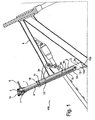
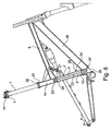
- the hydraulic telescopic seat post 100 comprises an inner telescopic tube 1 and an outer telescopic tube 2.
- the outer telescopic tube 2 is formed by a frame tube 9, namely the seat tube 10 of a bicycle frame 8. It is a support chamber 3 and provided via a valve 5 with this selectively connectable escape chamber 4a.
- the support chamber 3 is filled exclusively with oil 3b, 3c, 26. Since the oil 3b, 3c, 26 can not escape when the valve 5 is closed and is difficult to compress, the support chamber 3, with the valve 5 closed, ensures that the inner telescopic tube 1 is blocked in the longitudinal direction with respect to the seat tube 10.
- the support chamber 3 extends in the in the Fig. 1 to 6 In the lower portion 10a of the seat tube, the walls of the support chamber 3 are formed by the seat tube 10, the support chamber 3 has in this area therefore the diameter of the seat tube 10th In the inner telescopic tube 1, the support chamber 3 extends in its upper portion 3a only in the form of a channel 11, whose diameter is considerably smaller than the diameter of the inner telescopic tube 1. In the embodiment shown, the diameter of the channel 11 is only about one third as large as the diameter of the inner telescopic tube 1. The channel 11 extends through the entire length of the inner telescopic tube 1. The channel 11 thus connects the lower portion of the seat tube 10a with the Head 7 of the seat post.
- the inner telescopic tube 1 has an opening 1a on its underside on, with the channel 11 is connected via a connecting piece 12.
- the valve 5 is arranged in the seatpost head 7 on the channel 11. Therefore, it can be operated via the valve operating device 6, which is also arranged on the seatpost head 7, via short transmission paths.
- the escape chamber 4 a is formed by the inner telescopic tube 1. It is provided below a connecting channel 13 which extends almost through the entire length of the inner telescopic tube 1.
- the connecting channel 13 in the illustrated embodiment has a similar diameter as the channel 11 of the support chamber 3 and is like this always filled exclusively with oil 4.
- a saddle fastening device 14 is provided at the upper end of the inner telescopic tube 1, ie at the head 7 of the seat post.
- This comprises a clamping piece 15 which is mounted on a clamping piece bearing 16.
- the Klemm consultancylager 16 simultaneously forms the fluid deflection 17, which connects the upper region of the support chamber 3 a, so the channel 11 with the connecting channel 13.
- the connecting channel 13 thus connects the valve 5 (by means of the liquid deflection 17) with the lowermost region of the escape chamber 4a.
- 3d oil is always present in the escape chamber 4a.
- the lower open end of the connecting channel 13 is always located below the oil level 4b.
- connection channel 13 In this way, it is precluded that air 19 enters the connection channel 13 and in this way into the support chamber 3.
- the oil 3b, 3c of the support chamber 3 deviates into the escape chamber 4a, where it compresses the air 19 present there.
- the channel 11 and the connecting channel 13 are formed by tubes.
- the seal 18 in the upper region of the seat tube 10 between the inner telescopic tube 1 and the seat tube 10 prevents leakage of the oil.
- the lower portion of the seat tube 10a differs from a conventional seat tube only by a closing wall 10b which seals the lower portion of the seat tube 10a.
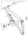
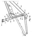
- Fig. 7 outlined the principle of another embodiment of the seat post 100 according to the invention.
- the escape chamber 4 a is formed by the inner telescopic tube 1.
- the optional connection of support chamber 3 and escape chamber 4a takes place here through a connecting line 20. This runs partially outside of the seat post 100th
- connection line 20 starts at an exit 28 formed by an opening in the seat tube 10. It runs from there, formed by hydraulic lines which comprise hydraulic hoses 20a, into the handlebar area 21 of the bicycle.
- the valve 5 and a valve actuating device, not shown, is provided by means of which the continuity of the connecting line 20 can be selectively made or canceled.
- the connecting line 20 extends back to the seat post 100. It passes through the saddle tube opening 35 and enters in the form of the guide tube 22 in the supporting chamber 3 formed by the seat tube.
- the guide tube 22 has about one third of the diameter of the seat tube 10. It has substantially the same longitudinal axis as the seat tube 10. The guide tube 22, without establishing a connection to the support chamber 3, through the opening 27 in the inner telescopic tube 1 and thus the escape chamber 4 a and ends there.
- the support chamber 3 and the connecting line 20 are, like the hatching in Fig. 7 should show, always completely filled with oil 26 or another not or hardly compressible, preferably liquid medium.
- the escape chamber 4a is, like the in Fig. 7 and 10 shown oil level 4b, partially filled with oil 26.
- a compressible, preferably gaseous medium, for example air 29, is provided in the escape chamber 4a.
- the arrow p in Fig. 7 illustrates the movement of the inner telescopic tube 1 during the adjustment of the seat post 100th
- the inner telescopic tube 1 has in both embodiments shown a slightly smaller diameter than the outer telescopic tube 2, inter alia to allow one another sliding of the two tubes.
- a sealing device 32 is provided at the upper end of the outer telescopic tube 2 of both embodiments shown in the in FIGS. 7 to 10 embodiment shown comprises two O-rings.
- the inner telescopic tube 1 is closed at its bottom with the exception of the opening 27.
- the opening 27 is largely filled by the guided through the opening 27 guide tube 22 through which the aperture 27 slides during the adjustment process.
- the opening 27 is sealed for example by means of a piston rod seal.
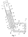
- Fig. 8 illustrates the effect of the upper end stop.
- the extract of the inner telescopic tube 1 from the outer telescopic tube 2 is limited by the provided at the end of the guide tube 22 stop projection 23 which comes at fully extended seat post on the counter-stop 24 to the plant at the lower end of the inner telescopic tube 1 around the aperture 27 around is arranged.
- the guide tube 22 is clamped by means of an insert 30 and a cone nut 31 in the outer telescopic tube 2. After loosening the cone nut 31, the guide tube 22 can be moved up or down and by the hereby take place displacement of the stop projection 23, the maximum height of the saddle, which occurs at relieved saddle and open valve 5, be increased or decreased.
- the support chamber 3 is sealed at its lower end. In conjunction with the other sealing devices, this results in a only by the connecting line 20 or the valve 5 optionally aufhebbare seal the support chamber. 3
- Fig. 10 illustrates the insertion of the inner telescopic tube 1 is limited in the outer telescopic tube 2 by striking the lower side of the inner telescopic tube 1 on the insert 30.
- a cylindrical extension is arranged, which, as well as the lower end of the guide tube 22, an external thread 34, 34 ', for establishing the connection with the hydraulic hoses 20a. It is conceivable to guide the hydraulic hoses 20a at least partially within the frame tubes.
- valve 5 When the valve 5 is closed no oil can escape from the support chamber 3 and the seat post 100 is blocked at the selected height. To adjust the seat post, the valve 5 must be opened. If the seatpost is not yet at its lower stop and is loaded (for example, by the body weight of the user), then oil 26 flows from the support chamber 3 through the connecting line 20 into the escape chamber 4a. At the same time, the inner telescopic tube 1 slides into the outer telescopic tube 2, whereby the total length of the seat post 100 and thus the saddle height is reduced. The inner telescopic tube 1 forming the escape chamber 4a forms, with the exception of the aperture 27, a closed space. By the flow of the oil 26 into the escape chamber 4a, the air 29, which is located in this, therefore compressed.
- the compressed air 29 acts as a spring by the oil 26 through the connecting line 20 back into the support chamber 3 suppressed (if the seat post is not already arrived at its upper end stop).
- the inner telescopic tube 1 is raised and with this the saddle.
- the seat post can be blocked at any height, ie continuously, by closing the valve 5.
- a sliding bush 33 may be provided of a material which, in mating with the material of the inner telescopic tube 1, causes a low coefficient of friction, for example special plastic.
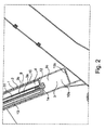
- the seat tube 10 meets the down tube 25 at a short distance from the bottom bracket tube and traverses it.
- the interior of the seat tube 10 is therefore freely accessible through its lower opening 35 from below.
- elements of the seatpost 100, such as the guide tube 22 can be conveniently mounted, maintained and repaired.
Landscapes
- Engineering & Computer Science (AREA)
- Mechanical Engineering (AREA)
- Fluid-Damping Devices (AREA)
Applications Claiming Priority (1)
| Application Number | Priority Date | Filing Date | Title |
|---|---|---|---|
| DE202009005132U DE202009005132U1 (de) | 2009-08-13 | 2009-08-13 | Hydraulische Teleskop-Sattelstütze |
Publications (1)
| Publication Number | Publication Date |
|---|---|
| EP2284068A2 true EP2284068A2 (fr) | 2011-02-16 |
Family
ID=43216398
Family Applications (1)
| Application Number | Title | Priority Date | Filing Date |
|---|---|---|---|
| EP20090175132 Withdrawn EP2284068A2 (fr) | 2009-08-13 | 2009-11-05 | Support de selle télescopique hydraulique |
Country Status (2)
| Country | Link |
|---|---|
| EP (1) | EP2284068A2 (fr) |
| DE (1) | DE202009005132U1 (fr) |
Cited By (4)
| Publication number | Priority date | Publication date | Assignee | Title |
|---|---|---|---|---|
| US10202158B2 (en) | 2016-08-31 | 2019-02-12 | Giant Manufacturing Co., Ltd. | Adjustable seat tube structure and bicycle |
| US10752307B2 (en) | 2015-07-21 | 2020-08-25 | Lupaan Gmbh | Positioning device having a telescoping element and a supporting element for seat posts |
| US10752308B2 (en) | 2015-07-21 | 2020-08-25 | Lupaan Gmbh | Telescopic seat post for bicycle frames |
| US10864955B2 (en) | 2016-06-06 | 2020-12-15 | Lupaan Gmbh | Telescopic seat post |
Citations (1)
| Publication number | Priority date | Publication date | Assignee | Title |
|---|---|---|---|---|
| US7306206B2 (en) | 2004-09-29 | 2007-12-11 | Maverick American Llc | Adjustable bicycle seat assemblies and methods of use |
Family Cites Families (4)
| Publication number | Priority date | Publication date | Assignee | Title |
|---|---|---|---|---|
| DE651151C (de) * | 1937-10-08 | Friedrich Teichert | Verstellbare Sattelstuetze mit OElabfederung | |
| DE19541760C2 (de) * | 1995-11-09 | 2000-06-21 | Guenter Schroeder | Vorrichtung zur Höhenverstellung eines Fahrradsattels |
| DE20005224U1 (de) * | 2000-03-20 | 2001-07-05 | Albrecht Stephan | Fahrrad |
| DE202007014515U1 (de) * | 2007-10-17 | 2008-01-10 | Kind Shock Hi-Tech Co. Ltd. | Verstellbare Sattelstütze |
-
2009
- 2009-08-13 DE DE202009005132U patent/DE202009005132U1/de not_active Expired - Lifetime
- 2009-11-05 EP EP20090175132 patent/EP2284068A2/fr not_active Withdrawn
Patent Citations (1)
| Publication number | Priority date | Publication date | Assignee | Title |
|---|---|---|---|---|
| US7306206B2 (en) | 2004-09-29 | 2007-12-11 | Maverick American Llc | Adjustable bicycle seat assemblies and methods of use |
Cited By (5)
| Publication number | Priority date | Publication date | Assignee | Title |
|---|---|---|---|---|
| US10752307B2 (en) | 2015-07-21 | 2020-08-25 | Lupaan Gmbh | Positioning device having a telescoping element and a supporting element for seat posts |
| US10752308B2 (en) | 2015-07-21 | 2020-08-25 | Lupaan Gmbh | Telescopic seat post for bicycle frames |
| US10864955B2 (en) | 2016-06-06 | 2020-12-15 | Lupaan Gmbh | Telescopic seat post |
| US10202158B2 (en) | 2016-08-31 | 2019-02-12 | Giant Manufacturing Co., Ltd. | Adjustable seat tube structure and bicycle |
| AU2017221795B2 (en) * | 2016-08-31 | 2019-04-18 | Giant Manufacturing Co., Ltd | Adjustable seat tube structure and bicycle |
Also Published As
| Publication number | Publication date |
|---|---|
| DE202009005132U1 (de) | 2010-12-30 |
Similar Documents
| Publication | Publication Date | Title |
|---|---|---|
| DE102007030006B4 (de) | Vakuumventil | |
| EP1319787B1 (fr) | Amortisseur pour éléments de meubles mobiles | |
| DE19506220A1 (de) | Türschließer | |
| DE112014003997T5 (de) | Fluidsteuerventil | |
| DE112008001260B4 (de) | Durchflussregelventilanordnung mit geringer Geräuschentwicklung | |
| DE102008010249A1 (de) | Antriebseinrichtung | |
| EP2284068A2 (fr) | Support de selle télescopique hydraulique | |
| DE19744040A1 (de) | Ventileinrichtung | |
| DE2744917C3 (de) | Sitzventil mit geradem Durchgang | |
| EP1468220B1 (fr) | Garniture | |
| DE10145200B4 (de) | Türschließer | |
| DE102014114486B4 (de) | Ablaufstutzen | |
| DE102013106273A1 (de) | Vorrichtung zum Halten einer Stütze an einem Trägergestell | |
| EP2959180B1 (fr) | Unité cylindre-piston | |
| EP3948013B1 (fr) | Arrangement support de selle réglable | |
| DE10027598B4 (de) | Ventil | |
| DE2458321B2 (de) | Stellventil | |
| DE102015106134A1 (de) | Schwenkanordnung | |
| DE102016101664B4 (de) | Axialventil | |
| DE102005060869B4 (de) | Betätigungsanordnung | |
| DE102013007912B4 (de) | Gurtstraffer-Kabelführungsteil sowie Gurtstraffer | |
| DE102005038765B4 (de) | Zugfederanordnung | |
| DE102006049582B4 (de) | Teleskopdämpfer | |
| WO1999053216A1 (fr) | Amortisseur utilisant un fluide comme agent d'amortissement et reglable en longueur | |
| WO2021013295A1 (fr) | Cylindre de tige de piston pneumatique ou hydraulique |
Legal Events
| Date | Code | Title | Description |
|---|---|---|---|
| PUAI | Public reference made under article 153(3) epc to a published international application that has entered the european phase |
Free format text: ORIGINAL CODE: 0009012 |
|
| AK | Designated contracting states |
Kind code of ref document: A2 Designated state(s): AT BE BG CH CY CZ DE DK EE ES FI FR GB GR HR HU IE IS IT LI LT LU LV MC MK MT NL NO PL PT RO SE SI SK SM TR |
|
| AX | Request for extension of the european patent |
Extension state: AL BA RS |
|
| STAA | Information on the status of an ep patent application or granted ep patent |
Free format text: STATUS: THE APPLICATION IS DEEMED TO BE WITHDRAWN |
|
| 18D | Application deemed to be withdrawn |
Effective date: 20120601 |